JP2010025108A - Heat pipe for removing thermal energy from exhaust gas - Google Patents
Heat pipe for removing thermal energy from exhaust gas Download PDFInfo
- Publication number
- JP2010025108A JP2010025108A JP2009166228A JP2009166228A JP2010025108A JP 2010025108 A JP2010025108 A JP 2010025108A JP 2009166228 A JP2009166228 A JP 2009166228A JP 2009166228 A JP2009166228 A JP 2009166228A JP 2010025108 A JP2010025108 A JP 2010025108A
- Authority
- JP
- Japan
- Prior art keywords
- exhaust
- heat pipes
- turbomachine
- heat pipe
- thermal energy
- Prior art date
- Legal status (The legal status is an assumption and is not a legal conclusion. Google has not performed a legal analysis and makes no representation as to the accuracy of the status listed.)
- Granted
Links
Images


Classifications
-
- F—MECHANICAL ENGINEERING; LIGHTING; HEATING; WEAPONS; BLASTING
- F02—COMBUSTION ENGINES; HOT-GAS OR COMBUSTION-PRODUCT ENGINE PLANTS
- F02C—GAS-TURBINE PLANTS; AIR INTAKES FOR JET-PROPULSION PLANTS; CONTROLLING FUEL SUPPLY IN AIR-BREATHING JET-PROPULSION PLANTS
- F02C7/00—Features, components parts, details or accessories, not provided for in, or of interest apart form groups F02C1/00 - F02C6/00; Air intakes for jet-propulsion plants
- F02C7/12—Cooling of plants
-
- F—MECHANICAL ENGINEERING; LIGHTING; HEATING; WEAPONS; BLASTING
- F01—MACHINES OR ENGINES IN GENERAL; ENGINE PLANTS IN GENERAL; STEAM ENGINES
- F01D—NON-POSITIVE DISPLACEMENT MACHINES OR ENGINES, e.g. STEAM TURBINES
- F01D25/00—Component parts, details, or accessories, not provided for in, or of interest apart from, other groups
- F01D25/08—Cooling; Heating; Heat-insulation
- F01D25/12—Cooling
-
- F—MECHANICAL ENGINEERING; LIGHTING; HEATING; WEAPONS; BLASTING
- F01—MACHINES OR ENGINES IN GENERAL; ENGINE PLANTS IN GENERAL; STEAM ENGINES
- F01D—NON-POSITIVE DISPLACEMENT MACHINES OR ENGINES, e.g. STEAM TURBINES
- F01D25/00—Component parts, details, or accessories, not provided for in, or of interest apart from, other groups
- F01D25/30—Exhaust heads, chambers, or the like
-
- F—MECHANICAL ENGINEERING; LIGHTING; HEATING; WEAPONS; BLASTING
- F01—MACHINES OR ENGINES IN GENERAL; ENGINE PLANTS IN GENERAL; STEAM ENGINES
- F01N—GAS-FLOW SILENCERS OR EXHAUST APPARATUS FOR MACHINES OR ENGINES IN GENERAL; GAS-FLOW SILENCERS OR EXHAUST APPARATUS FOR INTERNAL COMBUSTION ENGINES
- F01N3/00—Exhaust or silencing apparatus having means for purifying, rendering innocuous, or otherwise treating exhaust
- F01N3/02—Exhaust or silencing apparatus having means for purifying, rendering innocuous, or otherwise treating exhaust for cooling, or for removing solid constituents of, exhaust
- F01N3/04—Exhaust or silencing apparatus having means for purifying, rendering innocuous, or otherwise treating exhaust for cooling, or for removing solid constituents of, exhaust using liquids
- F01N3/043—Exhaust or silencing apparatus having means for purifying, rendering innocuous, or otherwise treating exhaust for cooling, or for removing solid constituents of, exhaust using liquids without contact between liquid and exhaust gases
-
- F—MECHANICAL ENGINEERING; LIGHTING; HEATING; WEAPONS; BLASTING
- F01—MACHINES OR ENGINES IN GENERAL; ENGINE PLANTS IN GENERAL; STEAM ENGINES
- F01N—GAS-FLOW SILENCERS OR EXHAUST APPARATUS FOR MACHINES OR ENGINES IN GENERAL; GAS-FLOW SILENCERS OR EXHAUST APPARATUS FOR INTERNAL COMBUSTION ENGINES
- F01N3/00—Exhaust or silencing apparatus having means for purifying, rendering innocuous, or otherwise treating exhaust
- F01N3/08—Exhaust or silencing apparatus having means for purifying, rendering innocuous, or otherwise treating exhaust for rendering innocuous
- F01N3/10—Exhaust or silencing apparatus having means for purifying, rendering innocuous, or otherwise treating exhaust for rendering innocuous by thermal or catalytic conversion of noxious components of exhaust
- F01N3/18—Exhaust or silencing apparatus having means for purifying, rendering innocuous, or otherwise treating exhaust for rendering innocuous by thermal or catalytic conversion of noxious components of exhaust characterised by methods of operation; Control
- F01N3/20—Exhaust or silencing apparatus having means for purifying, rendering innocuous, or otherwise treating exhaust for rendering innocuous by thermal or catalytic conversion of noxious components of exhaust characterised by methods of operation; Control specially adapted for catalytic conversion ; Methods of operation or control of catalytic converters
- F01N3/2006—Periodically heating or cooling catalytic reactors, e.g. at cold starting or overheating
- F01N3/2046—Periodically cooling catalytic reactors
-
- F—MECHANICAL ENGINEERING; LIGHTING; HEATING; WEAPONS; BLASTING
- F01—MACHINES OR ENGINES IN GENERAL; ENGINE PLANTS IN GENERAL; STEAM ENGINES
- F01N—GAS-FLOW SILENCERS OR EXHAUST APPARATUS FOR MACHINES OR ENGINES IN GENERAL; GAS-FLOW SILENCERS OR EXHAUST APPARATUS FOR INTERNAL COMBUSTION ENGINES
- F01N2240/00—Combination or association of two or more different exhaust treating devices, or of at least one such device with an auxiliary device, not covered by indexing codes F01N2230/00 or F01N2250/00, one of the devices being
- F01N2240/02—Combination or association of two or more different exhaust treating devices, or of at least one such device with an auxiliary device, not covered by indexing codes F01N2230/00 or F01N2250/00, one of the devices being a heat exchanger
-
- F—MECHANICAL ENGINEERING; LIGHTING; HEATING; WEAPONS; BLASTING
- F01—MACHINES OR ENGINES IN GENERAL; ENGINE PLANTS IN GENERAL; STEAM ENGINES
- F01N—GAS-FLOW SILENCERS OR EXHAUST APPARATUS FOR MACHINES OR ENGINES IN GENERAL; GAS-FLOW SILENCERS OR EXHAUST APPARATUS FOR INTERNAL COMBUSTION ENGINES
- F01N3/00—Exhaust or silencing apparatus having means for purifying, rendering innocuous, or otherwise treating exhaust
- F01N3/08—Exhaust or silencing apparatus having means for purifying, rendering innocuous, or otherwise treating exhaust for rendering innocuous
- F01N3/10—Exhaust or silencing apparatus having means for purifying, rendering innocuous, or otherwise treating exhaust for rendering innocuous by thermal or catalytic conversion of noxious components of exhaust
- F01N3/18—Exhaust or silencing apparatus having means for purifying, rendering innocuous, or otherwise treating exhaust for rendering innocuous by thermal or catalytic conversion of noxious components of exhaust characterised by methods of operation; Control
- F01N3/20—Exhaust or silencing apparatus having means for purifying, rendering innocuous, or otherwise treating exhaust for rendering innocuous by thermal or catalytic conversion of noxious components of exhaust characterised by methods of operation; Control specially adapted for catalytic conversion ; Methods of operation or control of catalytic converters
- F01N3/2066—Selective catalytic reduction [SCR]
-
- F—MECHANICAL ENGINEERING; LIGHTING; HEATING; WEAPONS; BLASTING
- F01—MACHINES OR ENGINES IN GENERAL; ENGINE PLANTS IN GENERAL; STEAM ENGINES
- F01N—GAS-FLOW SILENCERS OR EXHAUST APPARATUS FOR MACHINES OR ENGINES IN GENERAL; GAS-FLOW SILENCERS OR EXHAUST APPARATUS FOR INTERNAL COMBUSTION ENGINES
- F01N3/00—Exhaust or silencing apparatus having means for purifying, rendering innocuous, or otherwise treating exhaust
- F01N3/08—Exhaust or silencing apparatus having means for purifying, rendering innocuous, or otherwise treating exhaust for rendering innocuous
- F01N3/10—Exhaust or silencing apparatus having means for purifying, rendering innocuous, or otherwise treating exhaust for rendering innocuous by thermal or catalytic conversion of noxious components of exhaust
- F01N3/24—Exhaust or silencing apparatus having means for purifying, rendering innocuous, or otherwise treating exhaust for rendering innocuous by thermal or catalytic conversion of noxious components of exhaust characterised by constructional aspects of converting apparatus
- F01N3/28—Construction of catalytic reactors
- F01N3/2882—Catalytic reactors combined or associated with other devices, e.g. exhaust silencers or other exhaust purification devices
- F01N3/2889—Catalytic reactors combined or associated with other devices, e.g. exhaust silencers or other exhaust purification devices with heat exchangers in a single housing
-
- F—MECHANICAL ENGINEERING; LIGHTING; HEATING; WEAPONS; BLASTING
- F05—INDEXING SCHEMES RELATING TO ENGINES OR PUMPS IN VARIOUS SUBCLASSES OF CLASSES F01-F04
- F05D—INDEXING SCHEME FOR ASPECTS RELATING TO NON-POSITIVE-DISPLACEMENT MACHINES OR ENGINES, GAS-TURBINES OR JET-PROPULSION PLANTS
- F05D2260/00—Function
- F05D2260/20—Heat transfer, e.g. cooling
- F05D2260/208—Heat transfer, e.g. cooling using heat pipes
-
- F—MECHANICAL ENGINEERING; LIGHTING; HEATING; WEAPONS; BLASTING
- F05—INDEXING SCHEMES RELATING TO ENGINES OR PUMPS IN VARIOUS SUBCLASSES OF CLASSES F01-F04
- F05D—INDEXING SCHEME FOR ASPECTS RELATING TO NON-POSITIVE-DISPLACEMENT MACHINES OR ENGINES, GAS-TURBINES OR JET-PROPULSION PLANTS
- F05D2270/00—Control
- F05D2270/01—Purpose of the control system
- F05D2270/08—Purpose of the control system to produce clean exhaust gases
- F05D2270/082—Purpose of the control system to produce clean exhaust gases with as little NOx as possible
-
- Y—GENERAL TAGGING OF NEW TECHNOLOGICAL DEVELOPMENTS; GENERAL TAGGING OF CROSS-SECTIONAL TECHNOLOGIES SPANNING OVER SEVERAL SECTIONS OF THE IPC; TECHNICAL SUBJECTS COVERED BY FORMER USPC CROSS-REFERENCE ART COLLECTIONS [XRACs] AND DIGESTS
- Y02—TECHNOLOGIES OR APPLICATIONS FOR MITIGATION OR ADAPTATION AGAINST CLIMATE CHANGE
- Y02T—CLIMATE CHANGE MITIGATION TECHNOLOGIES RELATED TO TRANSPORTATION
- Y02T10/00—Road transport of goods or passengers
- Y02T10/10—Internal combustion engine [ICE] based vehicles
- Y02T10/12—Improving ICE efficiencies
Abstract
Description
本願発明は、ターボ機械に関する。より具体的には、本願発明は、ターボ機械の排気ガスの冷却に関する。 The present invention relates to a turbomachine. More specifically, the present invention relates to cooling of exhaust gas from turbomachines.
例えばガスタービン発電プラントなどのターボ機械からの排気ガスは、大気中に放出する排気ガスの組成に対する厳しい規制要件を満たさなければならないことが多い。排気ガス中に一般的に見られかつ規制の対象となる成分の1つは、NOxである。排気ストリームからNOxを除去するために、選択触媒還元(SCR)法のような方法が用いられることが多い。SCR法では、アンモニア(NH3)などをNOxと反応させ、窒素(N2)と水(H2O)とを生成させる。SCR法の有効性は、処理する排気ガスの温度に応じて決まる。ターボ機械からの排気ガスは、多くの場合に約1100°Fであり、SCRに先立って冷却して、要件を満たすようにSCRの有効性を高めなければならない。この冷却は一般的に、大型ファンシステムによって排気ガスストリーム中に強制的に流す低温外気で排気ガスを希釈することによって達成される。このファンシステムは、高流量かつ高圧力が可能でなければならず、従ってターボ機械を作動させる上での複雑さ及び費用を増加させる。 Exhaust gases from turbomachines such as gas turbine power plants often have to meet stringent regulatory requirements for the composition of the exhaust gases released into the atmosphere. One subject to component commonly seen and regulation in the exhaust gas is NO x. Methods such as the selective catalytic reduction (SCR) method are often used to remove NO x from the exhaust stream. In the SCR method, ammonia (NH 3 ) or the like is reacted with NO x to generate nitrogen (N 2 ) and water (H 2 O). The effectiveness of the SCR method depends on the temperature of the exhaust gas to be processed. Exhaust gas from turbomachines is often about 1100 ° F. and must be cooled prior to the SCR to increase the effectiveness of the SCR to meet requirements. This cooling is generally accomplished by diluting the exhaust gas with cold ambient air that is forced into the exhaust gas stream by a large fan system. This fan system must be capable of high flow rates and pressures, thus increasing the complexity and cost of operating the turbomachine.
本発明の1つの態様によると、ターボ機械は、それに沿って排気を導きかつ放出する少なくとも1つの排気通路と、排気から規制物質を除去することができる少なくとも1つの排気処理装置とを含む。複数のヒートパイプが、少なくとも1つの排気処理装置の上流で少なくとも部分的に排気通路内に配置される。複数のヒートパイプは、排気から該複数のヒートパイプに熱エネルギーを伝達させ、従って該排気の温度を低下させて少なくとも1つの排気処理装置の有効性を高めることができる。 According to one aspect of the present invention, a turbomachine includes at least one exhaust passage for directing and releasing exhaust along it, and at least one exhaust treatment device capable of removing regulated substances from the exhaust. A plurality of heat pipes are disposed at least partially in the exhaust passage upstream of the at least one exhaust treatment device. The plurality of heat pipes can transfer thermal energy from the exhaust to the plurality of heat pipes, thus reducing the temperature of the exhaust and increasing the effectiveness of the at least one exhaust treatment device.
本発明の別の態様によると、ターボ機械排気を放出する方法は、少なくとも1つの排気通路に沿ってターボ機械排気を強制的に流すステップと、複数のヒートパイプを通過させて排気を流すステップとを含む。熱エネルギーが、排気から複数のヒートパイプに伝達され、従って該排気の温度を低下させる。排気は、少なくとも1つの排気処理装置を通して流されて、該排気から規制物質を除去した後に排気を放免する。 According to another aspect of the present invention, a method of releasing turbomachine exhaust includes forcing turbomachine exhaust along at least one exhaust passage, and passing exhaust through a plurality of heat pipes. including. Thermal energy is transferred from the exhaust to the plurality of heat pipes, thus reducing the temperature of the exhaust. The exhaust is flowed through at least one exhaust treatment device to release the exhaust after removing regulated substances from the exhaust.
これら及びその他の利点並びに特徴は、図面と関連させてなした以下の説明から一層明らかになるであろう。 These and other advantages and features will become more apparent from the following description taken in conjunction with the drawings.
本願発明は、特許請求の範囲に具体的に記載されかつ明確に特許請求している。本発明の前述の及びその他の目的、特徴並びに利点は、添付図面と関連させてなした以下の詳細な説明から明らかである。 The invention of the present application is specifically described in the claims and explicitly claimed. The foregoing and other objects, features and advantages of the present invention will be apparent from the following detailed description taken in conjunction with the accompanying drawings.
以下の詳細な説明は、図面を参照して実施例によって、その利点及び特徴と共に本発明の実施形態を説明する。 The following detailed description explains embodiments of the invention, together with advantages and features, by way of example with reference to the drawings.
図1には、例えばガスタービン10などのターボ機械の実施形態の概略図を示す。ガスタービン10は、1以上の燃焼器12を含み、燃焼器内で燃料及び圧縮空気が混合されかつ点火される。高温ガス燃焼生成物は、タービン14に流れ、タービン14は、高温ガスから仕事を取出す。タービン14を通って流れた後に、高温ガスすなわち排気16は、排気ダクト18を通って排気筒20に向かって流れて、大気中に放出される。
FIG. 1 shows a schematic diagram of an embodiment of a turbomachine such as a
排気筒20から大気中に放出されるNOx量を低減するために、排気16は、大気中に放出されるのに先立って、幾つかの実施形態では選択触媒還元(SCR)系22である排気処理装置を通して強制的に流される。図1に示すように、SCR系22は、幾つかの実施形態では排気ダクト18と排気筒20との間に配置される。しかしながら、SCR系22は、例えば排気ダクト18内又は排気筒20内などのその他の位置に配置することができることを理解されたい。さらに、それらの実施形態は、1つのSCR系22の使用に限定されるものではなく、複数のSCR系22を含むことができる。SCR系22は、多量の触媒及びアンモニア(NH3)噴射グリッドを含む。触媒内では、NH3は、排気16中のNOxと反応しかつ窒素(N2)及び水(H2O)を生成し、それによって排気16を大気中に放出するのに先立って排気16から規制NOxを除去する。
In order to reduce the amount of NO x released from the
複数のヒートパイプ24が、SCR系22の上流で少なくとも部分的に排気16内に延びる。図1の実施形態では、それら複数のヒートパイプ24は、排気ダクト18とSCR系22との間でSCRダクト26内に配置される。図2に最もよく示すように、複数のヒートパイプ24の各ヒートパイプ24は、アレイ32を形成した複数の横列28及び縦列30の形態でSCRダクト26を貫通してほぼ水平方向に延びる。しかしながら、複数のヒートパイプ24は、その他の構成として配置する、例えば図3に示すようにSCRダクト26を貫通して垂直方向に延びることができることが分かるであろう。さらに、ヒートパイプ24の1つよりも多いアレイ32が、排気16を貫通して延びることができる。
A plurality of
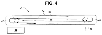
各ヒートパイプ24は、排気16から熱エネルギーを除去しかつ熱エネルギーを大気に放散させるように構成されかつ配置される。図4には、ヒートパイプ24の断面図を示している。ヒートパイプは、該ヒートパイプ24の外面を形成したケーシング34を含む。ケーシング34の内側には、吸収剤ウィック36が配置され、吸収剤ウィック36は、蒸気空洞38を囲む。水、ナトリウム又はその他の物質のような流体が、蒸気空洞38内に配置される。ヒートパイプ24の高温端部40が、排気16が該高温端部40を横切って流れるように配置される一方、低温端部42が、排気16の外側に配置される。高温端部40では、排気16からの熱エネルギーがヒートパイプ24に伝達され、高温端部40でウィック36内の流体を蒸気空洞38内への蒸気に蒸発させる。蒸気は、蒸気空洞38に沿って低温端部42に移動する。蒸気は、低温端部42内において液化されかつウィック36によって吸収されて、熱エネルギーを放出する。熱エネルギーは、低温端部42に配置されかつ該低温端部42にわたって強制的に空気を流す1以上のファン44によって大気に放散される。流体は、ウィック36を介して高温端部40に移動する。
Each
図5に示すような幾つかの実施形態では、各ヒートパイプ24は、固体ヒートパイプであり、固体ヒートパイプでは、排気16の熱エネルギーが空洞38内に配置された高熱伝導性固体媒体46によって吸収される。熱エネルギーは、固体媒体46を介して高温端部40から低温端部42に移動しかつ1以上のファン44によって大気に放散される。
In some embodiments, such as shown in FIG. 5, each
幾つかの実施形態では、ガスタービン10から排気ダクト18に流入する排気16の温度は、約1000〜1200°Fである。ヒートパイプアレイ32は、排気16がSCR系22に流入する前に該排気16の温度を800〜900°Fに低下させるように構成される。排気16の温度をそのような範囲に低下させることは、排気筒20を通して排気16を放出する前に該排気からNOxを除去する上でのSCR系22の有効性を高める。さらに、ヒートパイプ24のアレイ32を介して排気16を冷却することは、温度及び速度が一定である排気16をSCR系22に供給して、該SCR系22の効率が向上するようにする。
In some embodiments, the temperature of the
限られた数の実施形態のみに関して本発明を詳細に説明してきたが、本発明がそのような開示した実施形態に限定されるものではないことは、容易に理解される筈である。むしろ、本発明は、これまで説明していないが本発明の技術思想及び技術的範囲に相応するあらゆる多数の変形形態、変更形態、代替形態又は均等な構成を組込むように修正することができる。加えて、本発明の様々な実施形態を説明してきたが、本発明の態様は、記載した実施形態の幾つかだけを含むことができることを理解されたい。従って、本発明は、前述の説明によって限定されると見なすべきではなく、特許請求の範囲によってのみ限定される。 Although the invention has been described in detail with respect to only a limited number of embodiments, it should be readily understood that the invention is not limited to such disclosed embodiments. Rather, the invention can be modified to incorporate any number of variations, alterations, alternatives or equivalent arrangements not heretofore described, but which are commensurate with the spirit and scope of the invention. In addition, while various embodiments of the invention have been described, it is to be understood that aspects of the invention can include only some of the described embodiments. Accordingly, the invention is not to be seen as limited by the foregoing description, but is only limited by the scope of the appended claims.
10 ガスタービン
12 燃焼器
14 タービン
16 排気
18 排気ダクト
20 排気筒
22 選択触媒還元(SCR)系
24 ヒートパイプ
26 SCRダクト
28 横列
30 縦列
32 アレイ
34 ケーシング
36 ウィック
38 蒸気空洞
40 高温端部
42 低温端部
44 ファン
46 固体媒体
DESCRIPTION OF
Claims (10)
前記排気(16)から規制物質を除去することができる少なくとも1つの排気処理装置(22)と、
前記少なくとも1つの排気処理装置(22)の上流で少なくとも部分的に前記排気通路(18)内に配置された複数のヒートパイプ(24)と
を含むターボ機械であって、前記複数のヒートパイプ(24)が、前記排気(16)から該複数のヒートパイプ(24)に熱エネルギーを伝達させ、該排気(16)の温度を低下させて前記少なくとも1つの排気処理装置の有効性を高めることができる、ターボ機械(10)。 At least one exhaust passage (18) for directing and releasing exhaust (16) along it;
At least one exhaust treatment device (22) capable of removing regulated substances from the exhaust (16);
A turbomachine including a plurality of heat pipes (24) disposed at least partially in the exhaust passage (18) upstream of the at least one exhaust treatment device (22), the plurality of heat pipes ( 24) may transfer thermal energy from the exhaust (16) to the plurality of heat pipes (24) to reduce the temperature of the exhaust (16) to increase the effectiveness of the at least one exhaust treatment device. Can turbomachine (10).
少なくとも1つの排気通路(18)に沿って前記排気(16)を流すステップと、
複数のヒートパイプ(24)を通過させて前記排気(16)を流すステップと、
前記排気(16)から前記複数のヒートパイプ(24)に熱エネルギーを伝達させ、従って該排気(16)の温度を低下させるステップと、
少なくとも1つの排気処理装置(22)を通して前記排気(16)を流すステップと、
前記少なくとも1つの排気処理装置(22)を介して前記排気(16)から規制物質を除去するステップと、
前記排気(16)を放免するステップと
を含む方法。 A turbomachine (10) method for discharging exhaust (16),
Flowing the exhaust (16) along at least one exhaust passage (18);
Flowing the exhaust (16) through a plurality of heat pipes (24);
Transferring thermal energy from the exhaust (16) to the plurality of heat pipes (24), thus reducing the temperature of the exhaust (16);
Flowing the exhaust (16) through at least one exhaust treatment device (22);
Removing regulated substances from the exhaust (16) via the at least one exhaust treatment device (22);
Releasing the exhaust (16).
Applications Claiming Priority (2)
| Application Number | Priority Date | Filing Date | Title |
|---|---|---|---|
| US12/175,966 | 2008-07-18 | ||
| US12/175,966 US8596073B2 (en) | 2008-07-18 | 2008-07-18 | Heat pipe for removing thermal energy from exhaust gas |
Publications (2)
| Publication Number | Publication Date |
|---|---|
| JP2010025108A true JP2010025108A (en) | 2010-02-04 |
| JP5903202B2 JP5903202B2 (en) | 2016-04-13 |
Family
ID=40933794
Family Applications (1)
| Application Number | Title | Priority Date | Filing Date |
|---|---|---|---|
| JP2009166228A Expired - Fee Related JP5903202B2 (en) | 2008-07-18 | 2009-07-15 | Turbomachine with heat pipe for removing thermal energy from exhaust gas and exhaust method |
Country Status (4)
| Country | Link |
|---|---|
| US (1) | US8596073B2 (en) |
| EP (1) | EP2146075A3 (en) |
| JP (1) | JP5903202B2 (en) |
| CN (1) | CN101629516B (en) |
Families Citing this family (27)
| Publication number | Priority date | Publication date | Assignee | Title |
|---|---|---|---|---|
| US8516786B2 (en) * | 2009-08-13 | 2013-08-27 | General Electric Company | System and method for injection of cooling air into exhaust gas flow |
| US8973650B2 (en) * | 2010-07-20 | 2015-03-10 | General Electric Company | Superconductive heat transfer system |
| AT511051B1 (en) * | 2011-01-27 | 2013-01-15 | Ge Jenbacher Gmbh & Co Ohg | CATALYST ARRANGEMENT FOR AN EXHAUST GAS CLEANING DEVICE FOR AN INTERNAL COMBUSTION ENGINE |
| US8746975B2 (en) | 2011-02-17 | 2014-06-10 | Media Lario S.R.L. | Thermal management systems, assemblies and methods for grazing incidence collectors for EUV lithography |
| US8731139B2 (en) | 2011-05-04 | 2014-05-20 | Media Lario S.R.L. | Evaporative thermal management of grazing incidence collectors for EUV lithography |
| WO2014039039A1 (en) * | 2012-09-06 | 2014-03-13 | Hideo Miyanishi | Combustion gas cooling apparatus, denitration apparatus having the combustion gas cooling apparatus, and combustion gas cooling method |
| CN103195576B (en) * | 2013-03-25 | 2015-05-20 | 哈尔滨工程大学 | Infrared inhibiting device for smoke extraction of gas turbines of ships |
| US20150300261A1 (en) * | 2014-04-17 | 2015-10-22 | General Electric Company | Fuel heating system for use with a combined cycle gas turbine |
| JP6282184B2 (en) * | 2014-06-19 | 2018-02-21 | 三菱日立パワーシステムズ株式会社 | Heat transfer device and gas turbine combustor including the same |
| CN104632461B (en) * | 2015-02-04 | 2016-02-10 | 山东大学 | The vehicle exhaust heat exchanger that a kind of heat exchange amount is controlled and method of work thereof |
| US20160290214A1 (en) * | 2015-04-02 | 2016-10-06 | General Electric Company | Heat pipe cooled turbine casing system for clearance management |
| US20160290235A1 (en) * | 2015-04-02 | 2016-10-06 | General Electric Company | Heat pipe temperature management system for a turbomachine |
| US10598094B2 (en) | 2015-04-02 | 2020-03-24 | General Electric Company | Heat pipe temperature management system for wheels and buckets in a turbomachine |
| US9797310B2 (en) | 2015-04-02 | 2017-10-24 | General Electric Company | Heat pipe temperature management system for a turbomachine |
| US9644512B2 (en) * | 2015-05-05 | 2017-05-09 | Cummins Emission Solutions, Inc. | Dosing module with integrated heat pipe |
| US10005016B2 (en) | 2015-12-28 | 2018-06-26 | General Electric Company | Hydrophobic filtration of tempering air |
| CN105626265B (en) * | 2015-12-30 | 2017-04-19 | 中国航空工业集团公司沈阳发动机设计研究所 | Intercooling and backheating system of gas turbine |
| US10450929B2 (en) | 2016-01-20 | 2019-10-22 | General Electric Company | Anti-icing system and method for gas turbine exhaust sections |
| US10092878B2 (en) | 2016-03-03 | 2018-10-09 | General Electric Company | System and method for mixing tempering air with flue gas for hot SCR catalyst |
| US10883387B2 (en) | 2016-03-07 | 2021-01-05 | General Electric Company | Gas turbine exhaust diffuser with air injection |
| US10385779B2 (en) | 2016-06-07 | 2019-08-20 | General Electric Company | System for cooling exhaust gas with absorption chiller |
| US20170356319A1 (en) * | 2016-06-09 | 2017-12-14 | General Electric Company | Exhaust Gas Heat Exchange for Ammonia Evaporation Using a Heat Pipe |
| CN105952519A (en) * | 2016-07-16 | 2016-09-21 | 李陶胜 | Internal combustion engine air intake and exhaust system purification device |
| US10309242B2 (en) * | 2016-08-10 | 2019-06-04 | General Electric Company | Ceramic matrix composite component cooling |
| US10450957B2 (en) * | 2017-01-23 | 2019-10-22 | United Technologies Corporation | Gas turbine engine with heat pipe system |
| KR102598538B1 (en) * | 2018-10-22 | 2023-11-03 | 현대자동차주식회사 | Exhaust tail trim for vehicle |
| CN109989811A (en) * | 2019-05-14 | 2019-07-09 | 河北工业大学 | A kind of intermediate medium type exhaust gases of internal combustion engines temperature difference electricity generation device |
Citations (14)
| Publication number | Priority date | Publication date | Assignee | Title |
|---|---|---|---|---|
| JPS4893809A (en) * | 1972-03-17 | 1973-12-04 | ||
| JPS492041U (en) * | 1972-04-06 | 1974-01-09 | ||
| JPS56141039A (en) * | 1980-04-07 | 1981-11-04 | Nissan Motor Co Ltd | Recovering device of heat from exhaust gas |
| JPS6212717U (en) * | 1985-07-08 | 1987-01-26 | ||
| JPH01119330A (en) * | 1987-11-02 | 1989-05-11 | Ishikawajima Harima Heavy Ind Co Ltd | Denitration of exhaust gas from gas turbine |
| JPH0193358U (en) * | 1987-12-14 | 1989-06-20 | ||
| JPH06108877A (en) * | 1992-09-25 | 1994-04-19 | Mitsubishi Heavy Ind Ltd | Gas turbine single power generation system |
| JPH08293315A (en) * | 1995-04-21 | 1996-11-05 | Toshiba Corp | Desulfurizer for fuel cell generating device |
| JPH1193694A (en) * | 1997-09-18 | 1999-04-06 | Toshiba Corp | Gas turbine plant |
| US5918555A (en) * | 1996-04-19 | 1999-07-06 | Winegar; Phillip | Catalytic method for NOX reduction |
| JP2002501599A (en) * | 1996-10-25 | 2002-01-15 | ク,ユズイ | Superconducting heat transfer medium |
| JP2002071090A (en) * | 2000-08-31 | 2002-03-08 | Ishikawajima Harima Heavy Ind Co Ltd | Oil tank equipped with cooler for minimum flow |
| JP2005069161A (en) * | 2003-08-27 | 2005-03-17 | Toyota Motor Corp | Exhaust emission control device of internal combustion engine |
| JP2007064228A (en) * | 2005-09-01 | 2007-03-15 | General Electric Co <Ge> | Device operating gas turbine engine |
Family Cites Families (53)
| Publication number | Priority date | Publication date | Assignee | Title |
|---|---|---|---|---|
| DE294483C (en) | ||||
| US3517730A (en) * | 1967-03-15 | 1970-06-30 | Us Navy | Controllable heat pipe |
| US3722797A (en) * | 1970-11-04 | 1973-03-27 | Cci Aerospace Corp | Convergent divergent ejector exhaust nozzle |
| US4036290A (en) * | 1972-01-24 | 1977-07-19 | Kelly Donald A | Helical expansion condenser |
| US3852805A (en) * | 1973-06-18 | 1974-12-03 | Gen Electric | Heat-pipe cooled power semiconductor device assembly having integral semiconductor device evaporating surface unit |
| GB1446750A (en) * | 1973-12-20 | 1976-08-18 | Plessey Co Ltd | Engines having heat re-cycling means |
| US4033406A (en) * | 1974-09-03 | 1977-07-05 | Hughes Aircraft Company | Heat exchanger utilizing heat pipes |
| US4372110A (en) * | 1976-02-13 | 1983-02-08 | Nasa | Noise suppressor for turbo fan jet engines |
| US4149588A (en) * | 1976-03-15 | 1979-04-17 | Mcdonnell Douglas Corporation | Dry cooling system |
| US4621681A (en) * | 1977-11-09 | 1986-11-11 | Q-Dot Corporation | Waste heat boiler |
| US4234782A (en) * | 1978-01-19 | 1980-11-18 | Saskatchewan Power Corporation | Space heating using off-peak electric heat storage |
| US4226282A (en) * | 1978-08-30 | 1980-10-07 | Foster Wheeler Energy Corporation | Heat exchange apparatus utilizing thermal siphon pipes |
| US4280554A (en) * | 1980-02-04 | 1981-07-28 | The Air Preheater Company, Inc. | Heat tube |
| US4567857A (en) * | 1980-02-26 | 1986-02-04 | The United States Of America As Represented By The Administrator Of The National Aeronautics And Space Administration | Combustion engine system |
| US4426959A (en) * | 1980-07-01 | 1984-01-24 | Q-Dot Corporation | Waste heat recovery system having thermal sleeve support for heat pipe |
| US6866092B1 (en) * | 1981-02-19 | 2005-03-15 | Stephen Molivadas | Two-phase heat-transfer systems |
| US4381817A (en) | 1981-04-27 | 1983-05-03 | Foster Wheeler Energy Corporation | Wet/dry steam condenser |
| US4570466A (en) * | 1983-09-09 | 1986-02-18 | Laser Products Corporation | Door locking methods and apparatus |
| US4932204A (en) * | 1989-04-03 | 1990-06-12 | Westinghouse Electric Corp. | Efficiency combined cycle power plant |
| CN2110932U (en) | 1992-01-18 | 1992-07-22 | 李宗祥 | Heat absorption type cooling arrangement |
| US5248252A (en) * | 1992-06-30 | 1993-09-28 | Gas Research Institute | Enhanced radiant output burner |
| US5237939A (en) * | 1992-08-20 | 1993-08-24 | Wahlco Environmental Systems, Inc. | Method and apparatus for reducing NOx emissions |
| US5233934A (en) * | 1992-08-20 | 1993-08-10 | Wahlco Environmental Systems, Inc. | Control of NOx reduction in flue gas flows |
| US5311930A (en) * | 1992-11-17 | 1994-05-17 | Bruenn Paul R | Heat reclamation device |
| US5632143A (en) * | 1994-06-14 | 1997-05-27 | Ormat Industries Ltd. | Gas turbine system and method using temperature control of the exhaust gas entering the heat recovery cycle by mixing with ambient air |
| DE19512466C1 (en) * | 1995-04-03 | 1996-08-22 | Siemens Ag | Steam generator operating method for gas and steam turbine plant |
| EP0794401A3 (en) | 1996-03-06 | 1998-09-23 | Hudson Products Corporation | Steam condensing apparatus |
| US6916430B1 (en) * | 1996-10-25 | 2005-07-12 | New Qu Energy Ltd. | Superconducting heat transfer medium |
| US5845481A (en) * | 1997-01-24 | 1998-12-08 | Westinghouse Electric Corporation | Combustion turbine with fuel heating system |
| US6065280A (en) * | 1998-04-08 | 2000-05-23 | General Electric Co. | Method of heating gas turbine fuel in a combined cycle power plant using multi-component flow mixtures |
| US6241009B1 (en) * | 2000-02-07 | 2001-06-05 | Hudson Products Corporation | Integrated heat pipe vent condenser |
| US6397575B2 (en) * | 2000-03-23 | 2002-06-04 | General Electric Company | Apparatus and methods of reheating gas turbine cooling steam and high pressure steam turbine exhaust in a combined cycle power generating system |
| EP1193373A1 (en) * | 2000-09-29 | 2002-04-03 | Siemens Aktiengesellschaft | Method of operating a gas and steam turbine plant and corresponding plant |
| US20030182944A1 (en) * | 2002-04-02 | 2003-10-02 | Hoffman John S. | Highly supercharged gas-turbine generating system |
| US7069716B1 (en) * | 2002-04-24 | 2006-07-04 | Express Integrated Technologies Llc | Cooling air distribution apparatus |
| US6782703B2 (en) * | 2002-09-11 | 2004-08-31 | Siemens Westinghouse Power Corporation | Apparatus for starting a combined cycle power plant |
| US6962051B2 (en) * | 2003-06-17 | 2005-11-08 | Utc Power, Llc | Control of flow through a vapor generator |
| US7131294B2 (en) * | 2004-01-13 | 2006-11-07 | Tecumseh Products Company | Method and apparatus for control of carbon dioxide gas cooler pressure by use of a capillary tube |
| GB2414690A (en) * | 2004-06-04 | 2005-12-07 | Ford Global Tech Llc | An emission control apparatus for an engine |
| JP2006090156A (en) * | 2004-09-21 | 2006-04-06 | Shin Caterpillar Mitsubishi Ltd | Method for regenerating waste heat energy and waste heat energy regenerating device |
| US20060083626A1 (en) * | 2004-10-19 | 2006-04-20 | Manole Dan M | Compressor and hermetic housing with minimal housing ports |
| JP2006284144A (en) * | 2005-04-04 | 2006-10-19 | Denso Corp | Exhaust heat recovery device |
| JP2006317013A (en) * | 2005-04-12 | 2006-11-24 | Denso Corp | Heat pipe and waste heat recovering device using the same |
| US20070017207A1 (en) * | 2005-07-25 | 2007-01-25 | General Electric Company | Combined Cycle Power Plant |
| US7730727B2 (en) * | 2005-09-06 | 2010-06-08 | American Air Liquide, Inc. | Flexible flow control device for cogeneration ducting applications |
| US7523602B2 (en) * | 2005-09-27 | 2009-04-28 | United Technologies Corporation | Turbine exhaust catalyst |
| EP1801241A1 (en) * | 2005-12-23 | 2007-06-27 | Paul Wurth S.A. | A rotary charging device for a shaft furnace equipped with a cooling system |
| US7382047B2 (en) * | 2005-12-27 | 2008-06-03 | Fu Zhun Precision Industry (Shen Zhen) Co., Ltd. | Heat dissipation device |
| US7621720B2 (en) * | 2006-06-30 | 2009-11-24 | General Electric Company | Cooling device |
| US7584748B2 (en) | 2006-11-20 | 2009-09-08 | Gm Global Technology Operations, Inc. | Exhaust gas recirculation system for an internal combustion engine |
| US7784300B2 (en) * | 2006-12-22 | 2010-08-31 | Yiding Cao | Refrigerator |
| US20080164009A1 (en) * | 2007-01-07 | 2008-07-10 | Yong Chong | Direct Embedded Heat Pipe Apparatus |
| US8359824B2 (en) * | 2008-07-29 | 2013-01-29 | General Electric Company | Heat recovery steam generator for a combined cycle power plant |
-
2008
- 2008-07-18 US US12/175,966 patent/US8596073B2/en not_active Expired - Fee Related
-
2009
- 2009-07-13 EP EP09165356.8A patent/EP2146075A3/en not_active Withdrawn
- 2009-07-15 JP JP2009166228A patent/JP5903202B2/en not_active Expired - Fee Related
- 2009-07-16 CN CN200910161615.1A patent/CN101629516B/en not_active Expired - Fee Related
Patent Citations (14)
| Publication number | Priority date | Publication date | Assignee | Title |
|---|---|---|---|---|
| JPS4893809A (en) * | 1972-03-17 | 1973-12-04 | ||
| JPS492041U (en) * | 1972-04-06 | 1974-01-09 | ||
| JPS56141039A (en) * | 1980-04-07 | 1981-11-04 | Nissan Motor Co Ltd | Recovering device of heat from exhaust gas |
| JPS6212717U (en) * | 1985-07-08 | 1987-01-26 | ||
| JPH01119330A (en) * | 1987-11-02 | 1989-05-11 | Ishikawajima Harima Heavy Ind Co Ltd | Denitration of exhaust gas from gas turbine |
| JPH0193358U (en) * | 1987-12-14 | 1989-06-20 | ||
| JPH06108877A (en) * | 1992-09-25 | 1994-04-19 | Mitsubishi Heavy Ind Ltd | Gas turbine single power generation system |
| JPH08293315A (en) * | 1995-04-21 | 1996-11-05 | Toshiba Corp | Desulfurizer for fuel cell generating device |
| US5918555A (en) * | 1996-04-19 | 1999-07-06 | Winegar; Phillip | Catalytic method for NOX reduction |
| JP2002501599A (en) * | 1996-10-25 | 2002-01-15 | ク,ユズイ | Superconducting heat transfer medium |
| JPH1193694A (en) * | 1997-09-18 | 1999-04-06 | Toshiba Corp | Gas turbine plant |
| JP2002071090A (en) * | 2000-08-31 | 2002-03-08 | Ishikawajima Harima Heavy Ind Co Ltd | Oil tank equipped with cooler for minimum flow |
| JP2005069161A (en) * | 2003-08-27 | 2005-03-17 | Toyota Motor Corp | Exhaust emission control device of internal combustion engine |
| JP2007064228A (en) * | 2005-09-01 | 2007-03-15 | General Electric Co <Ge> | Device operating gas turbine engine |
Also Published As
| Publication number | Publication date |
|---|---|
| US8596073B2 (en) | 2013-12-03 |
| JP5903202B2 (en) | 2016-04-13 |
| US20100011738A1 (en) | 2010-01-21 |
| CN101629516B (en) | 2015-10-07 |
| EP2146075A3 (en) | 2017-05-17 |
| EP2146075A2 (en) | 2010-01-20 |
| CN101629516A (en) | 2010-01-20 |
Similar Documents
| Publication | Publication Date | Title |
|---|---|---|
| JP5903202B2 (en) | Turbomachine with heat pipe for removing thermal energy from exhaust gas and exhaust method | |
| JP5825759B2 (en) | Apparatus and method for cooling a turbine using a heat pipe | |
| JP2010025107A (en) | Device and method for cooling turbomachine exhaust gas | |
| US11168583B2 (en) | Systems and methods for cooling components within a gas turbine engine | |
| JP5752367B2 (en) | System and method for injecting cooling air into an exhaust gas stream | |
| US7748211B2 (en) | Vapor cooling of detonation engines | |
| EP3214278B1 (en) | System and method for mixing tempering air with flue gas for hot scr catalyst | |
| ES2901678T3 (en) | Organic Rankine cycle system and method | |
| JP2010196708A (en) | Method and apparatus for operation of co/voc oxidation catalyst to reduce no2 formation for gas turbine | |
| TW201035494A (en) | Heat exchanger | |
| JP2008534844A (en) | Fuel carrying member with heat pipe | |
| JP2016079976A (en) | Media pads with built-in mist elimination features | |
| US20140026751A1 (en) | System and method for capturing carbon dioxide from flue gas | |
| JP6960736B2 (en) | Ice protection system for gas turbines | |
| US20170356319A1 (en) | Exhaust Gas Heat Exchange for Ammonia Evaporation Using a Heat Pipe | |
| JP7091312B2 (en) | Ammonia injection regulation for gas turbine selective catalytic reduction system | |
| JP6417167B2 (en) | gas turbine | |
| JP5099967B2 (en) | Method and apparatus for operating a gas turbine engine | |
| US20170350320A1 (en) | System for Cooling Exhaust Gas with Absorption Chiller | |
| US7954324B2 (en) | Gas turbine engine | |
| JP2013160406A (en) | Dew condensation preventing device for exhaust in latent heat recovery type combustion apparatus | |
| JP5448938B2 (en) | Gas turbine intake system and gas turbine equipped with the same | |
| CN105509514A (en) | Fin tube type gas-liquid heat exchanger | |
| US20110262265A1 (en) | Installation having a thermal transfer arrangement | |
| JP6155114B2 (en) | Gas turbine intake cooling system and gas turbine equipment |
Legal Events
| Date | Code | Title | Description |
|---|---|---|---|
| A621 | Written request for application examination |
Free format text: JAPANESE INTERMEDIATE CODE: A621 Effective date: 20120711 |
|
| A131 | Notification of reasons for refusal |
Free format text: JAPANESE INTERMEDIATE CODE: A131 Effective date: 20130625 |
|
| A977 | Report on retrieval |
Free format text: JAPANESE INTERMEDIATE CODE: A971007 Effective date: 20130628 |
|
| A601 | Written request for extension of time |
Free format text: JAPANESE INTERMEDIATE CODE: A601 Effective date: 20130925 |
|
| A602 | Written permission of extension of time |
Free format text: JAPANESE INTERMEDIATE CODE: A602 Effective date: 20130930 |
|
| A601 | Written request for extension of time |
Free format text: JAPANESE INTERMEDIATE CODE: A601 Effective date: 20131024 |
|
| A602 | Written permission of extension of time |
Free format text: JAPANESE INTERMEDIATE CODE: A602 Effective date: 20131029 |
|
| A601 | Written request for extension of time |
Free format text: JAPANESE INTERMEDIATE CODE: A601 Effective date: 20131122 |
|
| A602 | Written permission of extension of time |
Free format text: JAPANESE INTERMEDIATE CODE: A602 Effective date: 20131127 |
|
| A521 | Written amendment |
Free format text: JAPANESE INTERMEDIATE CODE: A523 Effective date: 20131224 |
|
| A131 | Notification of reasons for refusal |
Free format text: JAPANESE INTERMEDIATE CODE: A131 Effective date: 20140603 |
|
| A601 | Written request for extension of time |
Free format text: JAPANESE INTERMEDIATE CODE: A601 Effective date: 20140902 |
|
| A602 | Written permission of extension of time |
Free format text: JAPANESE INTERMEDIATE CODE: A602 Effective date: 20140905 |
|
| A601 | Written request for extension of time |
Free format text: JAPANESE INTERMEDIATE CODE: A601 Effective date: 20141002 |
|
| A602 | Written permission of extension of time |
Free format text: JAPANESE INTERMEDIATE CODE: A602 Effective date: 20141007 |
|
| A601 | Written request for extension of time |
Free format text: JAPANESE INTERMEDIATE CODE: A601 Effective date: 20141031 |
|
| A602 | Written permission of extension of time |
Free format text: JAPANESE INTERMEDIATE CODE: A602 Effective date: 20141106 |
|
| A02 | Decision of refusal |
Free format text: JAPANESE INTERMEDIATE CODE: A02 Effective date: 20150707 |
|
| A521 | Written amendment |
Free format text: JAPANESE INTERMEDIATE CODE: A523 Effective date: 20151106 |
|
| A911 | Transfer of reconsideration by examiner before appeal (zenchi) |
Free format text: JAPANESE INTERMEDIATE CODE: A911 Effective date: 20151222 |
|
| A131 | Notification of reasons for refusal |
Free format text: JAPANESE INTERMEDIATE CODE: A131 Effective date: 20160126 |
|
| A521 | Written amendment |
Free format text: JAPANESE INTERMEDIATE CODE: A523 Effective date: 20160128 |
|
| TRDD | Decision of grant or rejection written | ||
| A01 | Written decision to grant a patent or to grant a registration (utility model) |
Free format text: JAPANESE INTERMEDIATE CODE: A01 Effective date: 20160216 |
|
| A61 | First payment of annual fees (during grant procedure) |
Free format text: JAPANESE INTERMEDIATE CODE: A61 Effective date: 20160314 |
|
| R150 | Certificate of patent or registration of utility model |
Ref document number: 5903202 Country of ref document: JP Free format text: JAPANESE INTERMEDIATE CODE: R150 |
|
| LAPS | Cancellation because of no payment of annual fees |