JP2010023177A - 空気圧工具 - Google Patents
空気圧工具 Download PDFInfo
- Publication number
- JP2010023177A JP2010023177A JP2008187152A JP2008187152A JP2010023177A JP 2010023177 A JP2010023177 A JP 2010023177A JP 2008187152 A JP2008187152 A JP 2008187152A JP 2008187152 A JP2008187152 A JP 2008187152A JP 2010023177 A JP2010023177 A JP 2010023177A
- Authority
- JP
- Japan
- Prior art keywords
- cylinder
- main valve
- striking
- seal
- air
- Prior art date
- Legal status (The legal status is an assumption and is not a legal conclusion. Google has not performed a legal analysis and makes no representation as to the accuracy of the status listed.)
- Granted
Links
Images


Abstract
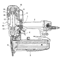
【解決手段】高圧エアを貯留したエアチャンバと、打撃手段と一体に結合した打撃ピストン11を摺動自在に収容した打撃シリンダ10と、上下動によってエアチャンバ内の圧縮エアを打撃シリンダ10内に開閉するメインバルブ8とを備えた空気圧工具において、上記打撃シリンダ10の外周に弾性を有するシリンダシール22を設け、このシリンダシール22に上記メインバルブ8を当接離間することによってエアチャンバ内の高圧エアを打撃シリンダ10に対して開閉させるとともに、上記打撃シリンダ10の上記シリンダシール22の背面側には、上記メインバルブ8の開き作動時に上記エアチャンバから上記シリンダシール22の背面側に回りこんだ圧縮エアを打撃シリンダ10内に排出する小穴28を貫通形成した。
【選択図】図3
Description
8 メインバルブ
10 打撃シリンダ
22 シリンダシール
24 環状突縁
28 小穴
Claims (2)
- 高圧エアを貯留したエアチャンバと、打撃手段と一体に結合した打撃ピストンを摺動自在に収容した打撃シリンダと、上下動によってエアチャンバ内の圧縮エアを打撃シリンダ内に開閉するメインバルブとを備えた空気圧工具において、
上記打撃シリンダの外周に弾性を有するシリンダシールを設け、このシリンダシールに上記メインバルブを当接離間することによってエアチャンバ内の高圧エアを打撃シリンダに対して開閉させるとともに、
上記打撃シリンダの上記シリンダシールの背面側には、上記メインバルブの開き作動時に上記エアチャンバから上記シリンダシールの背面側に回りこんだ圧縮エアを打撃シリンダ内に排出する小穴を貫通形成した
ことを特徴とする空気圧工具。 - 上記シリンダシールは打撃シリンダの外周に形成された環状突縁に取り付けられていることを特徴とする、請求項1に記載の空気圧工具。
Priority Applications (1)
| Application Number | Priority Date | Filing Date | Title |
|---|---|---|---|
| JP2008187152A JP5071287B2 (ja) | 2008-07-18 | 2008-07-18 | 空気圧工具 |
Applications Claiming Priority (1)
| Application Number | Priority Date | Filing Date | Title |
|---|---|---|---|
| JP2008187152A JP5071287B2 (ja) | 2008-07-18 | 2008-07-18 | 空気圧工具 |
Publications (2)
| Publication Number | Publication Date |
|---|---|
| JP2010023177A true JP2010023177A (ja) | 2010-02-04 |
| JP5071287B2 JP5071287B2 (ja) | 2012-11-14 |
Family
ID=41729496
Family Applications (1)
| Application Number | Title | Priority Date | Filing Date |
|---|---|---|---|
| JP2008187152A Active JP5071287B2 (ja) | 2008-07-18 | 2008-07-18 | 空気圧工具 |
Country Status (1)
| Country | Link |
|---|---|
| JP (1) | JP5071287B2 (ja) |
Cited By (1)
| Publication number | Priority date | Publication date | Assignee | Title |
|---|---|---|---|---|
| JP2017042847A (ja) * | 2015-08-24 | 2017-03-02 | マックス株式会社 | 打込み工具 |
Families Citing this family (1)
| Publication number | Priority date | Publication date | Assignee | Title |
|---|---|---|---|---|
| CN103707266B (zh) * | 2014-01-10 | 2015-07-22 | 浙江荣鹏气动工具有限公司 | 气动钉枪 |
Citations (4)
| Publication number | Priority date | Publication date | Assignee | Title |
|---|---|---|---|---|
| JPS6250070U (ja) * | 1985-04-22 | 1987-03-27 | ||
| US20040020964A1 (en) * | 2002-07-30 | 2004-02-05 | Yun-Chung Lee | Rotary cover head of nail gun |
| JP2007021693A (ja) * | 2005-07-20 | 2007-02-01 | Max Co Ltd | 打込み工具の低全高構造 |
| JP2008110469A (ja) * | 2006-10-30 | 2008-05-15 | De Poan Pneumatic Corp | エアードライバー |
-
2008
- 2008-07-18 JP JP2008187152A patent/JP5071287B2/ja active Active
Patent Citations (4)
| Publication number | Priority date | Publication date | Assignee | Title |
|---|---|---|---|---|
| JPS6250070U (ja) * | 1985-04-22 | 1987-03-27 | ||
| US20040020964A1 (en) * | 2002-07-30 | 2004-02-05 | Yun-Chung Lee | Rotary cover head of nail gun |
| JP2007021693A (ja) * | 2005-07-20 | 2007-02-01 | Max Co Ltd | 打込み工具の低全高構造 |
| JP2008110469A (ja) * | 2006-10-30 | 2008-05-15 | De Poan Pneumatic Corp | エアードライバー |
Cited By (2)
| Publication number | Priority date | Publication date | Assignee | Title |
|---|---|---|---|---|
| JP2017042847A (ja) * | 2015-08-24 | 2017-03-02 | マックス株式会社 | 打込み工具 |
| US10525574B2 (en) | 2015-08-24 | 2020-01-07 | Max Co., Ltd. | Driving tool |
Also Published As
| Publication number | Publication date |
|---|---|
| JP5071287B2 (ja) | 2012-11-14 |
Similar Documents
| Publication | Publication Date | Title |
|---|---|---|
| TWI399270B (zh) | 扣件驅動工具 | |
| WO2016002540A1 (ja) | 打込機 | |
| JP5310311B2 (ja) | 衝撃工具用バンパ及び衝撃工具 | |
| JP4687572B2 (ja) | 打込機 | |
| WO2006019075A1 (ja) | 圧縮空気釘打機のメインバルブ機構 | |
| JP4752751B2 (ja) | 打込機 | |
| WO2007010959A1 (ja) | 打ち込み工具 | |
| JP5071287B2 (ja) | 空気圧工具 | |
| JP4481229B2 (ja) | 固着具打込装置 | |
| JP5748104B2 (ja) | 打込機 | |
| JP5023816B2 (ja) | 打込み工具 | |
| JPH091475A (ja) | 空気圧式固着具打込機 | |
| JP4434848B2 (ja) | 打込力切換え可能な固着具打込装置 | |
| JP2017119330A (ja) | 打込機 | |
| JP3948349B2 (ja) | 空気釘打機 | |
| JPH0521718B2 (ja) | ||
| JP3687593B2 (ja) | 圧縮空気駆動衝撃工具の打撃ピストン保持機構 | |
| JPH08276374A (ja) | 単発連続打ち切替機構を有する打込機 | |
| JP4569520B2 (ja) | 打込機 | |
| JP2006218585A (ja) | 釘打機 | |
| JP6540235B2 (ja) | 打込機 | |
| JPH09141570A (ja) | 空気圧式釘打機における排気機構 | |
| JP4569521B2 (ja) | 打込機 | |
| JPH09109056A (ja) | 空気圧式釘打機におけるピストンとドライバとの取付構造 | |
| JP2001353671A (ja) | 空気圧工具のバンパ機構 |
Legal Events
| Date | Code | Title | Description |
|---|---|---|---|
| A621 | Written request for application examination |
Free format text: JAPANESE INTERMEDIATE CODE: A621 Effective date: 20100922 |
|
| TRDD | Decision of grant or rejection written | ||
| A01 | Written decision to grant a patent or to grant a registration (utility model) |
Free format text: JAPANESE INTERMEDIATE CODE: A01 Effective date: 20120724 |
|
| A01 | Written decision to grant a patent or to grant a registration (utility model) |
Free format text: JAPANESE INTERMEDIATE CODE: A01 |
|
| A61 | First payment of annual fees (during grant procedure) |
Free format text: JAPANESE INTERMEDIATE CODE: A61 Effective date: 20120806 |
|
| R150 | Certificate of patent or registration of utility model |
Ref document number: 5071287 Country of ref document: JP Free format text: JAPANESE INTERMEDIATE CODE: R150 Free format text: JAPANESE INTERMEDIATE CODE: R150 |
|
| FPAY | Renewal fee payment (event date is renewal date of database) |
Free format text: PAYMENT UNTIL: 20150831 Year of fee payment: 3 |