JP2009228886A - Vacuum heat insulating material and heat insulating box using the same - Google Patents
Vacuum heat insulating material and heat insulating box using the same Download PDFInfo
- Publication number
- JP2009228886A JP2009228886A JP2008078562A JP2008078562A JP2009228886A JP 2009228886 A JP2009228886 A JP 2009228886A JP 2008078562 A JP2008078562 A JP 2008078562A JP 2008078562 A JP2008078562 A JP 2008078562A JP 2009228886 A JP2009228886 A JP 2009228886A
- Authority
- JP
- Japan
- Prior art keywords
- heat insulating
- insulating material
- vacuum heat
- fiber
- fibers
- Prior art date
- Legal status (The legal status is an assumption and is not a legal conclusion. Google has not performed a legal analysis and makes no representation as to the accuracy of the status listed.)
- Pending
Links
Images


Classifications
-
- F—MECHANICAL ENGINEERING; LIGHTING; HEATING; WEAPONS; BLASTING
- F16—ENGINEERING ELEMENTS AND UNITS; GENERAL MEASURES FOR PRODUCING AND MAINTAINING EFFECTIVE FUNCTIONING OF MACHINES OR INSTALLATIONS; THERMAL INSULATION IN GENERAL
- F16L—PIPES; JOINTS OR FITTINGS FOR PIPES; SUPPORTS FOR PIPES, CABLES OR PROTECTIVE TUBING; MEANS FOR THERMAL INSULATION IN GENERAL
- F16L59/00—Thermal insulation in general
- F16L59/06—Arrangements using an air layer or vacuum
- F16L59/065—Arrangements using an air layer or vacuum using vacuum
-
- F—MECHANICAL ENGINEERING; LIGHTING; HEATING; WEAPONS; BLASTING
- F25—REFRIGERATION OR COOLING; COMBINED HEATING AND REFRIGERATION SYSTEMS; HEAT PUMP SYSTEMS; MANUFACTURE OR STORAGE OF ICE; LIQUEFACTION SOLIDIFICATION OF GASES
- F25D—REFRIGERATORS; COLD ROOMS; ICE-BOXES; COOLING OR FREEZING APPARATUS NOT OTHERWISE PROVIDED FOR
- F25D2201/00—Insulation
- F25D2201/10—Insulation with respect to heat
- F25D2201/14—Insulation with respect to heat using subatmospheric pressure
Landscapes
- Engineering & Computer Science (AREA)
- General Engineering & Computer Science (AREA)
- Mechanical Engineering (AREA)
- Thermal Insulation (AREA)
Abstract
Description
本発明は、真空断熱材及びこれを用いた断熱箱に関し、特に取り扱い性及び断熱性能に優れた真空断熱材及びこれを用いた断熱箱に関するものである。 The present invention relates to a vacuum heat insulating material and a heat insulating box using the same, and particularly to a vacuum heat insulating material excellent in handleability and heat insulating performance and a heat insulating box using the same.
従来から、冷蔵庫や冷凍庫、自動販売機、保冷庫、保温庫、保冷車、車両用空調機、給湯機などの冷熱機器の断熱箱に使用される断熱材としてウレタンフォームが多く利用されている。近年、省エネや省スペース大容量化などの市場の要請からウレタンフォームよりも断熱性能に優れている真空断熱材をウレタンフォーム中に埋設し、真空断熱材及びウレタンフォームを併用する形態が用いられるようになってきている。この真空断熱材とは、ガスバリア性のアルミ箔ラミネートフィルムなどで構成された外包材の中に粉末や発泡体、繊維体などを芯材として挿入し、その内部を数Pa(パスカル)の真空度に保つように構成されたものである。 Conventionally, urethane foam has been widely used as a heat insulating material used in a heat insulation box of a cooling device such as a refrigerator, a freezer, a vending machine, a cold storage, a heat storage, a cold storage vehicle, a vehicle air conditioner, and a water heater. In recent years, due to market demands such as energy saving and space saving, vacuum insulation material with better heat insulation performance than urethane foam is embedded in urethane foam, and a form using both vacuum insulation material and urethane foam is used. It is becoming. This vacuum heat insulating material is a powder, foam, fiber, etc. inserted into the outer packaging material composed of a gas barrier aluminum foil laminate film, etc., and the inside has a degree of vacuum of several Pa (Pascal) Is configured to keep
このような真空断熱材の取り扱い性及び断熱性能は、内部に挿入される芯材の材質に影響される。真空断熱材の芯材としては、シリカなどの粉末やウレタンなどの発泡体、繊維の集合体(繊維体)が多く利用されている。このうち繊維の素材には、ガラス繊維やセラミック繊維などの無機繊維(たとえば、特許文献1及び8参照)、あるいはポリプロピレン繊維やポリ乳酸繊維、アラミド繊維、LCP(液晶ポリマー)繊維、ポリエチレンテレフタレート繊維、ポリエステル繊維、ポリエチレン繊維、セルロース繊維などの有機繊維(たとえば、特許文献2及び7参照)が利用されている。
The handling property and heat insulation performance of such a vacuum heat insulating material are affected by the material of the core material inserted therein. As the core material of the vacuum heat insulating material, powders such as silica, foams such as urethane, and fiber aggregates (fiber bodies) are often used. Of these, the fiber material includes inorganic fibers such as glass fibers and ceramic fibers (for example, see Patent Documents 1 and 8), polypropylene fibers, polylactic acid fibers, aramid fibers, LCP (liquid crystal polymer) fibers, polyethylene terephthalate fibers, Organic fibers such as polyester fibers, polyethylene fibers, and cellulose fibers (see, for example,
その中でも、断熱性能に特に優れているガラス繊維の集合体を真空断熱材の芯材として利用することが主流になっている。そして、このような無機繊維あるいは有機繊維を集合させて繊維体を構成し、真空断熱材の芯材として利用している。繊維体の形状としては、たとえば綿状(繊維が不規則に絡み合って一体化されている状態)やシートを積層した形状(たとえば、特許文献3及び4参照)、シートを繊維配向が交互になるように積層した形状(たとえば、特許文献5及び6参照)などが開示されている。
Among them, it has become mainstream to use an aggregate of glass fibers that are particularly excellent in heat insulation performance as a core material of a vacuum heat insulating material. Then, such inorganic fibers or organic fibers are aggregated to form a fiber body, which is used as a core material of a vacuum heat insulating material. As the shape of the fibrous body, for example, cotton (a state in which fibers are intertwined irregularly and integrated), a shape in which sheets are laminated (for example, refer to
上述したように、現在の真空断熱材には、主に無機繊維であるガラス繊維が芯材として使用されている。このガラス繊維は、硬くて脆いという性質を有している。そのため、真空断熱材の製造時に粉塵が飛び散り、作業者の皮膚や粘膜などに付着することで、作業者が刺激を受ける可能性があり、その取り扱い性及び作業性が問題となっている。また、リサイクルの場面を考えた場合、たとえば冷蔵庫ではリサイクル工場で製品ごと粉砕され、ガラス繊維はウレタン屑などに混じってサーマルリサイクルに供されるが、燃焼効率を落としたり残渣となったりするなど、リサイクル効率が低いという欠点がある。 As described above, glass fibers, which are mainly inorganic fibers, are used as core materials in current vacuum heat insulating materials. This glass fiber is hard and brittle. For this reason, dust is scattered at the time of manufacturing the vacuum heat insulating material and adheres to the skin or mucous membrane of the worker, so that the worker may be stimulated, and the handling property and workability are problematic. Also, when considering the scene of recycling, for example, in the refrigerator, the product is pulverized together at the recycling factory, and the glass fiber is mixed with urethane waste and is used for thermal recycling. There is a disadvantage of low recycling efficiency.
一方、有機繊維であるポリエステル繊維等を芯材として使用した真空断熱材は、ガラス繊維を芯材として使用した真空断熱材に比べて、取り扱い性及びリサイクル性に優れているものの、断熱性能が劣るという欠点がある。つまり、ポリエステル繊維等を芯材として使用した真空断熱材は、断熱性能を表す指標である熱伝導率が0.0030[W/mK](特許文献7参照)程度であり、ガラス繊維を芯材として用いた一般的な真空断熱材の熱伝導率である0.0020[W/mK]に比べて大きく、断熱性能に劣っているということが理解できる。 On the other hand, the vacuum heat insulating material using organic fibers such as polyester fiber as the core material is inferior in heat insulating performance, although it is superior in handling property and recyclability compared to the vacuum heat insulating material using glass fiber as the core material. There is a drawback. That is, the vacuum heat insulating material using polyester fiber or the like as a core material has a thermal conductivity of about 0.0030 [W / mK] (see Patent Document 7), which is an index representing heat insulating performance, and glass fiber is used as the core material. As compared with 0.0020 [W / mK], which is the thermal conductivity of a general vacuum heat insulating material used as the above, it can be understood that the heat insulating performance is inferior.
本発明は、上記のような課題を解決するためになされたもので、取り扱い性及び断熱性能に優れた真空断熱材及びこれを用いた断熱箱を提供することを目的としている。 The present invention has been made to solve the above-described problems, and an object of the present invention is to provide a vacuum heat insulating material excellent in handleability and heat insulating performance and a heat insulating box using the same.
本発明に係る真空断熱材は、繊維集合体が積層されて構成された芯材と、ガスバリア性を有し、前記芯材を収容して内部が真空にされる外包材と、を備えたことを特徴とする。また、本発明に係る断熱箱は、上記の真空断熱材を用いたことを特徴とする。 The vacuum heat insulating material according to the present invention includes a core material formed by laminating fiber assemblies, and an outer packaging material that has gas barrier properties and accommodates the core material to be evacuated. It is characterized by. Moreover, the heat insulation box which concerns on this invention is characterized by using said vacuum heat insulating material.
本発明に係る真空断熱材によれば、繊維の配向方向を伝熱方向に略直角に配向することができるので、断熱性能を向上できる。また、本発明に係る断熱箱によれば、上記の断熱性能を向上できる真空断熱材を用いているので、同様に断熱性能に優れたものとなる。 According to the vacuum heat insulating material according to the present invention, since the fiber orientation direction can be oriented substantially perpendicular to the heat transfer direction, the heat insulation performance can be improved. Moreover, according to the heat insulation box which concerns on this invention, since the vacuum heat insulating material which can improve said heat insulation performance is used, it becomes the thing excellent in the heat insulation performance similarly.
以下、本発明の実施の形態を図面に基づいて説明する。
実施の形態1.
図1は、本発明の実施の形態1に係る真空断熱材100の断面構成を示す概略縦断面図である。図2は、真空断熱材100の概略構成を示す模式図である。図1及び図2に基づいて、真空断熱材100の構成について説明する。この真空断熱材100は、たとえば冷蔵庫や冷凍庫、自動販売機、保冷庫、保温庫、保冷車、車両用空調機、給湯機などの冷熱機器の断熱箱に用いられるものである。なお、図1を含め、以下の図面では各構成部材の大きさの関係が実際のものとは異なる場合がある。
Hereinafter, embodiments of the present invention will be described with reference to the drawings.
Embodiment 1 FIG.
FIG. 1 is a schematic longitudinal sectional view showing a sectional configuration of a vacuum
図1に示すように、真空断熱材100は、芯材3及び吸着剤2を外包材3に収容して構成されている。外包材1は、たとえばガスバリヤ層に約6μmのアルミ箔、最内層のシール層にポリエチレンを適用したプラスチックラミネートフィルムで構成するとよい。つまり、外包材1は、ガスバリア性を有し、内部を減圧状態に維持できるものであれば、どのような材質で構成してもよいのである。吸着剤2は、真空断熱材100の内部の水分を吸着し、真空断熱材100の内部における真空度の経時劣化を抑制するためのものである。この吸着剤2は、たとえばCaO(酸化カルシウム)を不織布袋に入れて構成するとよい。
As shown in FIG. 1, the vacuum
芯材3は、プラスチックラミネートフィルムを外包材1に用いる真空断熱材100において、大気圧を支えて真空断熱材100の内部空間を確保する役割と、内部空間を細かく分割してガスの熱伝導などを低減する役割と、を担うものである。この実施の形態1では、芯材3は、繊維集合体3aを多数重ねた多層構造となっている。このようにして、断熱方向である厚さ方向と、その厚さ方向と略垂直に配置される繊維の配向方向と、を整えるようになっている。なお、ガスの熱伝導抑制の観点では、真空断熱材100の内部空間の距離を、その真空度における空気分子の自由行程距離より小さくなるようにすることが望ましい。
The
図3は、芯材3の縦断面構成を拡大して示す概略図である。図3に基づいて、芯材3の構成について詳細に説明する。図3に示すように、芯材3は、繊維集合体3aの各層を、繊維が厚さ方向への重なりがないように一方向に配向した状態にし、上下に積層される各層とは繊維を略直交するように重ねることで構成されている。具体的には、芯材3は、紡糸した繊維を繊維どうしの重なりがないように一方向へ配向して並べて形成した繊維集合体3aを、繊維の方向が略直交するように交互に積層して形成されている。
FIG. 3 is an enlarged schematic view showing the configuration of the longitudinal section of the
繊維集合体3aの各層は、フィルムを延伸して分子配向させた後に、割り裂くようにして製造してもよい。このような方法を用いれば、フィルムを割り裂く際、繊維を完全に分離させずに、部分的に繊維間の連結部を残すようにすることができ、割り裂き後のシートを、繊維方向と直交する方向に引き伸ばして、繊維と繊維との間に間隔を持つようにすることで繊維集合体3aを製造することができるので、芯材3の取り扱い性が向上することになる。なお、繊維集合体3aを構成する繊維の材質には、たとえばポリエステル等を使用するとよい。
Each layer of the
次に、得られた芯材3をプラスチックラミネートフィルムの外包材1に挿入する。それから、芯材3を挿入した外包材1を、温度100℃で5hr程度乾燥させる。その後、不織布袋に入ったCaO(吸着剤2)を5g程度、外包材1内に配置してから、芯材3及び吸着剤2が収容された外包材1を真空チャンバー内にセットする。そして、真空チャンバー中で3Paまで真空引きし、そのまま真空チャンバー内で開口部をヒートシールして真空断熱パネルとしての真空断熱材100が完成する。
Next, the obtained
図4は、真空断熱材100の熱伝導率の測定結果を示す表である。図5は、図4で示した測定結果を図形化したグラフである。図4及び図5に基づいて、上記方法で得られた真空断熱材100の断熱性能評価として行なった熱伝導率の測定結果について説明する。図4及び図5には、真空断熱材100の平均繊維径(d)及び各層内の平均繊維間隔(P)と、熱伝導率(W/mK)の関係を示している。なお、図4には、比較例として綿状繊維(たとえば、ポリエステル繊維)を芯材に用いた真空断熱材の熱伝導率を併せて示している。また、図5では、横軸が平均繊維間隔/平均繊維径(P/d)を、縦軸が熱伝導率(W/mK)を示している。
FIG. 4 is a table showing the measurement results of the thermal conductivity of the vacuum
図4及ぶ図5に示す測定結果から、平均繊維間隔(P)が平均繊維径(d)の3倍乃至8倍の範囲で、比較例よりも熱伝導率が小さい、すなわち断熱性能に優れていることが分かる。これは、比較例の綿状繊維を芯材に用いた真空断熱材では、繊維が伝熱方向である厚さ方向に向かっている箇所があるのに対し、この実施の形態1に係る真空断熱材100では、伝熱方向である厚さ方向には、別の繊維との接点を介してしか伝熱することがないので接触熱抵抗の効果が得られ、それに伴って芯材3を伝わる固体伝熱を低減できるので熱伝導率を低減、すなわち断熱性能を向上できたと考えられるからである。
From the measurement results shown in FIG. 4 and FIG. 5, the average fiber spacing (P) is in the range of 3 to 8 times the average fiber diameter (d), and the thermal conductivity is smaller than that of the comparative example, that is, the heat insulation performance is excellent. I understand that. This is because, in the vacuum heat insulating material using the cotton-like fiber of the comparative example as the core material, there is a portion where the fiber is directed in the thickness direction which is the heat transfer direction, whereas the vacuum heat insulating material according to the first embodiment is used. In the
一方、平均繊維間隔(P)が平均繊維径(d)の3倍より小さい場合には、比較例よりも熱伝導率が大きい、すなわち断熱性能が悪化していることが分かる。これは、比較例に比べて、繊維が密になるため、伝熱の経路が短くなり、また真空断熱材100中での固体の体積分率が高くなったからであると考えられる。それはまた、平均繊維間隔(P)を広く(平均繊維径(d)の3倍以上に)していくと、真空断熱材100中の固体の体積分率を小さくでき、また伝熱距離を長くすることができるので、熱伝導率が次第に小さくなったということからも理解できる。
On the other hand, when the average fiber spacing (P) is smaller than three times the average fiber diameter (d), it can be seen that the thermal conductivity is larger than that of the comparative example, that is, the heat insulation performance is deteriorated. This is presumably because the fibers are denser than in the comparative example, the heat transfer path is shortened, and the volume fraction of the solid in the vacuum
また、図4及び図5の測定結果から、平均繊維間隔(P)が平均繊維径(d)の3倍乃至7倍の範囲では、ほとんど熱伝導率が変わらず、8倍を越えたところから熱伝導率が次第に大きい、すなわち伝熱性能が悪化していることが分かる。これは、平均繊維間隔(P)を広くするにつれて、繊維どうしの接点を支点とする繊維のたわみが大きくなり、厚さ方向へ繊維が向いてしまい、各層の間をまたいで繊維同士の接触が発生してしまったからだと推定される。 Also, from the measurement results of FIG. 4 and FIG. 5, when the average fiber spacing (P) is in the range of 3 to 7 times the average fiber diameter (d), the thermal conductivity is almost unchanged, from the point where it exceeds 8 times. It can be seen that the thermal conductivity is gradually increased, that is, the heat transfer performance is deteriorated. This is because, as the average fiber spacing (P) is increased, the deflection of the fibers with the contact point between the fibers as a fulcrum increases, the fibers are directed in the thickness direction, and the fibers are in contact with each other across the layers. This is presumed to have occurred.
実施の形態2.
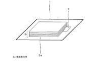
図6は、本発明の実施の形態2に係る真空断熱材100に適用する繊維集合体3bの構成例を示す斜視図である。図6に基づいて、繊維集合体3bの別の構成について説明する。図6に示すように、繊維集合体3bは、繊維を織ることで構成されている。このように、繊維を織物にすることで、繊維の間隔が調整しやすくなり、繊維集合体3bの取り扱いが容易にできるというメリットがある。たとえば、繊維径20μのポリエステル繊維を用い、平織りで製造した繊維集合体3bを、300枚積層して芯材3とし、実施の形態1と同様にして真空断熱材100を得ることができる。なお、積層枚数は、所望する真空断熱材の厚さによって調整すればよい。
FIG. 6 is a perspective view showing a configuration example of a
図7は、繊維集合体3bを適用した真空断熱材100の熱伝導率の測定結果を示す表である。図7に基づいて、繊維集合体3bを積層した芯材3を適用した真空断熱材100の断熱性能評価として行なった熱伝導率の測定結果について説明する。図7には、真空断熱材100の熱伝導率(W/mK)と、比較例として実施の形態1と同様な綿状繊維を芯材に用いた真空断熱材の熱伝導率(W/mK)とを示している。図7の測定結果から、繊維を織ることにより、比較例に比べて断熱性能が改善できることが分かった。
FIG. 7 is a table showing the measurement results of the thermal conductivity of the vacuum
実施の形態3.
図8は、本発明の実施の形態3に係る真空断熱材100に適用する繊維集合体3cを示す平面図である。図8に基づいて、繊維集合体3cについて説明する。図8に示すように、繊維集合体3cは、長繊維不織布で構成されている。このように、長繊維不織布で繊維集合体3cを構成することで、繊維集合体3a及び繊維集合体3bに比べて、生産性が高いというメリットがある。また、繊維集合体3cの端部での繊維の抜けやほつれが少なく、取り扱い性を更に向上することができる。
FIG. 8 is a plan view showing a fiber assembly 3c applied to the vacuum
不織布は、紡糸ノズルから溶出した樹脂を、冷風で冷却した後、繊維中の分子を配向させ、剛性を高めるために延伸装置で延伸してから、コンベア上に補集し、コンベアを任意の速度で動かしながら、ローラーで加圧し巻き取って製造した。なお、真空断熱材内に残存している空気の熱伝導率が0.0001W/mK未満となるように繊維径を10μmとした。また、コンベア上に捕集した不織布は、繊維どうしがばらばらで取り扱い性が悪い場合があり、この場合には加圧時に熱を加え、繊維同士を溶着してもよい。この際、過度の加圧及び加熱溶着は、繊維間の接触面積を増大し、伝熱の増加を招くため、溶着の面積をできるだけ少なくした方がよく、全面積の5%以下に抑えることが望ましい。この方法で、コンベアの速度などの製造条件を調整し、目付けを変えた繊維集合体3cを製造し、300枚積層して実施の形態1と同様にして真空断熱材100を得ることができる。
The non-woven fabric is cooled with cold air after the resin eluted from the spinning nozzle, and then the molecules in the fiber are oriented and stretched with a stretching device to increase the rigidity, and then collected on the conveyor. It was manufactured by pressing and rolling with a roller while moving with. The fiber diameter was set to 10 μm so that the thermal conductivity of air remaining in the vacuum heat insulating material was less than 0.0001 W / mK. Moreover, the nonwoven fabric collected on the conveyor may be disjointed and the handling property may be poor. In this case, heat may be applied during pressurization to weld the fibers together. At this time, excessive pressurization and heat welding increase the contact area between the fibers and increase heat transfer. Therefore, it is better to reduce the area of welding as much as possible, and keep it to 5% or less of the total area. desirable. By this method, the manufacturing conditions such as the speed of the conveyor are adjusted, the fiber aggregate 3c having a different basis weight is manufactured, 300 sheets are stacked, and the vacuum
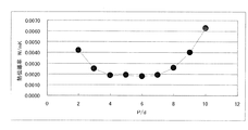
図9は、繊維集合体3cを適用した真空断熱材100の熱伝導率の測定結果を示すグラフである。図9に基づいて、繊維集合体3cを積層した芯材3を適用した真空断熱材100の断熱性能評価として行なった熱伝導率の測定結果について説明する。図9では、横軸が体積目付け(cc/m2 )を、縦軸が熱伝導率(W/mK)を示している。通常、目付けは、1m2 あたりの繊維の重量目付けで表されるが、ここでは比重の異なるその他の材質でも比較できるように1m2 あたりの体積目付けで表している。
FIG. 9 is a graph showing the measurement results of the thermal conductivity of the vacuum
図9に示す測定結果から、14cc/m2 (具体的には13cc/m2 )よりも低い目付けで、綿状の芯材を用いた場合(図4及び図7参照)よりも熱伝導率が小さく、すなわち断熱性能が高くなることが分かった。これは、目付けを低くすることにより繊維集合体3cの厚さが薄くなり、繊維集合体3c中の繊維が厚さ方向に向きにくくなり、断熱方向と直交する方向である面方向により向きやすくできたからであると考えられる。なお、目付けは、低くするほど面方向に向きやすくなると考えられるが、低くしすぎると繊維集合体3cの強度が弱くなり3.5cc/m2 以下では巻き取ることができなかった。 From the measurement results shown in FIG. 9, the thermal conductivity is lower than that when a cotton-like core material is used (see FIGS. 4 and 7) with a basis weight lower than 14 cc / m 2 (specifically, 13 cc / m 2 ). Is small, that is, the heat insulation performance is high. This is because by reducing the basis weight, the thickness of the fiber assembly 3c is reduced, the fibers in the fiber assembly 3c are less likely to be oriented in the thickness direction, and can be more easily oriented in the plane direction that is perpendicular to the heat insulation direction. This is thought to be because of this. In addition, although it is thought that it becomes easy to face to a surface direction, so that fabric weight is made low, when too low, the intensity | strength of the fiber assembly 3c will become weak and it could not wind up at 3.5 cc / m < 2 > or less.
実施の形態4.
本発明の実施の形態4に係る真空断熱材100では、繊維集合体を構成する繊維の断面形状を三角形断面としている。つまり、この実施の形態4では、異形断面の繊維を用いて繊維集合体を製造し、300枚積層して芯材3を得、実施の形態1と同様の方法で真空断熱材100に製造した場合を例に説明する。なお、繊維集合体は、実施の形態2及び実施の形態3などいずれの製造方法で製造してもよいが、ここでは実施の形態3の製造方法で繊維集合体を製造した場合を例に説明する。
In the vacuum
図10は、異形断面の繊維を用いた繊維集合体を適用した真空断熱材100の熱伝導率の測定結果を示す表である。図10に基づいて、異形断面、つまり三角形断面の繊維を用いた繊維集合体を適用した真空断熱材100の断熱性能評価として行なった熱伝導率の測定結果について説明する。なお、図10には、比較例として同等の断面積を有する円形断面の繊維を芯材に用いた真空断熱材の熱伝導率を併せて示している。図10に示す測定結果から、三角形断面を有する繊維を用いた繊維集合体を適用した真空断熱材100では、円形断面を有する繊維を用いた繊維集合体を適用した真空断熱材よりも断熱性能が向上できることが分かった。
FIG. 10 is a table showing the measurement results of the thermal conductivity of the vacuum
真空断熱材100の内部は略真空状態にあるので、芯材3を構成する繊維集合体は外包材1を介して大気圧を受けているが、ある繊維どうしの任意の接点を基準にして見てみると、繊維はその他の接点の両側近傍のその他の繊維との接点を支点とし圧力を受けて撓んでいる。したがって、伝熱性能が向上したのは、繊維断面を三角形としたことにより、同等の断面積を有する円形断面を有する繊維に比べて剛性が向上し、大気圧を受けた時の繊維の撓みが減少したことによると考えられる。このことから、断面形状は三角形に限定されるものではなく、同等の断面積で断面二次モーメントが高くなるような形状であれば、真空断熱材100中で大気圧を受けた時の変形を小さくでき、真空断熱材中の固体の体積分率を低減できるため、断熱性能を向上できるものと考えられる。
Since the inside of the vacuum
実施の形態5.
図11は、本発明の実施の形態5に係る真空断熱材100の繊維集合体を構成する繊維5の形状を示す模式図である。図11に基づいて、真空断熱材100の繊維集合体を構成する繊維5について説明する。その他の芯材の固体伝熱を低減する方法としては、特開2007−285496号公報に開示されているように中空繊維を用いる方法が示されているが、中空繊維は、繊維が長くなるほど真空断熱パネルを製造する際の中空部の排気性が極めて悪くなるため生産性が低いという欠点がある。
FIG. 11 is a schematic diagram showing the shape of the
そこで、実施の形態5では、繊維5の断面形状を略C字型形状とすることにより、芯材3の固体伝熱を低減している。なお、繊維集合体は、実施の形態3の製造方法で製造した場合を例に説明する。図11に示すように、繊維5の断面形状を略C字型形状にすることにより、真空断熱材の真空引き工程における排気性を高める、つまり真空引き性を悪化させないことが可能で、真空パック後には中空繊維と同様に真空断熱材中の固体の体積分率を低減することができるので、断熱性能を向上できる。この繊維集合体を300枚重ねて外包材1へ挿入した後、実施の形態1と同様の方法で真空断熱材100を得ることができる。
Therefore, in
図12は、断面形状が略C字型形状の繊維5を用いて構成された繊維集合体を適用した真空断熱材100の熱伝導率の測定結果を示す表である。図12に基づいて、繊維5を用いて構成された繊維集合体を適用した真空断熱材100の断熱性能評価として行なった熱伝導率の測定結果について説明する。なお、図12には、比較例として円形断面の繊維を芯材に用いた真空断熱材の熱伝導率を併せて示している。ここで、繊維5の外径及び内径とは、真空パック後に略C字型形状の開口部が閉じた状態での外径及び内径を示しているものとする。また、芯材3の密度は、芯材3である繊維集合体の重量を真空断熱材の内容積で除したものである。真空断熱材の内容積は、真空断熱材の外寸法から外包材の厚さを引いてから計算して求めている。
FIG. 12 is a table showing the measurement results of the thermal conductivity of the vacuum
図12に示す測定結果から、繊維5の内径寸法が繊維外径寸法の20乃至70%のものである場合に、真空断熱材100中の芯材3の体積分率を低下させることができ、中実断面の繊維のものである場合よりも断熱性能の向上が確認できた。そして、内径寸法が繊維外径寸法の60乃至70%のものである場合に、もっとも優れた断熱性能を示すことがわかった。数Pa乃至数十Pa程度の真空度で用いる真空断熱材では、断熱性能に与える芯材の固体伝熱の寄与率が大きいので、繊維の内径を大きくするにつれて同一繊維外径における固体の体積分率が減らせる効果がある。
From the measurement results shown in FIG. 12, when the inner diameter dimension of the
これにより、断熱性能が向上していくが、一方で内径が大きくなるにつれ断面二次モーメントが低下するため剛性が低下して、繊維同士の交点を支点とした撓みが増加するとともに、繊維交点での繊維体自体のつぶれが増加することになる。したがって、真空断熱材中の芯材の密度は、内径拡大による固体分減少の計算通りには低下せず、内径寸法が繊維外径の60乃至70%の領域での芯材の密度190kg/m3 を下限として増加へ転じ、断熱性能が悪化したものと考えられる。 As a result, the heat insulation performance is improved, but on the other hand, as the inner diameter is increased, the cross-sectional secondary moment is decreased, so that the rigidity is decreased, and the bending at the intersection of fibers is increased, and at the fiber intersection. The collapse of the fiber body itself will increase. Therefore, the density of the core material in the vacuum heat insulating material does not decrease as calculated for the decrease in the solid content due to the expansion of the inner diameter, and the density of the core material in the region where the inner diameter dimension is 60 to 70% of the fiber outer diameter is 190 kg / m. It is considered that the heat insulation performance deteriorated as the lower limit of 3 was increased.
1 外包材、2 吸着剤、3 芯材、3a 繊維集合体、3b 繊維集合体、3c 繊維集合体、5 繊維、100 真空断熱材。 1 outer packaging material, 2 adsorbent, 3 core material, 3a fiber assembly, 3b fiber assembly, 3c fiber assembly, 5 fibers, 100 vacuum heat insulating material.
Claims (10)
ガスバリア性を有し、前記芯材を収容して内部が真空にされる外包材と、を備えた
ことを特徴とする真空断熱材。 A core material formed by laminating fiber assemblies;
A vacuum heat insulating material, comprising: an outer packaging material that has a gas barrier property and accommodates the core material to be evacuated.
繊維の重なりがないように繊維の方向を一方向に配向して構成された前記繊維集合体を、繊維の方向が略直交するように交互に積層して構成されている
ことを特徴とする請求項1に記載の真空断熱材。 The core material is
The fiber assembly configured by orienting the fibers in one direction so as not to overlap the fibers is configured by alternately laminating the fibers so that the directions of the fibers are substantially orthogonal to each other. Item 2. The vacuum heat insulating material according to Item 1.
ことを特徴とする請求項1に記載の真空断熱材。 The vacuum heat insulating material according to claim 1, wherein the fiber assembly has a woven structure of fibers.
ことを特徴とする請求項1に記載の真空断熱材。 The vacuum heat insulating material according to claim 1, wherein the fiber assembly is a non-woven fabric.
ことを特徴とする請求項4に記載の真空断熱材。 Vacuum heat insulating material according to claim 4, characterized in that it the volume basis weight of the nonwoven fabric and 3.5 cc / m 2 to 13 cc / m 2.
ことを特徴とする請求項1乃至5のいずれかに記載の真空断熱材。 The vacuum heat insulating material according to any one of claims 1 to 5, wherein a cross-sectional shape of the fibers constituting the fiber assembly is substantially triangular.
ことを特徴とする請求項1乃至5のいずれかに記載の真空断熱材。 The vacuum heat insulating material according to any one of claims 1 to 5, wherein a cross-sectional shape of fibers constituting the fiber assembly is substantially C-shaped.
ことを特徴とする請求項7に記載の真空断熱材。 8. The vacuum heat insulating material according to claim 7, wherein an inner diameter dimension of the fiber having the substantially C shape is 20% to 70% of an outer diameter dimension of the fiber.
ことを特徴とする請求項1乃至8のいずれかに記載の真空断熱材。 The vacuum heat insulating material according to any one of claims 1 to 8, wherein an adsorbent placed in a non-woven bag is accommodated in the outer packaging material.
ことを特徴とする断熱箱。 The heat insulation box using the vacuum heat insulating material in any one of the said Claims 1 thru | or 9.
Priority Applications (3)
| Application Number | Priority Date | Filing Date | Title |
|---|---|---|---|
| JP2008078562A JP2009228886A (en) | 2008-03-25 | 2008-03-25 | Vacuum heat insulating material and heat insulating box using the same |
| EP20080254111 EP2105648B1 (en) | 2008-03-25 | 2008-12-22 | Vacuum heat insulating material and heat insulating box using the same |
| CN2009100035989A CN101545572B (en) | 2008-03-25 | 2009-01-20 | Vacuum heat insulating material and heat insulating box using the same |
Applications Claiming Priority (1)
| Application Number | Priority Date | Filing Date | Title |
|---|---|---|---|
| JP2008078562A JP2009228886A (en) | 2008-03-25 | 2008-03-25 | Vacuum heat insulating material and heat insulating box using the same |
Publications (2)
| Publication Number | Publication Date |
|---|---|
| JP2009228886A true JP2009228886A (en) | 2009-10-08 |
| JP2009228886A5 JP2009228886A5 (en) | 2010-07-22 |
Family
ID=40671355
Family Applications (1)
| Application Number | Title | Priority Date | Filing Date |
|---|---|---|---|
| JP2008078562A Pending JP2009228886A (en) | 2008-03-25 | 2008-03-25 | Vacuum heat insulating material and heat insulating box using the same |
Country Status (3)
| Country | Link |
|---|---|
| EP (1) | EP2105648B1 (en) |
| JP (1) | JP2009228886A (en) |
| CN (1) | CN101545572B (en) |
Cited By (2)
| Publication number | Priority date | Publication date | Assignee | Title |
|---|---|---|---|---|
| JP2011174550A (en) * | 2010-02-25 | 2011-09-08 | Hitachi Appliances Inc | Vacuum heat insulation material and equipment using the same |
| KR101330743B1 (en) | 2012-02-17 | 2013-11-18 | 금호석유화학 주식회사 | Core material for vacuum insulator using glass fiber fabric and vacuum insulator using the same |
Families Citing this family (4)
| Publication number | Priority date | Publication date | Assignee | Title |
|---|---|---|---|---|
| JP4789886B2 (en) * | 2007-08-06 | 2011-10-12 | 三菱電機株式会社 | Vacuum insulation and insulation box |
| WO2012164888A1 (en) * | 2011-05-30 | 2012-12-06 | 三菱電機株式会社 | Vacuum heat insulator and heat-insulating box formed using same |
| KR20130015183A (en) * | 2011-08-02 | 2013-02-13 | 삼성전자주식회사 | Vacuum insulation panel with high performance and manufacturing method thereof |
| DE102013016774A1 (en) * | 2013-07-31 | 2015-02-05 | Liebherr-Hausgeräte Lienz Gmbh | Vakuumdämmkörper |
Citations (4)
| Publication number | Priority date | Publication date | Assignee | Title |
|---|---|---|---|---|
| JPH07228218A (en) * | 1994-02-21 | 1995-08-29 | Toray Ind Inc | Webbing for seat belt |
| JP2006017151A (en) * | 2004-06-30 | 2006-01-19 | Fuji Electric Retail Systems Co Ltd | Vacuum heat insulating material |
| JP2006030668A (en) * | 2004-07-16 | 2006-02-02 | Dainippon Printing Co Ltd | Heat insulating shrink label and container with label |
| JP2006194340A (en) * | 2005-01-13 | 2006-07-27 | Toyobo Co Ltd | Heat insulating material, dew proofing cold insulating container and heat insulating container using the same |
Family Cites Families (14)
| Publication number | Priority date | Publication date | Assignee | Title |
|---|---|---|---|---|
| JPH07103955B2 (en) | 1984-04-02 | 1995-11-08 | 株式会社日立製作所 | Vacuum insulation |
| JPH0828776A (en) | 1994-07-19 | 1996-02-02 | Nippon Muki Co Ltd | Core material for vacuum heat insulation material, manufacture thereof and vacuum heat insulation material |
| JP3656028B2 (en) | 2000-12-21 | 2005-06-02 | 松下冷機株式会社 | Vacuum heat insulating material, vacuum heat insulating material, vacuum heat insulating material or recycling method of vacuum heat insulating material |
| WO2002099347A1 (en) * | 2001-06-04 | 2002-12-12 | Matsushita Refrigeration Company | Insulated box body, refrigerator having the box body, and method of recycling materials for insulated box body |
| CN1690500A (en) * | 2004-04-19 | 2005-11-02 | 成都思摩纳米技术有限公司 | Application of vacuum fiber board in thermal insulation |
| JP2005344832A (en) | 2004-06-03 | 2005-12-15 | Matsushita Electric Ind Co Ltd | Vacuum heat insulating material |
| JP2005344870A (en) | 2004-06-04 | 2005-12-15 | Matsushita Electric Ind Co Ltd | Vacuum heat insulating material, and refrigerator having the same |
| JP2006283817A (en) | 2005-03-31 | 2006-10-19 | Kurabo Ind Ltd | Vacuum heat insulation material |
| JP4523870B2 (en) | 2005-04-27 | 2010-08-11 | 日本トムソン株式会社 | Linear motion guidance unit |
| JP4215745B2 (en) * | 2005-05-20 | 2009-01-28 | 日立アプライアンス株式会社 | Vacuum heat insulating material, refrigerator using vacuum heat insulating material, and manufacturing method of vacuum heat insulating material |
| CN102734601B (en) * | 2005-05-23 | 2014-11-26 | 松下电器产业株式会社 | Vacuum heat insulating material |
| JP4580843B2 (en) * | 2005-08-24 | 2010-11-17 | 日立アプライアンス株式会社 | Vacuum heat insulating material and refrigerator using the same |
| EP2484951B1 (en) * | 2005-10-18 | 2018-01-31 | LG Electronics Inc. | Vacuum insulation panel and insulation structure of refrigerator applying the same |
| JP4814684B2 (en) | 2006-04-20 | 2011-11-16 | 日立アプライアンス株式会社 | Vacuum heat insulating material, refrigerator and vehicle using the same |
-
2008
- 2008-03-25 JP JP2008078562A patent/JP2009228886A/en active Pending
- 2008-12-22 EP EP20080254111 patent/EP2105648B1/en not_active Not-in-force
-
2009
- 2009-01-20 CN CN2009100035989A patent/CN101545572B/en not_active Expired - Fee Related
Patent Citations (4)
| Publication number | Priority date | Publication date | Assignee | Title |
|---|---|---|---|---|
| JPH07228218A (en) * | 1994-02-21 | 1995-08-29 | Toray Ind Inc | Webbing for seat belt |
| JP2006017151A (en) * | 2004-06-30 | 2006-01-19 | Fuji Electric Retail Systems Co Ltd | Vacuum heat insulating material |
| JP2006030668A (en) * | 2004-07-16 | 2006-02-02 | Dainippon Printing Co Ltd | Heat insulating shrink label and container with label |
| JP2006194340A (en) * | 2005-01-13 | 2006-07-27 | Toyobo Co Ltd | Heat insulating material, dew proofing cold insulating container and heat insulating container using the same |
Cited By (2)
| Publication number | Priority date | Publication date | Assignee | Title |
|---|---|---|---|---|
| JP2011174550A (en) * | 2010-02-25 | 2011-09-08 | Hitachi Appliances Inc | Vacuum heat insulation material and equipment using the same |
| KR101330743B1 (en) | 2012-02-17 | 2013-11-18 | 금호석유화학 주식회사 | Core material for vacuum insulator using glass fiber fabric and vacuum insulator using the same |
Also Published As
| Publication number | Publication date |
|---|---|
| EP2105648B1 (en) | 2014-04-16 |
| EP2105648A1 (en) | 2009-09-30 |
| CN101545572B (en) | 2011-08-24 |
| CN101545572A (en) | 2009-09-30 |
Similar Documents
| Publication | Publication Date | Title |
|---|---|---|
| KR101164306B1 (en) | Vacuum heat insulating material, heat-insulating box body using the same and refrigerator | |
| JP4789886B2 (en) | Vacuum insulation and insulation box | |
| WO2010087039A1 (en) | Vacuum insulation material and insulation box using the same | |
| KR20090017645A (en) | Vacuum heat insulation material | |
| JP2009228886A (en) | Vacuum heat insulating material and heat insulating box using the same | |
| JP2008223922A (en) | Vacuum heat insulating material | |
| JP2011074934A (en) | Vacuum thermal insulator and thermally insulating box including the vacuum thermal insulator | |
| JP5111331B2 (en) | Vacuum heat insulating material and heat insulating box using this vacuum heat insulating material | |
| WO2017195329A1 (en) | Vacuum heat-insulating material and manufacturing method therefor | |
| JP4969436B2 (en) | Vacuum insulation material and equipment using the same | |
| JP2012047211A (en) | Vacuum heat insulating material and refrigerator using the same | |
| JP2012092870A (en) | Vacuum heat insulating material and heat insulating box using the same | |
| JP2011038574A (en) | Vacuum heat insulating material and refrigerator using this | |
| JP4997198B2 (en) | Vacuum heat insulating material, heat insulating box using the same, and refrigerator | |
| JP2010127421A (en) | Vacuum thermal-insulating material and thermal insulation box | |
| JP2010007806A (en) | Vacuum thermal insulation panel and thermal insulation box body with this | |
| JP6793571B2 (en) | Vacuum heat insulating material, equipment equipped with it, and manufacturing method of vacuum heat insulating material | |
| JP2013036595A (en) | Vacuum heat insulating material | |
| JP4969555B2 (en) | Vacuum insulation and insulation box | |
| EP2985376B1 (en) | Core material for vacuum insulator, comprising organic synthetic fiber, and vacuum insulator containing same | |
| JP2005273696A (en) | Vacuum heat insulating material, heat-retaining and cold-keeping apparatus equipped with vacuum insulating material, and heat insulating board | |
| KR102217150B1 (en) | Vacuum Insulation Material | |
| JP6184841B2 (en) | Vacuum insulation material and equipment using the same | |
| JP2010139006A (en) | Vacuum heat insulating material | |
| CN115771318A (en) | Vacuum heat insulating material and method for producing same |
Legal Events
| Date | Code | Title | Description |
|---|---|---|---|
| A521 | Written amendment |
Free format text: JAPANESE INTERMEDIATE CODE: A523 Effective date: 20100604 |
|
| A621 | Written request for application examination |
Free format text: JAPANESE INTERMEDIATE CODE: A621 Effective date: 20100604 |
|
| A977 | Report on retrieval |
Free format text: JAPANESE INTERMEDIATE CODE: A971007 Effective date: 20120214 |
|
| A131 | Notification of reasons for refusal |
Free format text: JAPANESE INTERMEDIATE CODE: A131 Effective date: 20120221 |
|
| A131 | Notification of reasons for refusal |
Free format text: JAPANESE INTERMEDIATE CODE: A131 Effective date: 20120703 |
|
| A521 | Written amendment |
Free format text: JAPANESE INTERMEDIATE CODE: A523 Effective date: 20120828 |
|
| A02 | Decision of refusal |
Free format text: JAPANESE INTERMEDIATE CODE: A02 Effective date: 20130305 |