JP4580843B2 - Vacuum heat insulating material and refrigerator using the same - Google Patents
Vacuum heat insulating material and refrigerator using the same Download PDFInfo
- Publication number
- JP4580843B2 JP4580843B2 JP2005242277A JP2005242277A JP4580843B2 JP 4580843 B2 JP4580843 B2 JP 4580843B2 JP 2005242277 A JP2005242277 A JP 2005242277A JP 2005242277 A JP2005242277 A JP 2005242277A JP 4580843 B2 JP4580843 B2 JP 4580843B2
- Authority
- JP
- Japan
- Prior art keywords
- heat insulating
- insulating material
- vacuum heat
- core material
- vacuum
- Prior art date
- Legal status (The legal status is an assumption and is not a legal conclusion. Google has not performed a legal analysis and makes no representation as to the accuracy of the status listed.)
- Expired - Fee Related
Links
Images


Landscapes
- Thermal Insulation (AREA)
- Refrigerator Housings (AREA)
- Laminated Bodies (AREA)
Description
本発明は、真空断熱材及びそれを用いた冷蔵庫に関する。 The present invention relates to a vacuum heat insulating material and a refrigerator using the same.
(従来技術1)
従来の真空断熱材としては、特開2001−336691号公報(特許文献1)に示されたものがある。この特許文献1に記載の真空断熱材は、平均直径が1μm以上5μm以下の無機繊維からなるシート状成形体を少なくとも2層以上積層してなる芯材を、ガスバリア性フィルムで覆い、その内部を減圧し、密封したものであって、圧縮成型により、前記真空断熱材の厚み方向に垂直な側面部に少なくとも一本以上の溝を形成して、該真空断熱材の折り曲げを可能にしたものである。
(従来技術2)
また、従来の真空断熱材としては、特開2004−197954号公報(特許文献2)に示されたものがある。この特許文献2に記載の真空断熱材は、熱溶着層を有するガスバリア性の外被材と板状の芯材とを有し、芯材の周囲に芯材を間に含まず密着した外被材のみから構成される周辺部が形成された真空断熱材であって、真空断熱材の厚みが0.5mm以上5mm以下として、周縁部を芯材形状に合わせることによって、容易に任意形状の真空断熱材を作製できるようにするものである。
(従来技術3)
また、従来の真空断熱材としては、特開2002−81596号公報(特許文献3)に示されたものがある。特許文献3に記載の真空断熱材は、繊維径分布のピーク値が1μm以下0.1μm以上である無機繊維芯材と、ガスバリア性を有する外皮材とからなる真空断熱材であって、前記芯材がSiO2を主成分とし、かつ繊維材料を固形化するための結合材を含まない構成としたことにより、真空断熱材としての可撓性を有するようにしていた。
(Prior art 1)
As a conventional vacuum heat insulating material, there exists a thing shown by Unexamined-Japanese-Patent No. 2001-336691 (patent document 1). In the vacuum heat insulating material described in
(Prior art 2)
Moreover, as a conventional vacuum heat insulating material, there exist some which were shown by Unexamined-Japanese-Patent No. 2004-197954 (patent document 2). The vacuum heat insulating material described in Patent Document 2 has a gas barrier outer cover material having a heat-welded layer and a plate-shaped core material, and the outer cover is closely attached without surrounding the core material. A vacuum heat insulating material in which a peripheral portion composed only of a material is formed, and the vacuum heat insulating material has a thickness of 0.5 mm or more and 5 mm or less, and the peripheral portion is matched to the shape of the core material to easily form a vacuum of any shape. This makes it possible to produce a heat insulating material.
(Prior art 3)
Moreover, as a conventional vacuum heat insulating material, there exists a thing shown by Unexamined-Japanese-Patent No. 2002-81596 (patent document 3). The vacuum heat insulating material described in Patent Document 3 is a vacuum heat insulating material comprising an inorganic fiber core material having a fiber diameter distribution peak value of 1 μm or less and 0.1 μm or more, and an outer skin material having gas barrier properties. Since the material is composed of SiO2 as a main component and does not include a binder for solidifying the fiber material, the material has flexibility as a vacuum heat insulating material.
近年、地球温暖化に対する観点から、家電品の消費電力量削減の必要性が望まれている。そして、冷蔵庫は家電品の中で特に消費電力量の多い製品であるため、冷蔵庫の断熱箱体中に真空断熱材を採用して、この断熱箱体の熱漏洩量を低減することが提案されている。この真空断熱材の応用展開を推進するためには、コストアップや断熱性能の低下を招くことなく、被取付け部の形状に沿って真空断熱材を配設できるように変形性及び形状保持性を付与することが重要な課題となっている。 In recent years, from the viewpoint of global warming, the necessity of reducing the power consumption of home appliances is desired. And since the refrigerator is a product that consumes a lot of electric power among household electrical appliances, it is proposed to reduce the amount of heat leakage of the heat insulating box by adopting a vacuum heat insulating material in the heat insulating box of the refrigerator. ing. In order to promote the application development of this vacuum heat insulating material, the deformability and shape retainability should be improved so that the vacuum heat insulating material can be arranged along the shape of the mounted part without incurring cost increase or deterioration of heat insulating performance. Granting has become an important issue.
しかしながら、特許文献1の真空断熱材(従来技術1)では、圧縮成型により真空断熱材に厚み方向に垂直な側面部に溝を形成し、厚さ方向に薄くなった溝部で真空断熱材を折り曲げるようにするものであるので、真空断熱材としての厚さが溝部で薄くなり、この溝部での断熱性能が低下してしまう、という問題があった。そして、特許文献1には、真空断熱材を被取付け部の形状に沿って変形させた場合における真空断熱材の形状保持性に関しては開示されていない。
However, in the vacuum heat insulating material (prior art 1) of
また、特許文献2の真空断熱材(従来技術2)では、芯材と熱溶着部の間には芯材を間に含まない外被材のみから構成される部分が残るため、その部分での断熱性能が低下してしまう、という問題があった。そして、特許文献2には、真空断熱材を被取付け部の形状に沿って変形させた場合における真空断熱材の形状保持性に関しては開示されていない。 Moreover, in the vacuum heat insulating material (prior art 2) of patent document 2, since the part comprised only from the jacket material which does not contain a core material remains between a core material and a heat welding part, in the part There was a problem that the heat insulation performance deteriorated. Patent Document 2 does not disclose the shape retention of the vacuum heat insulating material when the vacuum heat insulating material is deformed along the shape of the attached portion.
また、特許文献3の真空断熱材(従来技術3)では、被取付け部の形状に沿って真空断熱材を変形させた場合に、真空断熱材が元に戻ろうとする力(スプリングバック力)により、被取付け部の取付け面から離れてしまう、という問題があった。なお、特許文献3の真空断熱材では、繊維径分布のピーク値が1μm以下0.1μm以上の超極細無機繊維を用いるため、単品でも生産性が低く高価であると共に、繊維集合体を重ねて厚みを稼ぐ必要があり、真空断熱材のコストアップを招いていた。 Moreover, in the vacuum heat insulating material (prior art 3) of patent document 3, when a vacuum heat insulating material is deformed along the shape of a to-be-attached part, by the force (spring back force) which a vacuum heat insulating material tries to return to the original. There was a problem that it was separated from the mounting surface of the mounted portion. In addition, in the vacuum heat insulating material of patent document 3, since the ultrafine inorganic fiber having a peak value of the fiber diameter distribution of 1 μm or less and 0.1 μm or more is used, even a single product is low in productivity and expensive, and the fiber aggregate is overlapped. It was necessary to increase the thickness, leading to an increase in the cost of the vacuum heat insulating material.
本発明の目的は、断熱性能を確保しつつ、被取付け部に沿って変形された形状を保持できる真空断熱材及びそれを用いた冷蔵庫を提供することにある。 The objective of this invention is providing the vacuum heat insulating material which can hold | maintain the shape deform | transformed along the to-be-attached part, ensuring a heat insulation performance, and a refrigerator using the same.
前述の目的を達成するための本発明の第1の態様は、ガスバリア性を有する外被材中に芯材を真空封止した真空断熱材であって、前記芯材は結合剤を含まない無機もしくは有機の繊維重合体で形成すると共に、前記外被材内に前記芯材と共に変形可能で且つ曲げ荷重を加えて曲げたときの圧縮応力或いは引っ張り応力により前記芯材とずれを生じさせ変形後の前記曲げ荷重が解除された該芯材形状を保持可能な変形保持部材が配置されたものである。 A first aspect of the present invention for achieving the above object is a vacuum heat insulating material obtained by vacuum-sealing a core material in a jacket material having a gas barrier property, wherein the core material does not contain a binder. Alternatively, it is formed of an organic fiber polymer, and can be deformed together with the core material in the jacket material, and after being deformed by causing a deviation from the core material due to a compressive stress or a tensile stress when bent by applying a bending load. The deformation holding member capable of holding the core material shape released from the bending load is disposed.
係る本発明の第1の態様におけるより好ましい具体的構成例は次の通りである。
(1)前記芯材を板状の有機の繊維重合体で形成し、前記変形保持部材をフィルム状に形成して前記芯材の内部に設置したこと。
(2)前記芯材を複数層の繊維重合体で形成し、前記変形保持部材を前記繊維重合体の層間に介在させたこと。
(3)前記フィルム状の変形保持部材の大きさを前記芯材の大きさより小さくしたこと。
(4)真空断熱材が平面形状の状態から曲面半径10mm以上の被取付け部の曲げ部に設置可能な曲げた形状の状態とされたものであること。
(5)熱遮蔽性を有するアルミニウムで前記フィルム状の変形保持部材を形成したこと。
(6)前記芯材を脱気圧縮して前記変形保持部材と共に内袋の内部に収納し、この内袋を収納した前記外被材における内袋内を含む内部を減圧し密封してなること。
A more preferable specific configuration example in the first aspect of the present invention is as follows.
(1) The core material is formed of a plate-like organic fiber polymer, and the deformation holding member is formed in a film shape and installed inside the core material.
(2) The core material is formed of a plurality of layers of fiber polymers, and the deformation holding member is interposed between the layers of the fiber polymers.
(3) The size of the film-shaped deformation holding member is made smaller than the size of the core material.
(4) The vacuum heat insulating material is in a bent shape that can be installed in a bent portion of a mounted portion having a curved surface radius of 10 mm or more from a flat shape .
(5) The film-shaped deformation holding member is formed of aluminum having heat shielding properties.
(6) The core material is degassed and compressed, and stored in the inner bag together with the deformation holding member, and the inside including the inner bag in the outer jacket material storing the inner bag is decompressed and sealed. .
また、本発明の第2の態様は、ガスバリア性を有する外被材中に芯材を真空封止した真空断熱材を外箱と内箱とによって形成される空間に配設すると共に、その真空断熱材の周囲の前記空間に発泡断熱材を充填してなる冷蔵庫において、前記芯材は結合剤を含まない無機もしくは有機の繊維重合体で形成すると共に、前記外被材内に前記芯材と共に変形し且つ曲げ荷重を加えて曲げたときの圧縮応力或いは引っ張り応力により該芯材とずれを生じさせ変形後の前記曲げ荷重が解除された該芯材形状を保持する変形保持部材を配置して前記真空断熱材を構成し、前記真空断熱材を前記外箱または前記内箱の変形部に沿って変形して配置したものである。 Further, according to the second aspect of the present invention, a vacuum heat insulating material obtained by vacuum-sealing a core material in a jacket material having gas barrier properties is disposed in a space formed by an outer box and an inner box, and the vacuum In the refrigerator in which the space around the heat insulating material is filled with the foam heat insulating material, the core material is formed of an inorganic or organic fiber polymer not containing a binder, and the core material is combined with the core material. by placing a compressive stress or tensile deformation holding member for holding the bending core material shaped load is released after deformation is produced core material and displaced by stress when bent by adding the deformed and bending load The vacuum heat insulating material is configured, and the vacuum heat insulating material is deformed and arranged along the deformed portion of the outer box or the inner box.
係る本発明の第2の態様におけるより好ましい具体的構成例は次の通りである。
(1)前記外箱または前記内箱の2つの面が交差する角部に前記真空断熱材を折り曲げて設置したこと。
(2)前記内箱の角部の曲面半径の大きさが10mm以上であること。
(3)前記内箱の角部に沿うように折り曲げて設置した真空断熱材の端部と、前記外箱の平坦面を延びる真空断熱材の端部とを投影面で重合させたこと。
A more preferable specific configuration example in the second aspect of the present invention is as follows.
(1) The vacuum heat insulating material is bent and installed at a corner where two surfaces of the outer box or the inner box intersect.
(2) The magnitude | size of the curved-surface radius of the corner | angular part of the said inner box is 10 mm or more.
(3) The end of the vacuum heat insulating material that is bent and installed along the corner of the inner box and the end of the vacuum heat insulating material that extends the flat surface of the outer box are superposed on the projection surface.
本発明によれば、断熱性能を確保しつつ、被取付け部に沿って変形された形状を保持できる真空断熱材及びそれを用いた冷蔵庫を提供することができる。 ADVANTAGE OF THE INVENTION According to this invention, the vacuum heat insulating material which can hold | maintain the shape deform | transformed along the to-be-attached part, ensuring a heat insulation performance, and a refrigerator using the same can be provided.
以下、本発明の複数の実施形態について図を用いて説明する。各実施形態の図における同一符号は同一物または相当物を示す。なお、本発明は、それぞれの実施形態を必要に応じて適宜に組み合わせることにより、さらに効果的なものとすることを含むものである。
(第1実施形態)
本発明の第1実施形態の真空断熱材及びそれを用いた冷蔵庫を図1から図5を用いて説明する。
Hereinafter, a plurality of embodiments of the present invention will be described with reference to the drawings. The same reference numerals in the drawings of the respective embodiments indicate the same or equivalent. In addition, this invention includes making it more effective by combining each embodiment suitably as needed.
(First embodiment)
The vacuum heat insulating material of 1st Embodiment of this invention and the refrigerator using the same are demonstrated using FIGS. 1-5.
まず、本実施形態の冷蔵庫の全体に関して図1を参照しながら説明する。図1は本発明の第1実施形態の真空断熱材及びそれを用いた冷蔵庫を示す縦断面図である。 First, the whole refrigerator of this embodiment is demonstrated, referring FIG. FIG. 1 is a longitudinal sectional view showing a vacuum heat insulating material according to a first embodiment of the present invention and a refrigerator using the same.
冷蔵庫は、箱状に形成された冷蔵庫の箱体20と、冷蔵庫の箱体20の前面開口を開閉する扉6とを備えて構成されている。冷蔵庫の箱体20は、外箱23と、内箱21と、外箱23と内箱21とによって形成される断熱壁中に設置された後述する真空断熱材30,80と、前記外箱23や内箱21および前記真空断熱材30,80と接着可能な、それ自身に接着力を有するウレタン等の発泡断熱材22とにより構成されている。この断熱壁は、底壁、両側壁、上壁及び背壁から構成されている。最下部の扉6は、外箱と、内箱と、外箱と内箱とによって形成される断熱壁中に設置された後述する真空断熱材80と、外箱や内箱および前記真空断熱材80と接着可能な、それ自身に接着力を有するウレタン等の発泡断熱材とにより構成されている。上部の扉6に真空断熱材80を設置しても良い。
The refrigerator includes a
また、冷蔵庫の箱体20は、温度の異なる貯蔵室10〜12を複数形成しており、各貯蔵室10〜12間には区画壁(図示せず)が設けられている。貯蔵室10は、温度の低い貯蔵室(具体的には冷凍室)であり、複数の貯蔵室における最下部に配置されている。貯蔵室11は、温度の低い貯蔵室10より温度が高い貯蔵室(具体的には野菜室)であり、複数の貯蔵室における中間部に配置されている。貯蔵室12は、温度の低い貯蔵室10より温度が高い貯蔵室(具体的には冷蔵室)であり、複数の貯蔵室における最上部に配置されている。貯蔵室10〜12は、圧縮機13、凝縮器14、減圧装置及び冷却器などからなる冷凍サイクル及び冷却ファンなどを用いて冷却される。
Moreover, the
内箱21は、貯蔵室10〜12を形成する壁面を構成するものであり、底面、両側面、上面及び背面からなっている。外箱23は、冷蔵庫の箱体20の外観を形成する壁面を構成するものであり、底面、両側面、上面及び背面からなっている。なお、冷蔵庫の箱体20の底壁の背面側には、圧縮機を収納する機械室を形成するための段部を有しており、内箱21及び外箱23の底面はこれに伴う段部を有している。
The
真空断熱材30は、断熱壁の曲げ部24に沿って配設した真空断熱材であり、曲げ部24の内箱21側に設置する場合は、内箱21の形状に沿って内箱21に密着するように設置してある。また、真空断熱材30は、曲げ部24の外箱23側に設置する場合は、外箱23の形状に沿って設置してある。
The vacuum
前記断熱壁の曲げ部24は断熱壁の変形部を構成する部分である。そして、断熱壁の変形部は、内箱21または外箱23における二つの面が交差する角部である曲げ部24の他に、内箱21または外箱23における凹凸部などである変形部が含まれる。
The
真空断熱材80は、断熱壁の平面部に配設した真空断熱材であり、図3にて後述するように、真空断熱材30を折り曲げることをしないで、平面形状のままで、断熱壁内に配設した真空断熱材である。外箱23の一面(背面)に沿って設置された真空断熱材80の端部は、内箱21の一面(上面)から曲げ部24を経て他の面(背面)に沿って延びる真空断熱材30の端部と投影面で重合している。係る構成によって、発泡断熱材22の充填性を確保しつつ、真空断熱材80、30の設置面積を増大することができ、断熱性能を向上することができる。
The vacuum
次に、本実施形態における曲げ部24への真空断熱材の設置例を図2により説明する。図2は図1のC部を拡大した断面図である。図2では真空断熱材30の理解を容易にするため、真空断熱材30を図1より強調して示してある。
Next, an installation example of the vacuum heat insulating material on the bending
図2において、真空断熱材30は断熱壁の曲げ部24の内箱面21aの形状に沿って該内箱面21aに密着するように配設された真空断熱材であり、ガスバリア性を有する外被材31中に、結合剤を含まない無機繊維重合体もしくは有機繊維重合体にて形成された芯材を32及びガスを吸着するゲッタ剤と共に収納し、所定の真空度にて真空封止して構成してある。無機繊維重合体もしくは有機繊維重合体は、平均繊維径3μmから5μmの汎用性の高いものが用いられており、従来技術3の真空断熱材に用いられる繊維径分布のピーク値が1μm以下、0.1μm以上の超極細無機繊維と比較して安価なものとすることができる。
In FIG. 2, a vacuum
真空断熱材30は、その製造時は、真空断熱材30自身の生産性の向上が図れるように、図3にて後述するように略平面形状として製造される。そして、略平面形状として製造された真空断熱材30を冷蔵庫の箱体20に組み込む際には、前述したように、曲げ部24の内箱面21aの形状に沿って密着するように、真空断熱材30を曲げた状態で設置する。
The vacuum
従って、本実施形態においては、略平面形状として製造された真空断熱材を、図2に示すように、所定の曲面半径R1で、所定の角度Θ1に曲げられるように、且つ、曲げた形状を保持できるように、無機繊維重合体もしくは有機繊維重合体にて形成された芯材32中に、例えば、アルミニウム等の金属製或いは、ポリエチレンテレフタレート樹脂やポリアミド樹脂等の合成樹脂製の変形保持部材であるフィルム33を介在させてある。
Therefore, in this embodiment, the vacuum heat insulating material manufactured as a substantially planar shape is bent at a predetermined curved surface radius R1 and at a predetermined angle Θ1 as shown in FIG. In the
変形保持部材であるフィルム33を心材32内に有する構成としたことによって、このフィルム33が、いわば骨材として機能し、真空断熱材30の形状が保持される。
By having the structure which has the
フィルム33を芯材32中に介在させる方式例としては、図2に示すように、所定の厚さt1寸法を有する芯材32中に、該t1寸法より厚さの小さいt2寸法若しくはt3寸法の複数の層32a、32bを作り、該複数の層32aと32bとの間に、フィルム33を設置することにより、真空断熱材30を所定の曲面半径R1で、所定の角度Θ1に曲げても、芯材32の層32a、32bを構成する無機繊維重合体もしくは有機繊維重合体が破壊する程度が少なく、且つ、該無機繊維重合体もしくは有機繊維重合体による外被材31の損傷が少なくなるように構成されている。
As an example of a method of interposing the
つまり、図2において、前述したフィルム33を設置しない場合は、厚さt1寸法を有する芯材32を曲げた場合、その内面半径R1と、外面半径R3とが成す曲面の長さL1寸法(L1=2π×R1×Θ1/360)と、L3寸法(L3=2π×(R1+t1)×Θ1/360)との差ΔL3寸法(ΔL3=L3−L1)分が、その内面半径R1の部分において強制的に圧縮されるか、或いは、その外面半径R3の部分において強制的に引っ張り力を受けるので、芯材32を形成する無機繊維重合体もしくは有機繊維重合体が有る程度の割合で破壊してしまう恐れがある。
That is, in FIG. 2, when the
そこで、本実施形態においては、所定の厚さt1寸法を有する芯材32が、該t1寸法より厚さの小さいt2寸法若しくはt3寸法の複数の層32aと32bとに、フィルム33により分離されているので、芯材32を曲げた場合には、前記複数の層32a或いは32bがそれぞれ単独に曲がるので、層32aにおいては、その内面半径R1と、外面半径R2とが成す曲面の長さL1寸法(L1=2π×R1×Θ1/360)と、L2寸法(L2=2π×(R1+t2)×Θ1/360)との差ΔL1寸法(ΔL1=L2−L1)分が、前述したΔL3寸法より小さく成り、また、層32bにおいては、その内面半径R2と外面半径R3とが成す曲面の長さL2寸法(L2=2π×R2×Θ1/360)と、L3寸法(L3=2π×(R2+t3)×Θ1/360)との差ΔL2寸法(ΔL2=L3−L2)分が、前述したΔL3寸法より小さく成る。これによって、夫々の内面半径R1の部分或いは外面半径R2の部分において強制的に圧縮される圧縮量が、前述したΔL3寸法時より小さくなるので、或いは、その内面半径R2の部分或いは外面半径R3の部分において強制的に引っ張られる量が、前述したΔL3寸法時より少なくなるので、層32aや層32bを形成する無機繊維重合体もしくは有機繊維重合体が破壊する程度が少なくなり、該無機繊維重合体もしくは有機繊維重合体による外被材31の損傷が少なくなるように構成されている。
Therefore, in the present embodiment, the
また、芯材32の厚さt1寸法より厚さの小さい層32aと32bとを形成し、該層間に、これらの層を形成する無機繊維重合体もしくは有機繊維重合体との間で、曲げたときの圧縮応力或いは引っ張り応力により、ずれを生じることのできるフィルム状部材、例えば、アルミニウム等の金属製或いはポリエチレンテレフタレート樹脂やポリアミド樹脂等の合成樹脂製のフィルム33を介在させることにより、前述した所定の曲面半径R1で、所定の角度Θ1に曲げるときに、芯材32の層32a、32bと、フィルム33とが互いにずれることにより、所定の曲げ荷重に対する、芯材32の弾性変形量が大きくなるように構成されている。
Further, the
なお、フィルム33と層32a或いは32bとのずれを抑制しないためには、図2に示す曲面部R1、R2、R3より、フィルム33のはみ出す寸法L4、L5を零より大きく設定する事が望ましい。
In order not to suppress the deviation between the
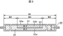
次に、曲げる前の真空断熱材30を図3により説明する。図3は図2の真空断熱材30の曲げる前の状態を示す断面図である。
Next, the vacuum
図3において、真空断熱材30は、真空断熱材30自身の生産性の向上を図れるように、所定の面30aを略平面形状として製造される。図中のW3寸法は、前述したフィルム33の大きさを示すものであり、該フィルム33の大きさ寸法W3を、芯材32の大きさ寸法W1より小さくすることにより、フィルム33と外被材31との間にヒートブリッジが生じ難いように構成してある。つまり、真空断熱材30の外被材31は、ガスバリア性を向上するために、通常はアルミニウム等の金属箔或いは金属蒸着層を中間層として、その表裏に合成樹脂等のフィルムをラミネートした複合ラミネートフィルムを使用してあるので、外被材31とフィルム33との離間距離が小さいと、金属箔或いは金属蒸着層の熱伝導性により該部でヒートブリッジが生じる恐れがある。従って、本実施形態においては、前記フィルム33と前記外被材31との間に、前記ヒートブリッジが生じ難い寸法W2、W4を形成するように構成してある。
In FIG. 3, the vacuum
なお、フィルム33に、熱反射性を有するアルミニウム等の金属フィルムを使用する場合は、フィルム33の大きさ寸法W3が大きいほど熱反射効果が大きいので、その場合は、上記W2、W4寸法を確保しつつ、W3寸法を出来るだけ大きく設定することが望ましい。
When a metal film such as aluminum having heat reflectivity is used for the
次に、真空断熱材の変形量と曲げ荷重との関係について図4により説明する。図4は本実施形態及び比較例の真空断熱材の曲げ特性説明図であり、例えば、前述した図3の略平面形状を成す真空断熱材を、図2に示したように曲げた場合における特性説明図である。図4において、縦軸は真空断熱材を曲げるために付加する曲げ荷重を示し、横軸はその変形量を、例えば、図2にて前述したΔL3寸法(図2の内面半径R1と外面半径R3とが成す曲面の長さの差)相当を示す。 Next, the relationship between the amount of deformation of the vacuum heat insulating material and the bending load will be described with reference to FIG. FIG. 4 is an explanatory view of bending characteristics of the vacuum heat insulating materials of the present embodiment and the comparative example. For example, the characteristics when the vacuum heat insulating material having the substantially planar shape of FIG. 3 described above is bent as shown in FIG. It is explanatory drawing. In FIG. 4, the vertical axis represents the bending load applied to bend the vacuum heat insulating material, and the horizontal axis represents the amount of deformation, for example, the ΔL3 dimension described above with reference to FIG. 2 (inner radius R1 and outer radius R3 in FIG. 2). Difference in the length of the curved surface formed by
図4中の点線にて示す曲線Aはフィルムを有しない比較例の真空断熱材を曲げた場合の特性であり、初期荷重下においては、曲げ荷重と変形量がほぼ比例する比例曲線A1を描き、ある荷重N2を超えると、芯材を形成する無機繊維重合体もしくは有機繊維重合体の一部に破壊が生じて変形量が急増する曲線A2を描く。そして、それ以上の曲げ荷重を加えると、繊維がほとんど破壊するため、微荷重の増加により変形量が増大する曲線A3を描く。 A curve A shown by a dotted line in FIG. 4 is a characteristic when the vacuum heat insulating material of the comparative example having no film is bent. Under an initial load, a proportional curve A1 in which the bending load and the deformation amount are approximately proportional is drawn. When a certain load N2 is exceeded, a curve A2 is drawn in which a part of the inorganic fiber polymer or organic fiber polymer that forms the core material breaks down and the amount of deformation rapidly increases. When a bending load of more than that is applied, the fiber is almost broken, so that a curve A3 in which the amount of deformation increases due to an increase in the fine load is drawn.
一方、図4中の実線にて示す曲線Bは本実施形態の真空断熱材30を曲げた場合の特性であり、例えば、図2にて前述したように、芯材32中に複数の層を形成し、該層間に前述したフィルム33を介在させた場合である。図4に示すように、初期荷重下においては、曲げ荷重と変形量がほぼ比例する比例曲線B1を描くが、その勾配は前述した曲線A1よりなだらかに成る。つまり、所定の曲げ荷重に対する変形量が大きく成る。これは、前述したフィルム33により、芯材の厚さが、芯材の厚さより薄い複数層に分割された効果であり、その変形量(δ2)は、発明者らの実験によれば、従来の変形量(δ1)より約2割程度増加した。
On the other hand, a curve B shown by a solid line in FIG. 4 is a characteristic when the vacuum
なお、本実施形態の真空断熱材30においても、曲げ荷重を増加して、ある荷重N1を超えると、芯材32を形成する無機繊維重合体もしくは有機繊維重合体の一部に破壊が生じて変形量が急増する曲線B2を描く。そして、それ以上の曲げ荷重を加えると、繊維がほとんど破壊するため、微荷重の増加により変形量が増大する曲線B3を描く。このように、芯材32を形成する無機繊維重合体もしくは有機繊維重合体に破壊が生じると、該繊維が形成していた真空空間も破壊されて、繊維同士の接触が増加するので、断熱性能の低下を招く恐れがあるのは、従来の真空断熱材と同様である。
In addition, also in the vacuum
従って、本実施形態においては、図2にて説明したΔL1寸法(ΔL1=L2−L1)やΔL2寸法(ΔL2=L3−L2)を上記した変形量(δ2)以下に設定するのが望ましい。 Therefore, in the present embodiment, it is desirable to set the ΔL1 dimension (ΔL1 = L2-L1) and the ΔL2 dimension (ΔL2 = L3-L2) described in FIG. 2 to be equal to or less than the above-described deformation amount (δ2).
上述した実施形態によれば、ガスバリア性を有する外被材31中に、芯材32を真空封止した真空断熱材30を曲げ部24に沿って配設し、芯材32を無機繊維重合体もしくは有機繊維重合体にて形成し、フィルム33を芯材32の厚みの中で、しかも、曲げ部24に対向するように介在させたので、真空断熱材30を曲げるときに、所定の曲げ荷重に対する、芯材32の弾性変形量が大きくなり、且つ、芯材32を構成する無機繊維重合体もしくは有機繊維重合体が破壊する程度が少ないので、該無機繊維重合体もしくは有機繊維重合体による外被材31の損傷が少なくなり、優れた断熱性能を保持したまま、形状折り曲げ性を有する真空断熱材30を提供できる。なお、真空断熱材30を曲げたときに、該曲げ部の、芯材32とフィルム33とが互いにずれるようになるので、曲げた状態を保持する形状保持性を有する真空断熱材30を提供できる。
According to the above-described embodiment, the vacuum
また、芯材32を複数層32a、32bの無機繊維重合体もしくは有機繊維重合体にて構成し、その層間にフィルム33を介在させたので、真空断熱材30を曲げるときに、該曲げ部の、無機繊維重合体もしくは有機繊維重合体で構成された層32a、32bと、フィルム33とが互いにずれるようになるので、形状折り曲げ性と形状保持性を有する真空断熱材30を提供できる。
Further, since the
また、芯材32を複数層32a、32bで構成し、その層間にフィルム33を介在させると共に、フィルム33の大きさを、芯材32の大きさより小さくしたので、ガスバリア性を有する外被材31中に設けられた熱伝導性の良い部分と、フィルム33との間にヒートブリッジが発生し難いので、優れた断熱性能を保持したまま、形状折り曲げ性と形状保持性を有する真空断熱材を提供できる。
Further, the
また、芯材32を、結合剤を含まない無機繊維重合体もしくは有機繊維重合体にて形成したので、真空断熱材を曲げるときに、芯材が弾性変形する変形量が大きいので、形状折り曲げ性と形状保持性に優れた真空断熱材を提供できる。
In addition, since the
また、フィルム33を、熱遮蔽性を有するアルミニウムとしたので、該アルミニウムフィルムが熱遮断と熱反射を行うこととなり、優れた断熱性能を保持したまま、形状折り曲げ性と形状保持性を有する真空断熱材30を提供できる。
In addition, since the
また、ガスバリア性を有する外被材31中に芯材32を真空封止した真空断熱材30を曲げ部に沿って配設した冷蔵庫において、曲げ部の曲面半径の大きさを10mm以上としたので、真空断熱材30を曲げるときに、芯材32を構成する無機繊維重合体もしくは有機繊維重合体が破壊する程度が少ないので、該無機繊維重合体もしくは有機繊維重合体による外被材31の損傷が少ないので、長期間優れた断熱性能を保持する冷蔵庫を提供できる。
Further, in the refrigerator in which the vacuum
また、ガスバリア性を有する外被材31中に芯材32を真空封止した真空断熱材30を曲げ部に沿って配設した冷蔵庫において、芯材32を無機繊維重合体もしくは有機繊維重合体で形成し、フィルム33を芯材32の厚みの中で、しかも、曲げ部に対向するように介在させたので、優れた断熱性能を保持したまま、曲げ部にも効率よく真空断熱材30を設置できるので、省エネ上優れた冷蔵庫を提供できる。
Further, in the refrigerator in which the vacuum
次に、表1及び図5を参照しながら説明する。表1は本実施形態の真空断熱材の実験例1〜3及びその比較例1の各種試験データ説明表であり、図5は表1に示す真空断熱材の熱漏洩量を測定した断熱壁の説明図である。 Next, description will be made with reference to Table 1 and FIG. Table 1 is an explanatory table of various test data of Experimental Examples 1 to 3 and Comparative Example 1 of the vacuum heat insulating material of this embodiment, and FIG. It is explanatory drawing.
図5において、50は冷蔵庫等の箱体の一部としてモデル的に作製した略逆L字状に形成した断熱壁であり、曲げ角度Θ2をほぼ直角にした曲げ部51aの曲げ半径R4を有する内箱51と、外箱53と、該外箱53と内箱51とによって形成される断熱壁中に設けた硬質ウレタン52と、後述する真空断熱材パネル40と、により構成してある。真空断熱材パネル40は、ガスバリア性を有する外被材41中に、平均繊維径3μmから5μmのグラスウール{JISA9504の「人造鉱物繊維保温材」}から成る芯材42を所定の真空度にて真空封止して構成してあり、芯材42中に、表1で後述するフィルム43を挟んで形成してある。54は前記断熱壁50を設置して、前記断熱壁50の熱漏洩量を測定できるように構成された測定冶具である。
In FIG. 5,
図5における真空断熱材パネル40内に介在させたフィルム43を変化した場合の実験例1〜3及びフィルムのない比較例1について表1により説明する。なお、表1に示す数値は、何れも、図5中のL6寸法を140mm、t6寸法を50mmとし、真空断熱材40の大きさを250mm×250mmとし、該真空断熱材の厚さを8mmから10mmとした時の実験データ値である。
The experimental examples 1 to 3 and the comparative example 1 without a film when the

(実験例1)
実験例1では、真空断熱材40の芯材として、平均繊維径3μmから5μmの結合剤を含まないグラスウール中に、大きさ200mm×200mm、厚さ30μmのアルミニウム製フィルムを挟み、更に180℃で1時間のエージング処理を行って作製した。その後、ガスバリア性を有する外被材41中にガスを吸着するゲッタ剤(モレキュラ−シ−ブス13X/活性炭)を詰め、真空包装機のロータリーポンプで10分、拡散ポンプで10分、真空断熱材の内部圧力が1.3Paになるまで排気した後、外被材41の端部をヒートシールで封止した。なお、実験例1〜3は、第1実施形態に適用する具体的な形態である。
(Experimental example 1)
In Experimental Example 1, an aluminum film having a size of 200 mm × 200 mm and a thickness of 30 μm is sandwiched between glass wool not containing a binder having an average fiber diameter of 3 μm to 5 μm as a core material of the vacuum
このようにして得られた真空断熱材40の熱伝導率について、英弘精機(株)製のAUTO−Λを用いて10℃で測定した。また、形状折り曲げ性は、図5に示した曲げ部の曲げ半径R4を10mmになるように、曲げ試験機を用いて、試験条件(速度:10mm/min、支点間距離:100mm(支持台及び圧子はΦ20mmの丸棒)、変位量:80mm)での最大曲げ荷重(N)を測定し評価した。更に、形状保持性は4h経過後の保持状態を見た。その結果、形状折り曲げ性は96Nで、形状保持性は良好であった。また、熱伝導率が2.6mW/m・Kを示し、真空断熱材40を挿入しなかった場合と比べて、熱漏洩量で28%低減できるデータを得た。
The thermal conductivity of the vacuum
このことから、実験例1の形態の真空断熱材は、形状折り曲げ性と形状保持性と熱伝導率の向上の併立化が図れ、冷蔵庫の箱体に実験例1の形態の真空断熱材を挿入することにより熱漏洩量の低減及び省エネ化が期待できる。
(実験例2)
実験例2の真空断熱材40を実験例1と同様に作製した。実験例2の真空断熱材40の芯材として、平均繊維径3μmから5μmの結合剤を含まないグラスウール中に、大きさ200mm×200mm、厚さ50μmのポリエチレンテレフタレート製フィルムを挟み、更に180℃で1時間のエージング処理を行って作製した。その後、ガスバリア性を有する外被材41中にガスを吸着するゲッタ剤(モレキュラ−シ−ブス13X/活性炭)を詰め、真空包装機のロータリーポンプで10分、拡散ポンプで10分、真空断熱材の内部圧力が1.3Paになるまで排気した後、外被材41の端部をヒートシールで封止した。
From this, the vacuum heat insulating material in the form of Experimental Example 1 can achieve the simultaneous improvement of shape bendability, shape retention and thermal conductivity, and the vacuum heat insulating material in the form of Experimental Example 1 is inserted into the refrigerator box. By doing so, reduction of heat leakage and energy saving can be expected.
(Experimental example 2)
The vacuum
このようにして得られた実験例2の真空断熱材40について、実験例1と同様の条件で測定した。その結果、形状折り曲げ性は95Nで、形状保持性は良好であった。また、熱伝導率が2.8mW/m・Kを示し、真空断熱材40を挿入しなかった場合と比べて、熱漏洩量で26%低減できるデータを得た。
The vacuum
このことから、実験例2の真空断熱材は形状折り曲げ性と形状保持性と熱伝導率の向上の併立化が図れ、冷蔵庫の箱体に実験例2の真空断熱材を挿入することにより熱漏洩量の低減及び省エネ化が期待できる。
(実験例3)
実験例3の真空断熱材40を実験例1と同様に作製した。実験例3の真空断熱材40の芯材として、平均繊維径3μmから5μmの結合剤を含まないグラスウール中に、大きさ200mm×200mm、厚さ50μmのポリアミド樹脂製フィルムを挟み、更に180℃で1時間のエージング処理を行って作製した。その後、ガスバリア性を有する外被材41中にガスを吸着するゲッタ剤(モレキュラ−シ−ブス13X/活性炭)を詰め、真空包装機のロータリーポンプで10分、拡散ポンプで10分、真空断熱材の内部圧力が1.3Paになるまで排気した後、外被材41の端部をヒートシールで封止した。
Therefore, the vacuum heat insulating material of Experimental Example 2 can improve the shape bendability, shape retention, and thermal conductivity, and heat leakage can be achieved by inserting the vacuum heat insulating material of Experimental Example 2 into the refrigerator box. Reduction of amount and energy saving can be expected.
(Experimental example 3)
The vacuum
このようにして得られた実験例3の真空断熱材40について、実験例1と同様の条件で測定した。その結果、形状折り曲げ性は94Nで、形状保持性は良好であった。また、熱伝導率が2.8mW/m・Kを示し、真空断熱材40を挿入しなかった場合と比べて、熱漏洩量で26%低減できるデータを得た。
The vacuum
このことから、実験例3の真空断熱材は形状折り曲げ性と形状保持性と熱伝導率の向上併立化が図れ、冷蔵庫の箱体に実験例3の真空断熱材を挿入することにより熱漏洩量の低減及び省エネ化が期待できる。
(比較例1)
比較例1の真空断熱材40の芯材として、平均繊維径3μmから5μmの結合剤を含まないグラスウールを使用して、該芯材中にフィルム等を挟まない状態で、180℃で1時間のエージング処理を行って作製した。その後、ガスバリア性を有する外被材41中にガスを吸着するゲッタ剤(モレキュラ−シ−ブス13X/活性炭)を詰め、真空包装機のロータリーポンプで10分、拡散ポンプで10分、真空断熱材の内部圧力が1.3Paになるまで排気した後、外被材41の端部をヒートシールで封止した。
Therefore, the vacuum heat insulating material of Experimental Example 3 can improve the shape bendability, shape retention and thermal conductivity, and the amount of heat leakage can be obtained by inserting the vacuum heat insulating material of Experimental Example 3 into the refrigerator box. Reduction and energy saving can be expected.
(Comparative Example 1)
As a core material of the vacuum
このようにして得られた真空断熱材40について、実験例1と同様の条件で測定した。その結果、形状折り曲げ性は125Nと大きくなり、更に、形状保持性はやや不良であった。また、熱伝導率が3.5mW/m・Kを示し、曲げる前の熱伝導率に対し約40%高い値となった。
The vacuum
このことから、芯材中にフィルム等を挟まない状態では、曲げる時に、芯材全体の厚さ(約8mmから10mm)を一度に曲げることになるため、その剛性により、曲げ荷重が大きくなり、且つ、曲げた時に、芯材中にフィルム等を挟まない状態では、グラスウールで構成された芯材の一部が曲げ応力により破壊し、該破壊によりグラスウール繊維で構成されていた真空空間が破壊されて熱伝導率が上昇するものと思われる。 From this, in a state where no film or the like is sandwiched in the core material, the thickness of the entire core material (about 8 mm to 10 mm) is bent at a time when bending, so the bending load increases due to its rigidity, In addition, when the film is not sandwiched in the core material when bent, a part of the core material made of glass wool is broken by bending stress, and the vacuum space made of glass wool fiber is broken by the breakage. It seems that the thermal conductivity increases.
そして、比較例1の真空断熱材40を図5の断熱壁50内に設置して、熱漏洩量を測定した結果、真空断熱材40を挿入しなかった場合と比べて、熱漏洩量で16%低減できるデータを得たが、前述したように、曲げ部において、グラスウール繊維が破壊し該破壊によりグラスウール繊維が保持していた真空空間が減少したことにより、その効果が減少したものと思われる。
(第2実施形態)
次に、本発明の第2実施形態について図6を用いて説明する。図6は本発明の第2実施形態の真空断熱材及びそれを用いた冷蔵庫の要部断面図である。この第2実施形態は、次に述べる点で第1実施形態と相違するものであり、その他の点については第1実施形態と基本的には同一であるので、重複する説明を省略する。
And as a result of installing the vacuum
(Second Embodiment)
Next, a second embodiment of the present invention will be described with reference to FIG. FIG. 6 is a cross-sectional view of a main part of a vacuum heat insulating material and a refrigerator using the same according to a second embodiment of the present invention. The second embodiment is different from the first embodiment in the points described below, and the other points are basically the same as those in the first embodiment, so that the duplicate description is omitted.
図6において、真空断熱材60は冷蔵庫等の断熱壁の曲げ部24の内箱面21aの形状に沿って内箱面21aに密着するように配設されており、ガスバリア性を有する外被材61中に、後述する芯材62を所定の真空度にて真空封止して構成してある。
In FIG. 6, the vacuum
芯材62は、真空断熱材60自身を曲げやすいように、芯材62の全体厚さt7より薄い複数の層62a、62b、62c、62d、62eに分割されており、その層間に、例えば、アルミニウム等の金属製フィルム或いは、ポリエチレンテレフタレート樹脂等の合成樹脂製のフィルム63a、63b、63c、63dを複数介在させてある。
The
芯材62を厚さ方向に分割した層の内、最外層の62aと62eは、結合剤を含んだ無機繊維重合体もしくは有機繊維重合体にて構成することにより、真空断熱材60の表面剛性を確保し、それ以外の層62b、62c,62dは、結合剤を含まない無機繊維重合体もしくは有機繊維重合体にて構成することにより、該真空断熱材60の製造時における真空引き時間の短縮化を図れるように構成してある。
Out of the layers obtained by dividing the
なお、結合剤を含んだ無機繊維重合体もしくは有機繊維重合体にて構成した層62a或いは62eは、結合剤で結合された繊維によりある程度硬化してしまい、真空断熱材60を曲げるときの曲げ応力が増加するので、その場合は該層62aや62eの厚さをより薄く構成するか、或いは、曲げ曲面の半径R6をより大きく設定することが望ましい。
The
また、図6は、芯材62を5層に分割した例を示したが、真空断熱材の用途により、芯材の厚さt7寸法が大きい場合、或いは、曲げ部24の曲げ曲面の半径R6が小さい場合は、芯材62を6層以上に分割し、夫々の層間に前記フィルムを介在させると共に、夫々の層を構成する無機繊維重合体もしくは有機繊維重合体に、結合剤を添加するか、否かを、生産性と剛性とのからみにより設定することが望ましい。
FIG. 6 shows an example in which the
また、真空断熱材60は、その製造時は、該真空断熱材60自身の生産性の向上を図れるように、図3にて前述したように略平面形状として製造されることが望ましいが、図6に示す曲げ部24の曲げ角度Θ3の角度や曲げ曲面の半径R6或いは芯材の全体厚さt7寸法の大きさによって、該真空断熱材60の製造時における状態を所定の角度に予め曲げて製造しても良い。
In addition, the vacuum
以上のように構成されているので、第2実施形態は、芯材62を複数層の無機繊維重合体もしくは有機繊維重合体にて構成し、その層間にフィルムを介在させたので、真空断熱材を曲げるときに、該曲げ部の、無機繊維重合体もしくは有機繊維重合体で構成された層62a、62b、62c、62d、62eと、フィルム63a、63b、63c、63dとが互いにずれるようになるので、優れた断熱性能を保持したまま、形状折り曲げ性と形状保持性を有する真空断熱材及び真空断熱材を用いた冷蔵庫を提供できる。
(第3実施形態)
次に、本発明の第3実施形態について図7を用いて説明する。図7は本発明の第3実施形態の真空断熱材及びそれを用いた冷蔵庫の要部断面図である。この第3実施形態は、次に述べる点で第1実施形態と相違するものであり、その他の点については第1実施形態と基本的には同一であるので、重複する説明を省略する。
Since it is comprised as mentioned above, since 2nd Embodiment comprised the
(Third embodiment)
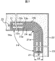
Next, a third embodiment of the present invention will be described with reference to FIG. FIG. 7: is principal part sectional drawing of the vacuum heat insulating material of 3rd Embodiment of this invention, and a refrigerator using the same. The third embodiment is different from the first embodiment in the points described below, and the other points are basically the same as those in the first embodiment, and thus redundant description is omitted.
図7において、真空断熱材70は冷蔵庫等の断熱壁の曲げ部24の内箱面21aの形状に沿って該内箱面21aに密着するように配設された真空断熱材であり、ガスバリア性を有する外被材71中に、後述する複数の内袋74a、74bを設置して、該外被材71中を所定の真空度にて真空封止して構成してある。
In FIG. 7, a vacuum
内袋74a、74bは、夫々、金属製フィルム或いは合成樹脂製フィルム73a、73bを挟んだ芯材72a、72bを脱気圧縮して収納するように構成されている。また、内袋74a、74bは、真空断熱材70を曲げたときに、曲げ応力により、外被材71との間で互いにずれることが出来るように、例えば、高密度ポリエチレン樹脂等の表面が滑らかな合成樹脂フィルムにより形成されている。
The
なお、図7は、外被材71中に、2個の内袋74a、74bを設けて、内袋74a、74bと外被材71とのずれを利用して曲げ易くしているが、真空断熱材の用途によっては、1個の内袋として、内袋内に、例えば、図6に例示したように複数枚のフィルムを介在しても良く、或いは、外被材71中に3個以上の内袋を設けても良い。
In FIG. 7, two
また、真空断熱材70は、その製造時は、該真空断熱材70自身の生産性の向上を図れるように、図3にて前述したように略平面形状として製造されることが望ましいが、図7に示す曲げ部24の曲げ角度Θ4の角度や曲げ曲面の半径R7或いは芯材の全体厚さt8寸法の大きさによっては、該真空断熱材70の製造時における状態を所定の角度に予め曲げて製造しても良い。
In addition, the vacuum
以上のように構成されているので、この第3実施形態は、フィルム73a、73bを挟んだ芯材72a、72bを脱気圧縮して収納する内袋74a、74bと、この内袋74a、74bを収納し、該内袋74a、74bとの間でずれが生じる外被材71とから構成したので、真空断熱材70を曲げるときに、内袋74a、74bと外被材71とのずれが生じ易いので、優れた断熱性能を保持したまま、形状折り曲げ性と形状保持性を有する真空断熱材及び真空断熱材を用いた冷蔵庫を提供できる。
Since it is configured as described above, in the third embodiment, the
20…冷蔵庫の箱体、21…内箱、22…発泡断熱材、23…外箱、24…曲げ部(変形部)、30、40、60、70…真空断熱材、31、41、61、71…外被材、32、42、62a、62b、62c、62d、62e、72a、72b…芯材、33、43、63a、63b、63c、63d、73a、73b…フィルム(変形保持部材)、50…断熱壁、54…測定冶具、74a、74b…内袋。 20 ... Refrigerator box, 21 ... Inner box, 22 ... Foam insulation, 23 ... Outer box, 24 ... Bending part (deformation part), 30, 40, 60, 70 ... Vacuum insulation, 31, 41, 61, 71 ... Cover material, 32, 42, 62a, 62b, 62c, 62d, 62e, 72a, 72b ... Core material, 33, 43, 63a, 63b, 63c, 63d, 73a, 73b ... Film (deformation holding member), 50 ... heat insulation wall, 54 ... measuring jig, 74a, 74b ... inner bag.
Claims (11)
前記芯材は結合剤を含まない無機もしくは有機の繊維重合体で形成すると共に、
前記外被材内に前記芯材と共に変形可能で且つ曲げ荷重を加えて曲げたときの圧縮応力或いは引っ張り応力により前記芯材とずれを生じさせ変形後の前記曲げ荷重が解除された該芯材形状を保持可能な変形保持部材が配置された
ことを特徴とする真空断熱材。 A vacuum heat insulating material obtained by vacuum-sealing a core material in a jacket material having gas barrier properties,
The core material is formed of an inorganic or organic fiber polymer containing no binder ,
The core material wherein the bending load after deformation is caused the core material and the deviation by compression stress or tensile stress when the and bending load deformable together with the core material bent in addition to the outer covering material within is released A vacuum heat insulating material characterized in that a deformation holding member capable of holding a shape is disposed.
前記芯材は結合剤を含まない無機もしくは有機の繊維重合体で形成すると共に、
前記外被材内に前記芯材と共に変形し且つ曲げ荷重を加えて曲げたときの圧縮応力或いは引っ張り応力により該芯材とずれを生じさせ変形後の前記曲げ荷重が解除された該芯材形状を保持する変形保持部材を配置して前記真空断熱材を構成し、
前記真空断熱材を前記外箱または前記内箱の変形部に沿って変形して配置した
ことを特徴とする冷蔵庫。 A vacuum heat insulating material obtained by vacuum-sealing a core material in a jacket material having a gas barrier property is disposed in a space formed by the outer box and the inner box, and a foam heat insulating material is provided in the space around the vacuum heat insulating material. In a refrigerator filled with
The core material is formed of an inorganic or organic fiber polymer containing no binder ,
Core material shape the bending load after deformation is produced core material and the deviation is canceled by the compression stress or tensile stress when the bent adding deformed and bending load with the core material in the outer covering material in The vacuum heat insulating material is configured by arranging a deformation holding member that holds
The refrigerator, wherein the vacuum heat insulating material is deformed and arranged along a deformed portion of the outer box or the inner box.
Priority Applications (2)
| Application Number | Priority Date | Filing Date | Title |
|---|---|---|---|
| JP2005242277A JP4580843B2 (en) | 2005-08-24 | 2005-08-24 | Vacuum heat insulating material and refrigerator using the same |
| CNB2006101159415A CN100441932C (en) | 2005-08-24 | 2006-08-18 | Vacuum thermal insulating material and refrigerator using the same |
Applications Claiming Priority (1)
| Application Number | Priority Date | Filing Date | Title |
|---|---|---|---|
| JP2005242277A JP4580843B2 (en) | 2005-08-24 | 2005-08-24 | Vacuum heat insulating material and refrigerator using the same |
Publications (3)
| Publication Number | Publication Date |
|---|---|
| JP2007056972A JP2007056972A (en) | 2007-03-08 |
| JP2007056972A5 JP2007056972A5 (en) | 2009-08-20 |
| JP4580843B2 true JP4580843B2 (en) | 2010-11-17 |
Family
ID=37778151
Family Applications (1)
| Application Number | Title | Priority Date | Filing Date |
|---|---|---|---|
| JP2005242277A Expired - Fee Related JP4580843B2 (en) | 2005-08-24 | 2005-08-24 | Vacuum heat insulating material and refrigerator using the same |
Country Status (2)
| Country | Link |
|---|---|
| JP (1) | JP4580843B2 (en) |
| CN (1) | CN100441932C (en) |
Cited By (2)
| Publication number | Priority date | Publication date | Assignee | Title |
|---|---|---|---|---|
| US11448355B2 (en) | 2021-01-12 | 2022-09-20 | Whirlpool Corporation | Vacuum insulated refrigerator structure with feature for controlling deformation and improved air withdrawal |
| US11614271B2 (en) | 2020-12-29 | 2023-03-28 | Whirlpool Corporation | Vacuum insulated structure with sheet metal features to control vacuum bow |
Families Citing this family (19)
| Publication number | Priority date | Publication date | Assignee | Title |
|---|---|---|---|---|
| JP4685828B2 (en) * | 2007-04-18 | 2011-05-18 | シャープ株式会社 | refrigerator |
| JP2009228886A (en) * | 2008-03-25 | 2009-10-08 | Mitsubishi Electric Corp | Vacuum heat insulating material and heat insulating box using the same |
| JP5193713B2 (en) * | 2008-07-17 | 2013-05-08 | 日立アプライアンス株式会社 | Freezer refrigerator |
| JP5162377B2 (en) * | 2008-08-28 | 2013-03-13 | 日立アプライアンス株式会社 | Vacuum heat insulating material, heat insulating box using the same, and refrigerator |
| WO2010073762A1 (en) | 2008-12-26 | 2010-07-01 | 三菱電機株式会社 | Vacuum insulation material, and heat-insulating box, refrigerator, freezing/air-conditioning apparatus, hot-water supply device, and appliance each employing vacuum insulation material, and process for producing vacuum insulation material |
| JP5312605B2 (en) | 2009-10-16 | 2013-10-09 | 三菱電機株式会社 | Vacuum insulation, refrigerator and equipment |
| JP5241925B2 (en) | 2009-10-16 | 2013-07-17 | 三菱電機株式会社 | Vacuum heat insulating material manufacturing apparatus, vacuum heat insulating material manufacturing method, vacuum heat insulating material, refrigerator and equipment |
| US9103482B2 (en) | 2009-10-19 | 2015-08-11 | Mitsubishi Electric Corporation | Vacuum heat insulating material, heat insulating box, refrigerator, refrigerating/air-conditioning apparatus, water heater, appliance, and manufacturing method of vacuum heat insulating material |
| CN101900473A (en) * | 2010-07-27 | 2010-12-01 | 王欣南 | Built-in integral L-shaped vacuum heat insulation slab for refrigerator and processing method thereof |
| JP2013088036A (en) * | 2011-10-19 | 2013-05-13 | Hitachi Appliances Inc | Thermal insulation box, refrigerator, and storage type water heater |
| JP5886017B2 (en) * | 2011-12-06 | 2016-03-16 | 株式会社東芝 | Vacuum insulation panel and refrigerator using the same |
| CN103542234A (en) * | 2012-07-16 | 2014-01-29 | 苏州维艾普新材料有限公司 | Dry method extra-fine glass wool vacuum insulated panel core material and preparation method thereof |
| JP6892414B2 (en) * | 2013-06-25 | 2021-06-23 | 東芝ライフスタイル株式会社 | refrigerator |
| JP6184841B2 (en) * | 2013-11-13 | 2017-08-23 | 日立アプライアンス株式会社 | Vacuum insulation material and equipment using the same |
| JP2017002949A (en) * | 2015-06-08 | 2017-01-05 | 日立アプライアンス株式会社 | Vacuum heat insulation material and equipment using the same |
| KR102442069B1 (en) * | 2015-10-19 | 2022-09-13 | 삼성전자주식회사 | Refrigerator amd producing method of same |
| CN108058919A (en) * | 2017-12-28 | 2018-05-22 | 兰考县鸿运运输有限公司 | Attemperator in a kind of transportational process |
| JP7215202B2 (en) * | 2019-02-13 | 2023-01-31 | 日本製鉄株式会社 | vacuum insulation panel |
| JP2019109042A (en) * | 2019-03-04 | 2019-07-04 | 東芝ライフスタイル株式会社 | refrigerator |
Citations (3)
| Publication number | Priority date | Publication date | Assignee | Title |
|---|---|---|---|---|
| JP2002081596A (en) * | 2000-09-06 | 2002-03-22 | Matsushita Refrig Co Ltd | Vacuum heat insulating material, method of manufacturing the same, refrigerating, equipment notebook type computer, electric water boiler and oven range |
| JP2002179158A (en) * | 2000-12-15 | 2002-06-26 | Honda Access Corp | Heat insulating container |
| JP2007046628A (en) * | 2005-08-05 | 2007-02-22 | Nissan Motor Co Ltd | Heat insulating material |
Family Cites Families (13)
| Publication number | Priority date | Publication date | Assignee | Title |
|---|---|---|---|---|
| JPS5747506Y2 (en) * | 1975-06-17 | 1982-10-19 | ||
| JPS61241594A (en) * | 1985-04-19 | 1986-10-27 | 松下電器産業株式会社 | Vacuum heat-insulating material |
| JPS6210580A (en) * | 1985-07-08 | 1987-01-19 | 凸版印刷株式会社 | Heat-insulating panel |
| JPH04337195A (en) * | 1991-05-14 | 1992-11-25 | Hitachi Ltd | Vacuum heat insulator |
| JP2002310384A (en) * | 2001-04-11 | 2002-10-23 | Matsushita Refrig Co Ltd | Vacuum heat insulation material, refrigerating appliance with vacuum heat insulation material, electric water heater, and oven-range |
| JP2002317897A (en) * | 2001-04-19 | 2002-10-31 | Matsushita Refrig Co Ltd | Vacuum heat insulation material, heat insulated container, refrigerator, and rice cooker |
| JP2004197954A (en) * | 2002-12-05 | 2004-07-15 | Matsushita Refrig Co Ltd | Vacuum heat insulating material |
| JP3559035B2 (en) * | 2002-12-05 | 2004-08-25 | 松下冷機株式会社 | Vacuum insulation material, method of manufacturing the same, and cold protection equipment and personal computer using vacuum insulation material |
| JP2004308691A (en) * | 2003-04-02 | 2004-11-04 | Nisshinbo Ind Inc | Vacuum heat insulating material and manufacturing method thereof |
| WO2005003618A1 (en) * | 2003-07-04 | 2005-01-13 | Matsushita Electric Industrial Co., Ltd. | Vacuum thermal insulation material and equipment using the same |
| JP2005127409A (en) * | 2003-10-23 | 2005-05-19 | Matsushita Electric Ind Co Ltd | Vacuum heat insulation material, freezing device and cooling-warming device using vacuum heat insulation material |
| JP2005163989A (en) * | 2003-12-05 | 2005-06-23 | Matsushita Electric Ind Co Ltd | Vacuum insulating material and using method of same |
| JP3578172B1 (en) * | 2003-12-19 | 2004-10-20 | 松下電器産業株式会社 | Vacuum insulation, refrigerators and refrigerators |
-
2005
- 2005-08-24 JP JP2005242277A patent/JP4580843B2/en not_active Expired - Fee Related
-
2006
- 2006-08-18 CN CNB2006101159415A patent/CN100441932C/en not_active Expired - Fee Related
Patent Citations (3)
| Publication number | Priority date | Publication date | Assignee | Title |
|---|---|---|---|---|
| JP2002081596A (en) * | 2000-09-06 | 2002-03-22 | Matsushita Refrig Co Ltd | Vacuum heat insulating material, method of manufacturing the same, refrigerating, equipment notebook type computer, electric water boiler and oven range |
| JP2002179158A (en) * | 2000-12-15 | 2002-06-26 | Honda Access Corp | Heat insulating container |
| JP2007046628A (en) * | 2005-08-05 | 2007-02-22 | Nissan Motor Co Ltd | Heat insulating material |
Cited By (4)
| Publication number | Priority date | Publication date | Assignee | Title |
|---|---|---|---|---|
| US11614271B2 (en) | 2020-12-29 | 2023-03-28 | Whirlpool Corporation | Vacuum insulated structure with sheet metal features to control vacuum bow |
| US11808514B2 (en) | 2020-12-29 | 2023-11-07 | Whirlpool Corporation | Vacuum insulated structure with sheet metal features to control vacuum bow |
| US11448355B2 (en) | 2021-01-12 | 2022-09-20 | Whirlpool Corporation | Vacuum insulated refrigerator structure with feature for controlling deformation and improved air withdrawal |
| US11708935B2 (en) | 2021-01-12 | 2023-07-25 | Whirlpool Corporation | Vacuum insulated refrigerator structure with feature for controlling deformation and improved air withdrawal |
Also Published As
| Publication number | Publication date |
|---|---|
| JP2007056972A (en) | 2007-03-08 |
| CN100441932C (en) | 2008-12-10 |
| CN1920367A (en) | 2007-02-28 |
Similar Documents
| Publication | Publication Date | Title |
|---|---|---|
| JP4580843B2 (en) | Vacuum heat insulating material and refrigerator using the same | |
| KR100540522B1 (en) | Vacuum insulating material and device using the same | |
| JP5624305B2 (en) | Insulated container | |
| JP2013088036A (en) | Thermal insulation box, refrigerator, and storage type water heater | |
| JP3513142B2 (en) | Vacuum insulation, insulation, insulation box, insulation door, storage and refrigerator | |
| US20120132659A1 (en) | Vacuum insulation member, regisrator having vacuum insulation member, and method for fabricating vacuum insulation member | |
| JP2009228917A (en) | Refrigerator | |
| JP2007056972A5 (en) | ||
| JP2009024922A (en) | Refrigerator | |
| JP5372877B2 (en) | Vacuum heat insulating material and refrigerator using the same | |
| JP2007113748A (en) | Method of manufacturing heat insulating wall, heat insulating unit, and heat insulating material | |
| CN104455935A (en) | Vacuum heat-insulating material, thermal-insulating case and a manufacturing method of the vacuum heat-insulating material | |
| KR100691917B1 (en) | Refrigerator | |
| JP2011099566A (en) | Vacuum heat insulating panel and refrigerator | |
| JP5646241B2 (en) | refrigerator | |
| JP6469232B2 (en) | refrigerator | |
| JP5401422B2 (en) | Vacuum heat insulating material and refrigerator using the same | |
| JP5982276B2 (en) | Refrigerator using vacuum heat insulating material and vacuum heat insulating material | |
| JP5372878B2 (en) | Vacuum heat insulating material and refrigerator equipped with the same | |
| KR101714569B1 (en) | Vacuum insulation panel, refrigerator with vacuum insulation panel and manufacturing method for vacuum insulation panel | |
| JP2017002949A (en) | Vacuum heat insulation material and equipment using the same | |
| JP6000922B2 (en) | Vacuum heat insulating material and cooling / heating equipment using the same | |
| JP2010001922A (en) | Vacuum heat insulating material, heat insulating box body using this material, and method for manufacturing vacuum heat insulating material | |
| JP2006029413A (en) | Vacuum heat insulating material and its manufacturing method | |
| JP5984022B2 (en) | refrigerator |
Legal Events
| Date | Code | Title | Description |
|---|---|---|---|
| A621 | Written request for application examination |
Free format text: JAPANESE INTERMEDIATE CODE: A621 Effective date: 20070601 |
|
| A521 | Written amendment |
Free format text: JAPANESE INTERMEDIATE CODE: A523 Effective date: 20090703 |
|
| A977 | Report on retrieval |
Free format text: JAPANESE INTERMEDIATE CODE: A971007 Effective date: 20090709 |
|
| A131 | Notification of reasons for refusal |
Free format text: JAPANESE INTERMEDIATE CODE: A131 Effective date: 20091208 |
|
| A521 | Written amendment |
Free format text: JAPANESE INTERMEDIATE CODE: A523 Effective date: 20100204 |
|
| TRDD | Decision of grant or rejection written | ||
| A01 | Written decision to grant a patent or to grant a registration (utility model) |
Free format text: JAPANESE INTERMEDIATE CODE: A01 Effective date: 20100810 |
|
| A01 | Written decision to grant a patent or to grant a registration (utility model) |
Free format text: JAPANESE INTERMEDIATE CODE: A01 |
|
| A61 | First payment of annual fees (during grant procedure) |
Free format text: JAPANESE INTERMEDIATE CODE: A61 Effective date: 20100830 |
|
| FPAY | Renewal fee payment (event date is renewal date of database) |
Free format text: PAYMENT UNTIL: 20130903 Year of fee payment: 3 |
|
| R150 | Certificate of patent or registration of utility model |
Ref document number: 4580843 Country of ref document: JP Free format text: JAPANESE INTERMEDIATE CODE: R150 Free format text: JAPANESE INTERMEDIATE CODE: R150 |
|
| S531 | Written request for registration of change of domicile |
Free format text: JAPANESE INTERMEDIATE CODE: R313531 |
|
| S533 | Written request for registration of change of name |
Free format text: JAPANESE INTERMEDIATE CODE: R313533 |
|
| R350 | Written notification of registration of transfer |
Free format text: JAPANESE INTERMEDIATE CODE: R350 |
|
| LAPS | Cancellation because of no payment of annual fees |