JP2007113748A - Method of manufacturing heat insulating wall, heat insulating unit, and heat insulating material - Google Patents

Method of manufacturing heat insulating wall, heat insulating unit, and heat insulating material Download PDF

Info

Publication number
JP2007113748A
JP2007113748A JP2005307926A JP2005307926A JP2007113748A JP 2007113748 A JP2007113748 A JP 2007113748A JP 2005307926 A JP2005307926 A JP 2005307926A JP 2005307926 A JP2005307926 A JP 2005307926A JP 2007113748 A JP2007113748 A JP 2007113748A
Authority
JP
Japan
Prior art keywords
heat insulating
insulating material
wall
covering
vacuum
Prior art date
Legal status (The legal status is an assumption and is not a legal conclusion. Google has not performed a legal analysis and makes no representation as to the accuracy of the status listed.)
Pending
Application number
JP2005307926A
Other languages
Japanese (ja)
Other versions
JP2007113748A5 (en
Inventor
Hisashi Echigoya
恒 越後屋
Kuninari Araki
邦成 荒木
Current Assignee (The listed assignees may be inaccurate. Google has not performed a legal analysis and makes no representation or warranty as to the accuracy of the list.)
Hitachi Appliances Inc
Original Assignee
Hitachi Appliances Inc
Priority date (The priority date is an assumption and is not a legal conclusion. Google has not performed a legal analysis and makes no representation as to the accuracy of the date listed.)
Filing date
Publication date
Application filed by Hitachi Appliances Inc filed Critical Hitachi Appliances Inc
Priority to JP2005307926A priority Critical patent/JP2007113748A/en
Publication of JP2007113748A publication Critical patent/JP2007113748A/en
Publication of JP2007113748A5 publication Critical patent/JP2007113748A5/ja
Pending legal-status Critical Current

Links

Images

Abstract

<P>PROBLEM TO BE SOLVED: To facilitate manufacture with excellent reliability and handling performance in a method of manufacturing a heat insulating wall. <P>SOLUTION: The method of manufacturing the heat insulating wall is a method of forming the heat insulating wall from a heat insulating material 100, an external wall 201 and an internal wall 202 by covering a vacuum heat insulating material 103 with an elastic covering material 102 to store them in an outer bag 101, reducing pressure in the outer bag 101 and sealing the outer bag 101 in the compressed state of the covering material 102 to form the heat insulating material 100, installing the heat insulating material 100 between the external wall 201 and the internal wall 202 and releasing the sealed state of the outer bag 101 of the heat insulating material 100, thereby restoring the covering material 102 to clamp the heat insulating material 100 between the external wall 201 and the internal wall 202. <P>COPYRIGHT: (C)2007,JPO&INPIT

Description

本発明は、断熱壁の製造方法、並びに断熱ユニット及び断熱材に係り、例えば、冷蔵庫を含む家電品や住宅や車輌等の断熱部分に用いられる断熱壁の製造方法、並びに断熱ユニット及び断熱材に好適なものである。   The present invention relates to a method for manufacturing a heat insulating wall, a heat insulating unit, and a heat insulating material, for example, a method for manufacturing a heat insulating wall used in a heat insulating portion of a household appliance, a house, a vehicle, or the like including a refrigerator, and a heat insulating unit and a heat insulating material. Is preferred.

地球温暖化防止に対する観点から、家電品や住宅や車輌等の省エネ性能の向上が望まれている。そして、近年、省エネのために、家電品や住宅等の断熱壁内に真空断熱材を採用して、断熱壁の熱漏洩量を低減することが提案されている。   From the viewpoint of preventing global warming, it is desired to improve the energy saving performance of home appliances, houses, vehicles, and the like. In recent years, in order to save energy, it has been proposed to employ a vacuum heat insulating material in heat insulating walls of home appliances and houses to reduce the amount of heat leakage of the heat insulating walls.

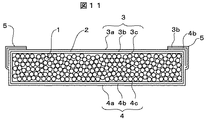
一般的な真空断熱材の一例について、図11を用いて具体的に説明する。この真空断熱材は、硬質ウレタンフォームを粉砕して得た粉末からなる芯材1と、通気性を有する不織布2とを、ラミネートフィルムからなる外被材3,4中に所定の真空度で真空封止して構成したものである。外被材3は、最外層3aにポリエチレンテレフタレート樹脂、中間層3bにガスバリア性を有するアルミニウム箔、最内層3cに熱溶着可能な高密度ポリエチレン樹脂からなるプラスチックラミネートフィルムである。外被材4は、最外層4aにナイロン樹脂、中間層4bにガスバリア性を有するアルミニウム蒸着層、最内層4cに熱溶着可能な高密度ポリエチレン樹脂からなるプラスチックラミネートフィルムである。外被材3の最内層3cと外被材4の最内層4cとを耳部5により熱溶着して袋状に形成してある。   An example of a general vacuum heat insulating material will be specifically described with reference to FIG. In this vacuum heat insulating material, a core material 1 made of powder obtained by pulverizing a rigid urethane foam and a non-woven fabric 2 having air permeability are vacuumed at a predetermined degree of vacuum in jacket materials 3 and 4 made of a laminate film. It is configured by sealing. The outer covering material 3 is a plastic laminate film made of a polyethylene terephthalate resin for the outermost layer 3a, an aluminum foil having a gas barrier property for the intermediate layer 3b, and a high-density polyethylene resin that can be thermally welded to the innermost layer 3c. The outer cover material 4 is a plastic laminate film made of nylon resin for the outermost layer 4a, an aluminum vapor deposition layer having gas barrier properties for the intermediate layer 4b, and a high-density polyethylene resin that can be thermally welded to the innermost layer 4c. The innermost layer 3c of the outer jacket material 3 and the innermost layer 4c of the outer jacket material 4 are thermally welded by the ear portion 5 to form a bag shape.

そして、ポリエチレンテレフタレート樹脂や高密度ポリエチレン樹脂、ナイロン樹脂等よりなるプラスチックラミネートフィルム3や4は、真空封止された芯材部1より熱伝導率が大きいので、その厚さを150μm程度以下に薄くして該部よりの熱伝導を少なくするように設定してある。   The plastic laminate films 3 and 4 made of polyethylene terephthalate resin, high-density polyethylene resin, nylon resin, or the like have a thermal conductivity larger than that of the vacuum-sealed core part 1, so that the thickness is reduced to about 150 μm or less. Thus, the heat conduction from the portion is set to be small.

特に、プラスチックラミネートフィルム3や4中にあって、ガスバリア性を受け持つアルミニウム箔3bやアルミニウム蒸着層4bは、それ自身が熱の良伝導物質であるために、良伝導性によるヒートブリッジにより、真空断熱材としての断熱性能を低下させないように、アルミニウム箔3bやアルミニウム蒸着層4bの厚さを、通常、15μm程度以下に設定してある。   In particular, the aluminum foil 3b and the aluminum vapor deposition layer 4b, which are in the plastic laminate films 3 and 4 and are responsible for gas barrier properties, are themselves heat-conducting materials. The thickness of the aluminum foil 3b and the aluminum vapor deposition layer 4b is usually set to about 15 μm or less so as not to deteriorate the heat insulating performance as a material.

真空断熱材を用いた断熱壁の従来例としては、例えば、特開2000−248653号公報(特許文献1)や特開2003−14368公報(特許文献2)に提案されているものがある。   As a conventional example of the heat insulation wall using a vacuum heat insulating material, there exist some which are proposed by Unexamined-Japanese-Patent No. 2000-248653 (patent document 1) and Unexamined-Japanese-Patent No. 2003-14368 (patent document 2), for example.

特許文献1に記載のものは、真空断熱体と、真空断熱体の少なくとも1面を覆ってなる硬質ウレタンフォーム等の樹脂発泡体と、真空断熱体と樹脂発泡体とからなる断熱体の少なくとも相対する2面を覆った面材とからなり、面材間に配設されている真空断熱体の配設位置を面材の少なくとも1表面に明記することにより、断熱壁の熱漏洩量を低減すると共に、釘打ちあるいは切断しても真空断熱体が破袋しないようにしたものである。   The one described in Patent Document 1 is at least relative to a vacuum insulator, a resin foam such as a rigid urethane foam covering at least one surface of the vacuum insulator, and a heat insulator made of a vacuum insulator and a resin foam. The amount of heat leakage of the heat insulating wall is reduced by clearly specifying the position of the vacuum heat insulating material disposed between the face materials on at least one surface of the face material. At the same time, the vacuum insulator is not broken even when nailing or cutting.

また、特許文献2に記載のものは、外箱と内箱との間に硬質ウレタンフォームと真空断熱材とを備え、外箱の表面積に対して真空断熱材の被覆率を50%を超え80%以下とし、真空断熱材の表裏面に均質なウレタン層を形成し、真空断熱材と外箱との距離が、真空断熱材と内箱との距離より小さくすることにより、外箱外観の美しさを維持すると共に、断熱性能の低下を引き起こすことがなく省エネ効果を高めるようにしたものである。   Moreover, the thing of patent document 2 is equipped with a hard urethane foam and a vacuum heat insulating material between an outer box and an inner box, and the coverage of a vacuum heat insulating material exceeds 50% with respect to the surface area of an outer box, and 80 % Or less, and a uniform urethane layer is formed on the front and back surfaces of the vacuum heat insulating material, and the distance between the vacuum heat insulating material and the outer box is smaller than the distance between the vacuum heat insulating material and the inner box. The energy saving effect is enhanced while maintaining the strength and without causing deterioration of the heat insulation performance.

特開2000−248653号公報JP 2000-248653 A 特開2003−14368公報JP 2003-14368 A

真空断熱材は、図11を用いて上述したように、ガスバリア性を有するラミネートフィルムからなる外被材中に、所定の厚さを有する芯材を真空封止して形成しており、外被材自身が熱伝導性を有するので、該部よりの熱伝導を少なくするために、その厚さを薄く設定してある。従って、特許文献1、2のように、外壁(外箱)と内壁(内箱)との間に真空断熱材を硬質ウレタンフォームと共に設置して断熱壁を形成する場合に、真空断熱材の運搬や保管時に、万一、真空断熱材に他の真空断熱材や他の部品や機材等が当接すると、真空断熱材の外被材に傷がつき、この傷つきにより外被材のガスバリア性が劣化し、長期間経過後には真空断熱材の真空度が低下して断熱性能が低下する恐れがあった。このため、真空断熱材の取り扱い性と信頼性とを両立させることが課題となっていた。   As described above with reference to FIG. 11, the vacuum heat insulating material is formed by vacuum-sealing a core material having a predetermined thickness in a jacket material made of a laminate film having gas barrier properties. Since the material itself has thermal conductivity, its thickness is set thin in order to reduce heat conduction from the portion. Therefore, as in Patent Documents 1 and 2, when a heat insulating wall is formed by installing a vacuum heat insulating material together with a hard urethane foam between an outer wall (outer box) and an inner wall (inner box), the vacuum heat insulating material is transported. In the unlikely event that other vacuum insulation materials or other parts or equipment come into contact with the vacuum insulation material during storage, the outer insulation material of the vacuum insulation material will be damaged. It deteriorated, and after a long period of time, the vacuum degree of the vacuum heat insulating material was lowered, and there was a fear that the heat insulation performance was lowered. For this reason, it became a subject to make the handleability and reliability of a vacuum heat insulating material compatible.

また、特許文献1、2の断熱壁では、真空断熱材を外壁(外箱)及び内壁(内箱)との間に配置した後に、真空断熱材と外壁(外箱)及び内壁(内箱)と隙間に硬質ウレタンフォームを充填しなければならない、という課題があった。   Moreover, in the heat insulation wall of patent document 1, 2, after arrange | positioning a vacuum heat insulating material between an outer wall (outer box) and an inner wall (inner box), a vacuum heat insulating material, an outer wall (outer box), and an inner wall (inner box) There was a problem that hard urethane foam had to be filled in the gaps.

本発明の第1の目的は、信頼性及び取り扱い性に優れ、製造が容易な断熱壁の製造方法を提供することにある。   A first object of the present invention is to provide a method for manufacturing a heat insulating wall that is excellent in reliability and handleability and is easy to manufacture.

本発明の第2の目的は、信頼性及び取り扱い性に優れた断熱材及び断熱ユニットを提供することにある。   The second object of the present invention is to provide a heat insulating material and a heat insulating unit excellent in reliability and handleability.

前述の第1の目的を達成するための本発明の第1の態様は、弾性を有する被覆材で真空断熱材を覆って外袋内に収納し、この外袋の内部を減圧すると共に前記被覆材を圧縮した状態で該外袋を密閉して断熱材を形成し、この断熱材を外壁と内壁との間に設置すると共に該断熱材の外袋の密閉を解除することにより前記被覆材を復元させて前記断熱材を前記外壁と前記内壁との間に挟持させて、この断熱材と前記外壁と前記内壁とから断熱壁を形成する断熱壁の製造方法である。
ことにある。
The first aspect of the present invention for achieving the first object described above is to cover the vacuum heat insulating material with an elastic covering material and store it in the outer bag, decompress the inside of the outer bag, and In the compressed state, the outer bag is sealed to form a heat insulating material, and the heat insulating material is installed between the outer wall and the inner wall, and the outer bag of the heat insulating material is released from the sealing to It is a manufacturing method of the heat insulation wall which makes it restore | restore and clamps the said heat insulating material between the said outer wall and the said inner wall, and forms a heat insulating wall from this heat insulating material, the said outer wall, and the said inner wall.
There is.

また、前述の第2の目的を達成するための本発明の第2の態様は、外壁と、内壁と、前記外壁と前記内壁との間に設置された断熱材と、からなる断熱ユニットであって、前記断熱材は、真空断熱材と、この真空断熱材を覆うと共に弾性を有する被覆材と、前記真空断熱材を覆った前記被覆材を覆う外袋とを備えているものである。   Further, a second aspect of the present invention for achieving the second object described above is a heat insulating unit comprising an outer wall, an inner wall, and a heat insulating material installed between the outer wall and the inner wall. The heat insulating material includes a vacuum heat insulating material, a covering material that covers the vacuum heat insulating material and has elasticity, and an outer bag that covers the covering material that covers the vacuum heat insulating material.

係る本発明の第2の態様におけるより好ましい具体的構成例は次の通りである。
(1)前記真空断熱材は、パネル状の芯材と、この芯材を包み且つこの芯材を含む内部を真空状態にした外被材とを備えてパネル状に形成され、前記被覆材は前記真空断熱材の平面部両側を覆うように設置されていること。
(2)前記(1)において、前記被覆材及び前記外袋は前記真空断熱材の周囲に形成される耳部を含む大きさより幅広に形成されてこの耳部を覆っていること。
(3)前記(2)において、前記真空断熱材と前記被覆材との間に釘や螺子等に対する耐突き刺し強度を有する補強部材を設置したこと。
A more preferable specific configuration example in the second aspect of the present invention is as follows.
(1) The vacuum heat insulating material is formed in a panel shape including a panel-shaped core material and a jacket material that wraps the core material and evacuates the inside including the core material, and the covering material is It is installed so as to cover both sides of the flat part of the vacuum heat insulating material.
(2) In the above (1), the covering material and the outer bag are formed wider than a size including an ear portion formed around the vacuum heat insulating material to cover the ear portion.
(3) In (2), a reinforcing member having a puncture resistance against a nail, a screw or the like is installed between the vacuum heat insulating material and the covering material.

また、前述の第2の目的を達成するための本発明の第3の態様は、外壁と、内壁と、前記外壁と前記内壁との間に設置された断熱材とからなる断熱ユニットであって、前記断熱材は、真空断熱材と、この真空断熱材を覆うと共に弾性を有する被覆材と、前記真空断熱材を覆った前記被覆材を覆う外袋とを備えて構成され、前記被覆材は無機繊維あるいは有機繊維からなる繊維重合体で構成されており、前記断熱材は前記被覆材の弾性により両側平面部を前記外壁及び前記内壁に当接するように設置されているものである。   A third aspect of the present invention for achieving the second object described above is a heat insulating unit comprising an outer wall, an inner wall, and a heat insulating material installed between the outer wall and the inner wall. The heat insulating material includes a vacuum heat insulating material, a covering material that covers the vacuum heat insulating material and has elasticity, and an outer bag that covers the covering material that covers the vacuum heat insulating material. It is comprised with the fiber polymer which consists of an inorganic fiber or an organic fiber, and the said heat insulating material is installed so that a both-sides plane part may contact | abut to the said outer wall and the said inner wall by the elasticity of the said coating | covering material.

係る本発明の第3の態様におけるより好ましい具体的構成例は次の通りである。
(1)前記被覆材はブチルゴムやグラスウール等の遮音性や吸音性を有する材料で形成したこと。
A more preferable specific configuration example in the third aspect of the present invention is as follows.
(1) The covering material is formed of a material having sound insulation and sound absorption properties such as butyl rubber and glass wool.

また、前述の第2の目的を達成するための本発明の第4の態様は、真空断熱材と、該真空断熱材を覆うと共に弾性を有する被覆材と、前記真空断熱材を覆った前記被覆材を覆う外袋と、を有して構成した断熱材である。   In addition, the fourth aspect of the present invention for achieving the second object described above includes a vacuum heat insulating material, a covering material that covers the vacuum heat insulating material and has elasticity, and the coating that covers the vacuum heat insulating material. And an outer bag covering the material.

係る本発明の第4の態様におけるより好ましい具体的構成例は次の通りである。
(1)前記真空断熱材は、パネル状の芯材と、該芯材を包み且つ該芯材を含む内部を真空状態にした外被材とを備えてパネル状に形成され、前記被覆材は前記真空断熱材の平面部全体を両側から覆うように設置されていること。
(2)前記被覆材は無機繊維あるいは有機繊維からなる繊維重合体で構成され、前記外袋はその内部を減圧し前記被覆材を圧縮し密閉した状態で収納していること。
A more preferable specific configuration example in the fourth aspect of the present invention is as follows.
(1) The vacuum heat insulating material is formed in a panel shape including a panel-shaped core material and an outer jacket material that wraps the core material and evacuates the inside including the core material, and the covering material is It is installed so that the whole plane part of the said vacuum heat insulating material may be covered from both sides.
(2) The covering material is made of a fiber polymer made of inorganic fiber or organic fiber, and the outer bag is housed in a state where the inside is decompressed and the covering material is compressed and sealed.

本発明によれば、信頼性及び取り扱い性に優れ、製造が容易な断熱壁の製造方法を提供することができる。   ADVANTAGE OF THE INVENTION According to this invention, it can provide the manufacturing method of the heat insulation wall which is excellent in reliability and handleability, and is easy to manufacture.

また、本発明によれば、信頼性及び取り扱い性に優れた断熱材及び断熱ユニットを提供することができる。   Moreover, according to this invention, the heat insulating material and heat insulation unit excellent in reliability and handleability can be provided.

以下、本発明の複数の実施形態について図を用いて説明する。各実施形態の図における同一符号は同一物または相当物を示し、各実施形態の説明で述べる点以外については第1実施形態と基本的には同一であるので、重複する説明を省略する。
なお、本発明は、それぞれの実施形態を必要に応じて適宜に組み合わせることにより、さらに効果的なものとすることを含むものである。
(第1実施形態)
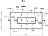
本発明の第1実施形態を、図1を用いて説明する。図1は本発明の第1実施形態に係る断熱材の断面図である。
Hereinafter, a plurality of embodiments of the present invention will be described with reference to the drawings. The same reference numerals in the drawings of the respective embodiments indicate the same or equivalent components, and are basically the same as those in the first embodiment except for the points described in the description of the respective embodiments.
In addition, this invention includes making it more effective by combining each embodiment suitably as needed.
(First embodiment)
A first embodiment of the present invention will be described with reference to FIG. FIG. 1 is a sectional view of a heat insulating material according to the first embodiment of the present invention.

断熱材100は、真空断熱材103と、この真空断熱材103を覆い、それ自身に可撓性と復元性を含む弾性を有し、この弾性により図3に示す状態にでき且つ図3の状態から図2の状態に復元可能な被覆材102と、被覆材102を覆う袋101とで構成してある。被覆材102は可撓性、復元性及び折り曲げ性を有するものである。   The heat insulating material 100 covers the vacuum heat insulating material 103 and the vacuum heat insulating material 103, and has elasticity including flexibility and resilience in itself, and can be in the state shown in FIG. 2 is configured by a covering material 102 that can be restored to the state of FIG. 2 and a bag 101 that covers the covering material 102. The covering material 102 has flexibility, resilience, and bendability.

真空断熱材103は、ガスバリア性を有する外被材103d、103e中に、無機繊維或いは有機繊維等の繊維重合体から成る芯材103fを所定の真空度で真空封止して、所定の断熱性能を有するように構成されている。芯材103fを構成する繊維重合体は無機繊維或いは有機繊維等の繊維層を複数枚重ねた繊維積層体で形成されていてもよい。ガスバリア性を有する外被材103dは、例えば、最外層にポリエチレンテレフタレート樹脂、中間層にガスバリア性を有するアルミニウム箔、最内層に熱溶着可能な高密度ポリエチレン樹脂からなるプラスチックラミネートフィルムである。ガスバリア性を有する外被材103eは、例えば、最外層にナイロン樹脂、中間層にガスバリア性を有するアルミニウム蒸着層を有するエチレン−ビニルアルコール共重合体樹脂、最内層に熱溶着可能な高密度ポリエチレン樹脂からなるプラスチックラミネートフィルムである。外被材103dと外被材103eとは、それぞれの最内層同士を耳部103gにより熱溶着して袋状に形成されている。   The vacuum heat insulating material 103 has a predetermined heat insulation performance by vacuum-sealing a core material 103f made of a fiber polymer such as inorganic fiber or organic fiber in a covering material 103d, 103e having gas barrier properties at a predetermined degree of vacuum. It is comprised so that it may have. The fiber polymer constituting the core material 103f may be formed of a fiber laminate in which a plurality of fiber layers such as inorganic fibers or organic fibers are stacked. The covering material 103d having a gas barrier property is, for example, a plastic laminate film made of a polyethylene terephthalate resin as an outermost layer, an aluminum foil having a gas barrier property as an intermediate layer, and a high-density polyethylene resin that can be thermally welded to the innermost layer. The jacket material 103e having a gas barrier property is, for example, a nylon resin as an outermost layer, an ethylene-vinyl alcohol copolymer resin having an aluminum vapor deposition layer having a gas barrier property as an intermediate layer, and a high-density polyethylene resin that can be thermally welded to the innermost layer. This is a plastic laminate film. The outer covering material 103d and the outer covering material 103e are formed in a bag shape by thermally welding the innermost layers thereof by the ear portion 103g.

ここで、プラスチックラミネートフィルムである外被材103d、103eは、真空封止された芯材103fより熱伝導率が大きいので、その厚さを150μm程度以下に薄くして外被材103d、103eよりの熱伝導を少なくするように設定してある。特に、プラスチックラミネートフィルム中にあって、ガスバリア性を受け持つアルミニウム箔やアルミニウム蒸着層は、それ自身が熱の良伝導物質であるために、この良熱伝導性によるヒートブリッジによる断熱性能の低下を抑制するように、アルミニウム箔やアルミニウム蒸着層の厚さを15μm程度以下に設定してある。   Here, the jacket materials 103d and 103e, which are plastic laminate films, have a higher thermal conductivity than the vacuum-sealed core material 103f. Therefore, the thickness is reduced to about 150 μm or less from the jacket materials 103d and 103e. Is set to reduce heat conduction. In particular, the aluminum foil and aluminum vapor deposition layer in the plastic laminate film, which is responsible for gas barrier properties, are themselves good heat conductors, so they suppress the deterioration of heat insulation performance due to heat bridges due to this good heat conductivity. As described above, the thickness of the aluminum foil or aluminum vapor deposition layer is set to about 15 μm or less.

従って、真空断熱材103の製造工程におけるハンドリング時や、真空断熱材として完成後の運搬時や保管時に、万一、真空断熱材103に他の部品や機材等が当接すると、薄く構成された外被材103d、103eに傷がつき、この傷つきにより厚さの薄いアルミニウム箔やアルミニウム蒸着層のガスバリア性が劣化する恐れがある。   Therefore, when handling in the manufacturing process of the vacuum heat insulating material 103, or during transportation or storage after completion as a vacuum heat insulating material, if the vacuum heat insulating material 103 comes into contact with other parts, equipment, etc., it is thinly configured. The covering materials 103d and 103e are damaged, and the gas barrier property of the thin aluminum foil or aluminum vapor deposition layer may be deteriorated due to the damage.

また、真空断熱材103の耳部103gは、前述したように、アルミニウム箔或いはアルミニウム蒸着層を含むプラスチックラミネートフィルムが二重になって溶着されている為、かなりの剛性を有するので、耳部103gが、他の真空断熱材や他の部材等に当接すると、互いに傷つく恐れがある。   Further, the ear 103g of the vacuum heat insulating material 103 has a considerable rigidity because the plastic laminate film including the aluminum foil or the aluminum vapor deposition layer is doubled and welded as described above. However, if they come into contact with other vacuum heat insulating materials or other members, they may be damaged.

そこで、本実施形態では、耳部103gを含む真空断熱材103全体を、それ自身に弾性を有する被覆材102で覆うことにより、他の部品からの耐当接性を向上させるように構成してある。   Therefore, in this embodiment, the entire vacuum heat insulating material 103 including the ear portion 103g is covered with a covering material 102 having elasticity by itself so as to improve the contact resistance from other components. is there.

なお、真空断熱材の製造上のハンドリング時に、剛性を有する耳部が他の部材に当接し難くするために、従来例では、図11に示すように、耳部5を真空断熱材の本体表面の外被材3に密着するように折り曲げるようにしていた。しかし、このようにすると、外被材3,4中のアルミニウム箔3bやアルミニウム蒸着層4bと耳部5内のアルミニウム箔3bやアルミニウム蒸着層4bとがヒートブリッジし易くなるので、真空断熱材としての断熱性能が低下してしまう恐れがある。そこで、本実施形態においては、図1に示すように、耳部103gは、真空断熱材103の表面に折り曲げないように構成するようにしている。即ち、被覆材102及び外袋101は真空断熱材103の周囲に形成される耳部103gを含む大きさより幅広に形成され、この耳部103gを覆うように構成されている。かかる構成によって、ヒートブリッジによる断熱性能の低下を抑制することができる。   In order to make it difficult for the rigid ear portion to come into contact with other members during handling of the vacuum heat insulating material, in the conventional example, as shown in FIG. 11, the ear portion 5 is attached to the surface of the main body of the vacuum heat insulating material. It was made to bend | fold so that it might closely_contact | adhere to the outer covering material 3. However, if this is done, the aluminum foil 3b or the aluminum vapor deposition layer 4b in the jacket materials 3 and 4 and the aluminum foil 3b or the aluminum vapor deposition layer 4b in the ear portion 5 are easily heat-bridged. There is a risk that the heat insulation performance of the will be reduced. Therefore, in this embodiment, as shown in FIG. 1, the ear portion 103 g is configured not to be bent on the surface of the vacuum heat insulating material 103. That is, the covering material 102 and the outer bag 101 are formed wider than the size including the ear portion 103g formed around the vacuum heat insulating material 103, and are configured to cover the ear portion 103g. With this configuration, it is possible to suppress a decrease in heat insulation performance due to the heat bridge.

また、断熱材100が、製造工程におけるハンドリング時や、完成後の運搬時や保管時に受ける当接力は、断熱材100の大きさや使用目的等により種々異なるため、図1に示す被覆材102の厚さ寸法t2a、t3a、t4a、t5aは、使用目的等により調節するのが望ましい。   In addition, the contact force that the heat insulating material 100 receives during handling in the manufacturing process, during transportation after completion, and during storage varies depending on the size of the heat insulating material 100, the purpose of use, and the like. Therefore, the thickness of the covering material 102 shown in FIG. The lengths t2a, t3a, t4a, and t5a are desirably adjusted according to the purpose of use.

また、被覆材102は、真空断熱材103への傷つき防止機能と、前述した弾性とを備えている材料であればよいが、必要に応じて所定の機能を合せ有する材料を用いることが好ましい。例えば、断熱性を兼備するものであれば、ポリエステルやポリプロピレン等の有機合成化学繊維、或いは、木綿や羊毛等の天然繊維等が使用可能であるが、自然界の生態系循環サイクルに負荷となる有機物質を少なくするためには、グラスウールやロックウール等の無機繊維が望ましい。また、例えば、防音性を兼備するものであれば、ブチルゴム発泡体等や石綿等が使用可能であるが、有機物質や作業環境を考慮すると、グラスウール等の無機繊維が望ましい。   The covering material 102 may be a material having a function of preventing damage to the vacuum heat insulating material 103 and the elasticity described above, but it is preferable to use a material having a predetermined function as required. For example, organic synthetic chemical fibers such as polyester and polypropylene or natural fibers such as cotton and wool can be used as long as they have heat insulation properties. In order to reduce the substance, inorganic fibers such as glass wool and rock wool are desirable. For example, butyl rubber foam or asbestos can be used as long as it has soundproofing properties, but inorganic fibers such as glass wool are desirable in consideration of organic substances and working environment.

また、被覆材102を覆う外袋101は、断熱材100を運搬や保管する時、或いは、圧縮過程時に、被覆材102を構成する材料が散らばったり、或いは粉塵となって飛散したりしないように、被覆材102を覆う機能を有すれば、材料としては特に限定されるものではない。例えば、ポリエチレン樹脂等の合成樹脂やアルミニウム等の金属箔、或いは、紙やゴム等の自然系材料等が使用可能である。また、その形態も図1に示すような、上シート101dと下シート101eをその周縁部101gで溶着或いは接着して袋状にする方法のみならず、チューブ状材料の開口を閉塞して袋状にしたり、ゴム風船状の開口を閉塞して袋状にしたりしても良い。なお、袋状の開口は、被覆材102を構成する材料の飛散防止ができれば、密封しない形態としても良い。   Further, the outer bag 101 covering the covering material 102 does not scatter or scatter the material constituting the covering material 102 when transporting or storing the heat insulating material 100 or during the compression process. The material is not particularly limited as long as it has a function of covering the covering material 102. For example, a synthetic resin such as polyethylene resin, a metal foil such as aluminum, or a natural material such as paper or rubber can be used. Further, as shown in FIG. 1, the upper sheet 101d and the lower sheet 101e are welded or bonded together at the peripheral edge 101g to form a bag shape, and the opening of the tubular material is closed to form a bag shape. Or a rubber balloon-like opening may be closed to form a bag. Note that the bag-shaped opening may be configured not to be sealed as long as the material constituting the covering material 102 can be prevented from scattering.

この第1実施形態によれば、それ自身に弾性を有する被覆材102にて真空断熱材103を覆っているので、断熱材100に、万一、他の部品や機材等が当接しても、真空断熱材103を覆う被覆材が、被覆材102自身が有する弾性により、当接した場合の衝撃を吸収し、真空断熱材103自身への傷つきが少なくなり、取り扱い性に優れた断熱材100を提供できる。   According to the first embodiment, since the vacuum heat insulating material 103 is covered with the covering material 102 having elasticity to itself, even if other parts, equipment, etc. come into contact with the heat insulating material 100, The covering material covering the vacuum heat insulating material 103 absorbs the impact when it comes into contact with the elasticity of the covering material 102 itself, and the vacuum heat insulating material 103 itself is less damaged, and the heat insulating material 100 excellent in handleability is provided. Can be provided.

また、真空断熱材103を覆う被覆材102を、真空断熱材103の芯材103fよりはみ出した耳部103gを、吸収できる厚みとしたので、剛性のある耳部103gが断熱材100よりはみ出すことがなく、取り扱い性に優れた断熱材を提供できる。また、耳部103gを真空断熱材103の表面に折り返す必要がないので、折り返す作業分がコスト低減でき、且つ、耳部103gと真空断熱材103表面とのヒートブリッジが少ない断熱材を提供できる。   Further, since the covering material 102 covering the vacuum heat insulating material 103 has a thickness capable of absorbing the ear portion 103g protruding from the core material 103f of the vacuum heat insulating material 103, the rigid ear portion 103g may protrude from the heat insulating material 100. It is possible to provide a heat insulating material with excellent handling properties. Further, since it is not necessary to fold the ear portion 103g back to the surface of the vacuum heat insulating material 103, it is possible to reduce the cost of the work to be turned back, and to provide a heat insulating material with less heat bridge between the ear portion 103g and the surface of the vacuum heat insulating material 103.

また、真空断熱材103を内包した断熱材100の外郭を成す外袋101内を脱気圧縮すると、断熱材100自身の外形寸法が小型化できるので、運搬性や保管性の向上した断熱材を提供できる。
(第2実施形態)
次に、本発明の第2実施形態を図2及び図3を用いて説明する。
Further, when the inside of the outer bag 101 that forms the outer shell of the heat insulating material 100 including the vacuum heat insulating material 103 is deaerated and compressed, the outer size of the heat insulating material 100 itself can be reduced, so that the heat insulating material with improved transportability and storage property can be obtained. Can be provided.
(Second Embodiment)
Next, a second embodiment of the present invention will be described with reference to FIGS.

図2は本発明の第2実施形態を示す断熱ユニットの要部断面説明図である。図2において、200は、冷蔵庫や冷凍庫や住宅や倉庫や冷凍車や車輌等を構成する断熱部分に設置できるように構成された断熱ユニットである。断熱ユニット200は、外壁201と内壁202との間に、一個或いは複数個の断熱材100bを設置して、外壁201と内壁202との間の熱漏洩を減少できるように構成してある。   FIG. 2 is a cross-sectional explanatory view of a main part of a heat insulating unit showing a second embodiment of the present invention. In FIG. 2, reference numeral 200 denotes a heat insulating unit configured to be installed in a heat insulating portion constituting a refrigerator, a freezer, a house, a warehouse, a freezer car, a vehicle, or the like. The heat insulating unit 200 is configured to reduce heat leakage between the outer wall 201 and the inner wall 202 by installing one or a plurality of heat insulating materials 100b between the outer wall 201 and the inner wall 202.

なお、外壁201や内壁202は、冷蔵庫等を構成する外箱や内箱と兼用しても良く、或いは、住宅、車輌等の外郭材や内装材と兼用しても良い。   The outer wall 201 and the inner wall 202 may also be used as outer boxes and inner boxes constituting a refrigerator or the like, or may be used as outer materials and interior materials for houses, vehicles, and the like.

断熱材100は、真空断熱材103と、弾性を有する被覆材102と、外袋101とで構成されている。被覆材102自身の弾性により、断熱材100と外壁201或いは内壁202とが互いに圧着するように構成されている。   The heat insulating material 100 includes a vacuum heat insulating material 103, an elastic covering material 102, and an outer bag 101. The heat insulating material 100 and the outer wall 201 or the inner wall 202 are configured to be pressure-bonded to each other by the elasticity of the covering material 102 itself.

外袋101は、被覆材102を外壁201と内壁202との間に装着するときに、装着時のハンドリングにより、被覆材102の粉末が周りに飛散しないように、被覆材102を覆うフィルム状の袋である。なお、外袋101は、断熱材100を壁201、202間に装着した後は、断熱ユニット200から取り外しても良いものであるが、冷蔵庫若しくは住宅や車輌等の廃棄時に、断熱材100ごと取り外してリサイクルし易く構成するためには、図2に示すように、断熱ユニット200内に設置したままとするのが望ましい。   The outer bag 101 is a film-like covering the covering material 102 so that the powder of the covering material 102 is not scattered around by handling during mounting when the covering material 102 is mounted between the outer wall 201 and the inner wall 202. It is a bag. The outer bag 101 may be removed from the heat insulating unit 200 after the heat insulating material 100 is attached between the walls 201 and 202. However, the outer heat insulating material 100 is removed when the refrigerator or a house or a vehicle is discarded. In order to make it easy to recycle, it is desirable to keep it installed in the heat insulating unit 200 as shown in FIG.

203は複数個の断熱材100間に充填された充填材である。充填材203の材料としては特に限定されるものではない。例えば、接着性を有するものであれば、ホットメルト接着材等が使用可能であるが、それ自身が断熱性を有し、且つ、外壁201や内壁202及び断熱材100との接着性も有する発泡ポリウレタン等が望ましい。   Reference numeral 203 denotes a filler filled between the plurality of heat insulating materials 100. The material of the filler 203 is not particularly limited. For example, as long as it has adhesiveness, a hot melt adhesive or the like can be used. However, the foam itself has heat insulating properties and also has adhesiveness to the outer wall 201, the inner wall 202, and the heat insulating material 100. Polyurethane or the like is desirable.

204は断熱材100と外壁201或いは内壁202とを接着する、例えば、アクリル樹脂系接着剤である。なお、充填材203と、接着剤204とを同一材料として、充填材203を充填する際に、同時に、充填材203の一部を断熱材100と外壁201との間、或いは、断熱材100と内壁202との間に流し込んで接着するように構成しても良い。   Reference numeral 204 denotes, for example, an acrylic resin adhesive that bonds the heat insulating material 100 to the outer wall 201 or the inner wall 202. Note that when the filler 203 and the adhesive 204 are made of the same material and the filler 203 is filled, at the same time, a part of the filler 203 is placed between the heat insulating material 100 and the outer wall 201 or with the heat insulating material 100. You may comprise so that it may pour and adhere between inner walls 202.

また、断熱材100を外壁201と内壁202との間に装着する方法としては、先ず、外壁201(或いは内壁202)を所定の位置に置き、外壁201(或いは内壁202)の所定位置に断熱材100bを設置し、その後、内壁202(或いは外壁201)を圧着設置した後、充填材203や接着剤204を注入する方法が良い。   As a method of mounting the heat insulating material 100 between the outer wall 201 and the inner wall 202, first, the outer wall 201 (or inner wall 202) is placed at a predetermined position, and the heat insulating material is placed at a predetermined position on the outer wall 201 (or inner wall 202). 100 b is installed, and then the inner wall 202 (or outer wall 201) is pressure-bonded and then the filler 203 and the adhesive 204 are injected.

断熱材100を適用する製品条件や設置条件によっては、外壁201と内壁202との間が図2に示す所定の寸法(例えばT20)に固定された後に、断熱材100bを挿入する場合が生じる。   Depending on the product conditions and installation conditions to which the heat insulating material 100 is applied, the heat insulating material 100b may be inserted after the space between the outer wall 201 and the inner wall 202 is fixed to a predetermined dimension (for example, T20) shown in FIG.

この場合の断熱材の設置方法の一例を、図3により説明する。図3は図2の断熱ユニットの製造方法の一例を説明する製造過程の断面図である。なお、説明の簡明のために、前述した図1の断熱材100を、後述する図3のように圧縮して外壁201と内壁202との間に挿入した後、図2のように装着する場合と仮定して説明する。   An example of the installation method of the heat insulating material in this case will be described with reference to FIG. FIG. 3 is a cross-sectional view of a manufacturing process for explaining an example of a method for manufacturing the heat insulating unit of FIG. For simplicity of explanation, the above-described heat insulating material 100 of FIG. 1 is compressed as shown in FIG. 3 to be described later and inserted between the outer wall 201 and the inner wall 202 and then attached as shown in FIG. It is assumed that

断熱材100は、図1の厚さ寸法T11を圧縮して、T20寸法より小さいT13寸法とすることにより、外壁201と内壁202との間隔T20寸法内に、容易に挿入できるようにしたものである(T13<T20<T11)。つまり、被覆材102自身の有する弾性により、図1の厚さ寸法t2aやt3aより薄いt2cやt3cとなるように、被覆材102を圧縮して図3の状態としたものである。   The heat insulating material 100 is formed by compressing the thickness dimension T11 of FIG. 1 to a T13 dimension that is smaller than the T20 dimension so that it can be easily inserted into the distance T20 dimension between the outer wall 201 and the inner wall 202. Yes (T13 <T20 <T11). That is, the covering material 102 is compressed into the state shown in FIG. 3 so as to be t2c and t3c thinner than the thickness dimensions t2a and t3a in FIG. 1 due to the elasticity of the covering material 102 itself.

そして、T13寸法に圧縮した断熱材100を、図3に示すように、外壁201と内壁202間の所定位置に装着した後に、被覆材102を覆う外袋101を開封することにより、被覆材102自身の有する復元力により厚さ寸法T13が大きくなって、T20寸法の壁間を押し広げるように、外壁201及び内壁202に圧着することにより、前述した図2に示すように装着されるように構成してある。   Then, as shown in FIG. 3, the heat insulating material 100 compressed to the T13 size is attached to a predetermined position between the outer wall 201 and the inner wall 202, and then the outer bag 101 covering the covering material 102 is opened to open the covering material 102. The thickness T13 is increased by its own restoring force, and the outer wall 201 and the inner wall 202 are pressure-bonded so as to push the space between the walls of the T20 dimension so as to be mounted as shown in FIG. It is configured.

また、断熱材100の厚さ寸法を圧縮する方法の一例としては、機械的な圧力を断熱材100に加えて、一時的に厚さを薄く保持する方法も良いが、以下に示す外袋101内を脱気する方法が、断熱材100自身が小型化されるので、ハンドリングや運搬上有利である。つまり、図1の厚さT11寸法の断熱材100において、真空断熱材103を内包した被覆材102を、外袋101に挿入した後、外袋101内を脱気圧縮することにより、被覆材102自身の有する弾性を利用して、厚さを図3に示すT13寸法とした後、外袋101の開口を封止する方法が望ましい。   In addition, as an example of a method for compressing the thickness dimension of the heat insulating material 100, a method in which a mechanical pressure is applied to the heat insulating material 100 and the thickness is temporarily reduced may be used. The method of degassing the inside is advantageous in handling and transportation because the heat insulating material 100 itself is downsized. That is, in the heat insulating material 100 having the thickness T11 of FIG. 1, the covering material 102 containing the vacuum heat insulating material 103 is inserted into the outer bag 101, and then the inside of the outer bag 101 is deaerated and compressed, whereby the covering material 102 is obtained. A method of sealing the opening of the outer bag 101 after making the thickness T13 shown in FIG. 3 by utilizing its own elasticity is desirable.

なお、外袋101内を脱気圧縮する方法にて、脱気力を大きくして、例えば、外袋101内の圧力を例えば、1Paから10Pa程度の真空度とすれば、被覆材102自身の弾性により、被覆材102の厚さ寸法t2c、t3cが小さく成る(t2c<t2a、t3c<t3a)のみでなく、幅方向の厚さ寸法t4c、t5cが小さくなる(t4c<t4a、t5c<t5a)、従って、断熱材100自身の大きさ(T13×W13)を、当初の大きさ(図1のT11×W11)よりかなり小さくできるので、断熱材100自身の運搬性や保管性が向上する。   If the deaeration force is increased by a method of degassing and compressing the inside of the outer bag 101, for example, if the pressure in the outer bag 101 is, for example, a vacuum degree of about 1 Pa to 10 Pa, the elasticity of the covering material 102 itself Thus, not only the thickness dimensions t2c and t3c of the covering material 102 become smaller (t2c <t2a, t3c <t3a), but also the thickness dimensions t4c and t5c in the width direction become smaller (t4c <t4a, t5c <t5a), Therefore, since the size (T13 × W13) of the heat insulating material 100 itself can be made considerably smaller than the initial size (T11 × W11 in FIG. 1), the transportability and storage property of the heat insulating material 100 itself are improved.

また、被覆材102を覆う外袋101を開封する時期や方法は特に限定されるものではない。例えば、図3に示すように、断熱材100と外壁201或いは内壁202との隙間S4寸法或いはS3寸法が保持されている間に、図2の充填材203を、複数の断熱材100cの隙間S2寸法間に注入すると同時に、隙間S4寸法やS3寸法内に接着剤204を注入し、充填材203や接着剤204が拡散する間に、外袋101cの一部を、例えば、予め外袋101cに設置された開封用帯(不図示)を開封するか、或いは、錐や刃物等にて開封する構成にするのも良い。或いは、外袋101周縁の溶着部或いは接着部101hの密封度を予め設定しておくことにより、或いは、外袋101c自身を構成する例えばポリエチレンフィルム等のガス透過率の程度を予め設定しておくことにより、外壁201と内壁202間に設置した後に、予め設定された密封度やガス透過率の程度によって、外気よりのガス成分が次第に侵入することにより、予め想定された時間後に外袋101c内が大気圧になって、外袋101cを開封したときと同じ条件になるように設定しても良い。   Further, the timing and method for opening the outer bag 101 covering the covering material 102 are not particularly limited. For example, as shown in FIG. 3, while the gap S4 or S3 dimension between the heat insulating material 100 and the outer wall 201 or the inner wall 202 is maintained, the filler 203 in FIG. 2 is replaced with the gap S2 between the heat insulating materials 100c. At the same time as the injection between the dimensions, the adhesive 204 is injected into the gap S4 dimension or the S3 dimension, and while the filler 203 or the adhesive 204 diffuses, a part of the outer bag 101c is preliminarily applied to the outer bag 101c, for example. It is good also as a structure which opens the installation belt | band | zone (not shown) installed, or opens with a cone, a cutter, etc. Alternatively, the degree of gas permeability of the outer bag 101c itself, such as a polyethylene film, is set in advance by setting the sealing degree of the welded portion or the bonding portion 101h around the outer bag 101 in advance. Thus, after being installed between the outer wall 201 and the inner wall 202, gas components from outside air gradually intrude depending on the degree of sealing and gas permeability set in advance, so that the inside of the outer bag 101c after a predetermined time. May be set to be the same condition as when the outer bag 101c is unsealed.

この第2実施形態によれば、真空断熱材100を覆い、それ自身に弾性を有する被覆材102と、被覆材102を覆う外袋101とで断熱材100を構成したので、万一、他の部品や機材等が当接しても、当接した場合の衝撃を、被覆材102が吸収するので、真空断熱材100への傷つきが少なく、取り扱い性に優れた断熱材100を備えた断熱ユニット200を提供できる。   According to the second embodiment, the heat insulating material 100 is configured by the covering material 102 that covers the vacuum heat insulating material 100 and has elasticity in itself, and the outer bag 101 that covers the covering material 102. Even if parts, equipment, etc. abut, since the covering material 102 absorbs the impact when abutting, the heat insulating unit 200 provided with the heat insulating material 100 with little damage to the vacuum heat insulating material 100 and excellent handleability. Can provide.

また、被覆材102自身に弾性があり、被覆材102を事前に圧縮しておけるので、外壁201と内壁202とで構成される空間内に断熱材100を装着し易く、且つ、装着後は被覆材102自身の復元力により、断熱材100が外壁201あるいは内壁202に圧着され、断熱ユニット200内の空気の流通がすくなくなり、断熱性能が良く、しかも、強度的に優れた断熱ユニット200を提供できる。   Further, since the covering material 102 itself is elastic and the covering material 102 can be compressed in advance, it is easy to attach the heat insulating material 100 in the space formed by the outer wall 201 and the inner wall 202, and after the attachment, the covering material 102 is covered. Due to the restoring force of the material 102 itself, the heat insulating material 100 is pressure-bonded to the outer wall 201 or the inner wall 202, the air flow in the heat insulating unit 200 is reduced, the heat insulating performance is good, and the heat insulating unit 200 is excellent in strength. it can.

また、外袋101内を脱気圧縮すると、断熱材100の外形寸法が小型化できるので、運搬性や保管性の向上することができる。   Moreover, when the inside of the outer bag 101 is deaerated and compressed, the outer dimensions of the heat insulating material 100 can be reduced, so that the transportability and the storage property can be improved.

また、弾性を有する被覆材102で真空断熱材103を覆って外袋101内に収納し、この外袋101の内部を減圧すると共に被覆材102を圧縮した状態で袋101を密閉して断熱材100を形成し、この断熱材100を外壁201と内壁202との間に設置すると共に断熱材100の外袋101の密閉を解除することにより被覆材102を復元させて断熱材100を外壁201と内壁202との間に挟持させて、この断熱材100と外壁201と内壁202とから断熱壁を形成する断熱壁の製造方法としたことにより、信頼性及び取り扱い性に優れると共に、断熱壁の製造が容易である。
(第3実施形態)
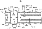
次に、本発明の第3実施形態を図4を用いて説明する。図4は本発明の第3実施形態を示す断熱ユニットの要部断面説明図である。
In addition, the vacuum heat insulating material 103 is covered with an elastic covering material 102 and stored in the outer bag 101, and the bag 101 is sealed in a state where the inside of the outer bag 101 is decompressed and the covering material 102 is compressed. 100, and the insulating material 100 is installed between the outer wall 201 and the inner wall 202, and the covering material 102 is restored by releasing the sealing of the outer bag 101 of the insulating material 100 so that the insulating material 100 is connected to the outer wall 201. The heat insulating wall is formed between the inner wall 202 and the heat insulating material 100, the outer wall 201, and the inner wall 202 to form a heat insulating wall. Is easy.
(Third embodiment)
Next, a third embodiment of the present invention will be described with reference to FIG. FIG. 4 is a cross-sectional explanatory view of a main part of a heat insulating unit showing a third embodiment of the present invention.

図4において、210は、冷蔵庫や冷凍庫、或いは、住宅や倉庫、冷凍車や車輌等を構成する断熱部分に設置できるように構成された断熱ユニットである。断熱ユニット210は、外壁211と内壁212との間に、一個或いは複数個の後述する断熱材110を設置して、外壁211と内壁212間の熱漏洩を減少できるように構成してある。なお、外壁211や内壁212は、冷蔵庫等を構成する外箱や内箱と兼用しても良く、或いは、住宅、車輌等の外郭材や内装材と兼用しても良い。   In FIG. 4, reference numeral 210 denotes a heat insulating unit configured to be installed in a heat insulating portion constituting a refrigerator, a freezer, a house, a warehouse, a freezer car, a vehicle, or the like. The heat insulating unit 210 is configured to reduce heat leakage between the outer wall 211 and the inner wall 212 by installing one or a plurality of heat insulating materials 110 described later between the outer wall 211 and the inner wall 212. The outer wall 211 and the inner wall 212 may also be used as an outer box or an inner box constituting a refrigerator or the like, or may be used as an outer material or an interior material for a house or a vehicle.

断熱材110は、真空断熱材113と、真空断熱材113を覆い、それ自身に可撓性と復元性を有しこの復元性により、断熱材110と、外壁211或いは内壁212とが互いに圧着するように構成された被覆材112と、真空断熱材113と被覆材112との間に設けられた、耐突き刺し強度を有する補強部材114とで構成してある。   The heat insulating material 110 covers the vacuum heat insulating material 113 and the vacuum heat insulating material 113, and has its own flexibility and resilience. With this resilience, the heat insulating material 110 and the outer wall 211 or the inner wall 212 are pressure-bonded to each other. And a reinforcing member 114 having a puncture resistance provided between the vacuum heat insulating material 113 and the covering material 112.

この補強部材114は、外壁211に部材213を固定する釘等214が誤って214bに示す位置に打たれても、或いは、内壁212に部材217を固定する螺子等218が誤って218bに示す位置にねじ込まれても、釘等214bや螺子等218bにより真空断熱材113が損傷を受け難いように、真空断熱材113をカバーできるように設置されている。なお、補強部材114は、前述した釘等214bや螺子等218bに対する耐突き刺し強度を保持すれば、その材料としては特に限定されるものではない。例えば、鋼板やアルミニウム板或いはABS樹脂等を主体にした強化合成樹脂等が使用可能である。   This reinforcing member 114 has a position where a nail or the like 214 for fixing the member 213 to the outer wall 211 is accidentally hit at a position indicated by 214b, or a screw or the like 218 for fixing the member 217 to the inner wall 212 is indicated by an error 218b. It is installed so that the vacuum heat insulating material 113 can be covered so that the vacuum heat insulating material 113 is not easily damaged by the nail 214b and the screw 218b. The material of the reinforcing member 114 is not particularly limited as long as it retains the piercing strength against the above-described nail 214b and screw 218b. For example, a reinforced synthetic resin mainly composed of a steel plate, an aluminum plate, an ABS resin, or the like can be used.

外袋111は、被覆材112を外壁211と内壁212に装着するときに、装着時のハンドリングにより、被覆材112の破片や粉末が周りに飛散しないように、被覆材112を覆うフィルム状の袋である。   The outer bag 111 is a film-like bag that covers the covering material 112 so that when the covering material 112 is attached to the outer wall 211 and the inner wall 212, the debris and powder of the covering material 112 are not scattered around by handling during attachment. It is.

この第3実施形態によれば、万一、螺子218や釘214b等が断熱材110中に、打ち込まれても、断熱材110中の真空断熱材113が損傷し難いので、断熱材110の設置場所が制限されない、且つ、長期間断熱性能の良好な断熱ユニットを提供できる。
(第4実施形態)
次に、本発明の第4実施形態を図5を用いて説明する。図5は本発明の第4実施形態を示す断熱ユニットの要部断面説明図である。
According to the third embodiment, even if the screw 218, the nail 214b, etc. are driven into the heat insulating material 110, the vacuum heat insulating material 113 in the heat insulating material 110 is not easily damaged. It is possible to provide a heat insulating unit that is not limited in location and has a good long-term heat insulating performance.
(Fourth embodiment)
Next, a fourth embodiment of the present invention will be described with reference to FIG. FIG. 5 is a cross-sectional explanatory view of a main part of a heat insulating unit showing a fourth embodiment of the present invention.

図5において、230は、冷蔵庫や冷凍庫、或いは、住宅や倉庫、冷凍車や車輌等を構成する断熱部分に設置できるように構成された断熱ユニットである。断熱ユニット230は、外壁231と内壁232との間を複数の断熱層に分割する仕切シート233、234を有しており、仕切シート233と234との間には断熱材100を、当初の厚さT11より小さい所定の厚さT53に圧縮して複数個設置し、複数個の断熱材100間には、充填材203を充填してある。   In FIG. 5, reference numeral 230 denotes a heat insulating unit configured to be installed in a heat insulating portion constituting a refrigerator, a freezer, a house, a warehouse, a freezer car, a vehicle, or the like. The heat insulation unit 230 includes partition sheets 233 and 234 that divide the space between the outer wall 231 and the inner wall 232 into a plurality of heat insulation layers. The heat insulation material 100 is placed between the partition sheets 233 and 234 at the initial thickness. A plurality of compressed members are set to a predetermined thickness T53 smaller than the thickness T11, and a filler 203 is filled between the plurality of heat insulating materials 100.

また、外壁231と仕切シート233との間には、真空断熱材173と真空断熱材173を覆い、それ自身に弾性を有する被覆材172と、真空断熱材173の外壁231側に設けられた、耐突き刺し強度を有する補強部材174とで構成してなる断熱材170を複数個設置し、複数個の断熱材170間には、充填材203を充填してある。   Further, between the outer wall 231 and the partition sheet 233, the vacuum heat insulating material 173 and the vacuum heat insulating material 173 are covered, and the covering material 172 having elasticity in itself is provided on the outer wall 231 side of the vacuum heat insulating material 173. A plurality of heat insulating materials 170 composed of reinforcing members 174 having puncture resistance are provided, and a filler 203 is filled between the plurality of heat insulating materials 170.

また、内壁232と仕切シート234との間には、真空断熱材183と、真空断熱材183を覆い、それ自身に可撓性と復元性を有する被覆材182と、真空断熱材183の内壁232側に設けられた、耐突き刺し強度を有する補強部材184とで構成してなる断熱材180を複数個設置し、複数個の断熱材180間には、充填材203を充填してある。   Further, between the inner wall 232 and the partition sheet 234, the vacuum heat insulating material 183, the covering material 182 that covers the vacuum heat insulating material 183 and has flexibility and resilience to itself, and the inner wall 232 of the vacuum heat insulating material 183 are provided. A plurality of heat insulating materials 180 formed by reinforcing members 184 having puncture strength provided on the side are provided, and a filler 203 is filled between the plurality of heat insulating materials 180.

なお、断熱材100、170、180の設置位置は、図5に示すように、真空断熱材103、173、183の設置部分を互いにずらすことにより、外壁231と内壁232との間の熱漏洩量が、いずれの部分においてもほぼ均一と成るように配置してある。すなわち、複数の断熱材170、100、180等の夫々の隙間に充填された充填材203は、図2にて前述したように、例えば、発泡ポリウレタンやホットメルト接着材であるため、その断熱性能は通常、上述した真空断熱材173、103、183等より劣る。従って、断熱性能の劣る充填材203部分の位置が互いにずれるように構成して、外壁231と内壁232との間の断熱性能が、いずれの部分においてもほぼ均一と成るように配置してある。   As shown in FIG. 5, the installation positions of the heat insulating materials 100, 170, and 180 are the amount of heat leakage between the outer wall 231 and the inner wall 232 by shifting the installation portions of the vacuum heat insulating materials 103, 173, and 183. However, they are arranged so as to be almost uniform in any part. That is, the filler 203 filled in the gaps of the plurality of heat insulating materials 170, 100, 180, etc. is, for example, foamed polyurethane or hot melt adhesive as described above with reference to FIG. Is usually inferior to the vacuum heat insulating materials 173, 103, 183, etc. described above. Accordingly, the positions of the portions of the filler 203 having inferior heat insulation performance are shifted from each other, and the heat insulation performance between the outer wall 231 and the inner wall 232 is arranged to be substantially uniform in any portion.

また、外壁231や内壁232は、冷蔵庫等を構成する外箱や内箱と兼用しても良く、或いは、住宅、車輌等の外郭材や内装材と兼用しても良い。   Further, the outer wall 231 and the inner wall 232 may also be used as an outer box or an inner box constituting a refrigerator or the like, or may be used as an outer material or an interior material for a house, a vehicle, or the like.

この第4実施形態によれば、外壁231と内壁232との間の断熱性能が、いずれの部分においてもほぼ均一と成るように構成できるので、温度差のある断熱壁においても、局部的な結露が生じない、断熱性能の良好な断熱ユニットを提供できる。   According to the fourth embodiment, since the heat insulating performance between the outer wall 231 and the inner wall 232 can be configured to be almost uniform in any part, even in a heat insulating wall having a temperature difference, local condensation is caused. It is possible to provide a heat insulating unit with good heat insulating performance.

また、外壁231と内壁232間の厚さ寸法(図5に示すT50寸法)が異なる断熱壁においても、外壁231と内壁232間を任意の数の複数層に分割し、この層内に、予め標準化された所定の大きさの断熱材100や170或いは180を使用すれば良いので、製造コスト上有利な、且つ、均一な断熱性能を有する断熱ユニットを提供できる。   Further, even in a heat insulating wall having a different thickness dimension (T50 dimension shown in FIG. 5) between the outer wall 231 and the inner wall 232, the outer wall 231 and the inner wall 232 are divided into an arbitrary number of layers, Since the standardized heat insulating material 100, 170, or 180 having a predetermined size may be used, it is possible to provide a heat insulating unit that is advantageous in terms of manufacturing cost and has uniform heat insulating performance.

また、複数の断熱層に分割する仕切シート233、234を、例えば、アルミニウム等の熱反射性を有する材料にて構成すれば、断熱ユニットの断熱性能を更に向上することもできる。   Moreover, if the partition sheets 233 and 234 divided into a plurality of heat insulation layers are made of a material having heat reflectivity such as aluminum, the heat insulation performance of the heat insulation unit can be further improved.

また、複数の断熱層に分割する仕切シート233、234の厚さT52、T54寸法を所定の大きさに設定すると共に、仕切シート233、234を、例えば、ブチルゴムやグラスウール等の遮音性や吸音性を有する材料にて構成すれば、断熱ユニットの防音性能を更に向上することもできる。
(第5実施形態)
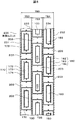
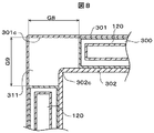
次に、本発明の第5実施形態を、図6から図9を用いて説明する。図6は本発明の第5実施形態を示す冷蔵庫の要部断面説明図、図7は図6におけるA−A断面図、図8は図6におけるB−B断面図、図9は図6におけるC部仕切りの要部拡大断面図を示す。
In addition, the thicknesses T52 and T54 of the partition sheets 233 and 234 to be divided into a plurality of heat insulating layers are set to predetermined sizes, and the partition sheets 233 and 234 are made to have sound insulation properties and sound absorption properties such as butyl rubber and glass wool, for example. If it comprises with the material which has, the sound insulation performance of a heat insulation unit can also be improved further.
(Fifth embodiment)
Next, a fifth embodiment of the present invention will be described with reference to FIGS. FIG. 6 is a cross-sectional explanatory diagram of a main part of a refrigerator showing a fifth embodiment of the present invention, FIG. 7 is a cross-sectional view along AA in FIG. 6, FIG. 8 is a cross-sectional view along BB in FIG. The principal part expanded sectional view of a C section partition is shown.

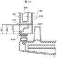
図6において、300は冷蔵庫の扉を含む断熱箱体である。断熱箱体300は、その外郭を成す外箱301と、内装側を形成する内箱302と、外箱301と内箱302間の断熱部分に設置された後述する真空断熱材を内包する複数の断熱材120(後述する断熱材120a、120b、120c、120d、120eのすべてを含めて説明する場合は、以下断熱材120と表示する)及び複数の断熱材120間に充填された後述する充填材311とにより構成されている。   In FIG. 6, reference numeral 300 denotes a heat insulating box including a refrigerator door. The heat insulating box 300 includes a plurality of outer casings 301 that form the outer shell, an inner box 302 that forms the interior side, and a vacuum insulating material that will be described later installed in a heat insulating portion between the outer box 301 and the inner box 302. A heat insulating material 120 (hereinafter described as the heat insulating material 120 when described including all of the heat insulating materials 120a, 120b, 120c, 120d, and 120e described later) and a filler described later filled between the plurality of heat insulating materials 120. 311.

そして、断熱部分体積の70%以上を無機物質とすることにより、断熱箱体300が廃棄されたときにも、自然界の生態系循環サイクルに対する負荷が小さく成るように構成してある。   And by making 70% or more of heat insulation part volume into an inorganic substance, even when the heat insulation box 300 is discarded, it has comprised so that the load with respect to the natural ecosystem circulation cycle may become small.

また、断熱箱体300内には、冷蔵室303aや野菜室303bで構成する冷蔵温度室303と、製氷室304aや冷凍室304bで構成する冷凍温度室304とが区画形成されている。305は冷蔵温度室303を冷却するように構成された冷蔵室冷却用ダクトである。306は、冷却器308や送風機307を内蔵し、且つ、冷凍温度室304を冷却できるように構成された冷凍室冷却用ダクトである。   In the heat insulation box 300, a refrigeration temperature chamber 303 configured by a refrigeration chamber 303a and a vegetable chamber 303b and a refrigeration temperature chamber 304 configured by an ice making chamber 304a and a freezing chamber 304b are partitioned. Reference numeral 305 denotes a refrigerating room cooling duct configured to cool the refrigerating temperature room 303. A freezer compartment cooling duct 306 includes a cooler 308 and a blower 307 and is configured to cool the freezing temperature chamber 304.

そして、冷蔵温度室303や冷凍温度室304等の熱漏洩を小さくするために、後述する真空断熱材を内包した複数の断熱材120を、冷蔵温度室303や冷凍温度室304等の周囲の断熱壁として設置してある。例えば、冷蔵温度室303を形成する壁面には、厚さT31寸法を有する複数の断熱材120aを設置し、冷蔵温度室303より低温度となる冷蔵室冷却用ダクト305背面には、断熱材120aのT31寸法より厚さの厚いT32寸法を有する断熱材120bを設置してある。また、冷蔵温度室303より低温度となる冷凍温度室304を形成する壁面には、断熱材120aのT31寸法より厚さの厚いT41寸法を有する複数の断熱材120cを設置し、冷凍温度室304より低温度となる冷凍室冷却用ダクト306背面には、断熱材120cのT41寸法より厚さの厚いT42寸法を有する断熱材120dを設置してある。また、冷凍温度室304下部の機械室内に設置された、圧縮機309や凝縮器310の周辺部は、その温度が通常の外気温度より高温度になるので、圧縮機309や凝縮器310の周辺部には、断熱材120cのT41寸法より厚さの厚いT43寸法を有する断熱材120eを設置してある。   In order to reduce heat leakage in the refrigeration temperature chamber 303 and the freezing temperature chamber 304, a plurality of heat insulating materials 120 including a vacuum heat insulating material, which will be described later, are insulated from the surroundings of the refrigeration temperature chamber 303, the freezing temperature chamber 304, and the like. It is installed as a wall. For example, a plurality of heat insulating materials 120a having a thickness T31 are installed on the wall surface forming the refrigeration temperature chamber 303, and the heat insulation material 120a is provided on the back surface of the refrigeration chamber cooling duct 305, which has a lower temperature than the refrigeration temperature chamber 303. A heat insulating material 120b having a T32 dimension that is thicker than the T31 dimension is installed. In addition, a plurality of heat insulating materials 120c having a T41 size thicker than the T31 size of the heat insulating material 120a are installed on the wall surface forming the refrigerating temperature chamber 304 that is lower in temperature than the refrigerated temperature chamber 303. A heat insulating material 120d having a T42 dimension that is thicker than the T41 dimension of the heat insulating material 120c is installed on the back surface of the cooling chamber cooling duct 306 that is at a lower temperature. Moreover, since the temperature of the peripheral part of the compressor 309 and the condenser 310 installed in the machine room below the refrigeration temperature chamber 304 is higher than the normal outside air temperature, the peripheral part of the compressor 309 and the condenser 310 is The part is provided with a heat insulating material 120e having a T43 dimension that is thicker than the T41 dimension of the heat insulating material 120c.

以上の例のように、外箱301と内箱302との間の断熱部分は、断熱部分の熱漏洩量をできるだけ低減するために、その体積のできるだけ多くの部分に断熱材120を使用するように設定してある。   As in the above example, the heat insulating part between the outer box 301 and the inner box 302 uses the heat insulating material 120 in as much part of its volume as possible in order to reduce the heat leakage amount of the heat insulating part as much as possible. It is set to.

しかし、断熱材120自身の強度は、硬質ウレタンフォーム等より劣るものであるため、断熱材120のみで外箱301と内箱302との間の断熱部分を構成すると、断熱箱体300自身の強度が不足して、実使用に耐えない恐れが生じる。   However, since the strength of the heat insulating material 120 itself is inferior to that of rigid urethane foam or the like, if the heat insulating portion between the outer box 301 and the inner box 302 is constituted only by the heat insulating material 120, the strength of the heat insulating box body 300 itself. There is a risk that it will not be able to endure actual use.

そこで、この第5実施形態においては、断熱箱体300の強度向上を必要とする所に、外箱301や内箱302や断熱材120との接着力を有する、例えば硬質ウレタンフォーム等の充填材311を充填して、断熱箱体300の強度を実用上問題の無いように構成してある。具体的には、図6に示す箱体開口周縁部(図6や図7のG1部)や、箱体稜線部(図6のG2、G3部や図7のG6、G7部及び図8に示すG8、G9部)や、複数の断熱材120間(図6のG4部)等に、それ自身が接着力と断熱性を有する硬質ウレタンフォーム等の充填材311を発泡充填して、該部の強度向上を図ることにより、断熱箱体300の強度を実用上問題の無いようにしてある。   Therefore, in the fifth embodiment, a filler having an adhesive force with the outer box 301, the inner box 302, and the heat insulating material 120, for example, a hard urethane foam, is required where the strength of the heat insulating box 300 needs to be improved. 311 is filled so that the strength of the heat insulating box 300 is not problematic in practice. Specifically, the box opening peripheral portion shown in FIG. 6 (G1 portion in FIGS. 6 and 7), the box ridge line portion (G2 and G3 portions in FIG. 6, G6 and G7 portions in FIG. 7 and FIG. 8). G8, G9 part) or between the plurality of heat insulating materials 120 (G4 part in FIG. 6), etc., by filling with foaming filler 311 such as a hard urethane foam which itself has adhesive strength and heat insulating properties. The strength of the heat insulating box 300 is made practically unproblematic by improving the strength.

なお、発明者らの実験によれば、断熱箱体300の強度を実用上問題の無いようにする為には、断熱箱体300の強度向上となる所、例えば、前述した箱体開口周縁部や箱体稜線部或いは複数の断熱材120間等に、それ自身が接着力を有する充填材311を、前記断熱部分体積の約20%以上設置する必要があり、望ましくは約25%以上設置することが良いことが判った。   According to experiments by the inventors, in order to make the strength of the heat insulation box 300 practically unproblematic, the place where the strength of the heat insulation box 300 is improved, for example, the aforementioned box opening peripheral portion. In addition, it is necessary to install the filler 311 having an adhesive force between itself and the box ridge line portion or between the plurality of heat insulating materials 120 by about 20% or more, preferably about 25% or more of the heat insulating portion volume. It turns out that it is good.

また、断熱箱体300の強度向上となるように充填する充填材311は、現時点においては、硬質ウレタンフォーム等を発泡充填する方法がその生産性やコストの面で良いことも判った。しかし、硬質ウレタンフォーム等の有機物質は、この物質を廃棄した場合には、地球環境の生態系の循環サイクルに負荷となり、かつ、硬質ウレタンフォーム等の有機物は、このまま使用し続けると将来枯渇する恐れのある石油等から生成されているので、その使用量をできるだけ少なくする必要がある。   It has also been found that the filling material 311 to be filled so as to improve the strength of the heat insulating box 300 is, at present, a method of foaming and filling hard urethane foam or the like in terms of productivity and cost. However, if organic substances such as rigid urethane foam are discarded, they will be a burden on the circulation cycle of the ecosystem of the global environment, and organic substances such as rigid urethane foam will be depleted in the future if they are used as they are. Since it is generated from petroleum that has a fear, it is necessary to reduce the amount of use as much as possible.

そこで、上述した断熱箱体300の強度を実用上問題の無いようにすると共に、有機物からなる物質をできるだけ少なくするために、この第5実施形態においては、充填材311以外の断熱部分を、できるだけ無機物とするように構成した。そして、発明者らの実験によれば、充填材311以外の断熱部分、つまり、前述した複数の断熱材120は、後述するように、その体積のほぼ97%程度以上を無機物質とすることができた。従って、断熱箱体300の断熱部分体積に占める無機物の割合は、{(100−25(充填材の体積))×0.97(断熱材の無機物割合)=72.7}となる、つまり、約72%以上とすることができた。   Therefore, in order to make the strength of the above-described heat insulating box 300 practically unproblematic and to reduce the number of organic substances as much as possible, in the fifth embodiment, heat insulating portions other than the filler 311 are provided as much as possible. An inorganic material was used. According to the experiments by the inventors, the heat insulating portion other than the filler 311, that is, the plurality of heat insulating materials 120 described above, has about 97% or more of its volume as an inorganic substance, as will be described later. did it. Therefore, the ratio of the inorganic substance to the heat insulation partial volume of the heat insulation box 300 is {(100-25 (volume of filler)) × 0.97 (inorganic substance ratio of heat insulation) = 72.7}. It could be about 72% or more.

以下、上述した断熱部分体積の70%以上を無機物質とした例について説明する。なお、断熱材120の体積に占める無機物質の割合は、断熱材120を設置する断熱箱体300自身の大きさにより変化するので、説明の簡略のために、図6に示す冷蔵庫の大きさを、2005年度にて一般的に市販されている400リットルクラスと同程度と仮定した。また、その断熱壁厚さを表2に示す寸法と仮定した。   Hereinafter, an example in which 70% or more of the above-described heat insulating partial volume is an inorganic substance will be described. In addition, since the ratio of the inorganic substance to the volume of the heat insulating material 120 varies depending on the size of the heat insulating box 300 itself in which the heat insulating material 120 is installed, the size of the refrigerator shown in FIG. In 2005, it was assumed to be the same level as the 400 liter class that is generally commercially available. The heat insulating wall thickness was assumed to be the dimensions shown in Table 2.

ここで、表1及び表2について説明する。   Here, Table 1 and Table 2 will be described.

Figure 2007113748
Figure 2007113748

Figure 2007113748
Figure 2007113748

表1において、「図中の記号」欄は前述した図6から図8に示す記号であり、「大きさ」欄は上述した400リットルクラス冷蔵庫の寸法例を示す。なお、「大きさ」欄の充填材寸法G1、G2、G3・・・G9の数値は、発明者らの実験により、上述した断熱箱体300の強度を実用上問題の無いようした時の具体例である。   In Table 1, the “symbol in the drawing” column is the symbol shown in FIGS. 6 to 8 described above, and the “size” column shows a dimension example of the 400 liter class refrigerator described above. In addition, the numerical values of the filler dimensions G1, G2, G3... G9 in the “size” column are specific values obtained when the above-described strength of the heat insulating box 300 is not practically problematic by the inventors' experiments. It is an example.

表2において、「庫内温度」とは各部位の室内やダクト内の設定温度であり、「外気温度」とは冷蔵庫各部位の周囲温度であり、「温度差」とは「庫内温度」と「外気温度」との温度差を示す。「断熱材厚さ」とは各部位の断熱材120の厚さ寸法例であり、「真空断熱材厚さ」とは断熱材120中に内包された真空断熱材の厚さ例を示す。そして、この例においては、断熱壁からの熱漏洩量をいずれの部位においても均一に低減できるように、断熱性能の優れた真空断熱材の厚さを、真空断熱材が設置される部位の「温度差」にほぼ比例するように構成した。例えば、「温度差」22℃の冷蔵温度室周囲に設置する断熱材120a(図6の120a)の厚さT31寸法中に内包する真空断熱材の厚さt31を20mmとした場合、「温度差」45℃の冷凍温度室周囲に設置する断熱材120c(図6の120c)の厚さT41寸法中に内包する真空断熱材の厚さt41を約40mm{t41=(45/22)×t31}とし、「温度差」60℃の冷凍室冷却ダクト背面に設置する断熱材120d(図6の120d)の厚さT42寸法中に内包する真空断熱材の厚さt42を約60mm{t42=(60/22)×t31}として、各部位での熱漏洩量を均一に低減できるように構成した。   In Table 2, “inside temperature” is a set temperature in the room or duct of each part, “outside air temperature” is an ambient temperature in each part of the refrigerator, and “temperature difference” is “inside temperature”. And the temperature difference between “outside air temperature”. “Insulating material thickness” is an example of the thickness dimension of the insulating material 120 at each part, and “vacuum insulating material thickness” indicates an example of the thickness of the vacuum insulating material contained in the insulating material 120. In this example, the thickness of the vacuum heat insulating material having excellent heat insulating performance is reduced so that the amount of heat leakage from the heat insulating wall can be uniformly reduced in any portion. The temperature difference is substantially proportional to the temperature difference. For example, when the thickness t31 of the vacuum heat insulating material included in the thickness T31 of the heat insulating material 120a (120a in FIG. 6) installed around the refrigerated temperature chamber of 22 ° C. is 20 mm, The thickness t41 of the vacuum heat insulating material contained in the thickness T41 of the heat insulating material 120c (120c in FIG. 6) installed around the freezing temperature chamber of 45 ° C. is about 40 mm {t41 = (45/22) × t31} The thickness t42 of the vacuum heat insulating material included in the thickness T42 of the heat insulating material 120d (120d in FIG. 6) installed on the rear surface of the freezer compartment cooling duct having a “temperature difference” of 60 ° C. is about 60 mm {t42 = (60 / 22) × t31} so that the amount of heat leakage at each part can be reduced uniformly.

そして、断熱材120中に内包する真空断熱材123を、グラスウール等の無機繊維から成る芯材123fと、芯材123fを覆う外被材123eとから構成し、外被材123eを、例えば、ポリエチレンテレフタレート樹脂等の有機物質から成る50μmから200μmのフィルムにて形成すると共に、真空断熱材123中の水分やガス成分を吸着する不図示のゲッター剤を、例えば、モレキュラーシーブスやドーソナイト等の有機物質として、芯材123fの体積のほぼ1%程度に設定し、真空断熱材123の大きさを、前述した表1、2の寸法にすると、真空断熱材123は、そのほぼ98%程度を無機物質により構成することができた。   And the vacuum heat insulating material 123 included in the heat insulating material 120 is comprised from the core material 123f which consists of inorganic fibers, such as glass wool, and the jacket material 123e which covers the core material 123f, and the jacket material 123e is polyethylene, for example A getter agent (not shown) that forms a film of 50 μm to 200 μm made of an organic material such as terephthalate resin and adsorbs moisture and gas components in the vacuum heat insulating material 123 is used as an organic material such as molecular sieves or dawsonite. When the volume of the core material 123f is set to about 1% and the size of the vacuum heat insulating material 123 is set to the dimensions shown in Tables 1 and 2, the vacuum heat insulating material 123 has about 98% of the inorganic material. Could be configured.

そして、真空断熱材123を覆う被覆材122を、グラスウール等の無機繊維にて形成し、被覆材122を覆う外袋121を、例えば、ポリエチレン樹脂等の有機物質から成る50μmから200μmのフィルムにて形成し、断熱材120の大きさを、前述した表1、2の寸法にすると、断熱材120は、そのほぼ97%程度を無機物質により構成することができた。   Then, a covering material 122 that covers the vacuum heat insulating material 123 is formed of inorganic fibers such as glass wool, and an outer bag 121 that covers the covering material 122 is formed with a film of 50 μm to 200 μm made of an organic substance such as polyethylene resin, for example. When formed and the size of the heat insulating material 120 is set to the dimensions shown in Tables 1 and 2, the heat insulating material 120 was able to be composed of approximately 97% of an inorganic substance.

そして、断熱材120を図6に示すように設置し、断熱材120や充填材311の寸法を、前述した表1、2の寸法に設定すると、前記断熱部分の体積のほぼ70%以上を無機物質にすることができた。   Then, when the heat insulating material 120 is installed as shown in FIG. 6 and the dimensions of the heat insulating material 120 and the filler 311 are set to the dimensions shown in Tables 1 and 2, the above-described heat insulating portion has a volume of almost 70% or more of inorganic. I was able to make it into a substance.

図7において、307は断熱箱体300の庫内側を形成する内箱背面部302aに設けられた凸部302bに設置された送風機である。120dは送風機307取り付け部の背面に設置された断熱材である。そして、送風機307の、螺子等の係止具307a先端が、断熱材120dを傷つけることの無いように、係止具307a先端と断熱材120dとの間隙δ1を確保できるように、凸部302bの凸部寸法H37を設定してある。312は箱体開口周縁部(G1)の強度を向上すると共に、該部に設置する断熱材120の位置を決めるための、位置決め兼補強部材であり、例えば、所定の強度を有する合成樹脂や鋼板等により形成されている。   In FIG. 7, reference numeral 307 denotes a blower installed on the convex portion 302 b provided on the inner box back surface portion 302 a that forms the inside of the heat insulating box 300. 120d is a heat insulating material installed on the back surface of the fan 307 mounting portion. Then, in order to ensure a gap δ1 between the front end of the locking tool 307a and the heat insulating material 120d so that the front end of the locking tool 307a such as a screw of the blower 307 does not damage the heat insulating material 120d, the protrusion 302b A convex dimension H37 is set. Reference numeral 312 denotes a positioning / reinforcing member for improving the strength of the peripheral edge (G1) of the box body and determining the position of the heat insulating material 120 to be installed in the portion. For example, a synthetic resin or steel plate having a predetermined strength Etc. are formed.

なお、位置決め兼補強部材312を設置した場合は、位置決め兼補強部材312の補強強度程度により、断熱箱体300の箱体強度が向上するので、該部に充填する充填材311の充填寸法G1は、表1にて前述した寸法より小さく設定できる事は自明である。   When the positioning / reinforcing member 312 is installed, the box strength of the heat insulating box 300 is improved depending on the reinforcing strength of the positioning / reinforcing member 312. Therefore, the filling dimension G1 of the filler 311 filled in the portion is Obviously, it can be set smaller than the dimensions described above in Table 1.

W32寸法は冷蔵温度室303や冷凍温度室304の庫内幅寸法を示し、W33寸法は冷蔵温度室303や冷凍温度室304の扉に配設された断熱材120中の真空断熱材123の幅寸法を示す。そして、真空断熱材123の幅寸法W33を、庫内幅寸法W32より大きく設定することにより、スロート部S31よりの熱漏洩量を低減するように構成してある。換言すれば、冷蔵庫のスロート部S31よりの熱漏洩量を低減できるように、外気温度より低温度となる庫内面302eをδ2寸法(δ2>零)だけオーバーハングできるように、真空断熱材123の幅寸法W33を設定してある。   The dimension W32 indicates the internal width dimension of the refrigeration temperature chamber 303 or the freezing temperature chamber 304, and the dimension W33 indicates the width of the vacuum heat insulating material 123 in the heat insulating material 120 disposed at the door of the refrigeration temperature chamber 303 or the freezing temperature chamber 304. Show dimensions. And it is comprised so that the amount of heat leaks from throat part S31 may be reduced by setting the width dimension W33 of the vacuum heat insulating material 123 larger than the interior width dimension W32. In other words, in order to reduce the amount of heat leakage from the throat portion S31 of the refrigerator, the vacuum heat insulating material 123 can be overhanged by the dimension δ2 (δ2> zero) on the inner surface 302e having a temperature lower than the outside air temperature. A width dimension W33 is set.

図8において、311は、断熱性と接着性を有し、それ自身にある程度の強度を有する、例えば、硬質ウレタンフォーム等の充填材であり、充填材311自身が有する接着力により、内箱稜線部302cと、外箱稜線部301cと、複数の断熱材120とを一体的に接着するように形成されている。換言すれば、断熱箱体300の強度を実用上問題の無い強度にする為に、断熱箱体300の強度上のポイントとなる稜線部に、接着力を有する充填材311を充填してある。   In FIG. 8, reference numeral 311 denotes a filler such as a hard urethane foam having heat insulation and adhesiveness and having a certain degree of strength, and the inner box ridge line is formed by the adhesive force of the filler 311 itself. The portion 302c, the outer box ridgeline portion 301c, and the plurality of heat insulating materials 120 are integrally bonded. In other words, in order to make the strength of the heat insulating box 300 have no problem in practical use, the filler 311 having adhesive force is filled in the ridge line portion that is a point on the strength of the heat insulating box 300.

なお、充填材311を充填する部分(図8のG8、G9部)の大きさは、断熱箱体300の大きさや外箱301自身の強度程度、或いは、内箱302自身の強度程度により設定することは自明である。   The size of the portion (G8, G9 in FIG. 8) filled with the filler 311 is set according to the size of the heat insulating box 300, the strength of the outer box 301 itself, or the strength of the inner box 302 itself. That is obvious.

図9において、500は図6における冷蔵温度室303と冷凍温度室304とを区画形成する中仕切である。400は、中仕切500と一体或いは別体に形成され、図6における野菜室扉や製氷室扉との閉塞面板401や温熱パイプ402を有する前仕切である。600は、中仕切500と一体或いは別体に形成され、冷蔵温度室303と冷凍室冷却用ダクト306とを区画形成する後仕切である。   In FIG. 9, reference numeral 500 denotes a partition that partitions the refrigeration temperature chamber 303 and the freezing temperature chamber 304 in FIG. Reference numeral 400 denotes a front partition which is formed integrally with or separately from the middle partition 500 and has a closed face plate 401 and a heat pipe 402 for the vegetable room door and ice making room door in FIG. Reference numeral 600 denotes a rear partition that is formed integrally with or separately from the inner partition 500 and that partitions the refrigeration temperature chamber 303 and the freezer compartment cooling duct 306.

そして、仕切400、500、600は、いずれも、温度差を有する室を仕切るように構成されているので、その表面側或いは裏面側に結露や結霜を生じないように断熱する必要がある。また、仕切400、500、600はいずれも庫内に設置されているので、その占める体積分により、冷蔵庫に貯蔵する貯蔵食品の収納スペースをできるだけ犠牲にしないように薄型にする必要がある。   And since all the partitions 400, 500, 600 are comprised so that the chamber which has a temperature difference may be partitioned, it is necessary to insulate so that dew condensation and frost may not arise on the surface side or the back surface side. Moreover, since all of the partitions 400, 500, and 600 are installed in the cabinet, it is necessary to make them thin so as not to sacrifice as much as possible the storage space for the stored food stored in the refrigerator due to the volume of the partition.

そこで、この第5実施形態においては、仕切(400、500、600)内に、断熱性能の良好な後述する真空断熱材(143、153、163)を内包した断熱材(140、150、160)を設置して、仕切(400、500、600)の結露や結霜を防止すると共に、仕切、400、500、600を薄型にして、内容積効率の良い冷蔵庫を提供するものである。つまり、断熱性能の良好な真空断熱材(143、153、163)を、それ自身に可撓性と復元性を有する被覆材(142、152、162)、例えば、グラスウール等の無機繊維、にて覆うことにより、被覆材(142、152、162)自身の可撓性と復元性によって、仕切(400、500、600)内に隙間無く設置できるので、前述した仕切りの結露防止や仕切の薄型化ができるのである。   Therefore, in the fifth embodiment, heat insulating materials (140, 150, 160) in which vacuum heat insulating materials (143, 153, 163) described later having good heat insulating performance are included in the partitions (400, 500, 600). Is provided to prevent condensation and frost formation on the partitions (400, 500, 600), and to make the partitions, 400, 500, 600 thin so as to provide a refrigerator with high internal volume efficiency. That is, a vacuum heat insulating material (143, 153, 163) with good heat insulating performance is applied to a covering material (142, 152, 162) having flexibility and resilience in itself, for example, inorganic fibers such as glass wool. By covering, the covering material (142, 152, 162) itself can be installed in the partition (400, 500, 600) without any gaps due to the flexibility and resilience of the covering material (142, 152, 162). Can do it.

なお、真空断熱材を内包した被覆材(142、152、162)を外袋(141、151、161)で覆う構成にすれば、断熱材(140、150、160)を仕切(400、500、600)内に設置するときの設置作業時に、被覆材(142、152、162)の破片や微粉が周囲に散らばらないので、ハンドリング性の良好な断熱材(140、150、160)とすることができる。   In addition, if it is set as the structure which covers the coating | covering material (142,152,162) which included the vacuum heat insulating material with the outer bag (141,151,161), a heat insulating material (140,150,160) will be divided (400,500, 600) Since the debris and fine powder of the covering material (142, 152, 162) will not be scattered around during the installation work when installing in 600), the heat insulating material (140, 150, 160) with good handling properties should be used. Can do.

この第5実施形態によれば、冷蔵庫や冷凍庫、或いは、住宅や倉庫、冷凍車や車輌等を構成する断熱部分体積の70%以上を無機物質としたので、自然界の生態系循環サイクルに負荷となる有機物質が少ないので、地球環境にやさしい断熱材を備えた断熱ユニットを提供できる。   According to the fifth embodiment, since 70% or more of the heat insulating part volume constituting the refrigerator, freezer, house, warehouse, refrigerated vehicle, vehicle, or the like is made of an inorganic substance, it is a burden on the natural ecosystem circulation cycle. Since there are few organic substances, it is possible to provide a thermal insulation unit equipped with a thermal insulation material that is friendly to the global environment.

また、断熱部分体積の70%以上を占める部分に、断熱性能の良好な真空断熱材を内包した断熱材120を設置すると共に、断熱材120間及び断熱箱体300の強度向上となる要所に、それ自身が接着性を有する充填材311を設置したので、断熱性能の良好な、且つ、箱体強度的に実用上問題の生じない構造を提供できる。   Moreover, in the part which occupies 70% or more of a heat insulation part volume, while installing the heat insulating material 120 which included the vacuum heat insulating material with favorable heat insulating performance, it is a key point where the strength between the heat insulating materials 120 and the heat insulating box 300 is improved. Since the filler 311 having adhesiveness itself is installed, it is possible to provide a structure having good heat insulation performance and practically no problem in terms of box strength.

また、断熱材120の体積のほぼ97%程度以上を無機物質としているので、断熱材120が廃棄されたときにも、自然界の生態系循環サイクルに負荷となる有機物質が少ないので、地球環境にやさしい断熱材を提供できる。   In addition, since about 97% or more of the volume of the heat insulating material 120 is made of an inorganic material, even when the heat insulating material 120 is discarded, there are few organic materials that become a burden on the ecosystem circulation cycle in the natural world. We can provide easy insulation.

また、断熱部分体積の70%以上を占める部分に、断熱性能の良好な真空断熱材を内包した断熱材120を設置すると共に、冷蔵温度室と冷凍温度室を仕切る仕切(400、500、600)内に、断熱性能の良好な後述する真空断熱材(143、153、163)を内包した断熱材(140、150、160)を設置したので、内容積効率が良く、しかも、省エネ上有利な冷蔵庫を提供できる。
(第6実施形態)
次に、本発明の第6実施形態を、図10を用いて説明する。図10は本発明の第6実施形態を示す冷蔵庫の要部断面説明図である。この第6実施形態は、次に述べる点で第5実施形態と相違するものであり、その他の点については第5実施形態と基本的には同一であるので、重複する説明を省略する。
In addition, a heat insulating material 120 containing a vacuum heat insulating material with good heat insulating performance is installed in a portion occupying 70% or more of the heat insulating portion volume, and a partition (400, 500, 600) that partitions the refrigeration temperature chamber and the freezing temperature chamber Inside, the heat insulating materials (140, 150, 160) including the vacuum heat insulating materials (143, 153, 163), which will be described later, which have good heat insulating performance, are installed, so that the internal volume efficiency is good and the refrigerator is advantageous in terms of energy saving. Can provide.
(Sixth embodiment)
Next, a sixth embodiment of the present invention will be described with reference to FIG. FIG. 10 is a cross-sectional explanatory view of the main part of the refrigerator showing the sixth embodiment of the present invention. The sixth embodiment is different from the fifth embodiment in the points described below, and the other points are basically the same as those in the fifth embodiment, and thus redundant description is omitted.

図10において、G21部は、断熱箱体300の箱体強度が向上するように、接着性を有する充填材311を充填した箱体開口周縁部である。301f及び302fは、箱体開口周縁部の実用強度を補強するために、外箱301や内箱302と一体に延出形成された補強部である。換言すれば、内箱開口フランジ部周縁に立ち上げられた補強部302fの立ち上げ高さG23寸法、或いは、内箱開口フランジ部を挟着支持する外箱挟着部より延出された補強部310fの高さG22寸法を所定の大きさに設定することにより、断熱箱体300の箱体強度を実用上問題の生じないように構成したものである。   In FIG. 10, G21 part is a box-opening peripheral part filled with a filler 311 having adhesive properties so that the box strength of the heat insulating box 300 is improved. Reference numerals 301f and 302f denote reinforcing portions that are integrally formed with the outer box 301 and the inner box 302 in order to reinforce the practical strength of the peripheral edge of the box body opening. In other words, the height G23 of the reinforcing portion 302f raised at the periphery of the inner box opening flange portion, or the reinforcing portion extended from the outer box holding portion that holds the inner box opening flange portion. By setting the height G22 dimension of 310f to a predetermined size, the box strength of the heat insulating box 300 is configured so as not to cause a practical problem.

かかる第6実施形態によれば、外箱301や内箱302と一体に延出形成された補強部301f、302fを設けることにより、断熱箱体300の箱体強度を実用上問題の生じないように構成しているので、補強のための部材等が不要となるので、製造コスト上有利な断熱箱体を提供できる。   According to the sixth embodiment, by providing the reinforcing portions 301f and 302f that are integrally formed with the outer box 301 and the inner box 302, the box strength of the heat insulating box 300 does not cause a practical problem. Therefore, a reinforcing member or the like is not necessary, so that a heat insulating box that is advantageous in terms of manufacturing cost can be provided.

本発明の第1実施形態に係る断熱材の断面図である。It is sectional drawing of the heat insulating material which concerns on 1st Embodiment of this invention. 本発明の第2実施形態を示す断熱ユニットの要部断面説明図である。It is principal part sectional explanatory drawing of the heat insulation unit which shows 2nd Embodiment of this invention. 図2の断熱ユニットの製造方法の一例を説明する製造過程の断面図である。It is sectional drawing of the manufacture process explaining an example of the manufacturing method of the heat insulation unit of FIG. 本発明の第3実施形態を示す断熱ユニットの要部断面説明図である。It is principal part sectional explanatory drawing of the heat insulation unit which shows 3rd Embodiment of this invention. 本発明の第4実施形態を示す断熱ユニットの要部断面説明図である。It is principal part cross-sectional explanatory drawing of the heat insulation unit which shows 4th Embodiment of this invention. 本発明の第5実施形態を示す冷蔵庫の要部断面説明図である。It is principal part cross-sectional explanatory drawing of the refrigerator which shows 5th Embodiment of this invention. 図6におけるA−A断面図である。It is AA sectional drawing in FIG. 図6におけるB−B断面図である。It is BB sectional drawing in FIG. 図6におけるC部仕切りの要部拡大断面図である。It is a principal part expanded sectional view of the C section partition in FIG. 本発明の第6実施形態を示す冷蔵庫の要部断面説明図である。It is principal part sectional explanatory drawing of the refrigerator which shows 6th Embodiment of this invention. 従来例を示す真空断熱材の要部断面説明図である。It is principal part cross-sectional explanatory drawing of the vacuum heat insulating material which shows a prior art example.

符号の説明Explanation of symbols

100,110,120,120a,120b,120c,120d,120e,140,150,160,170,180,190…断熱材、101,111,121,141,151,161,171,181,191…外袋、102,112,122,142,152,162,172,182,192…被覆材、103,113,123,143,153,163,173,183,193…真空断熱材、103d,103e,123e…外被材、103f,123f…芯材、103g…耳部、114,174,194…補強部材、200、210、230…断熱ユニット、201,211,231,301…外壁、202,212,232,302…内壁、203,216,235,236,237,311,313…充填材、204…接着剤、213,217…部材、214,214b…釘等、218,218b…螺子等、233,234…仕切シート、300…断熱箱体、301…外箱、302…内箱、303…冷蔵温度室、304…冷凍温度室、305…冷蔵室冷却用ダクト、306…冷凍室冷却用ダクト、307…送風機、307a…係止具、308…冷却器、309…圧縮機、310…凝縮器、312…位置決め兼補強部材、400…前仕切、500…中仕切、600…後仕切。   100,110,120,120a, 120b, 120c, 120d, 120e, 140,150,160,170,180,190 ... insulation, 101,111,121,141,151,161,171,181,191 ... outside Bag, 102, 112, 122, 142, 152, 162, 172, 182, 192 ... Covering material, 103, 113, 123, 143, 153, 163, 173, 183, 193 ... Vacuum insulation, 103d, 103e, 123e ... Jacket material, 103f, 123f ... Core material, 103g ... Ear part, 114, 174, 194 ... Reinforcement member, 200, 210, 230 ... Thermal insulation unit, 201, 211, 231, 301 ... Outer wall, 202, 212, 232 , 302 ... inner wall, 203, 216, 235, 236, 237, 311, 313 ... filler, 2 4 ... Adhesive, 213, 217 ... Member, 214, 214b ... Nail, etc. 218, 218b ... Screw, etc. 233, 234 ... Partition sheet, 300 ... Insulation box, 301 ... Outer box, 302 ... Inner box, 303 ... Refrigeration temperature chamber, 304 ... Refrigeration temperature chamber, 305 ... Refrigeration chamber cooling duct, 306 ... Freezing chamber cooling duct, 307 ... Blower, 307a ... Locking tool, 308 ... Cooler, 309 ... Compressor, 310 ... Condenser 312 ... Positioning and reinforcing member, 400 ... Front partition, 500 ... Middle partition, 600 ... Rear partition.

Claims (10)

弾性を有する被覆材で真空断熱材を覆って外袋内に収納し、この外袋の内部を減圧すると共に前記被覆材を圧縮した状態で該外袋を密閉して断熱材を形成し、
この断熱材を外壁と内壁との間に設置すると共に該断熱材の外袋の密閉を解除することにより前記被覆材を復元させて前記断熱材を前記外壁と前記内壁との間に挟持させて、この断熱材と前記外壁と前記内壁とから断熱壁を形成する
ことを特徴とする断熱壁の製造方法。
Covering the vacuum heat insulating material with an elastic covering material and storing it in the outer bag, reducing the pressure inside the outer bag and sealing the outer bag with the covering material compressed to form a heat insulating material,
The heat insulating material is installed between the outer wall and the inner wall, and the covering material is restored by releasing the sealing of the outer bag of the heat insulating material so that the heat insulating material is sandwiched between the outer wall and the inner wall. A method for manufacturing a heat insulating wall, comprising forming a heat insulating wall from the heat insulating material, the outer wall, and the inner wall.
外壁と、内壁と、前記外壁と前記内壁との間に設置された断熱材と、からなる断熱ユニットであって、
前記断熱材は、真空断熱材と、この真空断熱材を覆うと共に弾性を有する被覆材と、前記真空断熱材を覆った前記被覆材を覆う外袋とを備えている
ことを特徴とする断熱ユニット。
A heat insulating unit comprising an outer wall, an inner wall, and a heat insulating material installed between the outer wall and the inner wall,
The heat insulating material includes a vacuum heat insulating material, a covering material that covers the vacuum heat insulating material and has elasticity, and an outer bag that covers the covering material that covers the vacuum heat insulating material. .
請求項2に記載の断熱ユニットにおいて、前記真空断熱材は、パネル状の芯材と、この芯材を包み且つこの芯材を含む内部を真空状態にした外被材とを備えてパネル状に形成され、前記被覆材は前記真空断熱材の平面部両側を覆うように設置されていることを特徴とする断熱ユニット。   3. The heat insulating unit according to claim 2, wherein the vacuum heat insulating material has a panel-shaped core material and a cover material that wraps the core material and has an inside including the core material in a vacuum state. The heat insulating unit is formed, and the covering material is installed so as to cover both sides of the flat portion of the vacuum heat insulating material. 請求項3に記載の断熱ユニットにおいて、前記被覆材及び前記外袋は前記真空断熱材の周囲に形成される耳部を含む大きさより幅広に形成されてこの耳部を覆っていることを特徴とする断熱ユニット。   The heat insulating unit according to claim 3, wherein the covering material and the outer bag are formed wider than a size including an ear portion formed around the vacuum heat insulating material to cover the ear portion. Heat insulation unit. 請求項4に記載の断熱ユニットにおいて、前記真空断熱材と前記被覆材との間に釘や螺子等に対する耐突き刺し強度を有する補強部材を設置したことを特徴とする断熱ユニット。   5. The heat insulating unit according to claim 4, wherein a reinforcing member having a puncture strength against a nail or a screw is installed between the vacuum heat insulating material and the covering material. 外壁と、内壁と、前記外壁と前記内壁との間に設置された断熱材とからなる断熱ユニットであって、
前記断熱材は、真空断熱材と、この真空断熱材を覆うと共に弾性を有する被覆材と、前記真空断熱材を覆った前記被覆材を覆う外袋とを備えて構成され、
前記被覆材は無機繊維あるいは有機繊維からなる繊維重合体で構成されており、
前記断熱材は前記被覆材の弾性により両側平面部を前記外壁及び前記内壁に当接するように設置されている
ことを特徴とする断熱ユニット。
A heat insulating unit comprising an outer wall, an inner wall, and a heat insulating material installed between the outer wall and the inner wall,
The heat insulating material includes a vacuum heat insulating material, a covering material that covers the vacuum heat insulating material and has elasticity, and an outer bag that covers the covering material that covers the vacuum heat insulating material,
The covering material is composed of a fiber polymer composed of inorganic fibers or organic fibers,
The heat insulating unit is installed so that both side flat portions are brought into contact with the outer wall and the inner wall by elasticity of the covering material.
請求項1から6の何れかに記載の断熱ユニットにおいて、前記被覆材はブチルゴムやグラスウール等の遮音性や吸音性を有する材料で形成したことを特徴とするた断熱ユニット。   The heat insulation unit according to any one of claims 1 to 6, wherein the covering material is formed of a material having sound insulation and sound absorption properties such as butyl rubber and glass wool. 真空断熱材と、該真空断熱材を覆うと共に弾性を有する被覆材と、前記真空断熱材を覆った前記被覆材を覆う外袋と、を有して構成したことを特徴とする断熱材。   A heat insulating material comprising a vacuum heat insulating material, a covering material that covers the vacuum heat insulating material and has elasticity, and an outer bag that covers the covering material that covers the vacuum heat insulating material. 請求項8に記載の断熱材において、前記真空断熱材は、パネル状の芯材と、該芯材を包み且つ該芯材を含む内部を真空状態にした外被材とを備えてパネル状に形成され、前記被覆材は前記真空断熱材の平面部全体を両側から覆うように設置されていることを特徴とする断熱材。   9. The heat insulating material according to claim 8, wherein the vacuum heat insulating material has a panel-like core material and a jacket material that wraps the core material and has an inside including the core material in a vacuum state. The heat insulating material is formed, and the covering material is installed so as to cover the entire flat portion of the vacuum heat insulating material from both sides. 請求項9に記載の断熱材において、前記被覆材は無機繊維あるいは有機繊維からなる繊維重合体で構成され、前記外袋はその内部を減圧し前記被覆材を圧縮し密閉した状態で収納していることを特徴とする断熱材。
The heat insulating material according to claim 9, wherein the covering material is made of a fiber polymer made of inorganic fiber or organic fiber, and the outer bag is stored in a state where the inside is decompressed and the covering material is compressed and sealed. A heat insulating material characterized by
JP2005307926A 2005-10-24 2005-10-24 Method of manufacturing heat insulating wall, heat insulating unit, and heat insulating material Pending JP2007113748A (en)

Priority Applications (1)

Application Number Priority Date Filing Date Title
JP2005307926A JP2007113748A (en) 2005-10-24 2005-10-24 Method of manufacturing heat insulating wall, heat insulating unit, and heat insulating material

Applications Claiming Priority (1)

Application Number Priority Date Filing Date Title
JP2005307926A JP2007113748A (en) 2005-10-24 2005-10-24 Method of manufacturing heat insulating wall, heat insulating unit, and heat insulating material

Publications (2)

Publication Number Publication Date
JP2007113748A true JP2007113748A (en) 2007-05-10
JP2007113748A5 JP2007113748A5 (en) 2009-08-20

Family

ID=38096115

Family Applications (1)

Application Number Title Priority Date Filing Date
JP2005307926A Pending JP2007113748A (en) 2005-10-24 2005-10-24 Method of manufacturing heat insulating wall, heat insulating unit, and heat insulating material

Country Status (1)

Country Link
JP (1) JP2007113748A (en)

Cited By (13)

* Cited by examiner, † Cited by third party
Publication number Priority date Publication date Assignee Title
CN102818421A (en) * 2011-06-09 2012-12-12 株式会社东芝 Heat insulation tank
JP2013119873A (en) * 2011-12-06 2013-06-17 Toshiba Corp Vacuum heat insulating panel and refrigerator using the same
RU2486418C2 (en) * 2010-07-28 2013-06-27 Гебхардт Транспорт-Унд Лагерзюстеме Гмбх Thermostat
JP2013170765A (en) * 2012-02-21 2013-09-02 Toshiba Corp Refrigerator
JP2013170775A (en) * 2012-02-22 2013-09-02 Toshiba Corp Refrigerator
JP2014052111A (en) * 2012-09-06 2014-03-20 Toshiba Corp Refrigerator
CN103913036A (en) * 2013-01-08 2014-07-09 海尔集团公司 Heat preservation component and forming method thereof
EP2789947A4 (en) * 2011-12-06 2015-07-29 Toshiba Kk Refrigerator
JP2017062111A (en) * 2017-01-16 2017-03-30 東芝ライフスタイル株式会社 refrigerator
CN107600725A (en) * 2017-08-24 2018-01-19 滁州银兴新材料科技有限公司 A kind of vacuum heat-insulating plate for incubator
JP2018141524A (en) * 2017-02-28 2018-09-13 パナソニックIpマネジメント株式会社 Heat insulation member and heat insulation structure using heat insulation member and manufacturing method of heat insulation member
WO2019175929A1 (en) * 2018-03-12 2019-09-19 三菱電機株式会社 Thermal insulation box
JP2020073861A (en) * 2020-02-19 2020-05-14 東芝ライフスタイル株式会社 refrigerator

Citations (4)

* Cited by examiner, † Cited by third party
Publication number Priority date Publication date Assignee Title
JPS63282471A (en) * 1987-05-13 1988-11-18 シャープ株式会社 Manufacture of thermostatic chamber
JPH1183296A (en) * 1997-09-11 1999-03-26 Tabai Espec Corp Thermal insulation structure
JP2004116695A (en) * 2002-09-27 2004-04-15 Nisshinbo Ind Inc Vacuum insulated board, and insulated container using the vacuum insulated board
JP2004132438A (en) * 2002-10-09 2004-04-30 Nisshinbo Ind Inc Compound vacuum heat insulating material and method of manufacturing the same

Patent Citations (4)

* Cited by examiner, † Cited by third party
Publication number Priority date Publication date Assignee Title
JPS63282471A (en) * 1987-05-13 1988-11-18 シャープ株式会社 Manufacture of thermostatic chamber
JPH1183296A (en) * 1997-09-11 1999-03-26 Tabai Espec Corp Thermal insulation structure
JP2004116695A (en) * 2002-09-27 2004-04-15 Nisshinbo Ind Inc Vacuum insulated board, and insulated container using the vacuum insulated board
JP2004132438A (en) * 2002-10-09 2004-04-30 Nisshinbo Ind Inc Compound vacuum heat insulating material and method of manufacturing the same

Cited By (17)

* Cited by examiner, † Cited by third party
Publication number Priority date Publication date Assignee Title
RU2486418C2 (en) * 2010-07-28 2013-06-27 Гебхардт Транспорт-Унд Лагерзюстеме Гмбх Thermostat
JP2012255607A (en) * 2011-06-09 2012-12-27 Toshiba Corp Heat insulation box
CN102818421A (en) * 2011-06-09 2012-12-12 株式会社东芝 Heat insulation tank
EP2789947A4 (en) * 2011-12-06 2015-07-29 Toshiba Kk Refrigerator
JP2013119873A (en) * 2011-12-06 2013-06-17 Toshiba Corp Vacuum heat insulating panel and refrigerator using the same
JP2013170765A (en) * 2012-02-21 2013-09-02 Toshiba Corp Refrigerator
JP2013170775A (en) * 2012-02-22 2013-09-02 Toshiba Corp Refrigerator
JP2014052111A (en) * 2012-09-06 2014-03-20 Toshiba Corp Refrigerator
CN103913036A (en) * 2013-01-08 2014-07-09 海尔集团公司 Heat preservation component and forming method thereof
JP2017062111A (en) * 2017-01-16 2017-03-30 東芝ライフスタイル株式会社 refrigerator
JP2018141524A (en) * 2017-02-28 2018-09-13 パナソニックIpマネジメント株式会社 Heat insulation member and heat insulation structure using heat insulation member and manufacturing method of heat insulation member
CN107600725A (en) * 2017-08-24 2018-01-19 滁州银兴新材料科技有限公司 A kind of vacuum heat-insulating plate for incubator
CN107600725B (en) * 2017-08-24 2019-05-03 滁州银兴新材料科技有限公司 A kind of vacuum heat-insulating plate for incubator
WO2019175929A1 (en) * 2018-03-12 2019-09-19 三菱電機株式会社 Thermal insulation box
JP2020073861A (en) * 2020-02-19 2020-05-14 東芝ライフスタイル株式会社 refrigerator
JP2021175938A (en) * 2020-02-19 2021-11-04 東芝ライフスタイル株式会社 refrigerator
JP7144572B2 (en) 2020-02-19 2022-09-29 東芝ライフスタイル株式会社 refrigerator

Similar Documents

Publication Publication Date Title
JP2007113748A (en) Method of manufacturing heat insulating wall, heat insulating unit, and heat insulating material
JP4695663B2 (en) refrigerator
KR100823798B1 (en) Vacuum heat insulation material and refrigerator using the same
JP5624305B2 (en) Insulated container
JP5492685B2 (en) Vacuum heat insulating material and refrigerator using the same
KR101280776B1 (en) Vacuum insulation panel and refrigerator using this
JP2013088036A (en) Thermal insulation box, refrigerator, and storage type water heater
JP2009024922A (en) Refrigerator
JP2017511445A5 (en)
JP2017511445A (en) Vacuum insulation material and refrigerator including the same
JP5372877B2 (en) Vacuum heat insulating material and refrigerator using the same
JP2007064584A (en) Refrigerator
JP2011099566A (en) Vacuum heat insulating panel and refrigerator
JP2005299972A (en) Refrigerator
US20180339490A1 (en) Vacuum insulation material, vacuum insulation material manufacturing method, and refrigerator including vacuum insulation material
JP6469232B2 (en) refrigerator
JP5401422B2 (en) Vacuum heat insulating material and refrigerator using the same
JP3488229B2 (en) Insulated box and refrigerator
JP6909841B2 (en) Vacuum insulation panel and refrigerator
JP6535202B2 (en) Vacuum insulation material and insulation box using the same
JP2002147942A (en) Refrigerator
JP6000922B2 (en) Vacuum heat insulating material and cooling / heating equipment using the same
JP2015055368A (en) Vacuum heat insulation material and refrigerator using the same
JP2009257715A (en) Refrigerator and vacuum heat insulating material
JP2016176527A (en) Vacuum heat insulation material and heat insulation box body using the same

Legal Events

Date Code Title Description
A621 Written request for application examination

Free format text: JAPANESE INTERMEDIATE CODE: A621

Effective date: 20080108

A521 Written amendment

Free format text: JAPANESE INTERMEDIATE CODE: A523

Effective date: 20090703

A977 Report on retrieval

Free format text: JAPANESE INTERMEDIATE CODE: A971007

Effective date: 20100528

A131 Notification of reasons for refusal

Free format text: JAPANESE INTERMEDIATE CODE: A131

Effective date: 20100629

A521 Written amendment

Free format text: JAPANESE INTERMEDIATE CODE: A523

Effective date: 20100826

A02 Decision of refusal

Free format text: JAPANESE INTERMEDIATE CODE: A02

Effective date: 20110111