JP2005299972A - Refrigerator - Google Patents
Refrigerator Download PDFInfo
- Publication number
- JP2005299972A JP2005299972A JP2004113870A JP2004113870A JP2005299972A JP 2005299972 A JP2005299972 A JP 2005299972A JP 2004113870 A JP2004113870 A JP 2004113870A JP 2004113870 A JP2004113870 A JP 2004113870A JP 2005299972 A JP2005299972 A JP 2005299972A
- Authority
- JP
- Japan
- Prior art keywords
- vacuum
- insulation panel
- box
- heat insulation
- refrigerator
- Prior art date
- Legal status (The legal status is an assumption and is not a legal conclusion. Google has not performed a legal analysis and makes no representation as to the accuracy of the status listed.)
- Pending
Links
- 238000009413 insulation Methods 0.000 claims abstract description 94
- 239000011162 core material Substances 0.000 claims abstract description 58
- 239000011810 insulating material Substances 0.000 claims abstract description 52
- 238000005187 foaming Methods 0.000 claims abstract description 21
- 239000011491 glass wool Substances 0.000 claims abstract description 15
- 238000007789 sealing Methods 0.000 claims abstract description 14
- 238000005057 refrigeration Methods 0.000 claims description 32
- 230000004888 barrier function Effects 0.000 claims description 13
- 238000011065 in-situ storage Methods 0.000 claims description 9
- 239000012774 insulation material Substances 0.000 claims description 9
- 239000006260 foam Substances 0.000 claims description 8
- 238000005192 partition Methods 0.000 claims description 7
- 238000005452 bending Methods 0.000 claims 1
- JOYRKODLDBILNP-UHFFFAOYSA-N Ethyl urethane Chemical compound CCOC(N)=O JOYRKODLDBILNP-UHFFFAOYSA-N 0.000 abstract description 16
- 230000000694 effects Effects 0.000 abstract description 5
- 230000002411 adverse Effects 0.000 abstract description 3
- 239000002390 adhesive tape Substances 0.000 description 14
- 230000002093 peripheral effect Effects 0.000 description 9
- 239000000853 adhesive Substances 0.000 description 8
- 239000004744 fabric Substances 0.000 description 8
- 238000007710 freezing Methods 0.000 description 7
- 230000008014 freezing Effects 0.000 description 7
- 239000000463 material Substances 0.000 description 7
- 235000013311 vegetables Nutrition 0.000 description 7
- 230000037303 wrinkles Effects 0.000 description 7
- 230000001070 adhesive effect Effects 0.000 description 6
- 239000007788 liquid Substances 0.000 description 6
- 239000005020 polyethylene terephthalate Substances 0.000 description 6
- 229920000139 polyethylene terephthalate Polymers 0.000 description 6
- -1 polypropylene Polymers 0.000 description 6
- 238000004519 manufacturing process Methods 0.000 description 5
- 239000004743 Polypropylene Substances 0.000 description 4
- XLYOFNOQVPJJNP-UHFFFAOYSA-N water Substances O XLYOFNOQVPJJNP-UHFFFAOYSA-N 0.000 description 4
- 229920005830 Polyurethane Foam Polymers 0.000 description 3
- 210000005069 ears Anatomy 0.000 description 3
- 238000000034 method Methods 0.000 description 3
- 239000011496 polyurethane foam Substances 0.000 description 3
- 125000006850 spacer group Chemical group 0.000 description 3
- 229920003002 synthetic resin Polymers 0.000 description 3
- 239000000057 synthetic resin Substances 0.000 description 3
- VYPSYNLAJGMNEJ-UHFFFAOYSA-N Silicium dioxide Chemical compound O=[Si]=O VYPSYNLAJGMNEJ-UHFFFAOYSA-N 0.000 description 2
- 238000010521 absorption reaction Methods 0.000 description 2
- 230000015572 biosynthetic process Effects 0.000 description 2
- 238000005520 cutting process Methods 0.000 description 2
- 238000001035 drying Methods 0.000 description 2
- 238000012986 modification Methods 0.000 description 2
- 230000004048 modification Effects 0.000 description 2
- 229920001155 polypropylene Polymers 0.000 description 2
- 238000003825 pressing Methods 0.000 description 2
- 239000003507 refrigerant Substances 0.000 description 2
- 229920000298 Cellophane Polymers 0.000 description 1
- 101100481408 Danio rerio tie2 gene Proteins 0.000 description 1
- 101100481410 Mus musculus Tek gene Proteins 0.000 description 1
- 239000004677 Nylon Substances 0.000 description 1
- 239000004698 Polyethylene Substances 0.000 description 1
- 229910000831 Steel Inorganic materials 0.000 description 1
- 239000012790 adhesive layer Substances 0.000 description 1
- XAGFODPZIPBFFR-UHFFFAOYSA-N aluminium Chemical compound [Al] XAGFODPZIPBFFR-UHFFFAOYSA-N 0.000 description 1
- 229910052782 aluminium Inorganic materials 0.000 description 1
- 239000011324 bead Substances 0.000 description 1
- 239000011230 binding agent Substances 0.000 description 1
- 238000001816 cooling Methods 0.000 description 1
- 239000000428 dust Substances 0.000 description 1
- 239000011888 foil Substances 0.000 description 1
- 239000011521 glass Substances 0.000 description 1
- 238000005338 heat storage Methods 0.000 description 1
- 229920001903 high density polyethylene Polymers 0.000 description 1
- 239000004700 high-density polyethylene Substances 0.000 description 1
- 239000012943 hotmelt Substances 0.000 description 1
- 239000010410 layer Substances 0.000 description 1
- 239000011259 mixed solution Substances 0.000 description 1
- 229920001778 nylon Polymers 0.000 description 1
- 238000010943 off-gassing Methods 0.000 description 1
- 229920000573 polyethylene Polymers 0.000 description 1
- 239000000377 silicon dioxide Substances 0.000 description 1
- 239000002904 solvent Substances 0.000 description 1
- 239000010959 steel Substances 0.000 description 1
- 238000004804 winding Methods 0.000 description 1
Images


Landscapes
- Thermal Insulation (AREA)
- Refrigerator Housings (AREA)
Abstract
Description
本発明は、内箱と外箱からなる箱体の内部に現場発泡にて発泡断熱材を充填する冷蔵庫に関する。詳述すれば、特にグラスウール等から成るコア材をガス遮断性の高い袋に開口部を介して収納して真空密封して成る真空断熱パネルを箱体内に取付けて、現場発泡により断熱材を充填する冷蔵庫に関するものである。 The present invention relates to a refrigerator in which a foamed heat insulating material is filled by foaming in the inside of a box made up of an inner box and an outer box. In detail, a vacuum insulation panel, in which a core material made of glass wool or the like is stored in a highly gas barrier bag through an opening and vacuum-sealed, is installed inside the box, and the insulation is filled by in-situ foaming. It is related to the refrigerator.
アウトガスの発生がなく、粉塵の発生もなく、断熱性能が優れたグラスウールを使用した真空断熱パネルが提案され、これを冷蔵庫に使用することが知られている(例えば、特許文献1参照)。
しかし、3枚の各真空断熱パネルを冷蔵庫の箱体の両側面と背面に個別に貼り付ける構造であると、ガス遮断性の高い袋の耳部分が多く、この耳部分が箱体の内箱に接触する可能性も高くなり、発泡断熱材が形成されるとヒートブリッジ現象が起こり、断熱性能が悪いという問題があった。 However, if the three vacuum insulation panels are individually attached to both sides and the back of the refrigerator box, there are many ears of the bag with high gas barrier properties, and these ears are the inner box of the box. There is also a problem that heat bridge phenomenon occurs when the foam heat insulating material is formed, and the heat insulating performance is poor.
そこで本発明は、前述せる問題点に鑑み、ヒートブリッジ現象による悪影響を極力無くし、断熱性能を向上させることを目的とする。 Therefore, in view of the problems described above, an object of the present invention is to eliminate the adverse effects of the heat bridge phenomenon as much as possible and to improve the heat insulation performance.
第1の発明は、内箱と外箱からなる箱体の内部に現場発泡にて発泡断熱材を充填する冷蔵庫において、前記箱体の横断平面形状に合わせた平面視コ字形状の真空断熱パネルを前記箱体内に配置したことを特徴とする。 1st invention is the refrigerator which fills the inside of the box which consists of an inner box and an outer box with a foam heat insulating material by foaming in-situ, The vacuum heat insulation panel of planar view C shape match | combined with the cross-sectional planar shape of the said box Is arranged in the box.
第2の発明は、第1の発明において、前記冷蔵庫の上段および下段には冷蔵温度帯室が配置され、中段には冷凍温度帯室が配置され、前記真空断熱パネルはこの冷凍温度帯室の背面および両側面を覆うように配置されたことを特徴とする。 According to a second invention, in the first invention, a refrigeration temperature zone chamber is disposed in the upper and lower stages of the refrigerator, a refrigeration temperature zone chamber is disposed in the middle stage, and the vacuum heat insulation panel is provided in the refrigeration temperature zone chamber. It is arranged so as to cover the back surface and both side surfaces.
第3の発明は、第1又は第2の発明において、前記真空断熱パネルは、繊維質のコア材をガス遮断性の高い袋に密閉してなり、この前記真空断熱パネルは折曲されて、前記平面視コ字形状となることを特徴とする。 According to a third invention, in the first or second invention, the vacuum heat insulation panel is formed by sealing a fibrous core material in a bag having a high gas barrier property, and the vacuum heat insulation panel is bent, It becomes the said planar view U-shape.
第4の発明は、第2又は第3の発明において、前記下段の冷蔵温度帯室の背面には、真空断熱パネルを配置しないことを特徴とする。 A fourth invention is characterized in that, in the second or third invention, a vacuum heat insulation panel is not disposed on the back surface of the lower refrigeration temperature zone.
第5の発明は、第2又は第3の発明において、前記下段および上段の冷蔵温度帯室の背面には、真空断熱パネルを配置しないことを特徴とする。 A fifth invention is characterized in that, in the second or third invention, a vacuum heat insulation panel is not disposed on the back surface of the lower and upper refrigeration temperature zone chambers.
第6の発明は、第2又は第3の発明において、天面、底面、前記下段および上段の冷蔵温度帯室の背面・両側面には、真空断熱パネルを配置しないことを特徴とする。 A sixth invention is characterized in that, in the second or third invention, no vacuum heat insulating panels are arranged on the top surface, the bottom surface, the back surface or both side surfaces of the lower and upper refrigeration temperature zone chambers.
第7の発明は、第2乃至第6の発明において、前記下段および上段の冷蔵温度帯室と前記冷凍温度帯室とを仕切る仕切壁内に、真空断熱パネルを配置しないことを特徴とする。 A seventh invention is characterized in that, in the second to sixth inventions, a vacuum heat insulation panel is not arranged in a partition wall that partitions the lower and upper refrigeration temperature zone chambers from the refrigeration temperature zone chambers.
第8の発明は、第2乃至第7の発明において、前記下段および上段の冷蔵温度帯室の扉内に、真空断熱パネルを配置しないことを特徴とする。 An eighth invention is characterized in that, in the second to seventh inventions, no vacuum heat insulation panel is disposed in the doors of the lower and upper refrigeration temperature zone chambers.
第9の発明は、第4の発明において、前記下段の冷蔵温度帯室の後側に機械室を設けたことを特徴とする。 According to a ninth invention, in the fourth invention, a machine room is provided on the rear side of the lower refrigeration temperature zone.
第10の発明は、グラスウール等から成るコア材をガス遮断性の高い袋に開口部を介して収納して真空密封して成る真空断熱パネルを箱体内に取付けて、現場発泡により断熱材を充填する冷蔵庫において、前記真空断熱パネルを前記箱体の横断平面形状に合わせて平面視コ字形状に折曲して、この真空断熱パネルを前記箱体を形成する内箱の背面及び両側面の断熱材形成面側に貼り付けて断熱材を充填発泡することを特徴とする。 In the tenth aspect of the invention, a vacuum insulation panel formed by storing a core material made of glass wool or the like in a highly gas barrier bag through an opening and vacuum-sealing is attached to the box, and the insulation material is filled by in-situ foaming. In the refrigerator, the vacuum heat insulation panel is bent into a U-shape in plan view in accordance with the transverse plane shape of the box body, and the vacuum heat insulation panel is insulated on the back surface and both side surfaces of the inner box forming the box body. The heat insulating material is filled and foamed by sticking to the material forming surface side.
第11の発明は、グラスウール等から成るコア材をガス遮断性の高い袋に開口部を介して収納して真空密封して成る真空断熱パネルを箱体内に取付けて、現場発泡により断熱材を充填する冷蔵庫において、前記真空断熱パネルを前記箱体の横断平面形状に合わせて平面視コ字形状に折曲して、この真空断熱パネルを前記箱体を形成する外箱の背面及び両側面の断熱材形成面側に貼り付けて断熱材を充填発泡することを特徴とする。 In an eleventh aspect of the invention, a vacuum insulation panel formed by storing a core material made of glass wool or the like in a highly gas barrier bag through an opening and vacuum-sealing is attached to the inside of the box, and the insulation material is filled by in-situ foaming. In the refrigerator, the vacuum heat insulation panel is bent into a U shape in plan view in accordance with the transverse plane shape of the box, and the vacuum heat insulation panel is insulated on the back surface and both side surfaces of the outer box forming the box. The heat insulating material is filled and foamed by sticking to the material forming surface side.
第12の発明は、グラスウール等から成るコア材をガス遮断性の高い袋に開口部を介して収納して真空密封して成る真空断熱パネルを箱体内に取付けて、現場発泡により断熱材を充填する冷蔵庫において、前記真空断熱パネルを前記箱体の横断平面形状に合わせて平面視コ字形状に折曲して、前記箱体の背面及び両側面内にこの真空断熱パネルを前記箱体を形成する内箱及び外箱から離間して配設し、断熱材を充填発泡することを特徴とする。 In the twelfth aspect of the invention, a vacuum insulation panel formed by storing a core material made of glass wool or the like in a highly gas-shielding bag through an opening and vacuum-sealing is attached to the box, and the insulation material is filled by in-situ foaming. In the refrigerator, the vacuum heat insulation panel is bent into a U-shape in plan view in accordance with the transverse plane shape of the box body, and the vacuum heat insulation panel is formed on the back surface and both side surfaces of the box body. It is arranged to be spaced apart from the inner box and the outer box, and is filled and foamed with a heat insulating material.
第13の発明は、第10乃至第12の発明において、前記真空断熱パネルを冷凍室を形成する箱体内に取付けることを特徴とする。 A thirteenth invention is characterized in that, in the tenth to twelfth inventions, the vacuum heat insulation panel is attached to a box forming a freezing chamber.
本発明によれば、真空断熱パネル、例えばグラスウール等から成るコア材をガス遮断性の高い袋に開口部を介して収納して真空密封して成る真空断熱パネルを箱体内に配置して、現場発泡により断熱材を充填しても、ヒートブリッジ現象による悪影響を極力無くし、断熱性能を向上させることができる。 According to the present invention, a vacuum heat insulation panel, for example, a vacuum heat insulation panel formed by housing a core material made of glass wool or the like in a highly gas barrier bag through an opening and vacuum-sealing is disposed in the box. Even if the heat insulating material is filled by foaming, the adverse effect of the heat bridge phenomenon can be minimized and the heat insulating performance can be improved.
以下、本発明を実施するための形態について、図面を参照しながら説明する。初めに、例えば家庭用冷凍冷蔵庫、フリーザー、業務用ショーケースなどの冷却冷蔵庫のうち、家庭用冷凍冷蔵庫を例とし、その断熱材として使用される真空断熱パネルのコア材の製造方法について説明する。 Hereinafter, embodiments for carrying out the present invention will be described with reference to the drawings. First, the manufacturing method of the core material of the vacuum heat insulation panel used as a heat insulating material will be described by taking a home freezing refrigerator as an example among cooling refrigerators such as a home freezing refrigerator, a freezer, and a commercial showcase.
先ず、アウトガスが発生するコア材は、真空引きして封止した後に真空度を破壊するので断熱効果が薄れ易いものであるから、本実施形態のコア材は、アウトガスが発生しないものである。初めに、ガラスビーズを溶融させて、短く(1ミリメートル程度)且つ短径(1乃至3ミクロン)のグラスウールを作製する。この作製されたグラスウールは、綿状を呈して向きが区々なものである。 First, since the core material in which outgas is generated breaks the degree of vacuum after being evacuated and sealed, the heat insulation effect is likely to be weakened. Therefore, the core material of this embodiment does not generate outgas. First, glass beads are melted to produce glass wool having a short length (about 1 millimeter) and a short diameter (1 to 3 microns). The produced glass wool has a cotton-like shape and has various directions.
そして、このグラスウールをばらばらにして、なるべく寝かせて同一方向とすべく、常温下でこのグラスウールとシリカ等の無機質のバインダーと溶媒(水)とを混合し(開繊)、この混合液をコンベアを所定速度で回転させながら濾布から成るコンベアベルト上に抽出する。 Then, in order to break down this glass wool and lay it down as much as possible in the same direction, this glass wool, an inorganic binder such as silica and a solvent (water) are mixed (opened) at room temperature, and this mixed solution is passed through a conveyor. Extracting on a conveyor belt made of filter cloth while rotating at a predetermined speed.
そして、前記濾布の下方で移動させながら吸引装置(図示せず)により吸水して徐々に水分を除去して、密度を100kg/m3〜160kg/m3とする。更に、このコンベアと巻取り装置(図示せず)との間の工程で、以下の理由により乾燥装置(図示せず)により乾燥させる。即ち、乾燥させない状態では、コア材中に未だ相当の水分が残存しており、このコア材を袋に収納して真空断熱パネルを作製させる直前に乾燥させる時間が長くなるからであり、また残存する水分がアウトガスとなるからである。 Then, gradually removing water by water absorption by suction device (not shown) while moving below said filter cloth, the density and 100kg / m 3 ~160kg / m 3 . Furthermore, it is dried by a drying device (not shown) for the following reason in a process between this conveyor and a winding device (not shown). That is, in a state where the core material is not dried, a considerable amount of moisture still remains in the core material, and it takes a long time to dry the core material just before storing the core material in a bag and preparing a vacuum heat insulation panel. This is because the moisture to be outgases.
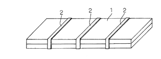
このように作製された一定の横幅(後述の冷凍室16の高さ分)を有する帯状のコア材料を、一定の縦幅、即ち凡そ冷凍冷蔵庫10の内箱12の両側壁及び背壁の合計の長さ(横の長さ)に裁断する。そして、図1に示すように、更に前記濾布面側よりも表面側の方が凹凸が大きいので、この裁断された、例えば2枚の平面視四角形の平面状のコア材1を、前記濾布面側が互いに外側となるように重合させた状態で、例えば30ミリメートル程度の幅を有するアウトガスが出ない複数の結束帯2で短手方向及び/又は長手方向を固定する。
The strip-shaped core material having a certain width (the height of the freezer compartment 16 to be described later) produced in this way is made to have a certain vertical width, that is, the total of both side walls and the back wall of the
このように、凹凸が小さい前記濾布面側が外側となるように重合させた状態で結束帯2で固定するようにしたのは、後に真空断熱パネルを作成して冷凍冷蔵庫10の内箱12の断熱材形成面側にこの真空断熱パネルを取付けて断熱材を発泡充填した際に、凹凸が大きいと、内箱12に凹凸ができて見栄えが悪くなるからである。
In this way, fixing with the
この結束帯2はPP(ポリプロピレン)や、PET(ポリエチレン・テレフタレート)などの合成樹脂材料で作成されたもので、この結束帯2を前述の如く2枚前記濾布面側を重合させた状態のコア材1に巻回した状態で、その端部近傍を熱シールにより接着する。
The
これにより、2枚のコア材1が互いにズレが無く一致した状態で固定されるが、このように2枚のコア材1を使用して所定の厚さのものとするのは、1枚のコア材で同様な厚さのものを作製しようとすると、厚さに応じた時間ばかりか、所望の密度を得るのに前記吸引装置による吸水時間がより長くなるので、前記コンベアの回転をより遅くしなければならず、生産効率が悪くなるからである。
As a result, the two
従って、同様な厚さのものを作製する場合には、薄いものを複数枚とした方が生産効率が良好である。仮に、複数枚、例えば3枚で構成する場合には、両外側に位置するコア材が凹凸が小さい前記濾布面側が外側となるように、重合させた状態で結束帯2で固定する。
Therefore, when manufacturing a thing with the same thickness, it is better to produce a plurality of thin ones for better production efficiency. If it is composed of a plurality of sheets, for example, three sheets, the core material positioned on both outer sides is fixed with the
なお、接着剤からアウトガスが少量でるが、複数枚のコア材を固定するのに、セロハンテープやガムテープなどの接着テープで結束してもよく、同様に接着剤や両面接着剤付きテープにより接着させてもよく、更にはPP(ポリプロピレン)や、PET(ポリエチレン・テレフタレート)などの熱シュリンクする合成樹脂材料で作成された網状の袋に挿入した上で熱を加えてシュリンクさせて固定してもよい。 In addition, although the outgas from the adhesive is small, it may be bound with adhesive tape such as cellophane tape or gum tape to fix multiple core materials, and similarly bonded with adhesive or tape with double-sided adhesive. Furthermore, after inserting into a net-like bag made of a heat-shrinking synthetic resin material such as PP (polypropylene) or PET (polyethylene terephthalate), it may be fixed by shrinking by applying heat. .
次に、この2枚重ねの繊維質のコア材1を100〜120℃の温度下で、例えば60分程度、アウトガスが発生しないように吸湿したその表面を乾燥させた後、真空パックする。即ち、乾燥させた後、三方をヒートシールした平面視四角形状の袋(容器)3の中に開口せる一方から前記結束帯2により固定された2枚のコア材1を入れ、これを真空槽(図示せず)内に入れて真空引きし、真空度を13.3Pa〜1.33Pa(0.1〜0.01Torr)とし、開口されている残りの一方をヒートシールして封止することにより密封し、厚さが、例えば10ミリメートル程度の真空断熱パネル4が形成される(図4参照)。
Next, the two-ply
前記袋3としては、ガスバリア性(ガス遮断性の高い)を有し、ヒートシール可能で、前記コア材1を収納して内部を真空に維持できるものであれば、どのようなものでも用いることができるが、例えばナイロン、アルミ蒸着PET(ポリエチレン・テレフタレート)、アルミ箔及び高密度ポリエチレンの4層構造からなるガスバリアフィルムを用いた袋が好ましく用いられる。
Any material can be used as the
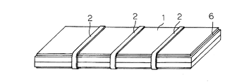
この真空断熱パネル4を形成する場合、図2に示すように、2枚のコア材1の両表面、即ち上のコア材1の表面及び下のコア材1の裏面の周縁部6を端部から10ミリメートル程度の範囲でプレスするか切除することによってこの周縁部以外の部分より薄くし、更に平面視四角形状の前記コア材1の四隅の角部を一番大きな面積が底面となるように水平板(図示せず)上に載置した状態で厚さ方向に切除して、例えば120度程度の2つの鈍角を形成する(図3参照)。
When forming this vacuum
従って、2枚のコア材1の両表面の周縁部6を例えば段差を有するようにか又は外端部に向けて薄くなるように斜めにかプレスし又は切除し、更に前記コア材1の四隅の角部を厚さ方向に切除することにより、真空引きの際に真空断熱パネル4の表面周縁部に袋3の余剰部分が重合して盛り上がったシワが発生しなくなる。
Accordingly, the
即ち、2枚のコア材1の表面周縁部を一部プレス又は切除しない場合には、真空引きの際に初めに袋3と2枚のコア材1との空間部が吸気され、更にこの2枚のコア材1中の空気が吸引されるため、このコア材1の表面周縁部の袋の余剰部分が重合して盛り上がってシワが発生したり、コア材を前記真空槽(図示せず)から出したときに大気圧がかかり、コア材1の表面周縁端部がコア材1方向に押されて、袋3の余剰部分が重合して盛り上がってシワが発生するが、本実施形態によれば、この発生が防止できる。
That is, when a part of the peripheral surface of the
仮に、盛り上がったシワが発生すると、この真空断熱パネル4を冷凍冷蔵庫10の内箱12の断熱材形成面側に接触させて取付けて、この外箱11と内箱12との間に発泡ポリウレタンを充填させて断熱材を形成する際に、このシワにより内箱12に凹凸ができ、見栄えの悪いものとなるが、本実施形態によれば、このような事態を回避できる。
If raised wrinkles are generated, the
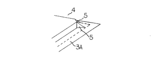
また、図5に示すように、前記コア材1の四隅の角部を厚さ方向に切除して2つの鈍角を形成したから、前述の真空引きの際に真空断熱パネル4の四隅における前記鈍角部分に袋3の余剰部分が重合してシワが発生して小さな2つの山5ができる場合がある。
Further, as shown in FIG. 5, since the corners of the four corners of the
しかし、四隅の角部を厚さ方向に切除して2つの鈍角を形成しない直角のままであると、四隅にシワによる大きな山が1つできることによりこの山が袋3まで伸びるということがあって袋の角部の強度が弱くて、ときに破けて真空破壊を起こしたり、またこの真空断熱パネルを冷凍冷蔵庫10の内箱12の断熱材形成面側に取付けて、この外箱11と内箱12との間に発泡ポリウレタンを充填させて断熱材を形成する際に、この大きな山により内箱12に凹凸ができることによる見栄えが悪くなる事態が発生することがあったが、これらの問題が解消できる。
However, if the corners of the four corners are cut in the thickness direction and remain at right angles that do not form two obtuse angles, this mountain may extend to the
このようにして、断熱効果が高いものを作製する必要から、真空引きすることにより密度が180〜400kg/m3程度の真空断熱パネル4を作製できるが、密度が高いものを作製するには多くのグラスウールが必要となりコスト高となるものであるから、コストなどを考慮して200kg/m3程度のものが望ましい。
In this way, since it is necessary to produce a material having a high heat insulation effect, the vacuum
なお、2枚のコア材1を結束帯2にて固定する前に、各コア材1の少なくとも一面周縁部をプレスするか切除したり、各コア材1の四隅の角部を切除して2つの鈍角を形成するようにしてもよいが、特に前者におけるプレスする場合や後者における鈍角を形成する場合には、2枚のコア材1を結束帯2にて固定した状態で行うのが一度の処理(プレスや切除)で済むため生産効率が良いため、固定後が望ましい。
Before fixing the two
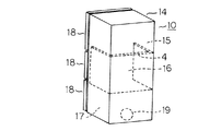
次に、以上のように作成された真空断熱パネル4を冷凍冷蔵庫10に用いるが、図6及び図7に基づき説明する。先ず、冷凍冷蔵庫10は、鋼板製の外箱11と合成樹脂材料で形成される内箱12及び両箱11、12間に充填される断熱材13とから構成される冷蔵庫本体14と、この冷蔵庫本体14の内部は断熱作用のある仕切壁により仕切られて上部より形成された上段の冷蔵室15、中段の冷凍室16及び下段の野菜室17の前面開口を開閉自在に閉塞する各断熱扉18とで構成される。この冷蔵室15及び野菜室17が冷蔵温度帯室であり、中段の冷凍室16が冷凍温度帯室である。
Next, although the vacuum
そして、最下段の冷蔵温度帯室である前記野菜室17の後方に設けられた機械室に配置された冷媒を吸入圧縮して高温高圧にする圧縮機19と、凝縮器、キャピラリチューブ、及び冷蔵用の冷却器、冷蔵用冷却器とを配管接続し、冷凍サイクルが構成される。冷凍サイクルの運転及び冷気循環用の送風機の運転により、冷気が上記各室に循環し、各室内が冷却される。
Then, a
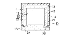
そして、図6及び図7に示すように、前記真空断熱パネル4を前記冷蔵庫本体14の横断平面形状に合わせて平面視コ字形状に折曲して、この真空断熱パネル4を冷凍温度帯室である冷凍室16を形成する背面及び両側面の内箱12の断熱材形成面側に貼り付けて、即ち真空断熱パネル4を冷凍室16の背面及び両側面を覆うように配置して、現場発泡方式によりウレタン断熱材20を充填発泡する。
Then, as shown in FIGS. 6 and 7, the vacuum
従って、この冷凍室16を形成する背面及び両側面には、このウレタン断熱材20と真空断熱パネル4とから構成される前記断熱材13が充填されることとなる。このように、冷凍室16を構成する内箱12の背面及び両側面の内側面に真空断熱パネル4を取付けて、両箱11、12間にウレタン断熱材20を発泡充填して断熱材13を形成するが、この断熱材13の一部に熱伝導率が低い(断熱性能が高い)真空断熱パネル4を用いることにより、熱の漏洩を低く抑えることができ、冷凍冷蔵庫10において断熱材13の肉厚を薄くすることができるものである。
Therefore, the
以下詳述するが、先ず図7に示すように、前記真空断熱パネル4を前記冷蔵庫本体14の横断平面形状に合わせて平面視コ字形状に折曲して、前記真空断熱パネル4の内側面の全域又は特定箇所に厚さ0.5〜1.5ミリメートルの弾性を有する両面接着剤付きテープ21を貼り付けて、両面接着剤付きテープ21によりこの真空断熱パネル4を厚さ0.4〜0.6mmの前記内箱12の冷凍室16内から見て外側面に貼り付けて固定する。この場合、両面接着剤付きテープ21を厚さ0.5〜1.5ミリメートルとするとその弾性によりコア材1(真空断熱パネル4)の凹凸を十分に吸収することができるが、1.5ミリメートル超とすると弾性が無くなり却って剛性により内箱12を部分的に押圧して凹凸を発生させることとなり、また0.5ミリメートル未満であると真空断熱パネル4の凹凸を弾性で吸収できずこの凹凸の影響を受けて、断熱材の発泡充填後に内箱12に凹凸が形成され、見栄えが悪くなるものである。
As will be described in detail below, first, as shown in FIG. 7, the vacuum
なお、両面接着剤付きテープ21は、弾性を有する、例えば発泡ポリエチレン又は軟質ポリウレタンフォームなどで作製されたものの両側に接着剤層を有するものであり、その弾性により真空断熱パネル4の凹凸を吸収できるものであればよい。
The double-sided adhesive-attached
従って、この両面接着剤付きテープ21に代えて弾性のある発泡性ホットメルトを内箱12の冷凍室16内から見て外側面に塗布しておいて、真空断熱パネル4を貼り付けて固定してよい。これにより、両面接着剤付きテープ21と同様に、その弾性力で真空断熱パネル4の凹凸を吸収できるものである。
Therefore, instead of the double-sided
この場合、作成された真空断熱パネル4において、コア材1の収納前の袋3における開口部を除く三辺の重合シール部3Aは12ミリメートルであり、袋3はもともと大きく作製してあるためにコア材1を袋3に挿入して真空引きした際に余剰部分も重合されて耳部分は12ミリメートルより長くなる。しかも、真空引きされた際に、開口部及びこの開口部に対向する辺以外の他の対向する辺のいずれかの側にコア材1が片寄って作製されることとなる。
In this case, in the created vacuum
そして、先ず真空引きをする前の開口部を形成していた耳部分3B(シール後の)は70〜80ミリメートルあるので、この耳部分3Bを外箱11方向の真空断熱パネル本体側に折り返して接着テープ等により固定しておき、次に前述の如く他の対向する辺(長辺)における片寄って長くなった耳部分も同様に外箱11方向の真空断熱パネル本体側に折り返して接着テープ等により固定しておく。即ち、これらの耳部分の真空断熱パネル本体側への折り返し方向は、両面接着剤付きテープ21により前記内箱12に前記真空断熱パネル4を取付ける際の内箱12から離れる方向である。
And since the ear | edge
即ち、発泡液が注入されて発泡する際に、真空断熱パネル4の前記耳部分を折り返して真空断熱パネル本体に固定していないと、外箱11側か内箱12側かのいずれにこれらの耳部分が曲るかわからず、仮に発泡圧により内箱12側に曲るとヒートブリッジ現象が生ずることとなるので、前述の如く、前記耳部分3Bや片寄って長くなった耳部分を内箱12から離れる方向(外箱方向)に折り返し、これらの耳部分が冷凍室16内から見て外側に位置するようにして両面接着剤付きテープ21により真空断熱パネル4を前記内箱12に取付けておくものである。また、折り返し部分が前記外側となるようにしたのは、内側、即ち内箱12側に折り返すと、これらの耳部分が内箱12を押圧して内箱12に凹凸が形成され、見栄えが悪くなるからである。
That is, when the foaming liquid is injected and foamed, if the ear portion of the vacuum
そして、以上のように両面接着剤付きテープ21により前記内箱12に前記真空断熱パネル4を取付け、外箱11の背壁に開口された注入口(図示せず)を介して発泡液を注入することによりウレタン断熱材20を形成し、冷凍室16を形成する面に位置する断熱材13はこのウレタン断熱材20と前記真空断熱パネル4とで形成され、それ以外の冷蔵室15及び野菜室17を形成する面に位置する断熱材13はウレタン断熱材20で形成されることとなる。
Then, as described above, the vacuum
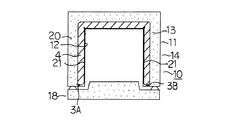
次に、図8に基づき、真空断熱パネル4を冷凍室16の後方及び両側方に位置する前記外箱12の背面及び両側面の断熱材形成面側に貼り付けてウレタン断熱材を発泡充填する第2の実施形態について説明する。先ず、前記真空断熱パネル4を前記冷蔵庫本体14の横断平面形状に合わせて平面視コ字形状に折曲して、前記真空断熱パネル4の外側面の全域又は特定箇所に両面接着剤付きテープ21を貼り付ける。
Next, based on FIG. 8, the vacuum
そして、両面接着剤付きテープ21によりこの真空断熱パネル4を前記外箱12の背面及び両側面の断熱材形成面側に貼り付けて、外箱11の背壁に開口された注入口(図示せず)を介して発泡液を注入することによりウレタン断熱材20を形成し、冷凍室16を形成する面に位置する断熱材13をこのウレタン断熱材20と前記真空断熱パネル4とで形成し、それ以外の冷蔵室15及び野菜室17を形成する面に位置する断熱材13はウレタン断熱材20で形成する。
And this vacuum
この場合、真空引きをする前の開口部を形成していた耳部分3B(シール後の)を内箱12方向の真空断熱パネル本体側に折り返して接着テープ等により固定しておき、次に前述の如く他の対向する辺(長辺)における片寄って長くなった耳部分も同様に内箱12方向の真空断熱パネル本体側に折り返して接着テープ等により固定しておく。即ち、これらの耳部分の真空断熱パネル本体側への折り返し方向は、両面接着剤付きテープ21により前記外箱11に前記真空断熱パネル4を取付ける際の外箱11から離れる方向である。
In this case, the
即ち、発泡液が注入されて発泡する際に、これらの耳部分が発泡圧により外箱11側に曲るとヒートブリッジ現象が生ずることとなるので、前述の如く、前記耳部分3Bや片寄って長くなった耳部分を外箱11から離れる方向(内箱方向)に折り返し、両面接着剤付きテープ21により真空断熱パネル4を前記外箱11に取付けておくものである。また、即ち外箱12側に折り返すと、これらの耳部分が外箱11を押圧して外箱11に凹凸が形成され、見栄えが悪くなるからである。
That is, when the foaming liquid is injected and foamed, if these ear portions bend toward the
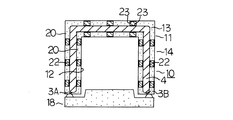
次に、図9に基づき、真空断熱パネル4を冷凍室16の後方及び側方に位置する内箱12及び外箱11から離間して配設し、ウレタン断熱材を発泡充填する第3の実施形態について説明する。先ず、前記真空断熱パネル4を前記冷蔵庫本体14の横断平面形状に合わせて平面視コ字形状に折曲する。
Next, based on FIG. 9, the vacuum
そして、冷凍室16を形成する箱体の背面及び両側面内にこの真空断熱パネル4を複数のスペーサ22を介してこの箱体を形成する内箱12及び外箱11から離間して配設する。即ち、内方に位置する前記スペーサ22は内箱12と真空断熱パネル4とに両面接着剤付きテープ23を介して接着し、また外方に位置する前記スペーサ22は外箱11と真空断熱パネル4とに両面接着剤付きテープ23を介して接着することにより、真空断熱パネル4を内箱12及び外箱11から離間して配設する。
The vacuum
そして、外箱11の背壁に開口された注入口(図示せず)を介して発泡液を注入することによりウレタン断熱材20を形成し、冷凍室16を形成する面に位置する断熱材13を前記真空断熱パネル4とこの真空断熱パネル4の内外側のウレタン断熱材20とで形成し、それ以外の冷蔵室15及び野菜室17を形成する面に位置する断熱材13はウレタン断熱材20で形成する。
And the urethane
この第3の実施形態では、前記真空断熱パネル4を内箱12及び外箱11から離間して配設するものであるから、真空引きをする前の開口部を形成していた耳部分3B(シール後の)や他の対向する辺(長辺)における片寄って長くなった耳部分は外箱11方向か内箱12方向のいずれかに真空断熱パネル本体側に折り返して接着テープ等により固定しておけばよい。
In this 3rd Embodiment, since the said vacuum
なお、以上の実施形態では、2枚の平面視矩形状のコア材1を濾布面側が外側となるように重合させた状態でアウトガスが出ない結束帯2で固定するようにして真空断熱パネルを作製したが、これに限らず、所定の厚さを有する1枚のコア材で真空断熱パネルを作製してもよい。
In the above embodiment, the vacuum heat insulation panel is fixed by fixing the two
なお、以上の第1乃至第3の実施形態において、箱体、即ち冷蔵庫本体14の横断平面形状に合わせた平面視コ字形状の真空断熱パネル4を冷凍温度帯室である冷凍室16の背面および両側面を覆うように配置したものであり、前記下段および上段の冷蔵温度帯室である冷蔵室15及び野菜室17の背面・両側面や、冷蔵庫本体14の天面及び底面や、前記下段および上段の冷蔵温度帯室と前記冷凍温度帯室とを仕切る仕切壁内や、前記下段および上段の冷蔵温度帯室の断熱扉18内に、真空断熱パネル4を配置しないものである。
In the first to third embodiments described above, the rear surface of the freezer compartment 16 that is a freezing temperature zone chamber is a box, that is, a U-shaped
以上本発明の実施態様について説明したが、上述の説明に基づいて当業者にとって種々の代替例、修正又は変形が可能であり、本発明はその趣旨を逸脱しない範囲で前述の種々の代替例、修正又は変形を包含するものである。 Although the embodiments of the present invention have been described above, various alternatives, modifications, and variations can be made by those skilled in the art based on the above description, and the present invention is not limited to the various alternatives described above without departing from the spirit of the present invention. It includes modifications or variations.
1 コア材
2 結束帯
3 袋
4 真空断熱パネル
10 冷凍冷蔵庫
11 外箱
12 内箱
13 断熱材
16 冷凍室
20 ウレタン断熱材
21 両面接着剤付きテープ
DESCRIPTION OF
Claims (13)
Priority Applications (1)
| Application Number | Priority Date | Filing Date | Title |
|---|---|---|---|
| JP2004113870A JP2005299972A (en) | 2004-04-08 | 2004-04-08 | Refrigerator |
Applications Claiming Priority (1)
| Application Number | Priority Date | Filing Date | Title |
|---|---|---|---|
| JP2004113870A JP2005299972A (en) | 2004-04-08 | 2004-04-08 | Refrigerator |
Publications (1)
| Publication Number | Publication Date |
|---|---|
| JP2005299972A true JP2005299972A (en) | 2005-10-27 |
Family
ID=35331721
Family Applications (1)
| Application Number | Title | Priority Date | Filing Date |
|---|---|---|---|
| JP2004113870A Pending JP2005299972A (en) | 2004-04-08 | 2004-04-08 | Refrigerator |
Country Status (1)
| Country | Link |
|---|---|
| JP (1) | JP2005299972A (en) |
Cited By (16)
| Publication number | Priority date | Publication date | Assignee | Title |
|---|---|---|---|---|
| EP1916465A1 (en) | 2006-10-26 | 2008-04-30 | Vestel Beyaz Esya Sanayi Ve Ticaret A.S. | Vacuumed heat barrier |
| JP2008267664A (en) * | 2007-04-18 | 2008-11-06 | Sharp Corp | Refrigerator |
| JP2009121697A (en) * | 2007-11-12 | 2009-06-04 | Sharp Corp | refrigerator |
| WO2009147106A1 (en) * | 2008-06-03 | 2009-12-10 | BSH Bosch und Siemens Hausgeräte GmbH | Domestic appliance in particular refrigerator |
| JP2010127421A (en) * | 2008-11-28 | 2010-06-10 | Mitsubishi Electric Corp | Vacuum thermal-insulating material and thermal insulation box |
| WO2010137081A1 (en) * | 2009-05-29 | 2010-12-02 | 日立アプライアンス株式会社 | Refrigerator equipped with vacuum insulation material |
| CN102506544A (en) * | 2011-10-20 | 2012-06-20 | 合肥美的荣事达电冰箱有限公司 | Method for manufacturing cabinet case of refrigerator |
| CN102564027A (en) * | 2008-03-19 | 2012-07-11 | 日立空调·家用电器株式会社 | Vacuum insulating panel and refrigerator |
| WO2013084647A1 (en) * | 2011-12-06 | 2013-06-13 | 株式会社 東芝 | Insulated cabinet |
| CN103196268A (en) * | 2013-04-22 | 2013-07-10 | 合肥华凌股份有限公司 | Box for refrigeration equipment and refrigeration equipment with box |
| DE102012215314A1 (en) * | 2012-08-29 | 2014-03-06 | BSH Bosch und Siemens Hausgeräte GmbH | Housing for a household refrigerator and household refrigeration appliance |
| WO2014103753A1 (en) * | 2012-12-25 | 2014-07-03 | 株式会社 東芝 | Method for manufacturing heat insulating box for refrigerator, and refrigerator |
| JP2014126252A (en) * | 2012-12-26 | 2014-07-07 | Toshiba Corp | Manufacturing method of heat insulation box of refrigerator |
| JP2014126223A (en) * | 2012-12-25 | 2014-07-07 | Toshiba Corp | Refrigerator |
| CN108195124A (en) * | 2018-02-28 | 2018-06-22 | 合肥美菱股份有限公司 | A kind of globoidal glass refrigerator door and its manufacture craft |
| JP2021073425A (en) * | 2019-11-06 | 2021-05-13 | 東芝ライフスタイル株式会社 | refrigerator |
-
2004
- 2004-04-08 JP JP2004113870A patent/JP2005299972A/en active Pending
Cited By (24)
| Publication number | Priority date | Publication date | Assignee | Title |
|---|---|---|---|---|
| EP1916465A1 (en) | 2006-10-26 | 2008-04-30 | Vestel Beyaz Esya Sanayi Ve Ticaret A.S. | Vacuumed heat barrier |
| JP2008267664A (en) * | 2007-04-18 | 2008-11-06 | Sharp Corp | Refrigerator |
| JP2009121697A (en) * | 2007-11-12 | 2009-06-04 | Sharp Corp | refrigerator |
| CN102564027A (en) * | 2008-03-19 | 2012-07-11 | 日立空调·家用电器株式会社 | Vacuum insulating panel and refrigerator |
| WO2009147106A1 (en) * | 2008-06-03 | 2009-12-10 | BSH Bosch und Siemens Hausgeräte GmbH | Domestic appliance in particular refrigerator |
| JP2010127421A (en) * | 2008-11-28 | 2010-06-10 | Mitsubishi Electric Corp | Vacuum thermal-insulating material and thermal insulation box |
| WO2010137081A1 (en) * | 2009-05-29 | 2010-12-02 | 日立アプライアンス株式会社 | Refrigerator equipped with vacuum insulation material |
| JP2010276310A (en) * | 2009-05-29 | 2010-12-09 | Hitachi Appliances Inc | Refrigerator with vacuum insulation |
| CN102449417A (en) * | 2009-05-29 | 2012-05-09 | 日立空调·家用电器株式会社 | Refrigerator equipped with vacuum insulation material |
| CN102506544A (en) * | 2011-10-20 | 2012-06-20 | 合肥美的荣事达电冰箱有限公司 | Method for manufacturing cabinet case of refrigerator |
| WO2013084647A1 (en) * | 2011-12-06 | 2013-06-13 | 株式会社 東芝 | Insulated cabinet |
| JP2013119967A (en) * | 2011-12-06 | 2013-06-17 | Toshiba Corp | Heat insulation cabinet |
| CN103975210B (en) * | 2011-12-06 | 2017-03-22 | 东芝生活电器株式会社 | Insulated cabinet |
| TWI558966B (en) * | 2011-12-06 | 2016-11-21 | 東芝生活電器股份有限公司 | Insulated cabinet |
| CN103975210A (en) * | 2011-12-06 | 2014-08-06 | 株式会社东芝 | Insulated cabinet |
| DE102012215314A1 (en) * | 2012-08-29 | 2014-03-06 | BSH Bosch und Siemens Hausgeräte GmbH | Housing for a household refrigerator and household refrigeration appliance |
| CN104870919A (en) * | 2012-12-25 | 2015-08-26 | 株式会社东芝 | Method for manufacturing heat insulating box for refrigerator, and refrigerator |
| JP2014126223A (en) * | 2012-12-25 | 2014-07-07 | Toshiba Corp | Refrigerator |
| WO2014103753A1 (en) * | 2012-12-25 | 2014-07-03 | 株式会社 東芝 | Method for manufacturing heat insulating box for refrigerator, and refrigerator |
| CN104870919B (en) * | 2012-12-25 | 2017-11-21 | 东芝生活电器株式会社 | The manufacture method and refrigerator of refrigerator heat insulating box |
| JP2014126252A (en) * | 2012-12-26 | 2014-07-07 | Toshiba Corp | Manufacturing method of heat insulation box of refrigerator |
| CN103196268A (en) * | 2013-04-22 | 2013-07-10 | 合肥华凌股份有限公司 | Box for refrigeration equipment and refrigeration equipment with box |
| CN108195124A (en) * | 2018-02-28 | 2018-06-22 | 合肥美菱股份有限公司 | A kind of globoidal glass refrigerator door and its manufacture craft |
| JP2021073425A (en) * | 2019-11-06 | 2021-05-13 | 東芝ライフスタイル株式会社 | refrigerator |
Similar Documents
| Publication | Publication Date | Title |
|---|---|---|
| JP5608457B2 (en) | Vacuum heat insulating material and refrigerator using the same | |
| CN103370587B (en) | Vacuum insulation for cold stores and freezers | |
| US7449227B2 (en) | Vacuum insulation panel and refrigerator incorporating the same | |
| CN101539361B (en) | refrigerator | |
| JP2005299972A (en) | Refrigerator | |
| JP5624305B2 (en) | Insulated container | |
| CN102401216B (en) | Vacuum insulating material and fridge using vacuum insulating material | |
| KR20030007544A (en) | Heat insulation box, and vacuum heat insulation material used therefor | |
| JP2005147591A (en) | Refrigerator | |
| KR100691917B1 (en) | Refrigerator | |
| JP3478792B2 (en) | refrigerator | |
| JP4297756B2 (en) | Core material for vacuum insulation | |
| JP6469232B2 (en) | refrigerator | |
| JP2013053722A (en) | Vacuum heat insulating material and heat insulating apparatus using the same | |
| JP6918462B2 (en) | Vacuum heat insulating material and refrigerator | |
| JP2013040717A (en) | Vacuum heat insulation material, and refrigerator using the same | |
| JP5401422B2 (en) | Vacuum heat insulating material and refrigerator using the same | |
| JP5945708B2 (en) | refrigerator | |
| JP2005172120A (en) | Vacuum heat insulating panel | |
| JP2005076726A (en) | Manufacturing method of vacuum heat insulating panel | |
| JP6535202B2 (en) | Vacuum insulation material and insulation box using the same | |
| JP2005076966A (en) | Cooling cabinet | |
| JP2005201505A (en) | Refrigerator | |
| JP2005076965A (en) | Cooling cabinet | |
| JP2015001290A (en) | Vacuum heat insulation material and refrigerator |