EP1916465A1 - Vacuumed heat barrier - Google Patents
Vacuumed heat barrier Download PDFInfo
- Publication number
- EP1916465A1 EP1916465A1 EP06123018A EP06123018A EP1916465A1 EP 1916465 A1 EP1916465 A1 EP 1916465A1 EP 06123018 A EP06123018 A EP 06123018A EP 06123018 A EP06123018 A EP 06123018A EP 1916465 A1 EP1916465 A1 EP 1916465A1
- Authority
- EP
- European Patent Office
- Prior art keywords
- vacuumed
- plate
- vacuum
- heat
- barrier
- Prior art date
- Legal status (The legal status is an assumption and is not a legal conclusion. Google has not performed a legal analysis and makes no representation as to the accuracy of the status listed.)
- Granted
Links
Images


Classifications
-
- F—MECHANICAL ENGINEERING; LIGHTING; HEATING; WEAPONS; BLASTING
- F16—ENGINEERING ELEMENTS AND UNITS; GENERAL MEASURES FOR PRODUCING AND MAINTAINING EFFECTIVE FUNCTIONING OF MACHINES OR INSTALLATIONS; THERMAL INSULATION IN GENERAL
- F16L—PIPES; JOINTS OR FITTINGS FOR PIPES; SUPPORTS FOR PIPES, CABLES OR PROTECTIVE TUBING; MEANS FOR THERMAL INSULATION IN GENERAL
- F16L59/00—Thermal insulation in general
- F16L59/06—Arrangements using an air layer or vacuum
- F16L59/065—Arrangements using an air layer or vacuum using vacuum
-
- F—MECHANICAL ENGINEERING; LIGHTING; HEATING; WEAPONS; BLASTING
- F25—REFRIGERATION OR COOLING; COMBINED HEATING AND REFRIGERATION SYSTEMS; HEAT PUMP SYSTEMS; MANUFACTURE OR STORAGE OF ICE; LIQUEFACTION SOLIDIFICATION OF GASES
- F25D—REFRIGERATORS; COLD ROOMS; ICE-BOXES; COOLING OR FREEZING APPARATUS NOT OTHERWISE PROVIDED FOR
- F25D2201/00—Insulation
- F25D2201/10—Insulation with respect to heat
- F25D2201/14—Insulation with respect to heat using subatmospheric pressure
Definitions
- This invention is related to the vacuumed heat barriers which reduce the heat transfer of the volumes having different internal environment temperatures both between each other and with the external environment and provide heat insulation, and the production methods thereof.
- the polyurethane foam which is one of these methods is used in the vast majority of the coolers produced presently in order to provide heat insulation.
- the polyurethane foam which is obtained by mixing two or more chemical liquids at certain ratios is injected between the refrigerator inner and outer surfaces and as a result of the chemical reaction that occurs; its volume expands, it passes to the solid state from the liquid state and completely fills the volume which remains between these surfaces In this way, the heat transfer of the cooler with the external environment is reduced and its isolation is provided.
- the other material which is used to provide heat isolation is the styrofoam.
- the styrofoam which is used as ready plates is used to provide heat isolation especially between the internal volumes at different temperatures.
- the vacuum isolation panel comprises support material, membrane, desiccant and getter.
- the materials such as perlite, stone wool, glass wool and silica are used as a support material.
- the vacuum retention time of vacuum isolation panels varies according to the gas permeability of the membrane used. Since the gas and the damp which may occur in the vacuum environment increase the pressure, getter and desiccant are used in order to prevent the gas and damp formation.
- the published patent document JP2005299972 also discloses a vacuum isolation panel.
- the vacuum isolation panel has a filling material comprising glass wool.
- the heat isolation material, urethane is filled to the side surfaces of the panel which is bent in the form of "U".
- a cardboard with corrugated structure is used as a support material.
- the air between the voids of the cardboard is vacuumed to some extent in the vacuum environment and this structure is subsequently coated with the film layers.
- the vacuumed heat barrier was developed as an alternative to the above-disclosed insulation systems and the production methods thereof.
- the vacuumed heat barriers which are produced as having a hollow or cellular structure from a material with low heat, gas and moisture conductivity and formed in a way that the inside is vacuumed and the tips are closed, are used to prevent the heat exchange of the cooler interior chambers with the external environment and between each other.
- the plate which is formed as cellular is placed into a vacuum chamber and the chamber pressure is reduced to low vacuum values.
- Said plate is coated with at least one insulation layer with low gas permeability in this vacuum environment and the chamber pressure is increased to the atmospheric pressure values.
- the cellular plates can be produced such that they can be vacuumed from a single point, they can also be formed in a structure in which each cell can be vacuumed separately. With the supports which are formed on the bottom and the top surfaces of the cellular plates, the subsidence of the materials under vacuum is prevented. Said plate structure is produced in a cost-effective manner with no need for the use of materials such as silica, aerogel, polyurethane foam, glass wool which are used in the old systems. In addition, no continuous vacuum application for the panels is required. When a vacuum process is applied to the cells of the vacuumed heat barrier; a very small amount of gas molecules remains inside these cells.
- the heat insulation in the coolers is provided by placing the vacuumed heat barrier modules into the regions of the cooler where the heat transfer occurs.
- An aim of this invention is to form a vacuumed heat barrier in order to reduce the heat transfer of the volumes having different internal environment temperatures both between each other and with the external environment and provide heat insulation.
- An aim of the invention is to perform a cost-effective vacuumed heat barrier production which will not necessitate re-vacuum due to the gas exchange.
- Another aim of the invention is to enable the use of the vacuumed heat barrier in presently used refrigerators, deep-freezers, industrial coolers, mobile coolers, cold stores and all other applications which require heat insulation.
- Vacuumed heat barrier (A) Hollow or cellular plate (1) Insulation layer (2) Void (3) Support feeders (4) Gas with low heat conductivity (5) Insulation sheets (6, 6') Insulation gas (7)
- the vacuumed heat barrier (A), of which side sectional view is provided in fig. 1, which is used to reduce the heat transfer of the volumes having different internal environment temperatures both between each other and with the external environment and provide heat insulation comprises a hollow or cellular plate (1) which is made of materials with low heat transmission coefficient and at least one insulation layer (2) which is used to protect the vacuum environment inside the hollow or cellular plate (1), covers the outer surfaces of the plate (1) completely and has a very low gas permeability.
- the voids (3) which remain between the support feeders (4) are the compartments where a vacuum environment is provided.
- Fig. 2 provides a side sectional view of the insulation layer (2).
- Said layer (2) is a structure which is obtained through closing the edge junctures of the sheets (6, 6') completely after a insulation gas (7) with low heat conductivity is filled between two superposed insulation sheets (6, 6') and called the gas jacket.
- the insulation sheets (6, 6') are chosen from the materials with very low gas permeability in order to prevent said gas (7) to leak out.
- the multi-layered barrier films which are produced through the lamination of the thin sheets made of polyethylene terephthalate (PET), aluminum (Al) and linear low density polyethylene (LLDPE) materials can be used as an insulation layer (2).
- PET polyethylene terephthalate
- Al aluminum
- LLDPE linear low density polyethylene
- the common characteristic of these said films is that their gas permeability is very low.
- the hollow or cellular plate (1) is placed into a vacuum chamber and the internal pressure of the chamber is reduced to very low values through vacuum.
- the vacuum process is performed after the internal volume of the vacuum chamber is filled with a gas or gas mixture with transmission coefficient which is lower than that of the air.
- the gasses which remain inside the internal volume of the plate even at a small amount are the gasses, instead of the air, that have a lower transmission coefficient than the air.
- Argon, carbon dioxide, krypton and xenon can be given as an example to the gasses used herein.
- the cost-effective vacuumed heat barriers with low thermal transmission can be obtained without falling to the vacuum levels which are necessary for the air.
- HV high vacuum
- UHV ultra high vacuum
- the outer surfaces of the plate (1) are coated with said insulation layer (2) in the same environment. Thereafter, the sealing of the plate (1) is provided by closing the holes thereof which are opened to the external environment for the vacuum process. Following this process, the pressure of the vacuum chamber is brought to the normal atmosphere pressure slowly and the plate (1) is removed from the vacuum chamber.
- these said gasses argon, carbon dioxide, xenon, krypton, air, etc.
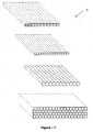
- Fig. 7 provides the schematic views of the alternative embodiments of the hollow or cellular plate (1). It is possible to use hollows or cells as polygonal or circular cross section. The plates with very low heat transmission coefficient are obtained through juxtaposing and superposing these said hollows or cells and vacuuming each cell separately.
Landscapes
- Engineering & Computer Science (AREA)
- General Engineering & Computer Science (AREA)
- Mechanical Engineering (AREA)
- Thermal Insulation (AREA)
- Refrigerator Housings (AREA)
Abstract
Description
- This invention is related to the vacuumed heat barriers which reduce the heat transfer of the volumes having different internal environment temperatures both between each other and with the external environment and provide heat insulation, and the production methods thereof.
- In the prior art, different methods are used in order to prevent the heat exchange of the coolers and/or the freezers with the external environment. The polyurethane foam which is one of these methods is used in the vast majority of the coolers produced presently in order to provide heat insulation. The polyurethane foam which is obtained by mixing two or more chemical liquids at certain ratios is injected between the refrigerator inner and outer surfaces and as a result of the chemical reaction that occurs; its volume expands, it passes to the solid state from the liquid state and completely fills the volume which remains between these surfaces In this way, the heat transfer of the cooler with the external environment is reduced and its isolation is provided. The other material which is used to provide heat isolation is the styrofoam. The styrofoam which is used as ready plates is used to provide heat isolation especially between the internal volumes at different temperatures.
- Another method which is used in order to provide heat isolation in the coolers is the vacuum isolation panels. In the system disclosed in patent document
JP2003227594 - The
published patent document JP2005299972 - In the
published patent document JP2005345025 - Although the heat transmission coefficients of the systems disclosed in said patent documents
JP2003227594 JP2005299972 JP2005345025 - In the patent document
US6158233 , the void which is formed between the panels is vacuumed and de-aerated without placing any filling material between the panels. The continuity of the vacuum environment in the system is provided with the vacuum pump which is placed into the system. The major disadvantage of this system is the requirement of continuous vacuum application. - In the system disclosed in the
published patent document JP9264490 - In the heat insulation panel which is disclosed in the
published patent document JP11201376 - The vacuumed heat barrier was developed as an alternative to the above-disclosed insulation systems and the production methods thereof. With the invention, the vacuumed heat barriers, which are produced as having a hollow or cellular structure from a material with low heat, gas and moisture conductivity and formed in a way that the inside is vacuumed and the tips are closed, are used to prevent the heat exchange of the cooler interior chambers with the external environment and between each other. The plate which is formed as cellular is placed into a vacuum chamber and the chamber pressure is reduced to low vacuum values. Said plate is coated with at least one insulation layer with low gas permeability in this vacuum environment and the chamber pressure is increased to the atmospheric pressure values. Although the cellular plates can be produced such that they can be vacuumed from a single point, they can also be formed in a structure in which each cell can be vacuumed separately. With the supports which are formed on the bottom and the top surfaces of the cellular plates, the subsidence of the materials under vacuum is prevented. Said plate structure is produced in a cost-effective manner with no need for the use of materials such as silica, aerogel, polyurethane foam, glass wool which are used in the old systems. In addition, no continuous vacuum application for the panels is required. When a vacuum process is applied to the cells of the vacuumed heat barrier; a very small amount of gas molecules remains inside these cells. By the presence of the gasses with low heat conductivity in the vacuum environment, the heat transfer that occurs due to the gas molecules which remain in the post-vacuum environment can be minimized. With the invention, the heat insulation in the coolers is provided by placing the vacuumed heat barrier modules into the regions of the cooler where the heat transfer occurs.
- An aim of this invention is to form a vacuumed heat barrier in order to reduce the heat transfer of the volumes having different internal environment temperatures both between each other and with the external environment and provide heat insulation.
- An aim of the invention is to perform a cost-effective vacuumed heat barrier production which will not necessitate re-vacuum due to the gas exchange.
- Another aim of the invention is to enable the use of the vacuumed heat barrier in presently used refrigerators, deep-freezers, industrial coolers, mobile coolers, cold stores and all other applications which require heat insulation.
- The vacuumed heat barrier is shown in the attached drawings, wherein:
- Fig. 1 is a side sectional view of the vacuumed heat barrier.
- Fig. 2 is a side sectional view of the insulation layer.
- Fig. 3 is a top sectional view of the heat barrier to which vacuum is applied from a single point.
- Fig. 4 is a top sectional view of the heat barrier to which vacuum is applied from a single point.
- Fig. 5 is a top view of the vacuumed heat barrier where vacuum is separately applied to each cell thereof.
- Fig. 6 is a top view of the vacuumed heat barrier where vacuum is separately applied to each cell thereof.
- Fig. 7 is the schematic views of the alternative embodiments of the hollow or the cellular plate.
- The parts in the figures are numbered one by one and the corresponding terms of these numbers are given below.
Vacuumed heat barrier (A)
Hollow or cellular plate (1)
Insulation layer (2)
Void (3)
Support feeders (4)
Gas with low heat conductivity (5)
Insulation sheets (6, 6')
Insulation gas (7) - The vacuumed heat barrier (A), of which side sectional view is provided in fig. 1, which is used to reduce the heat transfer of the volumes having different internal environment temperatures both between each other and with the external environment and provide heat insulation comprises a hollow or cellular plate (1) which is made of materials with low heat transmission coefficient and at least one insulation layer (2) which is used to protect the vacuum environment inside the hollow or cellular plate (1), covers the outer surfaces of the plate (1) completely and has a very low gas permeability. In order to ensure the plate (1) to resist against the force created by the atmospheric pressure on its outer side due to the vacuum which is formed inside the hollow or cellular plate (1), there are support feeders (4) in the inner side of the plate (1) and between at least two outer large surfaces thereof. The voids (3) which remain between the support feeders (4) are the compartments where a vacuum environment is provided.
- Fig. 2 provides a side sectional view of the insulation layer (2). Said layer (2) is a structure which is obtained through closing the edge junctures of the sheets (6, 6') completely after a insulation gas (7) with low heat conductivity is filled between two superposed insulation sheets (6, 6') and called the gas jacket. The insulation sheets (6, 6') are chosen from the materials with very low gas permeability in order to prevent said gas (7) to leak out.
- In another exemplary embodiment of the invention, it is possible to use a glass film as an insulation layer (2). In other exemplary embodiment of the invention, the multi-layered barrier films which are produced through the lamination of the thin sheets made of polyethylene terephthalate (PET), aluminum (Al) and linear low density polyethylene (LLDPE) materials can be used as an insulation layer (2). The common characteristic of these said films is that their gas permeability is very low. In another embodiment of the invention, it is possible to use at least two of above-mentioned gas jacket, glass film and said multi-layered barrier film together as an insulation layer (2). The reason why these said layers are used together is to minimize the gas transition between the external environment and the void (3) inside the plate (1).
- During the production of the vacuumed heat barrier (A), the hollow or cellular plate (1) is placed into a vacuum chamber and the internal pressure of the chamber is reduced to very low values through vacuum. In this method, the vacuum process is performed after the internal volume of the vacuum chamber is filled with a gas or gas mixture with transmission coefficient which is lower than that of the air. Thus, the gasses which remain inside the internal volume of the plate even at a small amount are the gasses, instead of the air, that have a lower transmission coefficient than the air. Argon, carbon dioxide, krypton and xenon can be given as an example to the gasses used herein. In the vacuum chamber, it is also possible to use air instead of said special gasses. However, with these gasses, the cost-effective vacuumed heat barriers with low thermal transmission can be obtained without falling to the vacuum levels which are necessary for the air. In the vacuum process which is performed in an environment where the air or the gasses other than the air are used in the vacuum chamber, it is preferred to reach high vacuum (HV) or ultra high vacuum (UHV) values in order to allow the plate (1) to meet the most effective heat isolation.
- After the vacuum process which is performed in a vacuum chamber where these said gasses (argon, carbon dioxide, xenon, krypton, air, etc...) exist, the outer surfaces of the plate (1) are coated with said insulation layer (2) in the same environment. Thereafter, the sealing of the plate (1) is provided by closing the holes thereof which are opened to the external environment for the vacuum process. Following this process, the pressure of the vacuum chamber is brought to the normal atmosphere pressure slowly and the plate (1) is removed from the vacuum chamber.
- In the plates (1) which are subjected to the vacuum process, it is possible to use a structure where the cells, each connected to each other, are vacuumed from a single point (figs. 3-4) or a structure where the cells, each independent from each other, are vacuumed separately (figs. 5-6).
- Fig. 7 provides the schematic views of the alternative embodiments of the hollow or cellular plate (1). It is possible to use hollows or cells as polygonal or circular cross section. The plates with very low heat transmission coefficient are obtained through juxtaposing and superposing these said hollows or cells and vacuuming each cell separately.
Claims (8)
- A vacuumed heat barrier (A) which is used to reduce the heat transfer of the volumes having different internal environment temperatures both between each other and with the external environment and provide heat insulation, characterized in that it comprises
a hollow or cellular plate (1) which is made of materials with low heat transmission coefficient;
at least one insulation layer (2) which is used to protect the vacuum environment inside the hollow plate (1), covers the outer surfaces of the plate (1) completely and has a very low gas permeability;
in order to ensure the plate (1) to resist against the force created by the atmospheric pressure on its outer side due to the vacuum which is formed inside the hollow plate (1), support feeders (4) in the inner side of the plate (1) and between two large surfaces thereof. - A vacuumed heat barrier (A) according to claim 1, wherein the insulation layer (2) is a structure which is obtained through closing the edge junctures of sheets (6, 6') completely after an insulation gas (7) with low heat conductivity is filled between two superposed insulation sheets (6, 6') with very low gas permeability and called the gas jacket.
- A vacuumed heat barrier (A) according to claim 1, wherein the insulation layer (2) is a glass film.
- A vacuumed heat barrier (A) according to claim 1, wherein the insulation layer (2) is the multi-layered barrier films which are produced through the lamination of the thin layers made of polyethylene terephthalate, aluminum and linear low density polyethylene materials.
- A vacuumed heat barrier (A) according to claims 2-4, wherein the insulation layer (2) is formed by using at least two of said gas jacket, glass film and said multi-layered barrier film together.
- A vacuumed heat barrier (A) according to claims 1-5, wherein the production method comprises the following stages:i. the hollow plate (1) is placed into a vacuum chamber, the internal volume of the chamber is composed of air or this volume is filled with a gas with lower thermal transmission coefficient than that of the air;ii. the internal pressure of the chamber is reduced to very low values through vacuum;iii. the outer surfaces of the plate (1) is coated with said insulation layer (2);iv. the holes of the plate (1) which are opened to the external environment for the vacuum process are closed to provide sealing;v. the pressure of the vacuum chamber is brought to the normal atmosphere pressure slowly and the plate (1) is removed from the vacuum chamber.
- A vacuumed heat barrier (A) according to claim 6, wherein in the second stage (ii) of the production method, in the plates (1) which are subjected to the vacuum process, a structure where the cells, each connected to each other, are vacuumed from a single point is used.
- A vacuumed heat barrier (A) according to claim 6, wherein in the second stage (ii) of the production method, in the plates (1) which are subjected to the vacuum process, a structure where the cells, each independent from each other, are separately vacuumed is used.
Priority Applications (1)
| Application Number | Priority Date | Filing Date | Title |
|---|---|---|---|
| EP06123018.1A EP1916465B1 (en) | 2006-10-26 | 2006-10-26 | Vacuumed heat barrier |
Applications Claiming Priority (1)
| Application Number | Priority Date | Filing Date | Title |
|---|---|---|---|
| EP06123018.1A EP1916465B1 (en) | 2006-10-26 | 2006-10-26 | Vacuumed heat barrier |
Publications (2)
| Publication Number | Publication Date |
|---|---|
| EP1916465A1 true EP1916465A1 (en) | 2008-04-30 |
| EP1916465B1 EP1916465B1 (en) | 2013-10-23 |
Family
ID=37891746
Family Applications (1)
| Application Number | Title | Priority Date | Filing Date |
|---|---|---|---|
| EP06123018.1A Not-in-force EP1916465B1 (en) | 2006-10-26 | 2006-10-26 | Vacuumed heat barrier |
Country Status (1)
| Country | Link |
|---|---|
| EP (1) | EP1916465B1 (en) |
Cited By (4)
| Publication number | Priority date | Publication date | Assignee | Title |
|---|---|---|---|---|
| WO2009124516A1 (en) * | 2008-04-09 | 2009-10-15 | Fraunhofer-Gesellschaft zur Förderung der angewandten Forschung e.V. | Heat insulation element and method for the production thereof |
| JP2014095426A (en) * | 2012-11-09 | 2014-05-22 | Zojirushi Corp | Vacuum heat insulation panel and method of manufacturing the same |
| CN104455846A (en) * | 2014-11-24 | 2015-03-25 | 常熟市宇力机械有限公司 | Flange connection sealing device |
| EP3387350A4 (en) * | 2015-12-08 | 2019-12-25 | Whirlpool Corporation | Vacuum insulation structures with a filler insulator |
Citations (25)
| Publication number | Priority date | Publication date | Assignee | Title |
|---|---|---|---|---|
| DE1257802B (en) * | 1956-06-12 | 1968-01-04 | Licentia Gmbh | Thermal insulation element for refrigerators |
| JPS57187242A (en) * | 1981-05-15 | 1982-11-17 | Tokyo Shibaura Electric Co | Vacuum heat insulating plate |
| US4409770A (en) * | 1980-02-06 | 1983-10-18 | Genbee Kawaguchi | Vacuum insulation spacer |
| JPS6196288A (en) * | 1984-10-17 | 1986-05-14 | 凸版印刷株式会社 | Heat-insulating material |
| EP0190582A2 (en) * | 1985-02-08 | 1986-08-13 | General Electric Company | Thermal insulating slabs for freezers and refrigerators comprising an envelope filled with precipitated silica which is subsequently compressed and the process for their manufacture |
| JPS61265481A (en) * | 1985-05-20 | 1986-11-25 | 松下冷機株式会社 | Heat insulator pack |
| WO1987001360A1 (en) * | 1985-09-03 | 1987-03-12 | Kataoka, Takashi | Heat-insulated container |
| JPS63163765A (en) * | 1986-12-25 | 1988-07-07 | 株式会社東芝 | Vacuum heat-insulating board |
| US5090981A (en) * | 1990-09-06 | 1992-02-25 | Owens-Corning Fiberglas Corporation | Method for making high R super insulation panel |
| US5327703A (en) * | 1993-03-23 | 1994-07-12 | Whirlpool Corporation | Vacuum panel assembly method |
| US5331789A (en) * | 1993-03-23 | 1994-07-26 | Whirlpool Corporation | Vacuum processing machine and method |
| JPH0755088A (en) * | 1993-08-12 | 1995-03-03 | Toshiba Corp | Vacuum heat insulating panel |
| JPH0771867A (en) * | 1993-09-03 | 1995-03-17 | Fujitsu General Ltd | Heat insulator unit and heat insulative box using the same |
| JPH0777383A (en) | 1993-09-06 | 1995-03-20 | Matsushita Electric Ind Co Ltd | Freezing refrigerator and heat insulating structure thereof |
| JPH0821594A (en) * | 1994-07-11 | 1996-01-23 | Gamakatsu Co Ltd | Heat insulating material |
| JPH08338684A (en) * | 1995-06-14 | 1996-12-24 | Toshiba Corp | Vacuum insulation material, vessel for vacuum insulation material, manufacture of vacuum insulation material, and refrigerator |
| EP0771995A1 (en) | 1995-11-28 | 1997-05-07 | G + H MONTAGE GmbH | Method for making superinsulation panel, superinsulation panel and its application |
| DE29711769U1 (en) | 1997-07-04 | 1997-10-30 | Schwille-Elektronik Produktions- und Vertriebs- GmbH, 85551 Kirchheim | Vacuum thermal insulation element |
| JPH10318666A (en) * | 1997-05-20 | 1998-12-04 | Dainippon Printing Co Ltd | Heat insulation member and its manufacturing method |
| JPH11201376A (en) | 1998-01-12 | 1999-07-30 | Mitsubishi Electric Corp | Vacuum heat insulation panel |
| US6158233A (en) | 1998-02-12 | 2000-12-12 | Aktiebolaget Electrolux | Vacuum insulated refrigerator or freezer cabinet |
| JP2003227594A (en) | 2002-02-05 | 2003-08-15 | Hitachi Ltd | Vacuum insulation panel and refrigerator using the same |
| EP1477752A2 (en) * | 2003-05-14 | 2004-11-17 | Chart Inc. | Improved cryogenic freezer |
| JP2005299972A (en) | 2004-04-08 | 2005-10-27 | Sanyo Electric Co Ltd | Refrigerator |
| JP2005345025A (en) | 2004-06-04 | 2005-12-15 | Hitachi Home & Life Solutions Inc | Refrigerator, vacuum heat insulating material, and its manufacturing method |
-
2006
- 2006-10-26 EP EP06123018.1A patent/EP1916465B1/en not_active Not-in-force
Patent Citations (26)
| Publication number | Priority date | Publication date | Assignee | Title |
|---|---|---|---|---|
| DE1257802B (en) * | 1956-06-12 | 1968-01-04 | Licentia Gmbh | Thermal insulation element for refrigerators |
| US4409770A (en) * | 1980-02-06 | 1983-10-18 | Genbee Kawaguchi | Vacuum insulation spacer |
| JPS57187242A (en) * | 1981-05-15 | 1982-11-17 | Tokyo Shibaura Electric Co | Vacuum heat insulating plate |
| JPS6196288A (en) * | 1984-10-17 | 1986-05-14 | 凸版印刷株式会社 | Heat-insulating material |
| EP0190582A2 (en) * | 1985-02-08 | 1986-08-13 | General Electric Company | Thermal insulating slabs for freezers and refrigerators comprising an envelope filled with precipitated silica which is subsequently compressed and the process for their manufacture |
| JPS61265481A (en) * | 1985-05-20 | 1986-11-25 | 松下冷機株式会社 | Heat insulator pack |
| WO1987001360A1 (en) * | 1985-09-03 | 1987-03-12 | Kataoka, Takashi | Heat-insulated container |
| JPS63163765A (en) * | 1986-12-25 | 1988-07-07 | 株式会社東芝 | Vacuum heat-insulating board |
| US5090981A (en) * | 1990-09-06 | 1992-02-25 | Owens-Corning Fiberglas Corporation | Method for making high R super insulation panel |
| US5327703A (en) * | 1993-03-23 | 1994-07-12 | Whirlpool Corporation | Vacuum panel assembly method |
| US5331789A (en) * | 1993-03-23 | 1994-07-26 | Whirlpool Corporation | Vacuum processing machine and method |
| JPH0755088A (en) * | 1993-08-12 | 1995-03-03 | Toshiba Corp | Vacuum heat insulating panel |
| JPH0771867A (en) * | 1993-09-03 | 1995-03-17 | Fujitsu General Ltd | Heat insulator unit and heat insulative box using the same |
| JPH0777383A (en) | 1993-09-06 | 1995-03-20 | Matsushita Electric Ind Co Ltd | Freezing refrigerator and heat insulating structure thereof |
| JPH0821594A (en) * | 1994-07-11 | 1996-01-23 | Gamakatsu Co Ltd | Heat insulating material |
| JPH08338684A (en) * | 1995-06-14 | 1996-12-24 | Toshiba Corp | Vacuum insulation material, vessel for vacuum insulation material, manufacture of vacuum insulation material, and refrigerator |
| EP0771995A1 (en) | 1995-11-28 | 1997-05-07 | G + H MONTAGE GmbH | Method for making superinsulation panel, superinsulation panel and its application |
| JPH09264490A (en) | 1995-11-28 | 1997-10-07 | G & H Montage Gmbh | Ultra-heat insulating panel and manufacture thereof |
| JPH10318666A (en) * | 1997-05-20 | 1998-12-04 | Dainippon Printing Co Ltd | Heat insulation member and its manufacturing method |
| DE29711769U1 (en) | 1997-07-04 | 1997-10-30 | Schwille-Elektronik Produktions- und Vertriebs- GmbH, 85551 Kirchheim | Vacuum thermal insulation element |
| JPH11201376A (en) | 1998-01-12 | 1999-07-30 | Mitsubishi Electric Corp | Vacuum heat insulation panel |
| US6158233A (en) | 1998-02-12 | 2000-12-12 | Aktiebolaget Electrolux | Vacuum insulated refrigerator or freezer cabinet |
| JP2003227594A (en) | 2002-02-05 | 2003-08-15 | Hitachi Ltd | Vacuum insulation panel and refrigerator using the same |
| EP1477752A2 (en) * | 2003-05-14 | 2004-11-17 | Chart Inc. | Improved cryogenic freezer |
| JP2005299972A (en) | 2004-04-08 | 2005-10-27 | Sanyo Electric Co Ltd | Refrigerator |
| JP2005345025A (en) | 2004-06-04 | 2005-12-15 | Hitachi Home & Life Solutions Inc | Refrigerator, vacuum heat insulating material, and its manufacturing method |
Cited By (4)
| Publication number | Priority date | Publication date | Assignee | Title |
|---|---|---|---|---|
| WO2009124516A1 (en) * | 2008-04-09 | 2009-10-15 | Fraunhofer-Gesellschaft zur Förderung der angewandten Forschung e.V. | Heat insulation element and method for the production thereof |
| JP2014095426A (en) * | 2012-11-09 | 2014-05-22 | Zojirushi Corp | Vacuum heat insulation panel and method of manufacturing the same |
| CN104455846A (en) * | 2014-11-24 | 2015-03-25 | 常熟市宇力机械有限公司 | Flange connection sealing device |
| EP3387350A4 (en) * | 2015-12-08 | 2019-12-25 | Whirlpool Corporation | Vacuum insulation structures with a filler insulator |
Also Published As
| Publication number | Publication date |
|---|---|
| EP1916465B1 (en) | 2013-10-23 |
Similar Documents
| Publication | Publication Date | Title |
|---|---|---|
| RU2260738C2 (en) | Evacuated panel for heat insulation of nonplanar surfaces | |
| US20030124300A1 (en) | Manufacturing a flexible thermoinsulating device | |
| CN100557289C (en) | In the gap, introduce the method for adiabatic system | |
| KR102583479B1 (en) | Sealed and insulated tank with anti-convection covering strips | |
| CN107108102A (en) | Vacuum tank | |
| JP2005147591A (en) | Refrigerator | |
| EP1916465B1 (en) | Vacuumed heat barrier | |
| EP1458551B1 (en) | Method for producing thermo-insulating cylindrical vacuum panels and panels thereby obtained | |
| WO2015186345A1 (en) | Vacuum heat insulating body, and heat insulating container and heat insulating wall employing same | |
| US20030101683A1 (en) | Evacuated panel for thermal insulation of cylindrical bodies | |
| US20030091776A1 (en) | Tubular thermoinsulating device and processes for the manufacture thereof | |
| US7823394B2 (en) | Thermal insulation technique for ultra low temperature cryogenic processor | |
| CN1439086A (en) | Evacuated panel for thermal insulation of cylindrical bodies | |
| RU2812078C1 (en) | Sealed and heat-insulating tank with anti-convection insulation seals | |
| JP2008208845A (en) | Composite heat insulating material | |
| JPH0821593A (en) | Heat insulating structural body |
Legal Events
| Date | Code | Title | Description |
|---|---|---|---|
| PUAI | Public reference made under article 153(3) epc to a published international application that has entered the european phase |
Free format text: ORIGINAL CODE: 0009012 |
|
| AK | Designated contracting states |
Kind code of ref document: A1 Designated state(s): AT BE BG CH CY CZ DE DK EE ES FI FR GB GR HU IE IS IT LI LT LU LV MC NL PL PT RO SE SI SK TR |
|
| AX | Request for extension of the european patent |
Extension state: AL BA HR MK RS |
|
| 17P | Request for examination filed |
Effective date: 20081022 |
|
| AKX | Designation fees paid |
Designated state(s): AT BE BG CH CY CZ DE DK EE ES FI FR GB GR HU IE IS IT LI LT LU LV MC NL PL PT RO SE SI SK TR |
|
| 17Q | First examination report despatched |
Effective date: 20111006 |
|
| GRAP | Despatch of communication of intention to grant a patent |
Free format text: ORIGINAL CODE: EPIDOSNIGR1 |
|
| INTG | Intention to grant announced |
Effective date: 20130809 |
|
| GRAS | Grant fee paid |
Free format text: ORIGINAL CODE: EPIDOSNIGR3 |
|
| GRAA | (expected) grant |
Free format text: ORIGINAL CODE: 0009210 |
|
| AK | Designated contracting states |
Kind code of ref document: B1 Designated state(s): AT BE BG CH CY CZ DE DK EE ES FI FR GB GR HU IE IS IT LI LT LU LV MC NL PL PT RO SE SI SK TR |
|
| REG | Reference to a national code |
Ref country code: GB Ref legal event code: FG4D |
|
| REG | Reference to a national code |
Ref country code: CH Ref legal event code: EP |
|
| REG | Reference to a national code |
Ref country code: AT Ref legal event code: REF Ref document number: 637804 Country of ref document: AT Kind code of ref document: T Effective date: 20131115 |
|
| REG | Reference to a national code |
Ref country code: IE Ref legal event code: FG4D |
|
| REG | Reference to a national code |
Ref country code: DE Ref legal event code: R096 Ref document number: 602006038926 Country of ref document: DE Effective date: 20131219 |
|
| REG | Reference to a national code |
Ref country code: NL Ref legal event code: VDEP Effective date: 20131023 |
|
| REG | Reference to a national code |
Ref country code: AT Ref legal event code: MK05 Ref document number: 637804 Country of ref document: AT Kind code of ref document: T Effective date: 20131023 |
|
| REG | Reference to a national code |
Ref country code: LT Ref legal event code: MG4D |
|
| PG25 | Lapsed in a contracting state [announced via postgrant information from national office to epo] |
Ref country code: FI Free format text: LAPSE BECAUSE OF FAILURE TO SUBMIT A TRANSLATION OF THE DESCRIPTION OR TO PAY THE FEE WITHIN THE PRESCRIBED TIME-LIMIT Effective date: 20131023 Ref country code: LT Free format text: LAPSE BECAUSE OF FAILURE TO SUBMIT A TRANSLATION OF THE DESCRIPTION OR TO PAY THE FEE WITHIN THE PRESCRIBED TIME-LIMIT Effective date: 20131023 Ref country code: NL Free format text: LAPSE BECAUSE OF FAILURE TO SUBMIT A TRANSLATION OF THE DESCRIPTION OR TO PAY THE FEE WITHIN THE PRESCRIBED TIME-LIMIT Effective date: 20131023 Ref country code: SE Free format text: LAPSE BECAUSE OF FAILURE TO SUBMIT A TRANSLATION OF THE DESCRIPTION OR TO PAY THE FEE WITHIN THE PRESCRIBED TIME-LIMIT Effective date: 20131023 Ref country code: IS Free format text: LAPSE BECAUSE OF FAILURE TO SUBMIT A TRANSLATION OF THE DESCRIPTION OR TO PAY THE FEE WITHIN THE PRESCRIBED TIME-LIMIT Effective date: 20140223 Ref country code: BE Free format text: LAPSE BECAUSE OF FAILURE TO SUBMIT A TRANSLATION OF THE DESCRIPTION OR TO PAY THE FEE WITHIN THE PRESCRIBED TIME-LIMIT Effective date: 20131023 |
|
| PG25 | Lapsed in a contracting state [announced via postgrant information from national office to epo] |
Ref country code: CY Free format text: LAPSE BECAUSE OF FAILURE TO SUBMIT A TRANSLATION OF THE DESCRIPTION OR TO PAY THE FEE WITHIN THE PRESCRIBED TIME-LIMIT Effective date: 20131023 Ref country code: AT Free format text: LAPSE BECAUSE OF FAILURE TO SUBMIT A TRANSLATION OF THE DESCRIPTION OR TO PAY THE FEE WITHIN THE PRESCRIBED TIME-LIMIT Effective date: 20131023 Ref country code: ES Free format text: LAPSE BECAUSE OF FAILURE TO SUBMIT A TRANSLATION OF THE DESCRIPTION OR TO PAY THE FEE WITHIN THE PRESCRIBED TIME-LIMIT Effective date: 20131023 Ref country code: LV Free format text: LAPSE BECAUSE OF FAILURE TO SUBMIT A TRANSLATION OF THE DESCRIPTION OR TO PAY THE FEE WITHIN THE PRESCRIBED TIME-LIMIT Effective date: 20131023 |
|
| REG | Reference to a national code |
Ref country code: CH Ref legal event code: PL |
|
| PG25 | Lapsed in a contracting state [announced via postgrant information from national office to epo] |
Ref country code: PT Free format text: LAPSE BECAUSE OF FAILURE TO SUBMIT A TRANSLATION OF THE DESCRIPTION OR TO PAY THE FEE WITHIN THE PRESCRIBED TIME-LIMIT Effective date: 20140224 |
|
| REG | Reference to a national code |
Ref country code: DE Ref legal event code: R097 Ref document number: 602006038926 Country of ref document: DE |
|
| REG | Reference to a national code |
Ref country code: IE Ref legal event code: MM4A |
|
| PG25 | Lapsed in a contracting state [announced via postgrant information from national office to epo] |
Ref country code: CH Free format text: LAPSE BECAUSE OF NON-PAYMENT OF DUE FEES Effective date: 20131031 Ref country code: EE Free format text: LAPSE BECAUSE OF FAILURE TO SUBMIT A TRANSLATION OF THE DESCRIPTION OR TO PAY THE FEE WITHIN THE PRESCRIBED TIME-LIMIT Effective date: 20131023 Ref country code: MC Free format text: LAPSE BECAUSE OF FAILURE TO SUBMIT A TRANSLATION OF THE DESCRIPTION OR TO PAY THE FEE WITHIN THE PRESCRIBED TIME-LIMIT Effective date: 20131023 Ref country code: LI Free format text: LAPSE BECAUSE OF NON-PAYMENT OF DUE FEES Effective date: 20131031 |
|
| PG25 | Lapsed in a contracting state [announced via postgrant information from national office to epo] |
Ref country code: SK Free format text: LAPSE BECAUSE OF FAILURE TO SUBMIT A TRANSLATION OF THE DESCRIPTION OR TO PAY THE FEE WITHIN THE PRESCRIBED TIME-LIMIT Effective date: 20131023 Ref country code: CZ Free format text: LAPSE BECAUSE OF FAILURE TO SUBMIT A TRANSLATION OF THE DESCRIPTION OR TO PAY THE FEE WITHIN THE PRESCRIBED TIME-LIMIT Effective date: 20131023 Ref country code: RO Free format text: LAPSE BECAUSE OF FAILURE TO SUBMIT A TRANSLATION OF THE DESCRIPTION OR TO PAY THE FEE WITHIN THE PRESCRIBED TIME-LIMIT Effective date: 20131023 Ref country code: IT Free format text: LAPSE BECAUSE OF FAILURE TO SUBMIT A TRANSLATION OF THE DESCRIPTION OR TO PAY THE FEE WITHIN THE PRESCRIBED TIME-LIMIT Effective date: 20131023 Ref country code: PL Free format text: LAPSE BECAUSE OF FAILURE TO SUBMIT A TRANSLATION OF THE DESCRIPTION OR TO PAY THE FEE WITHIN THE PRESCRIBED TIME-LIMIT Effective date: 20131023 |
|
| PLBE | No opposition filed within time limit |
Free format text: ORIGINAL CODE: 0009261 |
|
| STAA | Information on the status of an ep patent application or granted ep patent |
Free format text: STATUS: NO OPPOSITION FILED WITHIN TIME LIMIT |
|
| REG | Reference to a national code |
Ref country code: FR Ref legal event code: ST Effective date: 20140804 |
|
| GBPC | Gb: european patent ceased through non-payment of renewal fee |
Effective date: 20140123 |
|
| PG25 | Lapsed in a contracting state [announced via postgrant information from national office to epo] |
Ref country code: DK Free format text: LAPSE BECAUSE OF FAILURE TO SUBMIT A TRANSLATION OF THE DESCRIPTION OR TO PAY THE FEE WITHIN THE PRESCRIBED TIME-LIMIT Effective date: 20131023 |
|
| 26N | No opposition filed |
Effective date: 20140724 |
|
| PG25 | Lapsed in a contracting state [announced via postgrant information from national office to epo] |
Ref country code: IE Free format text: LAPSE BECAUSE OF NON-PAYMENT OF DUE FEES Effective date: 20131026 |
|
| REG | Reference to a national code |
Ref country code: DE Ref legal event code: R097 Ref document number: 602006038926 Country of ref document: DE Effective date: 20140724 |
|
| PG25 | Lapsed in a contracting state [announced via postgrant information from national office to epo] |
Ref country code: FR Free format text: LAPSE BECAUSE OF NON-PAYMENT OF DUE FEES Effective date: 20131223 Ref country code: GB Free format text: LAPSE BECAUSE OF NON-PAYMENT OF DUE FEES Effective date: 20140123 |
|
| PGFP | Annual fee paid to national office [announced via postgrant information from national office to epo] |
Ref country code: TR Payment date: 20140825 Year of fee payment: 9 |
|
| PG25 | Lapsed in a contracting state [announced via postgrant information from national office to epo] |
Ref country code: SI Free format text: LAPSE BECAUSE OF FAILURE TO SUBMIT A TRANSLATION OF THE DESCRIPTION OR TO PAY THE FEE WITHIN THE PRESCRIBED TIME-LIMIT Effective date: 20131023 |
|
| PGFP | Annual fee paid to national office [announced via postgrant information from national office to epo] |
Ref country code: DE Payment date: 20141231 Year of fee payment: 9 |
|
| PG25 | Lapsed in a contracting state [announced via postgrant information from national office to epo] |
Ref country code: LU Free format text: LAPSE BECAUSE OF NON-PAYMENT OF DUE FEES Effective date: 20131026 Ref country code: HU Free format text: LAPSE BECAUSE OF FAILURE TO SUBMIT A TRANSLATION OF THE DESCRIPTION OR TO PAY THE FEE WITHIN THE PRESCRIBED TIME-LIMIT; INVALID AB INITIO Effective date: 20061026 Ref country code: BG Free format text: LAPSE BECAUSE OF FAILURE TO SUBMIT A TRANSLATION OF THE DESCRIPTION OR TO PAY THE FEE WITHIN THE PRESCRIBED TIME-LIMIT Effective date: 20131023 |
|
| PG25 | Lapsed in a contracting state [announced via postgrant information from national office to epo] |
Ref country code: GR Free format text: LAPSE BECAUSE OF NON-PAYMENT OF DUE FEES Effective date: 20131023 |
|
| REG | Reference to a national code |
Ref country code: DE Ref legal event code: R119 Ref document number: 602006038926 Country of ref document: DE |
|
| PG25 | Lapsed in a contracting state [announced via postgrant information from national office to epo] |
Ref country code: GR Free format text: LAPSE BECAUSE OF FAILURE TO SUBMIT A TRANSLATION OF THE DESCRIPTION OR TO PAY THE FEE WITHIN THE PRESCRIBED TIME-LIMIT Effective date: 20140124 |
|
| PG25 | Lapsed in a contracting state [announced via postgrant information from national office to epo] |
Ref country code: DE Free format text: LAPSE BECAUSE OF NON-PAYMENT OF DUE FEES Effective date: 20160503 |
|
| PG25 | Lapsed in a contracting state [announced via postgrant information from national office to epo] |
Ref country code: TR Free format text: LAPSE BECAUSE OF NON-PAYMENT OF DUE FEES Effective date: 20151026 |