JP2009121697A - Refrigerator - Google Patents
Refrigerator Download PDFInfo
- Publication number
- JP2009121697A JP2009121697A JP2007292785A JP2007292785A JP2009121697A JP 2009121697 A JP2009121697 A JP 2009121697A JP 2007292785 A JP2007292785 A JP 2007292785A JP 2007292785 A JP2007292785 A JP 2007292785A JP 2009121697 A JP2009121697 A JP 2009121697A
- Authority
- JP
- Japan
- Prior art keywords
- heat insulation
- vacuum heat
- box
- heat insulating
- inner box
- Prior art date
- Legal status (The legal status is an assumption and is not a legal conclusion. Google has not performed a legal analysis and makes no representation as to the accuracy of the status listed.)
- Pending
Links
Images


Abstract
Description
本発明は、断熱箱体内に真空断熱パネルを備えた冷蔵庫に関する。 The present invention relates to a refrigerator provided with a vacuum heat insulation panel in a heat insulation box.
従来の冷蔵庫は特許文献1に開示されている。図9はこの冷蔵庫の本体筐体を形成する断熱箱体の上面断面図を示している。断熱箱体10は外箱11と内箱12の間に発泡断熱材13が充填され、内箱12により複数の貯蔵室7が区分けして形成される。断熱箱体10の両側面及び背面には外箱11に固着した平板状の真空断熱パネル20が設けられる。
A conventional refrigerator is disclosed in Patent Document 1. FIG. 9 shows a top cross-sectional view of a heat insulating box forming the main body casing of the refrigerator. The
各面の真空断熱パネル20の周囲には隙間30aが設けられる。隙間30aによって発泡断熱材13の原液が浸透するための流路が形成される。該流路を発泡断熱材13の原液が流通し、真空断熱パネル20と内箱12との間に発泡断熱材13が充填される。真空断熱パネル20によって断熱箱体10の断熱性を向上することができる。
A
しかしながら、上記従来の冷蔵庫によると、平板状の真空断熱パネル20が断熱箱体10の各面にそれぞれ設けられ、各真空断熱パネル20の周囲に発泡断熱材13を浸透させるための隙間30aが形成される。このため、外箱11の表面積に対する真空断熱パネル20の被覆率が低く55〜60%程度になる。このため、断熱箱体10の断熱性を充分向上することができない問題があった。
However, according to the conventional refrigerator, the flat vacuum
本発明は、断熱性を向上することができる冷蔵庫を提供することを目的とする。 An object of this invention is to provide the refrigerator which can improve heat insulation.
上記目的を達成するために本発明は、前面を開口する内箱と、前記内箱の外側を覆う外箱と、前記内箱と前記外箱との間に充填される発泡断熱材と、芯材を外被材で覆って内部が減圧されるとともに前記内箱と前記外箱との間に配される真空断熱パネルとを有する断熱箱体を備えた冷蔵庫において、前記真空断熱パネルを前記内箱の両側面及び背面を覆うように断面コ字型に折曲したことを特徴としている。 In order to achieve the above object, the present invention includes an inner box that opens at the front, an outer box that covers the outside of the inner box, a foam heat insulating material that is filled between the inner box and the outer box, and a core. In a refrigerator comprising a heat insulating box body having a vacuum heat insulating panel disposed between the inner box and the outer box while the inside is reduced in pressure by covering the material with a jacket material, the vacuum heat insulating panel is It is characterized by being folded into a U-shaped cross section so as to cover both sides and the back of the box.
この構成によると、外箱と内箱との間に真空断熱パネルを配して発泡断熱材が充填され、断熱箱体が形成される。真空断熱パネルは断面コ字型に折曲され、内箱の両側面と背面とを覆うように配置される。 According to this configuration, the vacuum heat insulation panel is disposed between the outer box and the inner box, and the foam heat insulating material is filled to form a heat insulation box. The vacuum heat insulation panel is bent into a U-shaped cross section and is disposed so as to cover both side surfaces and the back surface of the inner box.
また本発明は、上記構成の冷蔵庫において、複数の前記真空断熱パネルを上下に並設し、隣接する前記真空断熱パネルの一方を前記外箱に近接するとともに他方を前記内箱に近接したことを特徴としている。この構成によると、例えば、上方に配される真空断熱パネルが外箱に貼着され、該真空断熱パネルに隣接して下方に配される真空パネルが内箱に貼着される。 Moreover, in the refrigerator having the above-described configuration, the present invention includes a plurality of the vacuum heat insulating panels arranged vertically, and one of the adjacent vacuum heat insulating panels is close to the outer box and the other is close to the inner box. It is a feature. According to this configuration, for example, the vacuum heat insulation panel disposed above is attached to the outer box, and the vacuum panel disposed below and adjacent to the vacuum heat insulation panel is attached to the inner box.
また本発明は、上記構成の冷蔵庫において、正面投影において隙間なく複数の前記真空断熱パネルを並設したことを特徴としている。この構成によると、隣接する真空断熱パネルは一方の下端と他方の上端との間には上下に連通した隙間が形成される。 Further, the present invention is characterized in that in the refrigerator configured as described above, a plurality of the vacuum heat insulation panels are arranged in parallel without gaps in front projection. According to this structure, the adjacent vacuum heat insulation panel has a gap communicating vertically between one lower end and the other upper end.
また本発明は、上記構成の冷蔵庫において、前記外箱の背面側に前記発泡断熱材の原液を注入する注入口を設け、前記注入口を前記内箱に近接した前記真空断熱パネルに対向配置したことを特徴としている。この構成によると、内箱の開口部側を下方にして外箱の背面側の注入口に発泡断熱材の原液を吐出するノズルが挿入される。ノズルの先端は内箱に近接する真空断熱パネルに対向して配されて真空断熱パネルに接触せず、ノズルから吐出された発泡断熱材の原液が該真空断熱パネルの外面側を流通する。 Further, in the refrigerator having the above-described configuration, the refrigerator is provided with an inlet for injecting the stock solution of the foam heat insulating material on the back side of the outer box, and the inlet is disposed to face the vacuum heat insulating panel close to the inner box. It is characterized by that. According to this configuration, the nozzle for discharging the stock solution of the foam heat insulating material is inserted into the inlet on the back side of the outer box with the opening side of the inner box facing downward. The tip of the nozzle is arranged to face the vacuum heat insulation panel close to the inner box and does not contact the vacuum heat insulation panel, and the stock solution of the foam heat insulating material discharged from the nozzle circulates on the outer surface side of the vacuum heat insulation panel.
また本発明は、上記構成の冷蔵庫において、前記断熱箱体は複数の貯蔵室を仕切る断熱壁を一体に有し、隙間を介して複数の前記真空断熱パネルを上下に並設するとともに、前記断熱壁の後方及び側方に前記隙間を配置したことを特徴としている。 Further, in the refrigerator having the above-described configuration, the heat insulating box integrally includes a heat insulating wall that partitions a plurality of storage chambers, and the plurality of vacuum heat insulating panels are arranged in parallel above and below through a gap, and the heat insulating The gap is arranged behind and on the side of the wall.
この構成によると、複数の真空断熱パネルが上下に並設され、真空断熱パネル間の隙間が貯蔵室を仕切る断熱壁と同じ高さに配される。これにより、各貯蔵室の両側面及び背面に真空断熱パネルが配置され、断熱壁の後方及び側方に真空断熱パネルが配置されない。発泡断熱材は該隙間によって真空断熱パネルの内箱側と外箱側に流通して充填される。 According to this configuration, the plurality of vacuum heat insulating panels are arranged in parallel up and down, and the gap between the vacuum heat insulating panels is arranged at the same height as the heat insulating walls that partition the storage chamber. Thereby, a vacuum heat insulation panel is arrange | positioned at the both sides | surfaces and the back surface of each store room, and a vacuum heat insulation panel is not arrange | positioned at the back and the side of a heat insulation wall. The foam heat insulating material is circulated and filled in the inner box side and the outer box side of the vacuum heat insulating panel through the gap.
また本発明は、上記構成の冷蔵庫において、前記外箱の背面側に前記発泡断熱材の原液を注入する注入口を設け、前記注入口を前記隙間に対向配置したことを特徴としている。この構成によると、内箱の開口部側を下方にして外箱の背面側の注入口に発泡断熱材の原液を吐出するノズルが挿入される。ノズルの先端は真空断熱パネル間の隙間に配されて真空断熱パネルに接触せず、ノズルから吐出された発泡断熱材の原液が真空断熱パネルの内面側及び外面側を流通する。 Further, the present invention is characterized in that in the refrigerator configured as described above, an inlet for injecting the stock solution of the foam heat insulating material is provided on the back side of the outer box, and the inlet is arranged to face the gap. According to this configuration, the nozzle for discharging the stock solution of the foam heat insulating material is inserted into the inlet on the back side of the outer box with the opening side of the inner box facing downward. The tip of the nozzle is disposed in the gap between the vacuum heat insulation panels and does not contact the vacuum heat insulation panel, and the stock solution of the foam heat insulating material discharged from the nozzle flows through the inner surface side and the outer surface side of the vacuum heat insulation panel.
また本発明は、上記構成の冷蔵庫において、前記真空断熱パネルを前記内箱及び前記外箱から離して配置したことを特徴としている。この構成によると、真空断熱パネルと内箱との間に発泡断熱材が充填され、真空断熱パネルと外箱との間に発泡断熱材が充填される。 Moreover, the present invention is characterized in that, in the refrigerator having the above-described configuration, the vacuum heat insulation panel is arranged apart from the inner box and the outer box. According to this configuration, the foam heat insulating material is filled between the vacuum heat insulating panel and the inner box, and the foam heat insulating material is filled between the vacuum heat insulating panel and the outer box.
また本発明は、上記構成の冷蔵庫において、前記真空断熱パネルと前記内箱との距離を前記真空断熱パネルと前記外箱との距離よりも大きくしたことを特徴としている。 In the refrigerator having the above-described configuration, the distance between the vacuum heat insulation panel and the inner box is greater than the distance between the vacuum heat insulation panel and the outer box.
また本発明は、上記構成の冷蔵庫において、前記内箱に固着して前記真空断熱パネルを支持する支持部材を設けたことを特徴としている。 In the refrigerator having the above-described configuration, the present invention is characterized in that a support member that is fixed to the inner box and supports the vacuum heat insulation panel is provided.
また本発明は、上記構成の冷蔵庫において、一の前記真空断熱パネルと他の前記真空断熱パネルとの厚みが異なることを特徴としている。この構成によると、例えば、野菜室を囲む真空断熱パネルが薄く形成され、冷凍室を囲む真空断熱パネルが厚く形成される。 Moreover, the present invention is characterized in that, in the refrigerator configured as described above, the thickness of one vacuum heat insulation panel and the other vacuum heat insulation panel are different. According to this configuration, for example, the vacuum heat insulation panel surrounding the vegetable compartment is formed thin, and the vacuum heat insulation panel surrounding the freezer compartment is formed thick.
本発明によると、真空断熱パネルを内箱の両側面及び背面を覆うようにコ字型に折曲したので、従来のように断熱箱体の側面と背面との境界に発泡断熱材の流路を形成する隙間が形成されない。これにより、発泡断熱材の流路を形成する隙間の体積を削減することができ、真空断熱パネルの被覆率を増加して断熱箱体及び冷蔵庫の断熱性を向上することができる。 According to the present invention, since the vacuum heat insulation panel is bent in a U shape so as to cover both side surfaces and the back surface of the inner box, the flow path of the foam heat insulating material at the boundary between the side surface and the back surface of the heat insulation box body as in the past. No gap is formed. Thereby, the volume of the clearance gap which forms the flow path of a foam heat insulating material can be reduced, the coverage of a vacuum heat insulation panel can be increased, and the heat insulation of a heat insulation box and a refrigerator can be improved.
また本発明によると、複数の真空断熱パネルを上下に並設し、隣接する真空断熱パネルの一方を外箱に近接するとともに他方を内箱に近接したので、隣接する真空断熱パネルを正面投影において接近して配置できる。これにより、真空断熱パネルの被覆率をより増加して断熱箱体及び冷蔵庫の断熱性を向上することができる。また、隣接する真空断熱パネル間には上下に連通する隙間が形成されるため、発泡断熱材を容易に流通させることができる。 Further, according to the present invention, a plurality of vacuum heat insulation panels are arranged vertically, and one of the adjacent vacuum heat insulation panels is close to the outer box and the other is close to the inner box. Can be placed close together. Thereby, the coverage of a vacuum heat insulation panel can be increased more and the heat insulation of a heat insulation box and a refrigerator can be improved. Moreover, since the clearance gap connected to the up-down is formed between adjacent vacuum heat insulation panels, a foam heat insulating material can be distribute | circulated easily.
また本発明によると、正面投影において隙間なく複数の真空断熱パネルを並設したので、真空断熱パネルの被覆率をより増加することができる。また、実質的な断熱厚みが増加して断熱箱体の断熱性を更に向上することができる。 Further, according to the present invention, since the plurality of vacuum heat insulation panels are arranged side by side with no gap in the front projection, the coverage of the vacuum heat insulation panel can be further increased. Moreover, substantial heat insulation thickness increases and the heat insulation of a heat insulation box can be improved further.
また本発明によると、発泡断熱材の原液を注入する注入口を内箱に近接した真空断熱パネルに対向配置したので、吐出用のノズルを真空断熱パネルに接触させずに発泡断熱材の原液を注入することができる。従って、発泡断熱材の原液が円滑に流動し、ボイド等を防止して発泡断熱材を均一に充填することができる。 In addition, according to the present invention, since the injection port for injecting the raw material for the foam heat insulating material is disposed opposite to the vacuum heat insulating panel close to the inner box, the raw solution for the foam heat insulating material can be supplied without contacting the discharge nozzle with the vacuum heat insulating panel. Can be injected. Accordingly, the stock solution of the foam heat insulating material flows smoothly, and voids and the like can be prevented and the foam heat insulating material can be uniformly filled.
また本発明によると、貯蔵室を仕切る断熱壁の後方及び側方に配置された隙間を介して複数の真空断熱パネルを上下に並設したので、各貯蔵室に対する真空断熱パネルの被覆率を増加することができる。従って、断熱箱体及び冷蔵庫の断熱性を向上することができる。更に、真空断熱パネルの使用量を削減して冷蔵庫のコストを削減することができる。 In addition, according to the present invention, since the plurality of vacuum heat insulation panels are arranged vertically above and below the heat insulation wall partitioning the storage chamber, the vacuum insulation panel coverage for each storage chamber is increased. can do. Therefore, the heat insulation of a heat insulation box and a refrigerator can be improved. Furthermore, it is possible to reduce the cost of the refrigerator by reducing the amount of vacuum insulation panel used.
また本発明によると、発泡断熱材の原液を注入する注入口を真空断熱パネル間の隙間に対向配置したので、吐出用のノズルを真空断熱パネルに接触させずに発泡断熱材の原液を注入することができる。従って、発泡断熱材の原液が円滑に流動し、ボイド等を防止して発泡断熱材を均一に充填することができる。 Further, according to the present invention, since the injection port for injecting the stock solution of the foam heat insulating material is disposed opposite to the gap between the vacuum heat insulating panels, the stock solution of the foam heat insulating material is injected without bringing the discharge nozzle into contact with the vacuum heat insulating panel. be able to. Accordingly, the stock solution of the foam heat insulating material flows smoothly, and voids and the like can be prevented and the foam heat insulating material can be uniformly filled.
また本発明によると、真空断熱パネルを内箱及び外箱から離して配置したので、背面に凹凸のある内箱や配管が設けられる外箱と真空断熱パネルとの間に発泡断熱材が流通する流路を確保して充填不足による断熱性の低下を防止することができる。 According to the present invention, since the vacuum heat insulation panel is disposed away from the inner box and the outer box, the foam heat insulating material circulates between the outer case and the vacuum heat insulation panel provided with the inner box and the piping having the unevenness on the back surface. A flow path can be secured to prevent a decrease in heat insulation due to insufficient filling.
また本発明によると、真空断熱パネルと内箱との距離を真空断熱パネルと外箱との距離よりも大きくしたので、凹凸を有する内箱の背面側の凸部と真空断熱パネルとの間に発泡断熱材の流路をより確実に確保し、ボイド等を防止して断熱性の低下を更に防止することができる。 Further, according to the present invention, the distance between the vacuum heat insulation panel and the inner box is made larger than the distance between the vacuum heat insulation panel and the outer box, so that the gap between the convex portion on the back side of the inner box having the unevenness and the vacuum heat insulation panel. It is possible to more reliably secure the flow path of the foam heat insulating material, prevent voids and the like, and further prevent deterioration of heat insulation.
また本発明によると、内箱に固着して真空断熱パネルを支持する支持部材を設けたので、真空断熱パネルを内箱及び外箱から簡単に離して配置することができる。 According to the present invention, since the support member that is fixed to the inner box and supports the vacuum heat insulating panel is provided, the vacuum heat insulating panel can be easily separated from the inner box and the outer box.
また本発明によると、一の真空断熱パネルと他の真空断熱パネルとの厚みが異なるので、貯蔵室に応じて真空断熱パネルを薄く形成することができる。従って、冷蔵庫のコストをより削減できるとともに、薄い真空断熱パネルを配した貯蔵室を広くして冷蔵庫の容積効率を向上することができる。 Moreover, according to this invention, since the thickness of one vacuum heat insulation panel and another vacuum heat insulation panel differs, a vacuum heat insulation panel can be formed thinly according to a store room. Therefore, the cost of the refrigerator can be further reduced, and the volumetric efficiency of the refrigerator can be improved by widening the storage room provided with the thin vacuum heat insulation panel.
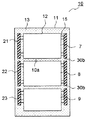
以下に本発明の実施形態を図面を参照して説明する。図1、図2は第1実施形態の冷蔵庫の断熱箱体の正面断面図及び上面断面図を示している。説明の便宜上、前述の図9に示す従来例と同様の部分には同一の符号を付している。 Embodiments of the present invention will be described below with reference to the drawings. 1 and 2 show a front sectional view and a top sectional view of a heat insulating box of the refrigerator according to the first embodiment. For convenience of explanation, the same reference numerals are given to the same parts as those in the conventional example shown in FIG.
冷蔵庫の断熱箱体10は前面が開口する箱状を成している。断熱箱体10の外面は外箱11により形成され、内面は内箱12により形成される。外箱11は鉄板等の金属板から成る側面板11a、背面板11b及び底面板11c(図4参照)を接合して形成される。側面板11aは金属板を折曲して外箱11の天面及び両側面を形成する。
The
内箱12は樹脂成形品から成り、断熱箱体10と一体の断熱壁10aを形成する。断熱壁10aにより前面を開口した複数の貯蔵室7、8、9が区分けして形成される。貯蔵室7、8、9はそれぞれ冷蔵室、冷凍室、野菜室から成っている。外箱11と内箱12との間には真空断熱パネル21、22、23が配され、発泡ウレタン等の発泡断熱材13が充填されている。
The
真空断熱パネル21、22、23は断面コ字型に形成され、上下に並設される。貯蔵室7、9の両側面及び背面を覆う真空断熱パネル21、23は外箱11に貼着される。貯蔵室8の両側面及び背面を覆う真空断熱パネル22は内箱11に貼着される。即ち、隣接する真空断熱パネルの一方は外箱11に近接し、他方は内箱に近接する。
The vacuum
真空断熱パネル21、22、23は正面投影において隙間なく上下に並設される。真空断熱パネル21の下端と真空断熱パネル22の上端との間には上下を連通させる隙間30dが形成される。真空断熱パネル22の下端と真空断熱パネル23の上端との間にも同様に上下を連通させる隙間30dが形成される。
The vacuum
また、真空断熱パネル21、22、23の前端は内箱12の前端よりも後方に配置され、真空断熱パネル21、22、23の前面側にそれぞれ隙間30cが形成される。
Further, the front ends of the vacuum
図3は真空断熱パネル21の一部を示す断面図である。真空断熱パネル22、23も真空断熱パネル21と同様に構成される。真空断熱パネル21は袋状の外被材26内にガラス繊維等の芯材25を内包する。外被材26の内部は真空引きにより芯材25がスペーサとなって減圧され、外被材26は端部26aを密着して封止されている。
FIG. 3 is a cross-sectional view showing a part of the vacuum
真空断熱パネル21、22、23は平板状の芯材25を内包して外被材26を封止した後、プレス加工等によって折曲される。これにより、容易に真空断熱パネル21、22、23を断面コ字型に形成することができる。
The vacuum
外被材26は端部が互いに接着される積層フィルム27、28から成っている。積層フィルム27、28は表面保護層27a、28aと接着層27b、28bとが中間層(不図示)を介して積層される。表面保護層27a、28aはナイロン等から成り、最外層に配されて外被材26の表面を保護する。接着層27b、28bは高密度ポリエチレン(HDPE)等から成り、熱溶着により積層フィルム27、28の端部を密着させる。
The
中間層は第1、第2バリア層(不図示)を積層して形成される。第1バリア層はエチレンビニルアルコール共重合体(EVOH)から成る基台上にアルミニウム蒸着を施した面にポリ塩化ビニル(PVC)系樹脂をコーティングして形成されている。これにより、二酸化炭素やシクロペンタン等のガスを遮蔽することができる。また、第2バリア層はアルミニウム蒸着を施したポリエステル(PET)から成り、水蒸気等のガスを遮蔽する。これにより高いバリア性が保持されている。 The intermediate layer is formed by laminating first and second barrier layers (not shown). The first barrier layer is formed by coating polyvinyl chloride (PVC) resin on the surface of the base made of ethylene vinyl alcohol copolymer (EVOH) on which aluminum is deposited. Thereby, gas, such as a carbon dioxide and cyclopentane, can be shielded. The second barrier layer is made of polyester (PET) subjected to aluminum vapor deposition and shields gas such as water vapor. Thereby, a high barrier property is maintained.
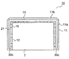
図4は断熱箱体10の組立時の状態を示す分解斜視図である。外箱11の背面側には発泡断熱材13の原液を注入する注入口16が設けられる。注入口16は内箱12に近接する真空断熱パネル22に対向配置される。
FIG. 4 is an exploded perspective view showing a state when the
発泡断熱材13を充填する際には内箱12を前面側が下方になるように設置し、真空断熱パネル22が内箱12上に取り付けられる。また、外箱11の内面には真空断熱パネル21、23が所定位置に取り付けられる。
When filling the foam
そして、内箱12の上方から外箱11を被せ、発泡断熱材13の原液を吐出するノズル17を注入口16に挿入して原液が注入される。この時、注入口16が内箱12に近接する真空断熱パネル22に対向するためノズル17が真空断熱パネル22に接触しない。注入口16から注入された発泡断熱材13の原液は真空断熱パネル22の外面側を流通し、隙間30dを介して真空断熱パネル21、23の内面側に導かれる。
Then, the
また、発泡断熱材13の原液は真空断熱パネル21、23の前方の隙間30cを介して真空断熱パネル21、23内面側に行き渡る。発泡断熱材13は反応によって発泡し、内箱12と外箱11の間に充填される。
Moreover, the undiluted | stock solution of the foam
尚、内箱12の天面を覆う平板状の真空断熱パネルを別途設けてもよく、内箱12の底面を覆う真空断熱パネルを設けてもよい。
A flat-plate vacuum heat insulation panel that covers the top surface of the
本実施形態によると、真空断熱パネル21、22、23を内箱12の両側面及び背面を覆うようにコ字型に折曲したので、従来のように断熱箱体10の側面と背面との境界に発泡断熱材13の流路を形成する隙間30a(図9参照)が形成されない。これにより、発泡断熱材13の流路を形成する隙間の体積を削減することができ、真空断熱パネルの被覆率を増加して断熱箱体10及び冷蔵庫の断熱性を向上することができる。
According to the present embodiment, the vacuum
また、隣接する真空断熱パネルの一方を外箱11に近接するとともに他方を内箱12に近接したので、隣接する真空断熱パネルを正面投影において接近して配置できる。これにより、真空断熱パネルの被覆率をより増加して断熱箱体10及び冷蔵庫の断熱性を向上することができる。更に、隣接する真空断熱パネル21、22、23間には上下に連通する隙間30dが形成されるため、発泡断熱材13を容易に流通させることができる。
Further, since one of the adjacent vacuum heat insulation panels is close to the
また、正面投影において隙間なく複数の真空断熱パネル21、22、23を並設したので、真空断熱パネル21、22、23の被覆率をより増加することができる。加えて、外箱11の背面及び側面からそれぞれ垂直な方向に侵入する熱は真空断熱パネル21、22、23により断熱される。
Moreover, since the several vacuum
矢印B(図1参照)に示すように、隙間30dを斜めに通過する熱は真空断熱材21、22、23を通らないが、発泡断熱材13を通過する距離が長くなる。これにより、実質的な断熱厚みが増加して断熱箱体10の断熱性を更に向上することができる。尚、真空断熱パネル21、22、23を正面投影において重なるように配置してもよい。
As shown by the arrow B (see FIG. 1), heat that passes through the
また、冷蔵室や野菜室は冷凍室よりも室内温度が高いため、冷凍室に比して断熱性能が低くてもよい。このため、貯蔵室7、9に配される真空断熱パネル21、23の厚みを貯蔵室8に配される真空断熱パネル22よりも薄くできる。これにより、冷蔵庫のコストをより削減できるとともに、薄い真空断熱パネル21、23を配した貯蔵室7、9を広くして冷蔵庫の容積効率を向上することができる。
Further, since the refrigerator compartment and the vegetable compartment have a higher room temperature than the freezer compartment, the heat insulation performance may be lower than that of the freezer compartment. For this reason, the thickness of the vacuum
また、発泡断熱材13の原液を注入する注入口16を内箱12に近接する真空断熱パネル22に対向配置したので、吐出用のノズル17を真空断熱パネル21、22、23に接触させずに発泡断熱材13の原液を注入することができる。従って、発泡断熱材13の原液が円滑に流動し、ボイド等を防止して発泡断熱材13を均一に充填することができる。
Further, since the
次に、図5、図6は第2実施形態の冷蔵庫の断熱箱体の正面断面図及び上面断面図を示している。説明の便宜上、前述の図1〜図4に示す第1実施形態と同様の部分には同一の符号を付している。本実施形態は断面コ字型の真空断熱パネル21、22、23の配置が第1実施形態と異なっている。その他の部分は第1実施形態と同様である。
Next, FIG. 5, FIG. 6 has shown the front sectional drawing and top sectional drawing of the heat insulation box of the refrigerator of 2nd Embodiment. For convenience of explanation, the same reference numerals are given to the same parts as those in the first embodiment shown in FIGS. This embodiment is different from the first embodiment in the arrangement of the vacuum
真空断熱パネル21、22、23は断面コ字型に形成され、隙間30bを介して上下に並設される。真空断熱パネル21、22、23間の隙間30bは断熱壁10aと同じ高さに設けられ、断熱壁10aの後方及び側方に配置されている。これにより、真空断熱パネル21、22、23はそれぞれ貯蔵室7、8、9の両側面及び背面を覆う。
The vacuum
また、真空断熱パネル21、22、23は内箱12の側面及び背面に固着された支持部材15に貼着され、内箱12及び外箱11から離れて配置されている。
Further, the vacuum
図7は断熱箱体10の組立時の状態を示す分解斜視図である。外箱11の背面側には発泡断熱材13の原液を注入する注入口16が設けられる。注入口16は各真空断熱パネル21、22、23間の隙間30bに対向配置される。
FIG. 7 is an exploded perspective view showing a state when the
発泡断熱材13を充填する際には内箱12を前面側が下方になるように設置し、支持部材15(図1参照)により真空断熱パネル21、22、23が内箱12上に取り付けられる。支持部材15を内箱12に設けることにより、真空断熱パネル21、22、23を容易に設置することができる。
When filling the foam
そして、上方から外箱11を被せ、発泡断熱材13の原液を吐出するノズル17を注入口16に挿入して原液が注入される。この時、注入口16が隙間30bに対向するためノズル17が真空断熱パネル21、22、23に接触しない。注入口16から注入された発泡断熱材13の原液は隙間30bを介して真空断熱パネル21、22、23の内面側及び外面側に導かれる。
Then, the
また、発泡断熱材13の原液は真空断熱パネル21、22、23の前方の隙間30cを介して真空断熱パネル21、22、23内面側及び外面側に行き渡る。発泡断熱材13は反応によって発泡し、内箱12と外箱11の間に充填される。
Moreover, the undiluted | stock solution of the foam
尚、内箱12の天面を覆う平板状の真空断熱パネルを別途設けてもよく、内箱12の底面を覆う真空断熱パネルを設けてもよい。
A flat-plate vacuum heat insulation panel that covers the top surface of the
本実施形態によると、第1実施形態と同様に、真空断熱パネル21、22、23を内箱12の両側面及び背面を覆うようにコ字型に折曲したので、従来のように断熱箱体10の側面と背面との境界に発泡断熱材13の流路を形成する隙間30a(図9参照)が形成されない。これにより、発泡断熱材13の流路を形成する隙間の体積を削減することができ、真空断熱パネルの被覆率を増加して断熱箱体10及び冷蔵庫の断熱性を向上することができる。
According to the present embodiment, as in the first embodiment, the vacuum
尚、大型の冷蔵庫になると真空断熱パネル21、22、23間の隙間30bが水平方向に長くなる。このため、隙間30bの体積が大きく、断熱箱体10全体に対する真空断熱パネルの被覆率が増加されない場合がある。しかしながら、隙間30bが断熱壁10aの後方及び側方に配置されるので、各貯蔵室7、8、9に対する真空断熱パネル21、22、23の被覆率を増加することができる。従って、断熱箱体10及び冷蔵庫の断熱性を向上することができる。更に、真空断熱パネル21、22、23の使用量を削減して冷蔵庫のコストを削減することができる。
In addition, when it becomes a large sized refrigerator, the
また、発泡断熱材13の原液を注入する注入口16を真空断熱パネル21、22、23間の隙間30bに対向配置したので、吐出用のノズル17を真空断熱パネル21、22、23に接触させずに発泡断熱材13の原液を注入することができる。従って、発泡断熱材13の原液が円滑に流動し、ボイド等を防止して発泡断熱材13を均一に充填することができる。
Further, since the
また、支持部材15により真空断熱パネル21、22、23を内箱12及び外箱11から離して配置したので、背面に凹凸のある内箱12や配管が設けられる外箱11と真空断熱パネル21、22、23の間に発泡断熱材13が流通する流路を確保して充填不足による断熱性の低下を防止することができる。
Further, since the vacuum
尚、凹凸が形成される内箱12の背面側の大きな面積を占める平面と真空断熱パネル21、22、23との距離を、外箱11と真空断熱パネル21、22との距離よりも大きくするとより望ましい。これにより、内箱12の背面側の凸部と真空断熱パネル21、22、23との間に発泡断熱材13が流通する流路をより確実に確保することができる。従って、ボイド等を防止して断熱性の低下を更に防止することができる。
In addition, if the distance between the plane occupying a large area on the back side of the
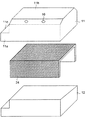
次に、図8は第3実施形態の冷蔵庫の断熱箱体を示す分解斜視図である。説明の便宜上、前述の図5〜図7に示す第2実施形態と同様の部分には同一の符号を付している。本実施形態の断熱箱体10の内箱12と外箱11との間には内箱12の両側面及び背面を覆う断面コ字型の一の真空断熱パネル24が設けられる。その他の部分は第2実施形態と同様である。
Next, FIG. 8 is an exploded perspective view showing the heat insulation box of the refrigerator of the third embodiment. For convenience of explanation, the same reference numerals are given to the same parts as those of the second embodiment shown in FIGS. Between the
真空断熱パネル24は内箱12に設けた支持部材15によって支持され、内箱12及び外箱11から離れて配置されている。尚、内箱12の天面や底面を覆う真空断熱パネルを別途設けてもよい。
The vacuum
本実施形態によると第1、第2実施形態と同様に、真空断熱パネル24を内箱12の隣接する両側面及び背面を覆うようにコ字型に折曲したので、従来のように断熱箱体10の側面と背面との境界に発泡断熱材13の流路を形成する隙間30a(図9参照)が形成されない。これにより、発泡断熱材13の流路を形成する隙間の体積を削減することができ、真空断熱パネルの被覆率を増加して断熱箱体10及び冷蔵庫の断熱性を向上することができる。
According to the present embodiment, as in the first and second embodiments, the vacuum
更に、第2実施形態の隙間30b(図5参照)が形成されず、真空断熱パネルの被覆率をより増加させることができる。
Furthermore, the
第1〜第3実施形態において内箱12の両側面及び背面を3枚及び1枚の真空断熱パネルにより覆っているが、これらの枚数に限られない。
In the first to third embodiments, the both side surfaces and the back surface of the
本発明によると、断熱箱体内に真空断熱パネルを備えた冷蔵庫に利用することができる。 According to this invention, it can utilize for the refrigerator provided with the vacuum heat insulation panel in the heat insulation box.
6、7、8、9 貯蔵室
10 断熱箱体
10a 断熱壁
11 外箱
12 内箱
13 発泡断熱材
15 支持部材
16 注入口
17 ノズル
20、21、22、23、24 真空断熱パネル
25 芯材
26 外被材
30a、30b、30c、30d 隙間
6, 7, 8, 9
Claims (10)
Priority Applications (1)
| Application Number | Priority Date | Filing Date | Title |
|---|---|---|---|
| JP2007292785A JP2009121697A (en) | 2007-11-12 | 2007-11-12 | Refrigerator |
Applications Claiming Priority (1)
| Application Number | Priority Date | Filing Date | Title |
|---|---|---|---|
| JP2007292785A JP2009121697A (en) | 2007-11-12 | 2007-11-12 | Refrigerator |
Publications (2)
| Publication Number | Publication Date |
|---|---|
| JP2009121697A true JP2009121697A (en) | 2009-06-04 |
| JP2009121697A5 JP2009121697A5 (en) | 2010-08-12 |
Family
ID=40814031
Family Applications (1)
| Application Number | Title | Priority Date | Filing Date |
|---|---|---|---|
| JP2007292785A Pending JP2009121697A (en) | 2007-11-12 | 2007-11-12 | Refrigerator |
Country Status (1)
| Country | Link |
|---|---|
| JP (1) | JP2009121697A (en) |
Cited By (13)
| Publication number | Priority date | Publication date | Assignee | Title |
|---|---|---|---|---|
| CN102455106A (en) * | 2010-10-15 | 2012-05-16 | 株式会社东芝 | Refrigerator |
| JP2012112611A (en) * | 2010-11-26 | 2012-06-14 | Panasonic Corp | Heat insulation box body and refrigerator |
| WO2014021018A1 (en) * | 2012-07-30 | 2014-02-06 | シャープ株式会社 | Manufacturing method for insulating boxes, insulating boxes, and refrigerators |
| JP2014055720A (en) * | 2012-09-13 | 2014-03-27 | Sharp Corp | Refrigerator and manufacturing process of refrigerator |
| JP2014070738A (en) * | 2012-09-27 | 2014-04-21 | Toshiba Corp | Heat insulating housing for refrigerator |
| JP2014219172A (en) * | 2013-05-10 | 2014-11-20 | 株式会社東芝 | Refrigerator |
| JP2015068587A (en) * | 2013-09-30 | 2015-04-13 | 日立アプライアンス株式会社 | Hot water storage tank unit |
| JPWO2013146286A1 (en) * | 2012-03-26 | 2015-12-10 | 三菱電機株式会社 | Insulated box, refrigerator and hot water storage device provided with the insulated box |
| WO2016135902A1 (en) * | 2015-02-25 | 2016-09-01 | 三菱電機株式会社 | Refrigerator |
| CN110411091A (en) * | 2019-07-31 | 2019-11-05 | 重庆复升冷鲜香科技有限公司 | The bending technique of car refrigerator and its vacuum heat-insulating plate with bending vacuum heat-insulating plate |
| WO2020144956A1 (en) * | 2019-01-07 | 2020-07-16 | 東芝ライフスタイル株式会社 | Refrigerator |
| CN113474602A (en) * | 2018-12-27 | 2021-10-01 | 青岛海尔电冰箱有限公司 | Refrigerator with a door |
| JP2022031524A (en) * | 2013-06-25 | 2022-02-18 | 東芝ライフスタイル株式会社 | refrigerator |
Citations (4)
| Publication number | Priority date | Publication date | Assignee | Title |
|---|---|---|---|---|
| JP2003014368A (en) * | 2001-06-28 | 2003-01-15 | Matsushita Refrig Co Ltd | Refrigerator |
| JP2005299972A (en) * | 2004-04-08 | 2005-10-27 | Sanyo Electric Co Ltd | Refrigerator |
| JP2006242439A (en) * | 2005-03-02 | 2006-09-14 | Hitachi Home & Life Solutions Inc | Refrigerator and its manufacturing method |
| JP2007285496A (en) * | 2006-04-20 | 2007-11-01 | Hitachi Appliances Inc | Vacuum heat insulating material, and refrigerator and vehicle using the same |
-
2007
- 2007-11-12 JP JP2007292785A patent/JP2009121697A/en active Pending
Patent Citations (4)
| Publication number | Priority date | Publication date | Assignee | Title |
|---|---|---|---|---|
| JP2003014368A (en) * | 2001-06-28 | 2003-01-15 | Matsushita Refrig Co Ltd | Refrigerator |
| JP2005299972A (en) * | 2004-04-08 | 2005-10-27 | Sanyo Electric Co Ltd | Refrigerator |
| JP2006242439A (en) * | 2005-03-02 | 2006-09-14 | Hitachi Home & Life Solutions Inc | Refrigerator and its manufacturing method |
| JP2007285496A (en) * | 2006-04-20 | 2007-11-01 | Hitachi Appliances Inc | Vacuum heat insulating material, and refrigerator and vehicle using the same |
Cited By (16)
| Publication number | Priority date | Publication date | Assignee | Title |
|---|---|---|---|---|
| CN102455106A (en) * | 2010-10-15 | 2012-05-16 | 株式会社东芝 | Refrigerator |
| JP2012112611A (en) * | 2010-11-26 | 2012-06-14 | Panasonic Corp | Heat insulation box body and refrigerator |
| JPWO2013146286A1 (en) * | 2012-03-26 | 2015-12-10 | 三菱電機株式会社 | Insulated box, refrigerator and hot water storage device provided with the insulated box |
| WO2014021018A1 (en) * | 2012-07-30 | 2014-02-06 | シャープ株式会社 | Manufacturing method for insulating boxes, insulating boxes, and refrigerators |
| JP2014055720A (en) * | 2012-09-13 | 2014-03-27 | Sharp Corp | Refrigerator and manufacturing process of refrigerator |
| JP2014070738A (en) * | 2012-09-27 | 2014-04-21 | Toshiba Corp | Heat insulating housing for refrigerator |
| JP2014219172A (en) * | 2013-05-10 | 2014-11-20 | 株式会社東芝 | Refrigerator |
| JP2022031524A (en) * | 2013-06-25 | 2022-02-18 | 東芝ライフスタイル株式会社 | refrigerator |
| JP7422724B2 (en) | 2013-06-25 | 2024-01-26 | 東芝ライフスタイル株式会社 | refrigerator |
| JP2015068587A (en) * | 2013-09-30 | 2015-04-13 | 日立アプライアンス株式会社 | Hot water storage tank unit |
| WO2016135902A1 (en) * | 2015-02-25 | 2016-09-01 | 三菱電機株式会社 | Refrigerator |
| CN113474602A (en) * | 2018-12-27 | 2021-10-01 | 青岛海尔电冰箱有限公司 | Refrigerator with a door |
| JP2020109339A (en) * | 2019-01-07 | 2020-07-16 | 東芝ライフスタイル株式会社 | refrigerator |
| WO2020144956A1 (en) * | 2019-01-07 | 2020-07-16 | 東芝ライフスタイル株式会社 | Refrigerator |
| JP7249782B2 (en) | 2019-01-07 | 2023-03-31 | 東芝ライフスタイル株式会社 | refrigerator |
| CN110411091A (en) * | 2019-07-31 | 2019-11-05 | 重庆复升冷鲜香科技有限公司 | The bending technique of car refrigerator and its vacuum heat-insulating plate with bending vacuum heat-insulating plate |
Similar Documents
| Publication | Publication Date | Title |
|---|---|---|
| JP2009121697A (en) | Refrigerator | |
| JP2009162402A (en) | Refrigerator | |
| JP5198504B2 (en) | Vacuum insulation panel for refrigerator and refrigerator using the same | |
| EP3330650B1 (en) | Refrigerator | |
| CN102452522B (en) | Heat insulation box body | |
| JP2009121694A (en) | Refrigerator | |
| JP4695663B2 (en) | refrigerator | |
| US20160258671A1 (en) | Gas barrier for vacuum insulation | |
| JP2010145001A (en) | Heat insulating case body for refrigerator | |
| KR101495127B1 (en) | Vacuum heat insulation member and refrigerator using same | |
| JP2010276309A (en) | Heat insulation box and refrigerator equipped with the same | |
| CN101846431B (en) | Refrigerator | |
| JP2017511445A (en) | Vacuum insulation material and refrigerator including the same | |
| JP2009121697A5 (en) | ||
| JP2010276308A (en) | Refrigerator having vacuum heat insulating material | |
| JP5401258B2 (en) | refrigerator | |
| JP2013249973A (en) | Refrigerator | |
| JP2011099566A (en) | Vacuum heat insulating panel and refrigerator | |
| JP5985273B2 (en) | Heat insulation box | |
| JP6117544B2 (en) | refrigerator | |
| JP4685828B2 (en) | refrigerator | |
| JP2014052124A (en) | Heat insulating housing | |
| CN102661648A (en) | Refrigerator | |
| JP6811374B2 (en) | Vacuum heat insulating material and refrigerator | |
| JP2013024440A (en) | Refrigerator |
Legal Events
| Date | Code | Title | Description |
|---|---|---|---|
| A521 | Written amendment |
Free format text: JAPANESE INTERMEDIATE CODE: A523 Effective date: 20100624 |
|
| A621 | Written request for application examination |
Free format text: JAPANESE INTERMEDIATE CODE: A621 Effective date: 20100624 |
|
| A977 | Report on retrieval |
Free format text: JAPANESE INTERMEDIATE CODE: A971007 Effective date: 20120224 |
|
| A131 | Notification of reasons for refusal |
Free format text: JAPANESE INTERMEDIATE CODE: A131 Effective date: 20120228 |
|
| A521 | Written amendment |
Free format text: JAPANESE INTERMEDIATE CODE: A523 Effective date: 20120420 |
|
| A02 | Decision of refusal |
Free format text: JAPANESE INTERMEDIATE CODE: A02 Effective date: 20121023 |