JP2009182017A - トラップ装置及びリフロー炉 - Google Patents
トラップ装置及びリフロー炉 Download PDFInfo
- Publication number
- JP2009182017A JP2009182017A JP2008017572A JP2008017572A JP2009182017A JP 2009182017 A JP2009182017 A JP 2009182017A JP 2008017572 A JP2008017572 A JP 2008017572A JP 2008017572 A JP2008017572 A JP 2008017572A JP 2009182017 A JP2009182017 A JP 2009182017A
- Authority
- JP
- Japan
- Prior art keywords
- casing
- trap device
- flux
- exhaust pipe
- support shaft
- Prior art date
- Legal status (The legal status is an assumption and is not a legal conclusion. Google has not performed a legal analysis and makes no representation as to the accuracy of the status listed.)
- Granted
Links
- 230000004907 flux Effects 0.000 claims abstract description 63
- 125000006850 spacer group Chemical group 0.000 claims abstract description 28
- 238000011144 upstream manufacturing Methods 0.000 claims abstract description 14
- 238000010438 heat treatment Methods 0.000 claims description 30
- 239000000758 substrate Substances 0.000 claims description 18
- 238000001816 cooling Methods 0.000 claims description 15
- 239000000463 material Substances 0.000 claims description 12
- 230000004323 axial length Effects 0.000 claims description 8
- 238000007599 discharging Methods 0.000 claims description 4
- 239000004020 conductor Substances 0.000 claims description 3
- 230000008016 vaporization Effects 0.000 claims 1
- 238000004140 cleaning Methods 0.000 description 5
- 238000012423 maintenance Methods 0.000 description 5
- 230000032258 transport Effects 0.000 description 4
- 239000002826 coolant Substances 0.000 description 2
- 239000000498 cooling water Substances 0.000 description 2
- 238000003780 insertion Methods 0.000 description 2
- 230000037431 insertion Effects 0.000 description 2
- 230000002093 peripheral effect Effects 0.000 description 2
- RYGMFSIKBFXOCR-UHFFFAOYSA-N Copper Chemical compound [Cu] RYGMFSIKBFXOCR-UHFFFAOYSA-N 0.000 description 1
- BQCADISMDOOEFD-UHFFFAOYSA-N Silver Chemical compound [Ag] BQCADISMDOOEFD-UHFFFAOYSA-N 0.000 description 1
- 239000000956 alloy Substances 0.000 description 1
- 229910045601 alloy Inorganic materials 0.000 description 1
- XAGFODPZIPBFFR-UHFFFAOYSA-N aluminium Chemical compound [Al] XAGFODPZIPBFFR-UHFFFAOYSA-N 0.000 description 1
- 229910052782 aluminium Inorganic materials 0.000 description 1
- 230000008859 change Effects 0.000 description 1
- 229910052802 copper Inorganic materials 0.000 description 1
- 239000010949 copper Substances 0.000 description 1
- 238000010586 diagram Methods 0.000 description 1
- 230000007613 environmental effect Effects 0.000 description 1
- 239000011521 glass Substances 0.000 description 1
- 238000002955 isolation Methods 0.000 description 1
- 230000009467 reduction Effects 0.000 description 1
- 238000007789 sealing Methods 0.000 description 1
- 238000000926 separation method Methods 0.000 description 1
- 229910052709 silver Inorganic materials 0.000 description 1
- 239000004332 silver Substances 0.000 description 1
- 238000007711 solidification Methods 0.000 description 1
- 230000008023 solidification Effects 0.000 description 1
- 238000009423 ventilation Methods 0.000 description 1
Images


Abstract
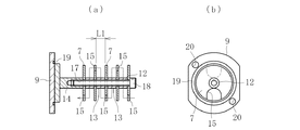
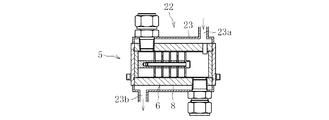
【解決手段】排気管2内を通過する高温ガス中のフラックスを除去するためのトラップ装置である。このトラップ装置は、前記排気管2に付設したバルブ4の上流側に配設されたケーシング本体8及び前記ケーシング本体8に着脱可能に配設した蓋体9を有するケーシング6と、前記蓋体9に付設すると共に前記ケーシング本体8内に配設した支軸12と、前記支軸12に対し挿脱可能に取り付けられると共に前記ケーシング本体8内に蛇行状流路を形成する複数の干渉板7と、前記干渉板7の相互間に介在すると共に前記支軸12に挿脱可能に取り付けられた筒状のスペーサ部材13とを備える。
【選択図】図2
Description
図8に示すように、リフロー炉は、電子部品を接合材を介して搭載した基板100(以下、電子部品搭載基板という)を加熱する加熱室400を備える。一般に、加熱室400内には、前記電子部品搭載基板100を搬送する搬送手段200と、搬送される電子部品搭載基板100を加熱する加熱手段300が配設されている。加熱室400内で電子部品搭載基板100を加熱することにより、接合材に含有されるフラックスを気化させて電子部品と基板との接合を行う。
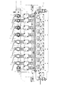
図1は本発明のトラップ装置を備えたリフロー炉の正面図である。図1に示すように、リフロー炉は、加熱室1と排気管2を備える。加熱室1内には、上記従来の構成と同様に、電子部品搭載基板を搬送する搬送手段と、搬送される電子部品搭載基板を加熱する加熱手段が配設されている(図示省略)。
加熱室1内において、電子部品搭載基板を搬送しつつ加熱する。この加熱によって、接合材に含有されるフラックスが気化され、これにより電子部品と基板が接合される。加熱室1内の高温ガスは、排気管2の複数の枝管3を通して外部へ排出される。なお、予めバルブ4を操作して枝管3の排気流量を調節することによって、加熱室1内の温度を調整している。
2 排気管
4 バルブ
5 トラップ装置
6 ケーシング
7 干渉板
8 ケーシング本体
9 蓋体
12 支軸
13 スペーサ部材
21 窓部
22 冷却手段
Claims (8)
- 排気管内を通過する高温ガス中のフラックスを除去するためのトラップ装置であって、
前記排気管に付設したバルブの上流側に配設されたことを特徴とするトラップ装置。 - 排気管内を通過する高温ガス中のフラックスを除去するためのトラップ装置であって、
前記排気管に付設したバルブの上流側に配設されたケーシング本体及び前記ケーシング本体に着脱可能に配設した蓋体を有するケーシングと、前記蓋体に付設すると共に前記ケーシング本体内に配設した支軸と、前記支軸に対し挿脱可能に取り付けられると共に前記ケーシング本体内に蛇行状流路を形成する複数の干渉板と、前記干渉板の相互間に介在すると共に前記支軸に挿脱可能に取り付けられた筒状のスペーサ部材とを備えたことを特徴とするトラップ装置。 - 軸方向長さの異なる前記スペーサ部材を複数種類備えた請求項2に記載のトラップ装置。
- 前記ケーシングに透明部材から成る窓部を設けた請求項2又は3に記載のトラップ装置。
- 前記ケーシングと前記干渉板の少なくとも一方を冷却する冷却手段を設けた請求項2から4のいずれか1項に記載のトラップ装置。
- 前記ケーシングと前記干渉板の少なくとも一方を熱良導体にて構成した請求項2から5のいずれか1項に記載のトラップ装置。
- 基板に接合材を介して電子部品を搭載して成る電子部品搭載基板を加熱することにより前記接合材に含有されるフラックスを気化させて前記電子部品と前記基板とを接合する加熱室と、前記気化したフラックスが混在する高温ガスを前記加熱室内から排出するための排気管と、前記排気管の排気流量を調節するバルブとを備えたリフロー炉において、
前記排気管の前記バルブの上流側に、前記高温ガスに混在するフラックスを除去するためのトラップ装置を配設したことを特徴とするリフロー炉。 - 前記トラップ装置は、前記排気管に配設したケーシング本体及び前記ケーシング本体に着脱可能に配設した蓋体を有するケーシングと、前記蓋体に付設すると共に前記ケーシング本体内に配設した支軸と、前記支軸に対し挿脱可能に取り付けられると共に前記ケーシング本体内に蛇行状流路を形成する複数の干渉板と、前記干渉板の相互間に介在すると共に前記支軸に挿脱可能に取り付けられた筒状のスペーサ部材とを備えた請求項7に記載のリフロー炉。
Priority Applications (1)
| Application Number | Priority Date | Filing Date | Title |
|---|---|---|---|
| JP2008017572A JP5031603B2 (ja) | 2008-01-29 | 2008-01-29 | トラップ装置及びリフロー炉 |
Applications Claiming Priority (1)
| Application Number | Priority Date | Filing Date | Title |
|---|---|---|---|
| JP2008017572A JP5031603B2 (ja) | 2008-01-29 | 2008-01-29 | トラップ装置及びリフロー炉 |
Publications (2)
| Publication Number | Publication Date |
|---|---|
| JP2009182017A true JP2009182017A (ja) | 2009-08-13 |
| JP5031603B2 JP5031603B2 (ja) | 2012-09-19 |
Family
ID=41035782
Family Applications (1)
| Application Number | Title | Priority Date | Filing Date |
|---|---|---|---|
| JP2008017572A Expired - Fee Related JP5031603B2 (ja) | 2008-01-29 | 2008-01-29 | トラップ装置及びリフロー炉 |
Country Status (1)
| Country | Link |
|---|---|
| JP (1) | JP5031603B2 (ja) |
Cited By (3)
| Publication number | Priority date | Publication date | Assignee | Title |
|---|---|---|---|---|
| US20150034700A1 (en) * | 2002-07-01 | 2015-02-05 | Semigear Inc | Reflow treating unit & substrate treating apparatus |
| JP2018122198A (ja) * | 2017-01-30 | 2018-08-09 | パナソニックIpマネジメント株式会社 | フラックス回収装置およびリフロー装置 |
| JP2018122197A (ja) * | 2017-01-30 | 2018-08-09 | パナソニックIpマネジメント株式会社 | フラックス回収装置およびリフロー装置ならびにフラックス回収装置における気体交換方法 |
Citations (4)
| Publication number | Priority date | Publication date | Assignee | Title |
|---|---|---|---|---|
| JPH0413475A (ja) * | 1990-04-27 | 1992-01-17 | Matsushita Electric Ind Co Ltd | 雰囲気炉及び雰囲気炉の雰囲気維持方法 |
| JPH0593079U (ja) * | 1992-02-28 | 1993-12-17 | 光洋リンドバーグ株式会社 | はんだリフロー装置 |
| JPH07202405A (ja) * | 1993-12-28 | 1995-08-04 | Nippon Dennetsu Keiki Kk | はんだ付け装置 |
| JPH09323022A (ja) * | 1996-06-05 | 1997-12-16 | Nitsuku:Kk | フラックスヒューム除去装置 |
-
2008
- 2008-01-29 JP JP2008017572A patent/JP5031603B2/ja not_active Expired - Fee Related
Patent Citations (4)
| Publication number | Priority date | Publication date | Assignee | Title |
|---|---|---|---|---|
| JPH0413475A (ja) * | 1990-04-27 | 1992-01-17 | Matsushita Electric Ind Co Ltd | 雰囲気炉及び雰囲気炉の雰囲気維持方法 |
| JPH0593079U (ja) * | 1992-02-28 | 1993-12-17 | 光洋リンドバーグ株式会社 | はんだリフロー装置 |
| JPH07202405A (ja) * | 1993-12-28 | 1995-08-04 | Nippon Dennetsu Keiki Kk | はんだ付け装置 |
| JPH09323022A (ja) * | 1996-06-05 | 1997-12-16 | Nitsuku:Kk | フラックスヒューム除去装置 |
Cited By (5)
| Publication number | Priority date | Publication date | Assignee | Title |
|---|---|---|---|---|
| US20150034700A1 (en) * | 2002-07-01 | 2015-02-05 | Semigear Inc | Reflow treating unit & substrate treating apparatus |
| US9226407B2 (en) * | 2002-07-01 | 2015-12-29 | Semigear Inc | Reflow treating unit and substrate treating apparatus |
| JP2015032828A (ja) * | 2013-08-01 | 2015-02-16 | ピーエスケー・インコーポレーテッド | リフロ処理ユニット及び基板処理装置 |
| JP2018122198A (ja) * | 2017-01-30 | 2018-08-09 | パナソニックIpマネジメント株式会社 | フラックス回収装置およびリフロー装置 |
| JP2018122197A (ja) * | 2017-01-30 | 2018-08-09 | パナソニックIpマネジメント株式会社 | フラックス回収装置およびリフロー装置ならびにフラックス回収装置における気体交換方法 |
Also Published As
| Publication number | Publication date |
|---|---|
| JP5031603B2 (ja) | 2012-09-19 |
Similar Documents
| Publication | Publication Date | Title |
|---|---|---|
| JP5031603B2 (ja) | トラップ装置及びリフロー炉 | |
| EP1746369A3 (en) | Water removal apparatus and inspection apparatus including same | |
| JP2005140119A (ja) | ノズルセグメントのプラットホーム端縁用の冷却システム | |
| TW200808482A (en) | Reflow furnace | |
| MY125733A (en) | Flux collection method and system | |
| TW200739014A (en) | Heat removing method and heat removing apparatus | |
| TWI818081B (zh) | 廢氣淨化裝置 | |
| US9453680B2 (en) | Injector device for blowing oxygen-rich gases on or in, in a metallurgical unit or melting vessel, and electric arc furnace | |
| JP2008124112A (ja) | リフロー半田付け方法及び装置 | |
| WO2007082676A3 (de) | Vorrichtung zur abgaskühlung | |
| JP2009148816A (ja) | フラックス回収装置 | |
| JP5264079B2 (ja) | 加熱装置 | |
| JP4786595B2 (ja) | リフロー半田付け装置 | |
| WO2020218122A1 (ja) | 加熱装置及びはんだ接合済対象物の製造方法 | |
| JP2883263B2 (ja) | 半田付け装置における排煙装置 | |
| JP6510817B2 (ja) | モータの冷却構造およびこれを備えた溶接トーチユニット | |
| TWI819097B (zh) | 廢氣淨化裝置 | |
| JP2008180453A (ja) | ウォーターサーバー | |
| JP2009190045A (ja) | はんだ付け装置 | |
| JP2004195476A (ja) | はんだ付け用冷却装置およびリフロー装置 | |
| JP2006258348A (ja) | 熱処理装置 | |
| JP2003181682A (ja) | はんだ付け用冷却装置 | |
| JP2009099762A (ja) | リフロー装置、フラックス回収装置およびフラックスの回収方法 | |
| FR3038040A1 (fr) | Echangeur thermique a cartouche de-ionisante | |
| JP2008221329A (ja) | 加熱装置 |
Legal Events
| Date | Code | Title | Description |
|---|---|---|---|
| A621 | Written request for application examination |
Free format text: JAPANESE INTERMEDIATE CODE: A621 Effective date: 20110111 |
|
| A977 | Report on retrieval |
Free format text: JAPANESE INTERMEDIATE CODE: A971007 Effective date: 20120327 |
|
| A131 | Notification of reasons for refusal |
Free format text: JAPANESE INTERMEDIATE CODE: A131 Effective date: 20120330 |
|
| A521 | Request for written amendment filed |
Free format text: JAPANESE INTERMEDIATE CODE: A523 Effective date: 20120524 |
|
| TRDD | Decision of grant or rejection written | ||
| A01 | Written decision to grant a patent or to grant a registration (utility model) |
Free format text: JAPANESE INTERMEDIATE CODE: A01 Effective date: 20120611 |
|
| A01 | Written decision to grant a patent or to grant a registration (utility model) |
Free format text: JAPANESE INTERMEDIATE CODE: A01 |
|
| A61 | First payment of annual fees (during grant procedure) |
Free format text: JAPANESE INTERMEDIATE CODE: A61 Effective date: 20120627 |
|
| R150 | Certificate of patent or registration of utility model |
Ref document number: 5031603 Country of ref document: JP Free format text: JAPANESE INTERMEDIATE CODE: R150 Free format text: JAPANESE INTERMEDIATE CODE: R150 |
|
| FPAY | Renewal fee payment (event date is renewal date of database) |
Free format text: PAYMENT UNTIL: 20150706 Year of fee payment: 3 |
|
| R250 | Receipt of annual fees |
Free format text: JAPANESE INTERMEDIATE CODE: R250 |
|
| R250 | Receipt of annual fees |
Free format text: JAPANESE INTERMEDIATE CODE: R250 |
|
| R250 | Receipt of annual fees |
Free format text: JAPANESE INTERMEDIATE CODE: R250 |
|
| R250 | Receipt of annual fees |
Free format text: JAPANESE INTERMEDIATE CODE: R250 |
|
| R250 | Receipt of annual fees |
Free format text: JAPANESE INTERMEDIATE CODE: R250 |
|
| R250 | Receipt of annual fees |
Free format text: JAPANESE INTERMEDIATE CODE: R250 |
|
| R250 | Receipt of annual fees |
Free format text: JAPANESE INTERMEDIATE CODE: R250 |
|
| R250 | Receipt of annual fees |
Free format text: JAPANESE INTERMEDIATE CODE: R250 |
|
| LAPS | Cancellation because of no payment of annual fees |