JP2006324327A - Substrate storage container and manufacturing method thereof - Google Patents
Substrate storage container and manufacturing method thereof Download PDFInfo
- Publication number
- JP2006324327A JP2006324327A JP2005144137A JP2005144137A JP2006324327A JP 2006324327 A JP2006324327 A JP 2006324327A JP 2005144137 A JP2005144137 A JP 2005144137A JP 2005144137 A JP2005144137 A JP 2005144137A JP 2006324327 A JP2006324327 A JP 2006324327A
- Authority
- JP
- Japan
- Prior art keywords
- substrate
- support pieces
- container
- container body
- side walls
- Prior art date
- Legal status (The legal status is an assumption and is not a legal conclusion. Google has not performed a legal analysis and makes no representation as to the accuracy of the status listed.)
- Granted
Links
Images

Classifications
-
- H—ELECTRICITY
- H10—SEMICONDUCTOR DEVICES; ELECTRIC SOLID-STATE DEVICES NOT OTHERWISE PROVIDED FOR
- H10P—GENERIC PROCESSES OR APPARATUS FOR THE MANUFACTURE OR TREATMENT OF DEVICES COVERED BY CLASS H10
- H10P95/00—Generic processes or apparatus for manufacture or treatments not covered by the other groups of this subclass
-
- H—ELECTRICITY
- H10—SEMICONDUCTOR DEVICES; ELECTRIC SOLID-STATE DEVICES NOT OTHERWISE PROVIDED FOR
- H10P—GENERIC PROCESSES OR APPARATUS FOR THE MANUFACTURE OR TREATMENT OF DEVICES COVERED BY CLASS H10
- H10P72/00—Handling or holding of wafers, substrates or devices during manufacture or treatment thereof
- H10P72/10—Handling or holding of wafers, substrates or devices during manufacture or treatment thereof using carriers specially adapted therefor, e.g. front opening unified pods [FOUP]
- H10P72/19—Handling or holding of wafers, substrates or devices during manufacture or treatment thereof using carriers specially adapted therefor, e.g. front opening unified pods [FOUP] closed carriers
- H10P72/1911—Handling or holding of wafers, substrates or devices during manufacture or treatment thereof using carriers specially adapted therefor, e.g. front opening unified pods [FOUP] closed carriers characterised by materials, roughness, coatings or the like
- H10P72/1912—Handling or holding of wafers, substrates or devices during manufacture or treatment thereof using carriers specially adapted therefor, e.g. front opening unified pods [FOUP] closed carriers characterised by materials, roughness, coatings or the like characterised by shock absorbing elements, e.g. retainers or cushions
-
- H—ELECTRICITY
- H10—SEMICONDUCTOR DEVICES; ELECTRIC SOLID-STATE DEVICES NOT OTHERWISE PROVIDED FOR
- H10P—GENERIC PROCESSES OR APPARATUS FOR THE MANUFACTURE OR TREATMENT OF DEVICES COVERED BY CLASS H10
- H10P72/00—Handling or holding of wafers, substrates or devices during manufacture or treatment thereof
- H10P72/10—Handling or holding of wafers, substrates or devices during manufacture or treatment thereof using carriers specially adapted therefor, e.g. front opening unified pods [FOUP]
- H10P72/19—Handling or holding of wafers, substrates or devices during manufacture or treatment thereof using carriers specially adapted therefor, e.g. front opening unified pods [FOUP] closed carriers
- H10P72/1921—Handling or holding of wafers, substrates or devices during manufacture or treatment thereof using carriers specially adapted therefor, e.g. front opening unified pods [FOUP] closed carriers characterised by substrate supports
Landscapes
- Packaging Frangible Articles (AREA)
- Container, Conveyance, Adherence, Positioning, Of Wafer (AREA)
- Injection Moulding Of Plastics Or The Like (AREA)
- Details Of Rigid Or Semi-Rigid Containers (AREA)
Abstract
【課題】 基板と支持片が擦れて基板が損傷したり、塵埃が発生するのを防ぎ、基板の周縁部や裏面が汚れたり、傷付くのを抑制できる基板収納容器及びその製造方法を提供する。
【解決手段】 複数枚の基板Wを整列収納する容器本体1と、容器本体1を形成する一対の側壁内面にそれぞれ配設されて容器本体1の正面側に位置し、基板Wの側部周縁を支持する第一の支持片20と、容器本体1を形成する一対の側壁内面にそれぞれ配設されて容器本体1の背面壁側に位置し、基板Wの側部周縁を支持する第二の支持片24とを備える。そして、基板Wの側部周縁と接触する各側壁4の接触部5、第一の支持片20、及び第二の支持片24を容器本体1よりも低摩擦性の樹脂層30で被覆する。
【選択図】 図3PROBLEM TO BE SOLVED: To provide a substrate storage container and its manufacturing method capable of preventing the substrate and supporting pieces from rubbing and damaging the substrate and generating dust and preventing the peripheral edge and back surface of the substrate from becoming dirty or damaged. .
SOLUTION: A container main body 1 for arranging and storing a plurality of substrates W and a pair of side wall inner surfaces forming the container main body 1 are disposed on the front side of the container main body 1, and the peripheral edges of the side of the substrate W are provided. And a second support member that is disposed on the inner surface of the pair of side walls forming the container body 1 and is located on the back wall side of the container body 1 and supports the peripheral edge of the side of the substrate W. And a support piece 24. Then, the contact portion 5 of each side wall 4 that contacts the peripheral edge of the substrate W, the first support piece 20, and the second support piece 24 are covered with a resin layer 30 having a lower friction than the container body 1.
[Selection] Figure 3
Description
本発明は、各種の半導体ウェーハ、フォトマスクガラス、あるいはアルミディスク等からなる基板を収納する基板収納容器及びその製造方法に関するものである。 The present invention relates to a substrate storage container for storing substrates made of various semiconductor wafers, photomask glass, aluminum disks, and the like, and a method for manufacturing the same.
従来の基板収納容器は、図示しないが、半導体ウェーハからなる複数枚の基板を整列収納する容器本体と、この容器本体の開口部である正面を開閉する着脱自在の蓋体と、容器本体の正面を覆う蓋体を固定する係止機構とを備えて構成され、精密基板収納容器として利用される。容器本体の両側壁の内面には、基板の側部周縁を水平に支持する平面略く字形の支持片がそれぞれ複数配設され、蓋体の内面には、基板の前部周縁を保持するフロントリテーナが装着されている。 Although not shown, a conventional substrate storage container includes a container body for aligning and storing a plurality of substrates made of semiconductor wafers, a detachable lid that opens and closes a front surface that is an opening of the container body, and a front surface of the container body. And a locking mechanism for fixing the lid that covers the cover, and is used as a precision substrate storage container. A plurality of flat, substantially U-shaped support pieces for horizontally supporting the peripheral edge of the substrate are disposed on the inner surfaces of both side walls of the container body, and the front surface for holding the front periphery of the substrate is provided on the inner surface of the lid. A retainer is installed.
このような基板収納容器は、基板の生産工場から加工工場まで基板を安全に輸送するために使用され、加工工場で基板に各種の処理が施されることにより、半導体部品の加工用部材や半導体部品が生産される(特許文献1、2参照)。
従来の基板収納容器は、以上のように構成され、自動車、航空機、船舶等による輸送時や積み替え作業時に衝撃を受けやすく、衝撃を受けると、基板と支持片とが擦れて基板が損傷したり、パーティクル(particulate)が発生して基板の表面に付着し、製品の機能や歩留まりの低下を招くという大きな問題がある。特に、近年の半導体部品の電子回路は益々狭ピッチ化されてきているので、パーティクル等による汚染は深刻な問題となる。 Conventional substrate storage containers are configured as described above, and are susceptible to impact during transportation by automobiles, airplanes, ships, etc., and transshipment work. When impact is received, the substrate and support pieces are rubbed and the substrate is damaged. There is a big problem that particles (particulates) are generated and adhere to the surface of the substrate, resulting in a decrease in product function and yield. In particular, since electronic circuits for semiconductor components in recent years have been increasingly narrowed, contamination by particles or the like becomes a serious problem.
また、基板の周縁部から半径内方向に3mmの領域は、従来、半導体部品の加工に使用しない排他領域とされてきたが、近年、電子回路の狭ピッチ化や製品の小型化の観点から、排他領域を狭くして歩留まりを向上させたいという要望がある。このような要望を満たすためには、基板の周縁部や裏面が汚れたり、傷付くのを防止する必要がある。 In addition, a region of 3 mm in the radial inward direction from the peripheral edge of the substrate has been conventionally used as an exclusive region that is not used for processing semiconductor components, but in recent years, from the viewpoint of narrowing the pitch of electronic circuits and downsizing of products, There is a demand to improve the yield by narrowing the exclusive area. In order to satisfy such a demand, it is necessary to prevent the peripheral edge and back surface of the substrate from becoming dirty or damaged.
本発明は上記に鑑みなされたもので、基板と支持片とが擦れて基板が損傷したり、塵埃が発生するのを防ぎ、基板の周縁部や裏面が汚れたり、傷付くのを抑制することのできる基板収納容器及びその製造方法を提供することを目的としている。 The present invention has been made in view of the above, and prevents the substrate and the support piece from rubbing to damage the substrate and the generation of dust, and suppresses the peripheral edge and back surface of the substrate from being stained or damaged. It is an object of the present invention to provide a substrate storage container that can be used and a method for manufacturing the same.
本発明においては上記課題を解決するため、容器本体に基板を収納するものであって、容器本体を形成する一対の側壁にそれぞれ設けられて容器本体の開口部側に位置し、基板の周縁部を支持する第一の支持片と、容器本体を形成する一対の側壁にそれぞれ設けられて容器本体の奥の壁側に位置し、基板の周縁部を支持する第二の支持片とを含み、
基板の周縁部と接触する各側壁の接触部、第一の支持片、及び第二の支持片のうち、少なくとも第一、第二の支持片を容器本体よりも低摩擦性の樹脂層で被覆したことを特徴としている。
In the present invention, in order to solve the above problems, a substrate is accommodated in a container body, provided on each of a pair of side walls forming the container body and positioned on the opening side of the container body, and a peripheral portion of the substrate A first support piece for supporting the substrate, and a second support piece provided on each of the pair of side walls forming the container body and positioned on the back wall side of the container body to support the peripheral edge of the substrate,
At least the first and second support pieces of the contact portions of the side walls, the first support pieces, and the second support pieces that are in contact with the peripheral edge of the substrate are covered with a resin layer having a lower friction than the container body. It is characterized by that.
なお、容器本体の奥の壁に、基板の周縁部を支持する弾性のリテーナを設けることができる。
また、容器本体を形成する一対の側壁から第一、第二の支持片をそれぞれ個別に突出させ、これら第一、第二の支持片の間に空隙を形成することができる。
An elastic retainer that supports the peripheral edge of the substrate can be provided on the inner wall of the container body.
Further, the first and second support pieces can be individually protruded from the pair of side walls forming the container body, and a gap can be formed between the first and second support pieces.
また、基板の周縁部と接触する各側壁の接触部を、一対の側壁における第一、第二の支持片に基板を支持させた場合に、基板を通る中心線のうち、基板の出し入れ方向と直交する交差線の延長線上に位置する部分とすることもできる。
さらに、容器本体をポリカーボネート、シクロオレフィンポリマー、あるいはポリエーテルイミドを用いて形成し、
低摩擦性の樹脂層を、ポリブチレンテレフタレート又はポリエーテルエーテルケトンとすることが好ましい。
In addition, when the substrate is supported by the first and second support pieces on the pair of side walls, the contact portion of each side wall that comes into contact with the peripheral edge of the substrate, of the center line passing through the substrate, It can also be a part located on the extended line of the orthogonal crossing line.
Furthermore, the container body is formed using polycarbonate, cycloolefin polymer, or polyetherimide,
The low friction resin layer is preferably polybutylene terephthalate or polyether ether ketone.
また、本発明においては上記課題を解決するため、請求項1ないし5いずれかに記載のものの製造方法であって、
一対の側壁に第一、第二の支持片をそれぞれ形成し、基板の周縁部と接触する各側壁の接触部、及び第一、第二の支持片のうち、少なくとも第一、第二の支持片を低摩擦性の樹脂層で被覆し、一対の側壁を容器本体用の成形金型にインサートして容器本体を成形することを特徴としている。
In the present invention, in order to solve the above-mentioned problem,
First and second support pieces are formed on the pair of side walls, respectively, and at least the first and second supports among the contact portions of the side walls that contact the peripheral edge of the substrate and the first and second support pieces. The piece is covered with a low-friction resin layer, and the container body is molded by inserting a pair of side walls into a molding die for the container body.
また、基板を収納する容器本体と、この容器本体の開口部を開閉する蓋体とを備えたものであって、
容器本体を形成する一対の側壁にそれぞれ設けられて容器本体の開口部側に位置し、基板の周縁部を支持する第一の支持片と、容器本体を形成する一対の側壁にそれぞれ設けられて容器本体の奥の壁側に位置し、基板の周縁部を支持する第二の支持片とを含み、
基板の周縁部と接触する各側壁の接触部、第一の支持片、及び第二の支持片のうち、少なくとも第一、第二の支持片を容器本体よりも低摩擦性の樹脂層で被覆し、
蓋体には、基板の周縁部を支持する弾性のリテーナを設けたことを特徴としても良い。
In addition, a container body that stores the substrate, and a lid that opens and closes the opening of the container body,
Provided on each of the pair of side walls forming the container main body and positioned on the opening side of the container main body, and provided on each of the pair of side walls forming the container main body and the first support piece for supporting the peripheral portion of the substrate. A second support piece located on the back wall side of the container body and supporting the peripheral edge of the substrate;
At least the first and second support pieces of the contact portions of the side walls, the first support pieces, and the second support pieces that are in contact with the peripheral edge of the substrate are covered with a resin layer having a lower friction than the container body. And
The lid may be provided with an elastic retainer that supports the peripheral edge of the substrate.
ここで、特許請求の範囲における基板には、少なくとも単数複数の各種半導体ウェーハ(例えば、200mm、300mm、450mmタイプ)、液晶ガラス、フォトマスクガラス、あるいはアルミディスク等の精密基板が含まれる。容器本体は、フロントオープンボックスタイプ、トップオープンボックスタイプ、FOSBタイプ、FOUBタイプ、透明、不透明、半透明、導電性、絶縁性等を特に問うものではない。 Here, the substrate in the claims includes at least one precision substrate such as various semiconductor wafers (for example, 200 mm, 300 mm, 450 mm type), liquid crystal glass, photomask glass, or aluminum disk. The container main body does not specifically ask front open box type, top open box type, FOSB type, FOUB type, transparent, opaque, translucent, conductive, insulating, or the like.
容器本体の奥の壁には、基板の周縁部を支持する弾性のリテーナを備え、このリテーナの少なくとも基板支持部を容器本体よりも低摩擦性の樹脂層で形成することができる。容器本体の天井や周壁には、基板把握用の透視窓を選択的に形成することができる。また、第一、第二の支持片を一体形成し、これら第一、第二の支持片の間を薄肉に形成して基板に接触しないようにすることもできる。さらに、低摩擦性の樹脂層は、ASTM D1894に従って鋼に対する摩擦係数を測定した場合の測定値が0.33未満、好ましくは0.20以下であるのが良い。 The inner wall of the container main body is provided with an elastic retainer that supports the peripheral edge of the substrate, and at least the substrate support portion of the retainer can be formed of a resin layer having a lower friction than the container main body. A see-through window for grasping the substrate can be selectively formed on the ceiling or peripheral wall of the container body. Alternatively, the first and second support pieces may be integrally formed, and the first and second support pieces may be formed thin so as not to contact the substrate. Furthermore, the low-friction resin layer should have a measured value of less than 0.33, preferably 0.20 or less, when the coefficient of friction against steel is measured according to ASTM D1894.
本発明によれば、容器本体の基板と接触する可能性のある部分のうち、少なくとも第一、第二の支持片に、容器本体の材料よりも低摩擦性の樹脂層を嵌合や成形等によりそれぞれ設けて覆うので、例え基板収納容器に衝撃等が作用しても、基板と第一、第二の支持片とが擦れて基板が傷付いたり、塵埃が発生して基板に付着するのを抑制することができる。 According to the present invention, a resin layer having a lower friction than the material of the container body is fitted, molded, or the like on at least the first and second support pieces among the portions that may come into contact with the substrate of the container body. Therefore, even if an impact or the like acts on the substrate storage container, the substrate and the first and second support pieces rub against each other and the substrate may be damaged or dust may be generated and adhere to the substrate. Can be suppressed.
本発明によれば、基板と支持片とが擦れて基板が損傷したり、塵埃が発生するのを防ぐことができるという効果がある。また、基板の周縁部や裏面が汚れたり、傷付くのを抑制することができるという効果がある。
また、容器本体の奥の壁に、基板の周縁部を支持する弾性のリテーナを設ければ、例え移動時に基板収納容器が衝撃を受けても、基板のがたつきを抑えることができる。
According to the present invention, there is an effect that it is possible to prevent the substrate and the support piece from being rubbed to damage the substrate or to generate dust. In addition, there is an effect that it is possible to prevent the peripheral edge and back surface of the substrate from being stained or damaged.
Further, if an elastic retainer that supports the peripheral edge of the substrate is provided on the inner wall of the container main body, even if the substrate storage container receives an impact during movement, it is possible to suppress the rattling of the substrate.
さらに、容器本体の両側壁から第一、第二の支持片をそれぞれ個別に突出させ、これら第一、第二の支持片の間に空隙を形成すれば、第一、第二の支持片の材料使用量を減らしたり、基板との接触領域を減少させ、接触に伴う汚染を低減することができる。 Furthermore, if the first and second support pieces are individually protruded from both side walls of the container body and a gap is formed between the first and second support pieces, the first and second support pieces It is possible to reduce the amount of material used, reduce the contact area with the substrate, and reduce contamination due to contact.
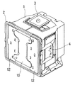
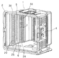
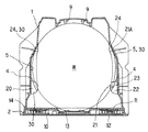
以下、図面を参照して本発明の好ましい実施の形態を説明すると、本実施形態における基板収納容器は、図1ないし図9に示すように、複数枚の基板Wを収納する容器本体1と、この容器本体1の開口部である正面を開閉する蓋体10と、容器本体1を形成する左右一対の側壁4にそれぞれ配設されて容器本体1の正面側に位置する複数の第一の支持片20と、容器本体1を形成する左右一対の側壁4にそれぞれ配設されて容器本体1のリヤ側に位置する複数の第二の支持片24とを備えた輸送用の精密基板収納容器であり、基板Wと接触する各側壁4の接触部5、及び第一、第二の支持片20・24を低摩擦性の樹脂層30で被覆するようにしている。
Hereinafter, a preferred embodiment of the present invention will be described with reference to the drawings. As shown in FIGS. 1 to 9, a substrate storage container in the present embodiment includes a
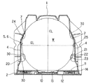
基板Wは、図3に示すように、口径300mmの薄く丸い半導体ウェーハ、具体的にはシリコンウェーハからなり、表裏両面のうち少なくとも表面が鏡面加工され、周縁部には、位置合わせ用のオリフラや平面略半楕円形のノッチが選択的に形成されており、専用のロボットにより出し入れされる。 As shown in FIG. 3, the substrate W is made of a thin and round semiconductor wafer having a diameter of 300 mm, specifically a silicon wafer, and at least the surface of both the front and back surfaces is mirror-finished. A plane substantially semi-elliptical notch is selectively formed, and is taken in and out by a dedicated robot.
容器本体1の両側壁前部と蓋体10の両側部には、容器本体1の正面を嵌合閉鎖する蓋体10を固定する係止機構が配設され、この係止機構は、容器本体1の両側壁前部にそれぞれ突出形成される係止ブロックと、蓋体10の両側部にそれぞれ回転可能に軸支されて係止ブロックに着脱自在に嵌合する一部中空の係止片とから構成される。
A locking mechanism for fixing the
容器本体1は、図1ないし図3に示すように、専用の成形金型に一対の側壁4をインサートして所定の材料を充填するインサート成形により正面の開口した透明のフロントオープンボックスタイプに形成され、複数枚(25枚あるいは26枚)の基板Wを所定のピッチで上下方向に並べて整列収納するよう機能する。
As shown in FIGS. 1 to 3, the
この容器本体1の材料としては、特に限定されるものではないが、例えばポリカーボネート、ポリブチレンテレフタレート、シクロオレフィンポリマー、ポリエーテルイミド、ポリエーテルエーテルケトン等の樹脂、あるいはこれらの樹脂やアロイ樹脂に、カーボン、炭素繊維、カーボンナノチューブ、金属繊維、金属酸化物、導電性高分子等を添加した導電性の樹脂が選択的に使用される。これらの材料の中でも、透明性に優れるポリカーボネートが特に好ましい。
The material of the
容器本体1は、図1ないし図3に示すように、その正面の周縁部が断面略L字形に外方向に屈曲形成されてリム部2を形成し、底面の前部両側と後部中央とには、位置決め用の位置決め具が配設されており、天井の中央部には、自動搬送機に保持されるロボティックフランジ3が着脱自在に装着される。
As shown in FIG. 1 to FIG. 3, the
容器本体1の両側壁4は、図3や図5等に示すように、基板Wの形状に対応するようそれぞれ屈曲形成され、容器本体1の製造前に複数の第一、第二の支持片20・24がそれぞれ成形されており、基板Wの周縁部と接触する接触部5、及び第一、第二の支持片20・24が樹脂層30で被覆された後、容器本体1用の成形金型にインサートされることにより容器本体1の一部を形成する。
Both
蓋体10は、図3に示すように、容器本体1の正面のリム部2に着脱自在に嵌合される断面略皿形の筐体11と、この筐体11の表面に装着されるカバー12とを備え、容器本体1の背面壁内面と対向する筐体11の対向面には、基板Wの前部周縁を保持する弾性のフロントリテーナ13が装着され、筐体11の周壁には、エンドレスのシールガスケット14が嵌合されており、このシールガスケット14が圧縮変形して容器本体1を密封するよう機能する。
As shown in FIG. 3, the
蓋体10は、例えばフッ素を含有したポリカーボネート、ポリカーボネート、ポリエーテルサルフォン、ポリエーテルイミド、ポリエーテルエーテルケトン等の樹脂を用いて成形される。
The
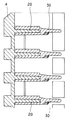
複数の第一、第二の支持片20・24は、図2ないし図5に示すように、容器本体1の両側壁内面から内方向にそれぞれ別々に突出する。これら第一、第二の支持片20・24の間には、クリアランス25が形成される。
As shown in FIGS. 2 to 5, the plurality of first and
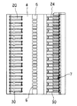
複数の第一の支持片20は、図3ないし図7に示すように、容器本体1を形成する各側壁4の内面上下方向に所定のピッチで並設され、容器本体1の正面寄りに位置して基板Wの側部周縁を樹脂層30を介し水平に支持する。各第一の支持片20は、各側壁4の内面から容器本体1の内方向に突出して基板Wの側部周縁を樹脂層30を介し水平に支持する薄肉領域21と、この薄肉領域21の外側(側壁4側)に形成されて基板Wの飛び出しや移動を規制する厚肉領域22とを備えた平面略半円形に形成され、これら薄肉領域21と厚肉領域22との間には、基板Wの厚さ相当の段差23が平面視で円弧状に形成される。
As shown in FIGS. 3 to 7, the plurality of
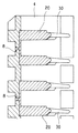
複数の第二の支持片24は、図3ないし図5、図8、図9に示すように、容器本体1を形成する各側壁4の内面上下方向に所定のピッチで並設され、容器本体1の背面壁寄りに位置して基板Wの側部周縁を樹脂層30を介し水平に支持する。各第二の支持片24は、各側壁4の内面から容器本体1の内方向に突出して基板Wの側部周縁を樹脂層30を介し水平に支持する薄肉領域21Aを略フラットに備え、平面略台形に形成される。
As shown in FIGS. 3 to 5, 8, and 9, the plurality of
樹脂層30は、容器本体1の材料よりも低摩擦性・低磨耗性の樹脂、具体的にはポリブチレンテレフタレート(PBT)やポリエーテルエーテルケトン(PEEK)を用いた二色成形法により形成される。この樹脂層30は、ASTM D1894に従って鋼に対する摩擦係数を測定した場合の測定値が0.33未満、好ましくは0.20以下とされる。
The
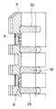
このような樹脂層30は、滑りの悪い基板Wと接触する各側壁4の接触部5、第一の支持片20の表裏面、及び第二の支持片24の表裏面を被覆するよう機能する。基板Wと接触する各側壁4の接触部5としては、図3等に示すように、一対の側壁4における第一、第二の支持片20・24に基板Wが支持された場合に、基板Wを通る中心線CLのうち、基板Wの出し入れ方向と直交する交差線の延長線EL上に位置する複数の内面部分6、及び各側壁4の屈曲した後部内面7があげられる。
Such a
上記において、容器本体1を製造する場合には、先ず、側壁4用の金型にポリカーボネート等の材料を充填して各側壁4と複数の第一、第二の支持片20・24を一体成形するとともに、金型に低摩擦性・低磨耗性の樹脂を充填して基板Wの周縁部と接触する各側壁4の接触部5、及び第一、第二の支持片20・24を樹脂層30で被覆・一体化する。
In the above, when the
この際、低摩擦性・低磨耗性の樹脂は各側壁4の外面側から充填されるが、各側壁4のゲートの外面側に、被覆部分が抜けないよう、内面側よりも寸法の大きいフランジ8が予め形成されるのが好ましい。これは、寸法の大きいフランジ8を予め形成しておけば、側壁4の樹脂と樹脂層30の樹脂との界面の接着力が小さく、十分な接着強度が期待できない場合でも、被覆層が剥離したり、位置ずれするのを抑制防止することができるからである。
At this time, the low-friction and low-abrasion resin is filled from the outer surface side of each
こうして各側壁4の接触部5、及び第一、第二の支持片20・24を樹脂層30で被覆したら、一対の側壁4を容器本体1用の成形金型にインサートし、その後、成形金型にポリカーボネート等の樹脂を射出し、冷却硬化させれば、両側側壁4を一体に備えた容器本体1を製造することができる。
When the
上記構成によれば、容器本体1の基板Wと接触する大部分を容器本体1とは別体の樹脂層30で覆い、滑り性を向上させるので、例え基板収納容器が衝撃を受けても、基板Wの周縁部や裏面と第一、第二の支持片20・24とが擦れて基板Wが損傷したり、パーティクルが発生して基板Wの表面に付着し、製品の機能や歩留まりの低下を招くのを著しく抑制防止することができる。
According to the above configuration, most of the
また、基板Wの周縁部から半径内方向に3mmの排他領域を狭くして歩留まりを向上させることができる。また、従来の平面略く字形の支持片を、第一、第二の支持片20・24に分割して個別に突出させ、この第一、第二の支持片20・24の間にクリアランス25を形成するので、基板Wとの接触面積を減少させ、有機物による汚染を大幅に低減することができる。
Further, the yield can be improved by narrowing the exclusive region of 3 mm in the radial inward direction from the peripheral edge of the substrate W. Further, the conventional planar substantially square-shaped support piece is divided into first and
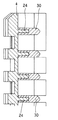
次に、図10は本発明の第2の実施形態を示すもので、この場合には、容器本体1の奥の壁である背面壁の内面に、基板Wの後部周縁を支持する左右一対の弾性のリヤリテーナ9を装着し、第一、第二の支持片20・24を個別に形成するのではなく、連続的に一体形成し、これら第一、第二の支持片20・24の平面半円弧形を呈した中間部分を第一、第二の支持片20・24よりも薄肉に形成して基板Wの裏面周縁部と非接触とするようにしている。
Next, FIG. 10 shows a second embodiment of the present invention. In this case, a pair of left and right supporting the rear periphery of the substrate W is supported on the inner surface of the back wall, which is the back wall of the
一対の弾性のリヤリテーナ9を上下方向に複数並設される。各リヤリテーナ9は、弾力性、耐磨耗性、低摩擦性に優れ、基板Wに対する汚染のおそれの少ない材料、例えばポリブチレンテレフタレート、ポリエーテルエーテルケトン、ポリエステル系エラストマー、ポリオレフィン系エラストマー等を用いて断面略U字形やV字形に成形される。 A plurality of pairs of elastic rear retainers 9 are arranged in the vertical direction. Each rear retainer 9 is made of a material excellent in elasticity, wear resistance, low friction, and less likely to contaminate the substrate W, such as polybutylene terephthalate, polyetheretherketone, polyester elastomer, polyolefin elastomer, etc. It is molded into a substantially U-shaped or V-shaped cross section.
各第一の支持片20は、各側壁4の内面から容器本体1の内方向に突出して基板Wの側部周縁を樹脂層30を介し水平に支持する薄肉領域21と、この薄肉領域21の外側に形成されて基板Wの飛び出しや移動を規制する厚肉領域22とを備え、これら薄肉領域21と厚肉領域22との間には、基板Wの厚さ相当の段差23が形成される。その他の部分については、上記実施形態と同様であるので説明を省略する。
Each
本実施形態においても上記実施形態と略同様の作用効果が期待でき、しかも、各基板Wを緩衝機能を有するフロントリテーナ13とリヤリテーナ9とで前後方向から挟んで保護するので、例え輸送時に基板収納容器が衝撃を受けても、基板Wのがたつくことがなく、基板Wを安全に保持することができるのは明らかである。
In this embodiment, substantially the same effect as that of the above embodiment can be expected, and each substrate W is protected by being sandwiched between the
なお、上記実施形態では容器本体1と蓋体10に、蓋体10固定用の係止機構を配設したが、何らこれに限定されるものではない。例えば、外部からの操作により、容器本体1を嵌合閉鎖する蓋体10を施錠・解錠する施錠機構を蓋体10に設置しても良い。また、基板Wと接触する各側壁4の接触部5は、一対の側壁4における第一、第二の支持片20・24に基板Wが支持された場合に、基板Wを通る中心線CLのうち、基板Wの出し入れ方向と直交する交差線の延長線EL上に位置する内面部分6、及び各側壁4の屈曲した複数の後部内面7以外の部分でも良い。
In the above embodiment, the
また、各側壁4の屈曲した後部内面7と第二の支持片24とは、連続した樹脂層30に被覆されても良いし、そうでなくても良い。また、第一の支持片20を覆う樹脂層30に、薄肉領域21、厚肉領域22、及び段差23を形成しても良い。さらに、第一、第二の支持片20・24を備えた側壁4を容器本体1用の成形金型にインサートして一体成形しても良いが、レーザ溶接、熱溶着、超音波溶着により側壁4と容器本体1とを一体形成することもできる。
Further, the bent rear
この場合、各側壁4と容器本体1の残部との間にパッキン等のシール部材を介在させて一体化しても良く、このとき、シール部材を側壁4や容器本体1の残部に予め一体化しても良く、別部材とすることも可能である。
In this case, a seal member such as packing may be interposed between each
1 容器本体
2 リム部(開口部)
4 側壁
5 接触部
6 内面部分
7 後部内面
9 リヤリテーナ(リテーナ)
10 蓋体
13 フロントリテーナ
20 第一の支持片
21 薄肉領域
21A 薄肉領域
22 厚肉領域
23 段差
24 第二の支持片
25 クリアランス(空隙)
30 樹脂層
CL 中心線
EL 延長線
W 基板
1
4
DESCRIPTION OF
30 Resin layer CL Center line EL Extension line W Substrate
Claims (6)
基板の周縁部と接触する各側壁の接触部、第一の支持片、及び第二の支持片のうち、少なくとも第一、第二の支持片を容器本体よりも低摩擦性の樹脂層で被覆したことを特徴とする基板収納容器。 A substrate storage container for storing a substrate in a container main body, the first support piece provided on each of a pair of side walls forming the container main body, positioned on the opening side of the container main body, and supporting the peripheral edge of the substrate; A second support piece that is provided on each of the pair of side walls forming the container body and is located on the back wall side of the container body and supports the peripheral edge of the substrate,
At least the first and second support pieces of the contact portions of the side walls, the first support pieces, and the second support pieces that are in contact with the peripheral edge of the substrate are covered with a resin layer having a lower friction than the container body. A substrate storage container characterized by that.
低摩擦性の樹脂層を、ポリブチレンテレフタレート又はポリエーテルエーテルケトンとした請求項1ないし4いずれかに記載の基板収納容器。 The container body is formed using polycarbonate, cycloolefin polymer, or polyetherimide,
The substrate storage container according to any one of claims 1 to 4, wherein the low-friction resin layer is polybutylene terephthalate or polyether ether ketone.
6. The method for manufacturing a substrate storage container according to claim 1, wherein first and second support pieces are respectively formed on the pair of side walls, and contact portions of the side walls contacting the peripheral edge portion of the substrate, And, at least the first and second support pieces of the first and second support pieces are covered with a low friction resin layer, and the pair of side walls are inserted into a molding die for the container main body. A method for manufacturing a substrate storage container, comprising molding.
Priority Applications (8)
| Application Number | Priority Date | Filing Date | Title |
|---|---|---|---|
| JP2005144137A JP4584023B2 (en) | 2005-05-17 | 2005-05-17 | Substrate storage container and manufacturing method thereof |
| TW095115647A TWI322478B (en) | 2005-05-17 | 2006-05-02 | Substrate storage container and method for manufacturing the same |
| DE602006004105T DE602006004105D1 (en) | 2005-05-17 | 2006-05-09 | A substrate storage container and a method for its production |
| EP06252440A EP1724825B1 (en) | 2005-05-17 | 2006-05-09 | Substrate storage container and method for manufacturing the same |
| SG200603143A SG127808A1 (en) | 2005-05-17 | 2006-05-10 | Substrate storage container and method for manufacturing the same |
| KR1020060044443A KR101222792B1 (en) | 2005-05-17 | 2006-05-17 | Substrate Storage Container and Manufacturing Method Thereof |
| US11/436,040 US20060283774A1 (en) | 2005-05-17 | 2006-05-17 | Substrate storage container and method for manufacturing the same |
| CN2006100805735A CN1865096B (en) | 2005-05-17 | 2006-05-17 | Substrate storage container and manufacturing method thereof |
Applications Claiming Priority (1)
| Application Number | Priority Date | Filing Date | Title |
|---|---|---|---|
| JP2005144137A JP4584023B2 (en) | 2005-05-17 | 2005-05-17 | Substrate storage container and manufacturing method thereof |
Publications (2)
| Publication Number | Publication Date |
|---|---|
| JP2006324327A true JP2006324327A (en) | 2006-11-30 |
| JP4584023B2 JP4584023B2 (en) | 2010-11-17 |
Family
ID=36763027
Family Applications (1)
| Application Number | Title | Priority Date | Filing Date |
|---|---|---|---|
| JP2005144137A Expired - Lifetime JP4584023B2 (en) | 2005-05-17 | 2005-05-17 | Substrate storage container and manufacturing method thereof |
Country Status (8)
| Country | Link |
|---|---|
| US (1) | US20060283774A1 (en) |
| EP (1) | EP1724825B1 (en) |
| JP (1) | JP4584023B2 (en) |
| KR (1) | KR101222792B1 (en) |
| CN (1) | CN1865096B (en) |
| DE (1) | DE602006004105D1 (en) |
| SG (1) | SG127808A1 (en) |
| TW (1) | TWI322478B (en) |
Cited By (23)
| Publication number | Priority date | Publication date | Assignee | Title |
|---|---|---|---|---|
| WO2008065892A1 (en) * | 2006-12-01 | 2008-06-05 | Shin-Etsu Handotai Co., Ltd. | Multicolor molded item, method of multicolor molding and substrate accommodation container |
| WO2009052434A3 (en) * | 2007-10-17 | 2009-09-11 | Asyst Technologies Inc. | Method and apparatus for wafer support |
| JP2009272472A (en) * | 2008-05-08 | 2009-11-19 | Shin Etsu Polymer Co Ltd | Substrate storage container |
| JP2010027861A (en) * | 2008-07-18 | 2010-02-04 | Shin Etsu Polymer Co Ltd | Substrate storage container |
| JP2011091225A (en) * | 2009-10-23 | 2011-05-06 | Shin Etsu Polymer Co Ltd | Substrate-housing container |
| CN102142387A (en) * | 2010-12-10 | 2011-08-03 | 北京七星华创电子股份有限公司 | Vertical crystal boat for semiconductor equipment for heat treatment |
| JP2011253960A (en) * | 2010-06-02 | 2011-12-15 | Shin Etsu Polymer Co Ltd | Substrate storage container |
| JP2012243919A (en) * | 2011-05-18 | 2012-12-10 | Shin Etsu Polymer Co Ltd | Wafer storage container |
| WO2013069088A1 (en) * | 2011-11-08 | 2013-05-16 | ミライアル株式会社 | Wafer storage container |
| JP5301731B2 (en) * | 2010-05-24 | 2013-09-25 | ミライアル株式会社 | Substrate storage container |
| WO2014080454A1 (en) * | 2012-11-20 | 2014-05-30 | ミライアル株式会社 | Wafer storage container |
| WO2014087486A1 (en) * | 2012-12-04 | 2014-06-12 | ミライアル株式会社 | Structure for fastening together resin members in substrate housing container |
| US8800774B2 (en) | 2005-07-08 | 2014-08-12 | Brooks Automation, Inc. | Workpiece support structures and apparatus for accessing same |
| JP2014192230A (en) * | 2013-03-26 | 2014-10-06 | Shin Etsu Polymer Co Ltd | Substrate storage container |
| KR20150030025A (en) * | 2013-09-11 | 2015-03-19 | 삼성전자주식회사 | Wafer loaders having buffer regions |
| WO2016047163A1 (en) * | 2014-09-26 | 2016-03-31 | ミライアル株式会社 | Substrate storing container |
| JP2017080930A (en) * | 2015-10-23 | 2017-05-18 | 三菱レイヨン株式会社 | Fiber-reinforced resin molded product and method for producing the same |
| KR20170136500A (en) | 2015-04-10 | 2017-12-11 | 신에츠 폴리머 가부시키가이샤 | Substrate storage container |
| JPWO2017006406A1 (en) * | 2015-07-03 | 2018-04-19 | ミライアル株式会社 | Substrate storage container |
| CN110021542A (en) * | 2018-01-08 | 2019-07-16 | 家登精密工业股份有限公司 | Container door supporting structure |
| JPWO2019030863A1 (en) * | 2017-08-09 | 2020-09-17 | ミライアル株式会社 | Board storage container |
| WO2022019081A1 (en) * | 2020-07-22 | 2022-01-27 | 信越ポリマー株式会社 | Storage container and method for manufacturing same |
| KR20220119155A (en) * | 2020-01-02 | 2022-08-26 | 엔테그리스, 아이엔씨. | Bulk container with steel overpack |
Families Citing this family (31)
| Publication number | Priority date | Publication date | Assignee | Title |
|---|---|---|---|---|
| US8528738B2 (en) * | 2006-06-13 | 2013-09-10 | Entegris, Inc. | Reusable resilient cushion for wafer container |
| TWI316040B (en) * | 2006-11-10 | 2009-10-21 | Innolux Display Corp | Packing box for glass substrate and a package structure of a glass substrate using the same |
| WO2008104006A2 (en) * | 2007-02-20 | 2008-08-28 | George Fechter Hoffman | Abrasion resistant panel |
| WO2008102804A1 (en) * | 2007-02-21 | 2008-08-28 | Shin-Etsu Polymer Co., Ltd. | Injection molding die and injection molding method |
| KR101525753B1 (en) * | 2008-01-13 | 2015-06-09 | 엔테그리스, 아이엔씨. | Methods and apparatuses for large diameter wafer handling |
| CN102017119B (en) * | 2008-03-13 | 2014-01-01 | 安格斯公司 | Wafer container with tubular environmental control components |
| TWI371076B (en) | 2008-08-27 | 2012-08-21 | Gudeng Prec Industral Co Ltd | A wafer container with at least one supporting module having a long slot |
| US8413815B2 (en) * | 2008-08-27 | 2013-04-09 | Gudeng Precision Industrial Co, Ltd | Wafer container with at least one purgeable supporting module having a long slot |
| US8387799B2 (en) | 2008-08-27 | 2013-03-05 | Gudeng Precision Industrial Co, Ltd. | Wafer container with purgeable supporting module |
| US8413814B2 (en) * | 2008-08-27 | 2013-04-09 | Gudeng Precision Industrial Co, Ltd | Front opening unified pod disposed with purgeable supporting module |
| CN102362340B (en) * | 2009-05-13 | 2013-12-25 | 未来儿株式会社 | Semiconductor wafer storage container |
| DE112010005511B4 (en) * | 2010-04-20 | 2016-06-02 | Miraial Co., Ltd. | Substrate storage container with movable support structures |
| US20110259840A1 (en) * | 2010-04-23 | 2011-10-27 | Advanced Semiconductor Engineering, Inc. | Semiconductor package magazine |
| TWM419217U (en) * | 2011-06-08 | 2011-12-21 | Chipbond Technology Corp | Electronic component carrier Cleaning rack |
| SG11201407231PA (en) | 2012-05-04 | 2014-12-30 | Entergris Inc | Replaceable wafer support backstop |
| WO2015037083A1 (en) * | 2013-09-11 | 2015-03-19 | ミライアル株式会社 | Substrate storage container |
| KR102220807B1 (en) * | 2013-09-24 | 2021-03-02 | 삼성전자주식회사 | Electrically Conductive Resin Composition and Display Apparatus Applying the Same |
| US9734930B2 (en) | 2013-09-24 | 2017-08-15 | Samsung Electronics Co., Ltd. | Conductive resin composition and display device using the same |
| TW201611169A (en) * | 2014-08-28 | 2016-03-16 | 安堤格里斯公司 | Substrate container |
| TWI617613B (en) * | 2015-09-08 | 2018-03-11 | 科騰聚合物美國有限責任公司 | Copolyester/controlled distribution styrenic block copolymer blends and methods of making and using same |
| US20170137589A1 (en) * | 2015-11-16 | 2017-05-18 | Samsung Electronics Co., Ltd. | Methods of modifying surfaces of structures used in the manufacture of a semiconductor device via fluorination |
| US11309200B2 (en) * | 2017-02-27 | 2022-04-19 | Miraial Co., Ltd. | Substrate storage container |
| US10811291B2 (en) * | 2017-11-08 | 2020-10-20 | Taiwan Semiconductor Manufacturing Company, Ltd. | Wafer container and method for holding wafer |
| JP6992240B2 (en) * | 2017-11-16 | 2022-01-13 | 信越ポリマー株式会社 | Board storage container |
| US11335576B2 (en) | 2018-10-29 | 2022-05-17 | Miraial Co., Ltd. | Method for molding substrate storing container, mold, and substrate storing container |
| US10978326B2 (en) | 2018-10-29 | 2021-04-13 | Taiwan Semiconductor Manufacturing Co, , Ltd. | Semiconductor wafer storage device |
| US11756816B2 (en) * | 2019-07-26 | 2023-09-12 | Applied Materials, Inc. | Carrier FOUP and a method of placing a carrier |
| KR102552458B1 (en) * | 2019-07-31 | 2023-07-06 | 가부시키가이샤 코쿠사이 엘렉트릭 | Substrate processing apparatus, substrate support, and method of manufacturing semiconductor device |
| TWI751814B (en) * | 2020-09-22 | 2022-01-01 | 家登精密工業股份有限公司 | Central support device for supporting sheets and storage equipment for storing sheets |
| JP2024533650A (en) * | 2021-09-22 | 2024-09-12 | インテグリス・インコーポレーテッド | Process Carrier |
| TWI855914B (en) * | 2023-05-04 | 2024-09-11 | 家登精密工業股份有限公司 | Protection device for substrate container |
Citations (7)
| Publication number | Priority date | Publication date | Assignee | Title |
|---|---|---|---|---|
| JPH0497346U (en) * | 1991-02-22 | 1992-08-24 | ||
| JP2000012673A (en) * | 1998-05-28 | 2000-01-14 | Fluoroware Inc | Wafer carrier and method of manufacturing the same |
| JP2002026116A (en) * | 2000-05-29 | 2002-01-25 | Middlesex Industries Sa | Container for transporting flat object to be transported |
| JP2002305239A (en) * | 2001-04-06 | 2002-10-18 | Shin Etsu Polymer Co Ltd | Wafer storage container and production method therefor |
| JP2003068839A (en) * | 2001-08-24 | 2003-03-07 | Shin Etsu Polymer Co Ltd | Substrate container and its manufacturing method |
| JP2005005525A (en) * | 2003-06-12 | 2005-01-06 | Shin Etsu Polymer Co Ltd | Substrate storage container |
| JP2005510868A (en) * | 2001-11-27 | 2005-04-21 | エンテグリス・インコーポレーテッド | Semiconductor element handling device with electrostatic dissipative film |
Family Cites Families (18)
| Publication number | Priority date | Publication date | Assignee | Title |
|---|---|---|---|---|
| JP2816864B2 (en) * | 1989-07-07 | 1998-10-27 | 大塚化学株式会社 | Transfer wafer basket and storage case |
| US5575394A (en) * | 1994-07-15 | 1996-11-19 | Fluoroware, Inc. | Wafer shipper and package |
| US5816410A (en) * | 1994-07-15 | 1998-10-06 | Fluoroware, Inc. | Wafer cushions for wafer shipper |
| JP3145252B2 (en) * | 1994-07-29 | 2001-03-12 | 淀川化成株式会社 | Substrate supporting side plate and cassette using the same |
| US5706946A (en) * | 1995-06-26 | 1998-01-13 | Kakizaki Manufacturing Co., Ltd | Thin-plate supporting container |
| US5788082A (en) * | 1996-07-12 | 1998-08-04 | Fluoroware, Inc. | Wafer carrier |
| US6039186A (en) * | 1997-04-16 | 2000-03-21 | Fluoroware, Inc. | Composite transport carrier |
| JPH1159779A (en) * | 1997-06-11 | 1999-03-02 | Kawasaki Steel Corp | Storage container |
| US6010008A (en) * | 1997-07-11 | 2000-01-04 | Fluoroware, Inc. | Transport module |
| JP4334123B2 (en) * | 2000-09-27 | 2009-09-30 | 信越ポリマー株式会社 | Precision substrate storage container |
| JP4596681B2 (en) * | 2001-05-23 | 2010-12-08 | 信越ポリマー株式会社 | Storage container and manufacturing method thereof |
| JP3938293B2 (en) * | 2001-05-30 | 2007-06-27 | 信越ポリマー株式会社 | Precision substrate storage container and its holding member |
| KR100615761B1 (en) * | 2002-09-11 | 2006-08-28 | 신에츠 폴리머 가부시키가이샤 | Substrate-storing container |
| JP2004250084A (en) * | 2003-02-21 | 2004-09-09 | Sharp Corp | Flexible substrate storage device and flexible substrate storage method |
| US20040226845A1 (en) * | 2003-05-14 | 2004-11-18 | Raj Babak R. | Method and apparatus for transporting articles |
| JP4573566B2 (en) * | 2004-04-20 | 2010-11-04 | 信越ポリマー株式会社 | Storage container |
| JP4667769B2 (en) * | 2004-06-11 | 2011-04-13 | 信越ポリマー株式会社 | Substrate storage container |
| JP2006269771A (en) * | 2005-03-24 | 2006-10-05 | Miraial Kk | Airtight container |
-
2005
- 2005-05-17 JP JP2005144137A patent/JP4584023B2/en not_active Expired - Lifetime
-
2006
- 2006-05-02 TW TW095115647A patent/TWI322478B/en not_active IP Right Cessation
- 2006-05-09 EP EP06252440A patent/EP1724825B1/en not_active Expired - Lifetime
- 2006-05-09 DE DE602006004105T patent/DE602006004105D1/en active Active
- 2006-05-10 SG SG200603143A patent/SG127808A1/en unknown
- 2006-05-17 CN CN2006100805735A patent/CN1865096B/en not_active Expired - Fee Related
- 2006-05-17 KR KR1020060044443A patent/KR101222792B1/en active Active
- 2006-05-17 US US11/436,040 patent/US20060283774A1/en not_active Abandoned
Patent Citations (7)
| Publication number | Priority date | Publication date | Assignee | Title |
|---|---|---|---|---|
| JPH0497346U (en) * | 1991-02-22 | 1992-08-24 | ||
| JP2000012673A (en) * | 1998-05-28 | 2000-01-14 | Fluoroware Inc | Wafer carrier and method of manufacturing the same |
| JP2002026116A (en) * | 2000-05-29 | 2002-01-25 | Middlesex Industries Sa | Container for transporting flat object to be transported |
| JP2002305239A (en) * | 2001-04-06 | 2002-10-18 | Shin Etsu Polymer Co Ltd | Wafer storage container and production method therefor |
| JP2003068839A (en) * | 2001-08-24 | 2003-03-07 | Shin Etsu Polymer Co Ltd | Substrate container and its manufacturing method |
| JP2005510868A (en) * | 2001-11-27 | 2005-04-21 | エンテグリス・インコーポレーテッド | Semiconductor element handling device with electrostatic dissipative film |
| JP2005005525A (en) * | 2003-06-12 | 2005-01-06 | Shin Etsu Polymer Co Ltd | Substrate storage container |
Cited By (44)
| Publication number | Priority date | Publication date | Assignee | Title |
|---|---|---|---|---|
| US8800774B2 (en) | 2005-07-08 | 2014-08-12 | Brooks Automation, Inc. | Workpiece support structures and apparatus for accessing same |
| JP2008140948A (en) * | 2006-12-01 | 2008-06-19 | Shin Etsu Handotai Co Ltd | Multicolor molded body, multicolor molding method, and substrate storage container |
| WO2008065892A1 (en) * | 2006-12-01 | 2008-06-05 | Shin-Etsu Handotai Co., Ltd. | Multicolor molded item, method of multicolor molding and substrate accommodation container |
| US8318275B2 (en) | 2006-12-01 | 2012-11-27 | Shin-Etsu Handotai Co., Ltd. | Multi-color molding article, multicolor molding method and substrate storage container |
| KR101410162B1 (en) * | 2006-12-01 | 2014-06-19 | 신에쯔 한도타이 가부시키가이샤 | Multicolor molding article,multicolor molding method and substrate storage container |
| TWI418456B (en) * | 2006-12-01 | 2013-12-11 | 信越半導體股份有限公司 | Substrate storage container |
| WO2009052434A3 (en) * | 2007-10-17 | 2009-09-11 | Asyst Technologies Inc. | Method and apparatus for wafer support |
| JP2009272472A (en) * | 2008-05-08 | 2009-11-19 | Shin Etsu Polymer Co Ltd | Substrate storage container |
| JP2010027861A (en) * | 2008-07-18 | 2010-02-04 | Shin Etsu Polymer Co Ltd | Substrate storage container |
| JP2011091225A (en) * | 2009-10-23 | 2011-05-06 | Shin Etsu Polymer Co Ltd | Substrate-housing container |
| JP5301731B2 (en) * | 2010-05-24 | 2013-09-25 | ミライアル株式会社 | Substrate storage container |
| JP2011253960A (en) * | 2010-06-02 | 2011-12-15 | Shin Etsu Polymer Co Ltd | Substrate storage container |
| CN102142387A (en) * | 2010-12-10 | 2011-08-03 | 北京七星华创电子股份有限公司 | Vertical crystal boat for semiconductor equipment for heat treatment |
| CN102142387B (en) * | 2010-12-10 | 2013-01-23 | 北京七星华创电子股份有限公司 | Vertical crystal boat for semiconductor equipment for heat treatment |
| JP2012243919A (en) * | 2011-05-18 | 2012-12-10 | Shin Etsu Polymer Co Ltd | Wafer storage container |
| WO2013069088A1 (en) * | 2011-11-08 | 2013-05-16 | ミライアル株式会社 | Wafer storage container |
| US8960442B2 (en) | 2011-11-08 | 2015-02-24 | Miraial Co., Ltd. | Wafer storing container |
| KR101738219B1 (en) | 2011-11-08 | 2017-05-19 | 미라이얼 가부시키가이샤 | Wafer storage container |
| WO2014080454A1 (en) * | 2012-11-20 | 2014-05-30 | ミライアル株式会社 | Wafer storage container |
| US9768045B2 (en) | 2012-11-20 | 2017-09-19 | Miraial Co., Ltd. | Substrate storing container |
| JPWO2014080454A1 (en) * | 2012-11-20 | 2017-01-05 | ミライアル株式会社 | Substrate storage container |
| WO2014087486A1 (en) * | 2012-12-04 | 2014-06-12 | ミライアル株式会社 | Structure for fastening together resin members in substrate housing container |
| US9748127B2 (en) | 2012-12-04 | 2017-08-29 | Miraial Co., Ltd. | Structure for fastening together resin members in substrate storing container |
| JP2014192230A (en) * | 2013-03-26 | 2014-10-06 | Shin Etsu Polymer Co Ltd | Substrate storage container |
| KR102143884B1 (en) * | 2013-09-11 | 2020-08-12 | 삼성전자주식회사 | Wafer loaders having buffer regions |
| KR20150030025A (en) * | 2013-09-11 | 2015-03-19 | 삼성전자주식회사 | Wafer loaders having buffer regions |
| US10535540B2 (en) | 2014-09-26 | 2020-01-14 | Miraial Co., Ltd. | Substrate storing container |
| JPWO2016047163A1 (en) * | 2014-09-26 | 2017-07-06 | ミライアル株式会社 | Substrate storage container |
| WO2016046985A1 (en) * | 2014-09-26 | 2016-03-31 | ミライアル株式会社 | Substrate storing container |
| WO2016047163A1 (en) * | 2014-09-26 | 2016-03-31 | ミライアル株式会社 | Substrate storing container |
| KR20170136500A (en) | 2015-04-10 | 2017-12-11 | 신에츠 폴리머 가부시키가이샤 | Substrate storage container |
| JPWO2017006406A1 (en) * | 2015-07-03 | 2018-04-19 | ミライアル株式会社 | Substrate storage container |
| JP2017080930A (en) * | 2015-10-23 | 2017-05-18 | 三菱レイヨン株式会社 | Fiber-reinforced resin molded product and method for producing the same |
| JPWO2019030863A1 (en) * | 2017-08-09 | 2020-09-17 | ミライアル株式会社 | Board storage container |
| CN110021542A (en) * | 2018-01-08 | 2019-07-16 | 家登精密工业股份有限公司 | Container door supporting structure |
| CN110021542B (en) * | 2018-01-08 | 2023-10-03 | 家登精密工业股份有限公司 | Container door panel supporting structure |
| KR20220119155A (en) * | 2020-01-02 | 2022-08-26 | 엔테그리스, 아이엔씨. | Bulk container with steel overpack |
| JP2023519069A (en) * | 2020-01-02 | 2023-05-10 | インテグリス・インコーポレーテッド | Bulk vessel with steel overpack |
| JP7479478B2 (en) | 2020-01-02 | 2024-05-08 | インテグリス・インコーポレーテッド | Bulk container with steel overpack |
| KR102768345B1 (en) * | 2020-01-02 | 2025-02-18 | 엔테그리스, 아이엔씨. | Bulk container with steel overpack |
| JP2022021616A (en) * | 2020-07-22 | 2022-02-03 | 信越ポリマー株式会社 | Storage container and method for manufacturing the same |
| WO2022019081A1 (en) * | 2020-07-22 | 2022-01-27 | 信越ポリマー株式会社 | Storage container and method for manufacturing same |
| JP7388712B2 (en) | 2020-07-22 | 2023-11-29 | 信越ポリマー株式会社 | Storage container manufacturing method |
| US12347710B2 (en) | 2020-07-22 | 2025-07-01 | Shin-Etsu Polymer Co., Ltd. | Storage container and manufacturing method of the same |
Also Published As
| Publication number | Publication date |
|---|---|
| KR20060119816A (en) | 2006-11-24 |
| DE602006004105D1 (en) | 2009-01-22 |
| EP1724825A1 (en) | 2006-11-22 |
| TWI322478B (en) | 2010-03-21 |
| TW200644150A (en) | 2006-12-16 |
| KR101222792B1 (en) | 2013-01-15 |
| EP1724825B1 (en) | 2008-12-10 |
| CN1865096B (en) | 2010-05-12 |
| US20060283774A1 (en) | 2006-12-21 |
| JP4584023B2 (en) | 2010-11-17 |
| SG127808A1 (en) | 2006-12-29 |
| CN1865096A (en) | 2006-11-22 |
Similar Documents
| Publication | Publication Date | Title |
|---|---|---|
| JP4584023B2 (en) | Substrate storage container and manufacturing method thereof | |
| JP4540529B2 (en) | Storage container | |
| JP5269077B2 (en) | Support and substrate storage container | |
| JP4213078B2 (en) | Retainer and substrate storage container | |
| JP5738118B2 (en) | Substrate storage container | |
| JP4338617B2 (en) | Substrate storage container | |
| WO2021234808A1 (en) | Substrate storage container | |
| CN101536174B (en) | Substrate container | |
| JP6050981B2 (en) | Mask blank storage case and mask blank storage body | |
| JP5363277B2 (en) | Substrate storage container and support member | |
| JP6412440B2 (en) | Substrate storage container | |
| JP4592449B2 (en) | Substrate storage container | |
| JP5409343B2 (en) | Substrate storage container | |
| JP2011086775A (en) | Substrate storage container and cover | |
| KR20200085328A (en) | Substrate storage container | |
| JP5449974B2 (en) | Precision substrate storage container | |
| JP2009177050A (en) | Storage container for processing jig | |
| JP4459015B2 (en) | Substrate storage container | |
| KR102125579B1 (en) | Mask blank storing case and mask blank package | |
| KR101486612B1 (en) | Container for processing tool for mounting substrate | |
| JP2008021743A (en) | Housing container for semiconductor wafer | |
| JP2009274743A (en) | Container and method for manufacturing it | |
| JP2006339340A (en) | Wafer container | |
| JP2008135434A (en) | Substrate storing container | |
| CN118255049A (en) | Substrate storage box and substrate storage body |
Legal Events
| Date | Code | Title | Description |
|---|---|---|---|
| A621 | Written request for application examination |
Free format text: JAPANESE INTERMEDIATE CODE: A621 Effective date: 20070815 |
|
| A977 | Report on retrieval |
Free format text: JAPANESE INTERMEDIATE CODE: A971007 Effective date: 20090928 |
|
| A131 | Notification of reasons for refusal |
Free format text: JAPANESE INTERMEDIATE CODE: A131 Effective date: 20091006 |
|
| A521 | Request for written amendment filed |
Free format text: JAPANESE INTERMEDIATE CODE: A523 Effective date: 20091120 |
|
| A02 | Decision of refusal |
Free format text: JAPANESE INTERMEDIATE CODE: A02 Effective date: 20100427 |
|
| A521 | Request for written amendment filed |
Free format text: JAPANESE INTERMEDIATE CODE: A523 Effective date: 20100705 |
|
| A521 | Request for written amendment filed |
Free format text: JAPANESE INTERMEDIATE CODE: A523 Effective date: 20100709 |
|
| A521 | Request for written amendment filed |
Free format text: JAPANESE INTERMEDIATE CODE: A523 Effective date: 20100714 |
|
| A911 | Transfer to examiner for re-examination before appeal (zenchi) |
Free format text: JAPANESE INTERMEDIATE CODE: A911 Effective date: 20100803 |
|
| TRDD | Decision of grant or rejection written | ||
| A01 | Written decision to grant a patent or to grant a registration (utility model) |
Free format text: JAPANESE INTERMEDIATE CODE: A01 Effective date: 20100831 |
|
| A01 | Written decision to grant a patent or to grant a registration (utility model) |
Free format text: JAPANESE INTERMEDIATE CODE: A01 |
|
| A61 | First payment of annual fees (during grant procedure) |
Free format text: JAPANESE INTERMEDIATE CODE: A61 Effective date: 20100901 |
|
| R150 | Certificate of patent or registration of utility model |
Free format text: JAPANESE INTERMEDIATE CODE: R150 Ref document number: 4584023 Country of ref document: JP Free format text: JAPANESE INTERMEDIATE CODE: R150 |
|
| FPAY | Renewal fee payment (event date is renewal date of database) |
Free format text: PAYMENT UNTIL: 20130910 Year of fee payment: 3 |
|
| S531 | Written request for registration of change of domicile |
Free format text: JAPANESE INTERMEDIATE CODE: R313531 |
|
| FPAY | Renewal fee payment (event date is renewal date of database) |
Free format text: PAYMENT UNTIL: 20130910 Year of fee payment: 3 |
|
| R350 | Written notification of registration of transfer |
Free format text: JAPANESE INTERMEDIATE CODE: R350 |
|
| R250 | Receipt of annual fees |
Free format text: JAPANESE INTERMEDIATE CODE: R250 |
|
| R250 | Receipt of annual fees |
Free format text: JAPANESE INTERMEDIATE CODE: R250 |
|
| R250 | Receipt of annual fees |
Free format text: JAPANESE INTERMEDIATE CODE: R250 |
|
| R250 | Receipt of annual fees |
Free format text: JAPANESE INTERMEDIATE CODE: R250 |
|
| S531 | Written request for registration of change of domicile |
Free format text: JAPANESE INTERMEDIATE CODE: R313531 |
|
| R350 | Written notification of registration of transfer |
Free format text: JAPANESE INTERMEDIATE CODE: R350 |
|
| EXPY | Cancellation because of completion of term |