JP2005296470A - ユニットバスの配管構造 - Google Patents
ユニットバスの配管構造 Download PDFInfo
- Publication number
- JP2005296470A JP2005296470A JP2004119562A JP2004119562A JP2005296470A JP 2005296470 A JP2005296470 A JP 2005296470A JP 2004119562 A JP2004119562 A JP 2004119562A JP 2004119562 A JP2004119562 A JP 2004119562A JP 2005296470 A JP2005296470 A JP 2005296470A
- Authority
- JP
- Japan
- Prior art keywords
- bathtub
- waterproof pan
- pipe
- faucet
- coupling member
- Prior art date
- Legal status (The legal status is an assumption and is not a legal conclusion. Google has not performed a legal analysis and makes no representation as to the accuracy of the status listed.)
- Granted
Links
- XLYOFNOQVPJJNP-UHFFFAOYSA-N water Substances O XLYOFNOQVPJJNP-UHFFFAOYSA-N 0.000 claims description 81
- 230000008878 coupling Effects 0.000 claims description 75
- 238000010168 coupling process Methods 0.000 claims description 75
- 238000005859 coupling reaction Methods 0.000 claims description 75
- 238000005406 washing Methods 0.000 claims description 66
- 238000004891 communication Methods 0.000 claims description 14
- 238000012423 maintenance Methods 0.000 abstract description 5
- 230000006872 improvement Effects 0.000 abstract description 3
- 230000000630 rising effect Effects 0.000 description 14
- 238000012856 packing Methods 0.000 description 11
- 238000010276 construction Methods 0.000 description 9
- 239000000463 material Substances 0.000 description 9
- 238000004078 waterproofing Methods 0.000 description 7
- 238000005192 partition Methods 0.000 description 6
- 239000000758 substrate Substances 0.000 description 5
- 238000003825 pressing Methods 0.000 description 4
- 229920002430 Fibre-reinforced plastic Polymers 0.000 description 3
- 230000008901 benefit Effects 0.000 description 3
- 235000008429 bread Nutrition 0.000 description 3
- 238000013461 design Methods 0.000 description 3
- 239000011151 fibre-reinforced plastic Substances 0.000 description 3
- 238000007689 inspection Methods 0.000 description 3
- 238000005452 bending Methods 0.000 description 2
- 230000000694 effects Effects 0.000 description 2
- 238000004519 manufacturing process Methods 0.000 description 2
- 239000002184 metal Substances 0.000 description 2
- 230000007480 spreading Effects 0.000 description 2
- 238000003892 spreading Methods 0.000 description 2
- 101150006573 PAN1 gene Proteins 0.000 description 1
- 229910000831 Steel Inorganic materials 0.000 description 1
- 230000008859 change Effects 0.000 description 1
- 238000004140 cleaning Methods 0.000 description 1
- 230000006866 deterioration Effects 0.000 description 1
- 230000007246 mechanism Effects 0.000 description 1
- 238000000034 method Methods 0.000 description 1
- 230000000149 penetrating effect Effects 0.000 description 1
- 230000008569 process Effects 0.000 description 1
- 239000010959 steel Substances 0.000 description 1
Images


Landscapes
- Sink And Installation For Waste Water (AREA)
- Bathtubs, Showers, And Their Attachments (AREA)
- Domestic Plumbing Installations (AREA)
Abstract
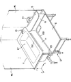
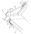
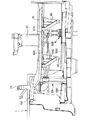
【解決手段】ユニットバス1は、浴槽11と、浴槽11の一側面に隣接して配置される洗い場用防水パン12と、浴槽のリム部11A1と当該防水パンの土手部12B1とを夫々、着脱自在に結合する1対の結合部材13A,13B、浴槽の一側面側にて結合部材、浴槽のリム部、及び防水パンの土手部により形成される開口部OPを着脱自在に且つ水密に閉塞するバスエプロン14と、防水パンの床面の配管取出し部19を介して外部から取り出され且つ浴槽用水栓25に接続される配管62A,62B,64A,64Bとを備える。一方の結合部材13Aに、連通孔43を形成し、この連通孔を介して配管を防水パンの側から浴槽の側に配管を通して浴槽用水栓に接続する。
【選択図】 図2
Description
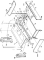
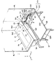
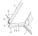
図3及び図4に示すように、浴槽11は、利用者が身体を伸ばして入浴できるように細長い内容積のバスタブTBを有し、そのバスタブTBの周囲にリム部11Aを形成している。リム部11Aは、その長手方向(Z軸方向)に沿って位置し且つ防水パン12に隣接する第1のリム部11A1と、この第1のリム部11A1に連なってバスタブTBの縁を一周する第2〜第4のリム部11A2〜11A4とから成る。
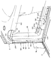
一方、防水パン12は、高さ方向(Y軸方向)において、浴槽11のリム部11Aよりも低い位置に設置される。防水パン12は、床面部12Aと、その床面部12Aの周囲に立ち上がりを一体に形成する土手部12Bから成る。床面部12Aは、洗い場の中心となる床面本体12A1と、長手方向(Z軸方向)の一端部に床面本体12A1から段差によって画成された略矩形状の段差部12A2とから成る。床面本体12A1は浴槽寄りの1つの角部に向かって緩やかに傾斜しており、その角部に形成された排水口31に導水できるようになっている。段差部12A2には、後述する給水配管部17が設置される。
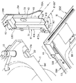
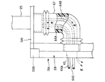
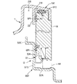
さらに、1対の結合部材13A,13Bのうち、第1の結合部材13Aの全体斜視図を図5に示す。この第1の結合部材13Aは、図5に示すように、浴室の壁体の一部を支持するための支持体(ポスト部)39と、略板状で所定厚さ及び所定長さを有する支柱体(ピラー部)41と、この支柱体41と支柱体39とを相互に剛結する矩形板状の中間部材40とを備える。この中間部材40は、その取り付け状態における下端側の一部が支柱体39より短く形成される一方で、その上端部は支柱体39と同一高さに形成されている。
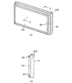
バスエプロン14は、所定厚さを有するFRPなどの素材で形成された所定厚さで略矩形状の板体である。このバスエプロン14の厚さは、第1及び第2の結合部材13A,13Bの膨張部41B,51Bの高さに略一致させている。
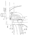
給水配管部17は、図3に示すように、防水パン12のZ軸方向の一端部に一体形成された段差部12A2の位置に設けられる。つまり、この給水配管部17は、防水パン12の床面の一部を成す段差部12A2の所定位置に立設された外部の配管(給水配管及び給湯配管)に接続する接続部61と、この接続部61に接続された2本の浴室配管62A,62B(給水用及び給湯用)と、この浴室配管62A,62Bに接続された洗い場水栓63と、及び浴室配管62A,62Bからそれぞれ分岐した分岐配管64A,64Bを備える。
ここで、上述したユニットバス1を現場で組み付けるための作業者による作業工程を説明する。なお、全てのコンポーネントは別体として一般家庭の戸建住宅や集合住宅などの現場に搬入されるものとする。
本実施形態に係るユニットバス1は以上のように構成されて機能することから、様々な利点を享受することができる。
11 浴槽
11A1 浴槽の一面側のリム部
12 洗い場用防水パン
12B1 洗い場用防水パンの一面側の土手部
13A、13B 第1及び第2の結合部材
14 バスエプロン
15 洗い場カウンタ
16 化粧板
17 給水配管部
19 配管接続部
25 浴槽水栓
43 連通孔
62A,62B、64A,64B 配管
63 洗い場水栓
65、66 カウンタ支持体
67 水受け材としてのチューブ
Claims (6)
- 上端縁にリム部が形成され且つ当該リム部の一部に浴槽用水栓が設置された浴槽と、
この浴槽の所定の一側面に隣接して配置され且つ土手部が形成された洗い場用防水パンと、
前記浴槽の前記一側面の前記防水パンに沿った方向の両端部にて当該浴槽のリム部と当該防水パンの土手部とをそれぞれ着脱自在に結合する1対の結合部材と、
前記浴槽の前記一側面側にて前記1対の結合部材、前記浴槽のリム部、及び前記防水パンの土手部により画成される開口部を着脱自在に且つ水密に閉塞するバスエプロンと、
前記洗い場用防水パンの床面の配管取出し部に接続され且つ少なくとも前記浴槽用水栓に接続される配管と、を備えたユニットバスであって、
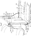
前記一方の結合部材に、前記浴槽の側と前記防水パンの側とを相互に連通させる連通孔を形成し、
当該一方の結合部材に形成された前記連通孔を介して前記配管を前記洗い場用防水パンの側から前記浴槽の側に通して前記浴槽用水栓に接続するように構成したことを特徴とするユニットバスの配管構造。 - 前記一方の結合部材の前記浴槽の側に、前記水栓に接続された前記配管からの漏水を前記防水パンの側に回収する水受け手段を設けたことを特徴とする請求項2に記載のユニットバスの配管構造。
- 前記水受け手段は、前記配管の前記水栓から前記一方の結合部材に至る配管部分の少なくとも一部を被う筒体であって、この筒体の前記一方の結合部材の側の端部を当該結合部材に前記連通孔を囲むように水密に接続したことを特徴とする請求項2に記載のユニットバスの配管構造。
- 前記配管は、前記浴槽用水栓に接続される給水配管と給湯配管の2本の配管から成ることを特徴とする請求項1乃至3の何れか一項に記載のユニットバスの配管構造。
- 前記配管は、その途中で分岐して洗い場用水栓にも接続されることを特徴とする請求項1乃至4の何れか一項に記載のユニットバスの配管構造。
- 前記配管取出し部から前記洗い場用水栓に至る前記配管の一部及び前記一方の結合部材を含むスペースの上方を被う洗い場用カウンタと、当該カウンタと前記防水パンの床面との間に在って前記スペースの側方を被う化粧板とを設けたことを特徴とする請求項1乃至5の何れか一項に記載のユニットバスの配管構造。
Priority Applications (1)
| Application Number | Priority Date | Filing Date | Title |
|---|---|---|---|
| JP2004119562A JP4501514B2 (ja) | 2004-04-14 | 2004-04-14 | ユニットバスの配管構造 |
Applications Claiming Priority (1)
| Application Number | Priority Date | Filing Date | Title |
|---|---|---|---|
| JP2004119562A JP4501514B2 (ja) | 2004-04-14 | 2004-04-14 | ユニットバスの配管構造 |
Publications (2)
| Publication Number | Publication Date |
|---|---|
| JP2005296470A true JP2005296470A (ja) | 2005-10-27 |
| JP4501514B2 JP4501514B2 (ja) | 2010-07-14 |
Family
ID=35328723
Family Applications (1)
| Application Number | Title | Priority Date | Filing Date |
|---|---|---|---|
| JP2004119562A Expired - Fee Related JP4501514B2 (ja) | 2004-04-14 | 2004-04-14 | ユニットバスの配管構造 |
Country Status (1)
| Country | Link |
|---|---|
| JP (1) | JP4501514B2 (ja) |
Cited By (9)
| Publication number | Priority date | Publication date | Assignee | Title |
|---|---|---|---|---|
| JP2007120869A (ja) * | 2005-10-28 | 2007-05-17 | Gastar Corp | 給湯システム |
| JP2007185317A (ja) * | 2006-01-12 | 2007-07-26 | Inax Corp | エプロンの固定構造 |
| JP2009172311A (ja) * | 2008-01-28 | 2009-08-06 | Panasonic Electric Works Bath & Life Co Ltd | 浴室ユニットの排水構造 |
| JP2010035805A (ja) * | 2008-08-05 | 2010-02-18 | Housetec Inc | 浴室ユニット |
| JP2010075233A (ja) * | 2008-09-24 | 2010-04-08 | Noritz Corp | バス水栓の配管構造 |
| JP2010227501A (ja) * | 2009-03-30 | 2010-10-14 | Toto Ltd | 浴室ユニット |
| JP2011206414A (ja) * | 2010-03-30 | 2011-10-20 | Rb Corp | 水密機能付き浴槽エプロン |
| JP2014133066A (ja) * | 2013-01-14 | 2014-07-24 | Lixil Corp | 浴室用カウンター |
| KR20170009544A (ko) | 2015-07-17 | 2017-01-25 | 주식회사 조이포라이프 | 욕조 시공용 프레임 장치 |
Citations (3)
| Publication number | Priority date | Publication date | Assignee | Title |
|---|---|---|---|---|
| JPS6457162U (ja) * | 1987-09-30 | 1989-04-10 | ||
| JPH10234603A (ja) * | 1997-02-27 | 1998-09-08 | Matsushita Electric Works Ltd | 浴槽の支持構造 |
| JP2003111687A (ja) * | 2001-10-05 | 2003-04-15 | Air Water Inc | 洗い場付きユニットバス |
-
2004
- 2004-04-14 JP JP2004119562A patent/JP4501514B2/ja not_active Expired - Fee Related
Patent Citations (3)
| Publication number | Priority date | Publication date | Assignee | Title |
|---|---|---|---|---|
| JPS6457162U (ja) * | 1987-09-30 | 1989-04-10 | ||
| JPH10234603A (ja) * | 1997-02-27 | 1998-09-08 | Matsushita Electric Works Ltd | 浴槽の支持構造 |
| JP2003111687A (ja) * | 2001-10-05 | 2003-04-15 | Air Water Inc | 洗い場付きユニットバス |
Cited By (9)
| Publication number | Priority date | Publication date | Assignee | Title |
|---|---|---|---|---|
| JP2007120869A (ja) * | 2005-10-28 | 2007-05-17 | Gastar Corp | 給湯システム |
| JP2007185317A (ja) * | 2006-01-12 | 2007-07-26 | Inax Corp | エプロンの固定構造 |
| JP2009172311A (ja) * | 2008-01-28 | 2009-08-06 | Panasonic Electric Works Bath & Life Co Ltd | 浴室ユニットの排水構造 |
| JP2010035805A (ja) * | 2008-08-05 | 2010-02-18 | Housetec Inc | 浴室ユニット |
| JP2010075233A (ja) * | 2008-09-24 | 2010-04-08 | Noritz Corp | バス水栓の配管構造 |
| JP2010227501A (ja) * | 2009-03-30 | 2010-10-14 | Toto Ltd | 浴室ユニット |
| JP2011206414A (ja) * | 2010-03-30 | 2011-10-20 | Rb Corp | 水密機能付き浴槽エプロン |
| JP2014133066A (ja) * | 2013-01-14 | 2014-07-24 | Lixil Corp | 浴室用カウンター |
| KR20170009544A (ko) | 2015-07-17 | 2017-01-25 | 주식회사 조이포라이프 | 욕조 시공용 프레임 장치 |
Also Published As
| Publication number | Publication date |
|---|---|
| JP4501514B2 (ja) | 2010-07-14 |
Similar Documents
| Publication | Publication Date | Title |
|---|---|---|
| JP4501514B2 (ja) | ユニットバスの配管構造 | |
| JP4345557B2 (ja) | ユニットバス | |
| JP2007010251A (ja) | ユニットバスの追焚配管構造 | |
| JP4345556B2 (ja) | ユニットバス | |
| JPH1129967A (ja) | 浴室用防水床パン | |
| JP5930880B2 (ja) | 浴室床 | |
| JP2009006169A (ja) | ユニットバス | |
| JP2006177093A (ja) | 浴室ユニット | |
| JP2005098089A (ja) | ヘッダーユニット | |
| JP4278459B2 (ja) | 洗い場付浴槽の配管固定構造 | |
| JPH057327Y2 (ja) | ||
| JP4429637B2 (ja) | 洗い場付浴槽の配管構造 | |
| CN115279982B (zh) | 卫生单元构造体及其施工方法 | |
| JP3338787B2 (ja) | 洗面室ユニットの床面構造 | |
| JP4813166B2 (ja) | 浴室ユニット | |
| JP3828373B2 (ja) | バスユニットの設置方法 | |
| JP2009189452A (ja) | 浴室ユニット | |
| JP5149094B2 (ja) | ユニットルームの壁構造 | |
| JPH09177145A (ja) | 住宅の配管設備 | |
| JPH0693631A (ja) | ユニットバスルーム | |
| JPH09268621A (ja) | 浴室用防水パン | |
| JP5344368B2 (ja) | 排水構造 | |
| JP6389051B2 (ja) | 浴室ユニット及びその施工方法 | |
| JP5601655B2 (ja) | 浴室建具及び浴室建具付きユニットバス | |
| JPH07229181A (ja) | 床下配管構造 |
Legal Events
| Date | Code | Title | Description |
|---|---|---|---|
| A621 | Written request for application examination |
Free format text: JAPANESE INTERMEDIATE CODE: A621 Effective date: 20061130 |
|
| A977 | Report on retrieval |
Free format text: JAPANESE INTERMEDIATE CODE: A971007 Effective date: 20080731 |
|
| A131 | Notification of reasons for refusal |
Free format text: JAPANESE INTERMEDIATE CODE: A131 Effective date: 20100105 |
|
| A521 | Written amendment |
Free format text: JAPANESE INTERMEDIATE CODE: A523 Effective date: 20100304 |
|
| TRDD | Decision of grant or rejection written | ||
| A01 | Written decision to grant a patent or to grant a registration (utility model) |
Free format text: JAPANESE INTERMEDIATE CODE: A01 Effective date: 20100330 |
|
| A01 | Written decision to grant a patent or to grant a registration (utility model) |
Free format text: JAPANESE INTERMEDIATE CODE: A01 |
|
| A61 | First payment of annual fees (during grant procedure) |
Free format text: JAPANESE INTERMEDIATE CODE: A61 Effective date: 20100412 |
|
| R150 | Certificate of patent or registration of utility model |
Ref document number: 4501514 Country of ref document: JP Free format text: JAPANESE INTERMEDIATE CODE: R150 Free format text: JAPANESE INTERMEDIATE CODE: R150 |
|
| FPAY | Renewal fee payment (event date is renewal date of database) |
Free format text: PAYMENT UNTIL: 20130430 Year of fee payment: 3 |
|
| FPAY | Renewal fee payment (event date is renewal date of database) |
Free format text: PAYMENT UNTIL: 20130430 Year of fee payment: 3 |
|
| FPAY | Renewal fee payment (event date is renewal date of database) |
Free format text: PAYMENT UNTIL: 20140430 Year of fee payment: 4 |
|
| LAPS | Cancellation because of no payment of annual fees |