JP2005294558A - Rare earth magnet and manufacturing method thereof - Google Patents
Rare earth magnet and manufacturing method thereof Download PDFInfo
- Publication number
- JP2005294558A JP2005294558A JP2004107998A JP2004107998A JP2005294558A JP 2005294558 A JP2005294558 A JP 2005294558A JP 2004107998 A JP2004107998 A JP 2004107998A JP 2004107998 A JP2004107998 A JP 2004107998A JP 2005294558 A JP2005294558 A JP 2005294558A
- Authority
- JP
- Japan
- Prior art keywords
- rare earth
- magnet
- resistant surface
- weather
- surface coating
- Prior art date
- Legal status (The legal status is an assumption and is not a legal conclusion. Google has not performed a legal analysis and makes no representation as to the accuracy of the status listed.)
- Granted
Links
- 229910052761 rare earth metal Inorganic materials 0.000 title claims abstract description 116
- 150000002910 rare earth metals Chemical class 0.000 title claims abstract description 75
- 238000004519 manufacturing process Methods 0.000 title claims abstract description 28
- 238000000576 coating method Methods 0.000 claims abstract description 88
- 239000011248 coating agent Substances 0.000 claims abstract description 87
- 238000010438 heat treatment Methods 0.000 claims abstract description 45
- 238000002844 melting Methods 0.000 claims abstract description 14
- 230000008018 melting Effects 0.000 claims abstract description 14
- 229910001172 neodymium magnet Inorganic materials 0.000 claims abstract description 8
- 229910000838 Al alloy Inorganic materials 0.000 claims abstract description 7
- 229910052710 silicon Inorganic materials 0.000 claims abstract description 7
- 229910052737 gold Inorganic materials 0.000 claims abstract description 6
- 229910052759 nickel Inorganic materials 0.000 claims abstract description 6
- 229910052697 platinum Inorganic materials 0.000 claims abstract description 6
- 238000011084 recovery Methods 0.000 claims description 68
- 229910045601 alloy Inorganic materials 0.000 claims description 28
- 239000000956 alloy Substances 0.000 claims description 28
- 230000032683 aging Effects 0.000 claims description 26
- 239000002994 raw material Substances 0.000 claims description 22
- 239000000203 mixture Substances 0.000 claims description 19
- 229910052777 Praseodymium Inorganic materials 0.000 claims description 15
- 238000005229 chemical vapour deposition Methods 0.000 claims description 15
- 238000005245 sintering Methods 0.000 claims description 15
- 229910052692 Dysprosium Inorganic materials 0.000 claims description 13
- 229910052779 Neodymium Inorganic materials 0.000 claims description 12
- 238000007598 dipping method Methods 0.000 claims description 11
- 229910052771 Terbium Inorganic materials 0.000 claims description 10
- 229910052796 boron Inorganic materials 0.000 claims description 10
- 239000000843 powder Substances 0.000 claims description 9
- ZOXJGFHDIHLPTG-UHFFFAOYSA-N Boron Chemical compound [B] ZOXJGFHDIHLPTG-UHFFFAOYSA-N 0.000 claims description 6
- 238000005240 physical vapour deposition Methods 0.000 claims description 6
- 229910052723 transition metal Inorganic materials 0.000 claims description 4
- 239000007791 liquid phase Substances 0.000 claims description 2
- 238000012545 processing Methods 0.000 abstract description 12
- 230000005291 magnetic effect Effects 0.000 description 55
- 238000000034 method Methods 0.000 description 52
- 230000008569 process Effects 0.000 description 24
- 239000007789 gas Substances 0.000 description 18
- XEEYBQQBJWHFJM-UHFFFAOYSA-N iron Substances [Fe] XEEYBQQBJWHFJM-UHFFFAOYSA-N 0.000 description 18
- 238000003754 machining Methods 0.000 description 16
- 238000010298 pulverizing process Methods 0.000 description 16
- 230000000694 effects Effects 0.000 description 15
- 229910052751 metal Inorganic materials 0.000 description 15
- 239000002184 metal Substances 0.000 description 15
- 238000000227 grinding Methods 0.000 description 10
- 239000000463 material Substances 0.000 description 10
- 230000015572 biosynthetic process Effects 0.000 description 9
- 230000007797 corrosion Effects 0.000 description 8
- 238000005260 corrosion Methods 0.000 description 8
- -1 ferroboron Substances 0.000 description 7
- 230000004907 flux Effects 0.000 description 7
- 239000012298 atmosphere Substances 0.000 description 6
- 239000002245 particle Substances 0.000 description 6
- 238000009826 distribution Methods 0.000 description 5
- 239000011261 inert gas Substances 0.000 description 5
- 230000004048 modification Effects 0.000 description 5
- 238000012986 modification Methods 0.000 description 5
- WYURNTSHIVDZCO-UHFFFAOYSA-N Tetrahydrofuran Chemical compound C1CCOC1 WYURNTSHIVDZCO-UHFFFAOYSA-N 0.000 description 4
- 229910002056 binary alloy Inorganic materials 0.000 description 4
- 238000006243 chemical reaction Methods 0.000 description 4
- 238000004140 cleaning Methods 0.000 description 4
- 230000000052 comparative effect Effects 0.000 description 4
- 150000001875 compounds Chemical class 0.000 description 4
- 238000005520 cutting process Methods 0.000 description 4
- 238000002474 experimental method Methods 0.000 description 4
- 230000005415 magnetization Effects 0.000 description 4
- 238000010587 phase diagram Methods 0.000 description 4
- 238000005275 alloying Methods 0.000 description 3
- 239000011230 binding agent Substances 0.000 description 3
- 229910052799 carbon Inorganic materials 0.000 description 3
- 239000012159 carrier gas Substances 0.000 description 3
- 229910052804 chromium Inorganic materials 0.000 description 3
- 239000013078 crystal Substances 0.000 description 3
- 230000007423 decrease Effects 0.000 description 3
- 230000006866 deterioration Effects 0.000 description 3
- 229910052742 iron Inorganic materials 0.000 description 3
- 238000005498 polishing Methods 0.000 description 3
- 238000004663 powder metallurgy Methods 0.000 description 3
- 239000000047 product Substances 0.000 description 3
- 229910052721 tungsten Inorganic materials 0.000 description 3
- OKTJSMMVPCPJKN-UHFFFAOYSA-N Carbon Chemical compound [C] OKTJSMMVPCPJKN-UHFFFAOYSA-N 0.000 description 2
- 239000000654 additive Substances 0.000 description 2
- 230000000996 additive effect Effects 0.000 description 2
- 229910052782 aluminium Inorganic materials 0.000 description 2
- 238000005266 casting Methods 0.000 description 2
- 229910052802 copper Inorganic materials 0.000 description 2
- 235000014113 dietary fatty acids Nutrition 0.000 description 2
- 238000009792 diffusion process Methods 0.000 description 2
- 229930195729 fatty acid Natural products 0.000 description 2
- 239000000194 fatty acid Substances 0.000 description 2
- 229910052733 gallium Inorganic materials 0.000 description 2
- 230000005484 gravity Effects 0.000 description 2
- DGCTVLNZTFDPDJ-UHFFFAOYSA-N heptane-3,5-dione Chemical compound CCC(=O)CC(=O)CC DGCTVLNZTFDPDJ-UHFFFAOYSA-N 0.000 description 2
- 239000000314 lubricant Substances 0.000 description 2
- 238000002595 magnetic resonance imaging Methods 0.000 description 2
- 230000007246 mechanism Effects 0.000 description 2
- 239000000155 melt Substances 0.000 description 2
- 238000002156 mixing Methods 0.000 description 2
- 229910052758 niobium Inorganic materials 0.000 description 2
- 125000002524 organometallic group Chemical group 0.000 description 2
- 239000012071 phase Substances 0.000 description 2
- 230000001681 protective effect Effects 0.000 description 2
- 238000004544 sputter deposition Methods 0.000 description 2
- YLQBMQCUIZJEEH-UHFFFAOYSA-N tetrahydrofuran Natural products C=1C=COC=1 YLQBMQCUIZJEEH-UHFFFAOYSA-N 0.000 description 2
- 229910052726 zirconium Inorganic materials 0.000 description 2
- UDQHRQRNAJJZRB-UHFFFAOYSA-N 6,6,7,7,8,8,8-heptafluoro-2,2-dimethyloctane-3,5-dione Chemical compound CC(C)(C)C(=O)CC(=O)C(F)(F)C(F)(F)C(F)(F)F.CC(C)(C)C(=O)CC(=O)C(F)(F)C(F)(F)C(F)(F)F UDQHRQRNAJJZRB-UHFFFAOYSA-N 0.000 description 1
- GPOXCFJNNXDRSC-UHFFFAOYSA-N 6-ethyl-2,2-dimethyloctane-3,5-dione Chemical compound CCC(CC)C(=O)CC(=O)C(C)(C)C GPOXCFJNNXDRSC-UHFFFAOYSA-N 0.000 description 1
- IJGRMHOSHXDMSA-UHFFFAOYSA-N Atomic nitrogen Chemical compound N#N IJGRMHOSHXDMSA-UHFFFAOYSA-N 0.000 description 1
- 229910052684 Cerium Inorganic materials 0.000 description 1
- 229910052691 Erbium Inorganic materials 0.000 description 1
- 229910052693 Europium Inorganic materials 0.000 description 1
- 229910052688 Gadolinium Inorganic materials 0.000 description 1
- 229910052689 Holmium Inorganic materials 0.000 description 1
- UFHFLCQGNIYNRP-UHFFFAOYSA-N Hydrogen Chemical compound [H][H] UFHFLCQGNIYNRP-UHFFFAOYSA-N 0.000 description 1
- 229910052765 Lutetium Inorganic materials 0.000 description 1
- 229910052772 Samarium Inorganic materials 0.000 description 1
- 229910052769 Ytterbium Inorganic materials 0.000 description 1
- 238000013459 approach Methods 0.000 description 1
- QVGXLLKOCUKJST-UHFFFAOYSA-N atomic oxygen Chemical compound [O] QVGXLLKOCUKJST-UHFFFAOYSA-N 0.000 description 1
- 230000015556 catabolic process Effects 0.000 description 1
- 238000009749 continuous casting Methods 0.000 description 1
- 238000006731 degradation reaction Methods 0.000 description 1
- 238000000151 deposition Methods 0.000 description 1
- 238000010586 diagram Methods 0.000 description 1
- 229910001873 dinitrogen Inorganic materials 0.000 description 1
- 150000004665 fatty acids Chemical class 0.000 description 1
- 239000012467 final product Substances 0.000 description 1
- 229910052735 hafnium Inorganic materials 0.000 description 1
- QAMFBRUWYYMMGJ-UHFFFAOYSA-N hexafluoroacetylacetone Chemical compound FC(F)(F)C(=O)CC(=O)C(F)(F)F QAMFBRUWYYMMGJ-UHFFFAOYSA-N 0.000 description 1
- 238000004050 hot filament vapor deposition Methods 0.000 description 1
- 239000001257 hydrogen Substances 0.000 description 1
- 229910052739 hydrogen Inorganic materials 0.000 description 1
- 230000006872 improvement Effects 0.000 description 1
- 230000006698 induction Effects 0.000 description 1
- 230000001678 irradiating effect Effects 0.000 description 1
- 229910052746 lanthanum Inorganic materials 0.000 description 1
- 239000003446 ligand Substances 0.000 description 1
- 239000007788 liquid Substances 0.000 description 1
- 229910001338 liquidmetal Inorganic materials 0.000 description 1
- 229910052749 magnesium Inorganic materials 0.000 description 1
- 229910052748 manganese Inorganic materials 0.000 description 1
- 150000002739 metals Chemical class 0.000 description 1
- 229910052750 molybdenum Inorganic materials 0.000 description 1
- 238000000465 moulding Methods 0.000 description 1
- 239000012299 nitrogen atmosphere Substances 0.000 description 1
- 150000002902 organometallic compounds Chemical class 0.000 description 1
- 230000003647 oxidation Effects 0.000 description 1
- 238000007254 oxidation reaction Methods 0.000 description 1
- 239000001301 oxygen Substances 0.000 description 1
- 229910052760 oxygen Inorganic materials 0.000 description 1
- 238000005268 plasma chemical vapour deposition Methods 0.000 description 1
- 238000007747 plating Methods 0.000 description 1
- 239000002244 precipitate Substances 0.000 description 1
- 239000000700 radioactive tracer Substances 0.000 description 1
- 230000009257 reactivity Effects 0.000 description 1
- 239000003870 refractory metal Substances 0.000 description 1
- 238000005488 sandblasting Methods 0.000 description 1
- 238000005204 segregation Methods 0.000 description 1
- 150000004756 silanes Chemical class 0.000 description 1
- 238000005549 size reduction Methods 0.000 description 1
- 239000007787 solid Substances 0.000 description 1
- 238000003746 solid phase reaction Methods 0.000 description 1
- 238000007711 solidification Methods 0.000 description 1
- 230000008023 solidification Effects 0.000 description 1
- 239000002904 solvent Substances 0.000 description 1
- 238000003756 stirring Methods 0.000 description 1
- 239000000758 substrate Substances 0.000 description 1
- 229910002058 ternary alloy Inorganic materials 0.000 description 1
- 238000002230 thermal chemical vapour deposition Methods 0.000 description 1
- 238000005979 thermal decomposition reaction Methods 0.000 description 1
- 229910052718 tin Inorganic materials 0.000 description 1
- 229910052719 titanium Inorganic materials 0.000 description 1
- WFKWXMTUELFFGS-UHFFFAOYSA-N tungsten Chemical compound [W] WFKWXMTUELFFGS-UHFFFAOYSA-N 0.000 description 1
- 239000010937 tungsten Substances 0.000 description 1
- 229910052720 vanadium Inorganic materials 0.000 description 1
- 238000007740 vapor deposition Methods 0.000 description 1
- 229910052727 yttrium Inorganic materials 0.000 description 1
- 229910000859 α-Fe Inorganic materials 0.000 description 1
Images


Landscapes
- Hard Magnetic Materials (AREA)
- Manufacturing Cores, Coils, And Magnets (AREA)
Abstract
Description
本発明は、希土類磁石の製造方法に関するものであり、特に、磁石表面の特性劣化層を効率的に回復させるための技術に関する。 The present invention relates to a method for producing a rare earth magnet, and more particularly to a technique for efficiently recovering a property deterioration layer on the surface of a magnet.
希土類焼結磁石、例えばNd−Fe−B系焼結磁石は、磁気特性に優れた高性能磁石として知られており、磁気共鳴画像診断装置(MRI)用磁気回路や、ハードディスクドライブ(HDD)用モータ等の他、幅広く応用されている。そして、Nd−Fe−B系焼結磁石は、実用磁石の中で最も高い磁気特性を有するため、これらの応用製品の小型化に貢献している。 Rare earth sintered magnets, such as Nd-Fe-B based sintered magnets, are known as high performance magnets with excellent magnetic properties, and are used for magnetic resonance imaging diagnostic (MRI) magnetic circuits and hard disk drives (HDD). In addition to motors, it is widely applied. And since a Nd-Fe-B system sintered magnet has the highest magnetic characteristic in a practical magnet, it has contributed to size reduction of these applied products.
ただし、この種の希土類焼結磁石は、切断や研磨等の機械加工によって磁気特性が低下する傾向にあり、その解消が課題となっている。特に、小型の磁石での磁気特性の低下が著しく、例えばモバイル機器の小型化やマイクロマシーンの高性能化を進める上において、大きな障害となっている。機械加工によって磁石の表面付近は、数十〜200μm程度にわたり加工の影響を受け、表面積が大きく体積が小さい磁石では、この影響を受けた表面部分が占める割合が大きくなって、磁気特性の低下が顕著に現れる。 However, this kind of rare earth sintered magnet has a tendency to deteriorate the magnetic properties by machining such as cutting and polishing, and there is a problem to solve it. In particular, the magnetic characteristics of a small magnet are significantly reduced, which is a major obstacle in, for example, advancing miniaturization of mobile devices and high performance of micromachines. In the vicinity of the surface of the magnet due to machining, the influence of the processing is on the order of several tens to 200 μm, and in a magnet having a large surface area and a small volume, the proportion of the affected surface portion is increased, and the magnetic properties are reduced. Appears prominently.
そこで、従来、このような機械加工による磁気特性の劣化に対し、様々な対策を講じて磁気特性を回復することが試みられている(例えば、特許文献1や特許文献2、非特許文献1等を参照)。
Thus, conventionally, attempts have been made to recover the magnetic characteristics by taking various measures against the deterioration of the magnetic characteristics due to such machining (for example, Patent Document 1,
特許文献1には、焼結後、最終形状に加工した後に、時効処理を行って加工劣化層を正常組織へ回復させる方法が開示されている。特許文献2には、熱処理と、熱処理後の焼結体表面の研削加工を繰り返し行うことにより、磁気特性(残留磁束密度Brや最大エネルギー積BH)を向上させる方法が開示されている。非特許文献1には、Dy金属をスパッター法により被着させ、その後、熱処理(時効処理)を行うことにより、表面改質による高特性化を図る方法が開示されている。
しかしながら、前記特許文献1や特許文献2に記載される時効処理(熱処理)のみでは、特に薄肉形状になればなるほど、十分な磁気特性の回復効果は得られていない。一方、非特許文献1に記載される方法では、角型性等、磁気特性の回復はある程度期待できるものの、必ずしも十分とは言えない。また、回復に要する時間や安定な回復といった点で課題も多い。さらに、非特許文献1記載の発明のように、Dy金属を成膜した後に熱処理を行うと、表面に酸化被膜が形成されてしまい、最終的に保護膜となる耐候性表面被膜を形成する場合、表面の清浄化を行う必要が生ずる。また、熱処理温度や時効温度が高温になると、特に薄板状の磁石では、融液の生成による反り等の変形が発生するおそれが生じ、磁石同士の反応等も生じ易くなる。
However, with only the aging treatment (heat treatment) described in Patent Document 1 and
本発明は、このような従来の実情に鑑みて提案されたものであり、特に薄肉形状の磁石等においても加工劣化層を実用的、且つ簡便な手法により十分に回復させる技術を提供することを目的とするものである。すなわち、本発明は、磁気特性を短時間に、且つ安定して回復させることができ、最終製品として高い磁気特性を有する希土類磁石を高い生産性で製造することが可能な希土類磁石の製造方法を提供することを目的とする。また、本発明は、これにより生産性に優れ高性能を有する希土類磁石を提供することを目的とする。 The present invention has been proposed in view of such a conventional situation, and provides a technique for sufficiently recovering a processing deteriorated layer by a practical and simple method even in a thin-walled magnet or the like. It is the purpose. That is, the present invention provides a method for producing a rare earth magnet capable of stably recovering magnetic characteristics in a short time and capable of producing a rare earth magnet having high magnetic characteristics as a final product with high productivity. The purpose is to provide. Another object of the present invention is to provide a rare earth magnet having excellent productivity and high performance.
前述の目的を達成するために、本発明の希土類磁石は、磁石素体の表面に耐候性表面被膜が形成され、当該耐候性表面被膜が成膜界面において拡散されていることを特徴とする。また、本発明の希土類磁石の製造方法は、磁石素体の表面に耐候性表面被膜を形成した後、熱処理を行うことを特徴とする。なお、このとき耐候性表面被膜の融点を熱処理温度以上とすることが好ましく、また、希土類元素を含有する回復用被膜を形成した後、前記耐候性表面被膜を形成することが好ましい。 In order to achieve the above object, the rare earth magnet of the present invention is characterized in that a weather resistant surface coating is formed on the surface of the magnet body, and the weather resistant surface coating is diffused at the film forming interface. In addition, the method for producing a rare earth magnet of the present invention is characterized in that after a weather resistant surface coating is formed on the surface of the magnet body, heat treatment is performed. At this time, it is preferable that the melting point of the weather resistant surface coating is equal to or higher than the heat treatment temperature, and it is preferable to form the weather resistant surface coating after forming the recovery coating containing a rare earth element.
磁石素体を耐候性表面被膜、さらには希土類元素を主体とする被膜で被覆し、回復のための熱処理を施すことで、各被膜に含まれる元素の表面改質作用により、機械加工等により磁石素体の表面に形成された加工劣化層が正常組織に回復し、特性が回復する。 The magnet body is coated with a weather-resistant surface coating, and further a coating mainly composed of rare earth elements, and heat treatment for recovery is performed, so that the surface modification effect of the elements contained in each coating allows the magnet to be machined. The work-deteriorated layer formed on the surface of the element body is restored to the normal structure, and the characteristics are restored.
また、表面に耐候性表面被膜を形成した後に熱処理を行うことにより、表面の酸化被膜の形成がなくなり、その後の清浄化等が必要なくなる。清浄化等が不要になれば、そのための工程が省略可能であり、生産性が向上する。あるいは、前記耐候性表面被膜を形成することで、高温で熱処理を行っても格別な変形や磁石同士の反応が起こることがなく、この点でも生産性の向上に寄与する。 Further, by performing heat treatment after forming a weather-resistant surface coating on the surface, the formation of an oxide coating on the surface is eliminated, and subsequent cleaning or the like is not necessary. If cleaning or the like is not necessary, a process for that purpose can be omitted, and productivity is improved. Alternatively, by forming the weather resistant surface coating, even if heat treatment is performed at a high temperature, no particular deformation or reaction between magnets occurs, which also contributes to an improvement in productivity.
本発明によれば、機械加工後に形成される表面劣化層を確実に回復させることができ、角型性や保磁力、残留磁束密度等において、例えば加工前の磁気特性に匹敵する磁気特性を有する高性能な希土類磁石を製造することが可能である。また、本発明によれば、表面に酸化被膜が形成されることがなく、変形や磁石同士の反応も回避することができるので、生産性の点でも極めて大きな効果を有する。 According to the present invention, the surface deteriorated layer formed after machining can be reliably recovered and has magnetic properties comparable to, for example, magnetic properties before processing in terms of squareness, coercive force, residual magnetic flux density, and the like. It is possible to produce high performance rare earth magnets. In addition, according to the present invention, an oxide film is not formed on the surface, and deformation and reaction between magnets can be avoided, so that it has a great effect in terms of productivity.
以下、本発明を適用した希土類磁石の製造方法について詳細に説明する。 Hereinafter, a method for producing a rare earth magnet to which the present invention is applied will be described in detail.
先ず、本発明において、製造対照となる希土類磁石は、希土類元素、遷移金属元素及びホウ素を主成分とする希土類焼結磁石、例えばNdFeB系希土類焼結磁石等を磁石素体とするものである。ここで、磁石素体の磁石組成は、目的に応じて任意に選択すればよい。例えば、R−T−B(R=Yを含む希土類元素の1種または2種以上、T=FeまたはFe及びCoを必須とする遷移金属元素の1種または2種以上、B=ホウ素)系希土類焼結磁石とする場合、磁気特性に優れた希土類焼結磁石を得るためには、焼結後の磁石組成において、希土類元素Rが27.0〜32.0重量%、ホウ素Bが0.5〜2.0重量%、残部が実質的に遷移金属元素T(例えばFe)となるような配合組成とすることが好ましい。希土類元素Rの量が27.0重量%未満であると、軟磁性であるα−Fe等が析出し、保磁力が低下する。逆に、希土類元素Rが32.0重量%を越えると、Rリッチ相の量が多くなって耐蝕性が劣化するとともに、主相であるR2T14B結晶粒の体積比率が低下し、残留磁束密度が低下する。また、ホウ素Bが0.5重量%未満の場合には、高い保磁力を得ることができない。逆に、ホウ素Bが2.0重量%を越えると、残留磁束密度が低下する傾向がある。 First, in the present invention, a rare earth magnet as a production control is a rare earth sintered magnet mainly composed of a rare earth element, a transition metal element, and boron, such as an NdFeB rare earth sintered magnet. Here, the magnet composition of the magnet body may be arbitrarily selected according to the purpose. For example, R-T-B (one or more of rare earth elements including R = Y, T = one or more of transition metal elements essential to Fe or Fe and Co, B = boron) system When a rare earth sintered magnet is used, in order to obtain a rare earth sintered magnet having excellent magnetic properties, the sintered magnet composition has a rare earth element R of 27.0 to 32.0 wt% and boron B of 0. It is preferable that the blending composition is 5 to 2.0% by weight and the balance is substantially the transition metal element T (for example, Fe). When the amount of the rare earth element R is less than 27.0% by weight, α-Fe or the like that is soft magnetic precipitates, and the coercive force decreases. Conversely, when the rare earth element R exceeds 32.0% by weight, the amount of the R-rich phase increases and the corrosion resistance deteriorates, and the volume ratio of the R 2 T 14 B crystal grains as the main phase decreases. The residual magnetic flux density is reduced. Further, when boron B is less than 0.5% by weight, a high coercive force cannot be obtained. Conversely, if boron B exceeds 2.0% by weight, the residual magnetic flux density tends to decrease.
前記組成において、希土類元素Rは、Yを含む希土類元素、すなわちY、La、Ce、Pr、Nd、Sm、Eu、Gd、Tb、Dy、Ho、Er、Yb及びLuから選ばれる1種、または2種以上である。中でも、NdやPrは、磁気特性のバランスが良いこと、資源的に豊富で比較的安価であることから、主成分をNdやPrとすることが好ましい。また、Dy2Fe14BやTb2Fe14B化合物は、異方性磁界が大きく、保磁力Hcjを向上させる上で有効である。 In the composition, the rare earth element R is a rare earth element including Y, that is, one selected from Y, La, Ce, Pr, Nd, Sm, Eu, Gd, Tb, Dy, Ho, Er, Yb, and Lu, or 2 or more types. Among these, Nd and Pr are preferably Nd and Pr because the balance of magnetic properties is good and they are abundant and relatively inexpensive. Dy 2 Fe 14 B and Tb 2 Fe 14 B compounds have a large anisotropic magnetic field and are effective in improving the coercive force Hcj.
さらに、前記希土類焼結磁石は、添加元素Mを加えて、R−T−B−M系希土類焼結磁石とすることも可能である。この場合、添加元素Mとしては、Al、Ga、Cr、Mn、Mg、Si、Cu、C、Nb、Sn、W、V、Zr、Ti、Hf、Mo等を挙げることができ、これらの1種または2種以上を選択して添加することができる。例えば、高融点金属であるNb、Zr、W等の添加は、結晶粒成長を抑制する効果がある。勿論、これら組成に限らず、磁石素体の組成として、従来公知の希土類磁石組成全般に適用可能であることは言うまでもない。 Furthermore, the rare earth sintered magnet may be an R-TBM type rare earth sintered magnet by adding an additive element M. In this case, examples of the additive element M include Al, Ga, Cr, Mn, Mg, Si, Cu, C, Nb, Sn, W, V, Zr, Ti, Hf, and Mo. A seed | species or 2 or more types can be selected and added. For example, the addition of Nb, Zr, W or the like, which is a refractory metal, has an effect of suppressing crystal grain growth. Of course, it is needless to say that the composition of the magnet element body is not limited to these compositions, and can be applied to all conventionally known rare earth magnet compositions.
磁石素体は、焼結の後、機械加工、例えば切断や研磨加工により所定のサイズとされるが、本発明は、厚さ2mm以下の磁石素体に適用して効果が高い。特に、厚さ1mm以下の磁石素体に適用することで、より一層顕著な効果を期待することができる。 The magnet body is made into a predetermined size by machining such as cutting or polishing after sintering, but the present invention is highly effective when applied to a magnet body having a thickness of 2 mm or less. In particular, when applied to a magnet element having a thickness of 1 mm or less, a more remarkable effect can be expected.
本発明により製造される希土類磁石は、前記磁石素体が耐候性表面被膜、さらには希土類元素を主体とする回復用被膜により被覆され、回復処理されてなるものである。ここで、耐候性表面被膜を構成する耐候性材料には、磁石素体よりも高い耐候性を有すること、ある程度の回復能を有すること、回復処理工程の熱処理温度よりも融点が高いこと等が要求され、例えばNi、Al合金、Si、Au、Pt、Cr等を挙げることができる。また、その膜厚は、5μm〜25μmとすることが好ましい。前記膜厚が5μm未満であると、十分な耐候性を得ることができず、回復効果等においても所望の効果が得られなくなるおそれがある。逆に、前記膜厚が25μmを越えても、それ以上の効果は期待できず、実質的な磁石部分の比率が低下することになるので、特性等の点で不利である。 The rare earth magnet produced according to the present invention is obtained by coating the magnet body with a weather-resistant surface coating, and further with a recovery coating mainly composed of rare earth elements, and then performing a recovery treatment. Here, the weather-resistant material constituting the weather-resistant surface coating has a weather resistance higher than that of the magnet body, a certain degree of recovery ability, a melting point higher than the heat treatment temperature in the recovery process, and the like. For example, Ni, Al alloy, Si, Au, Pt, Cr and the like can be mentioned. Moreover, it is preferable that the film thickness shall be 5 micrometers-25 micrometers. If the film thickness is less than 5 μm, sufficient weather resistance cannot be obtained, and a desired effect may not be obtained even in a recovery effect or the like. On the contrary, even if the film thickness exceeds 25 μm, no further effect can be expected, and the substantial ratio of the magnet portion is lowered, which is disadvantageous in terms of characteristics and the like.
一方、回復用被膜を形成する場合、回復用被膜に含まれる希土類元素としては、Nd、Pr、Dy、Tbから選ばれる少なくとも1種が好適である。また、前記回復用被膜を構成する金属は、前記希土類元素を多く含む希土類リッチ合金であることが好ましく、2元系合金であってもよいし、3元系以上の合金であってもよい。この回復用被膜による被覆及び回復処理により、磁石素体の表面近傍における希土類元素の割合が増え、表面近傍の加工劣化層が改質され、磁気特性が大幅に改善される。 On the other hand, when forming the recovery film, the rare earth element contained in the recovery film is preferably at least one selected from Nd, Pr, Dy, and Tb. The metal constituting the recovery coating is preferably a rare earth-rich alloy containing a large amount of the rare earth element, and may be a binary alloy or a ternary or higher alloy. By the coating with the recovery film and the recovery process, the ratio of the rare earth element in the vicinity of the surface of the magnet body increases, the work-deteriorated layer in the vicinity of the surface is modified, and the magnetic characteristics are greatly improved.
前述の耐候性表面被膜は、製品の最終段階で形成される表面被膜と異なり、回復処理工程(熱処理工程)前に成膜されるため、成膜界面において拡散された状態となっている。例えば、磁石素体の表面に直接耐候性表面被膜が形成されている場合には、耐候性表面被膜は磁石素体との界面において拡散されている。磁石素体の表面に希土類元素を含む回復用被膜が形成され、その上に耐候性表面被膜が形成されている場合には、前記耐候性表面被膜は回復用被膜との界面において拡散されている。被膜の厚みや熱処理条件等により拡散層の厚みは異なるが、通常0.1〜数10μm程度である。 Unlike the surface film formed at the final stage of the product, the above-mentioned weather-resistant surface film is formed before the recovery process (heat treatment process), and thus is diffused at the film forming interface. For example, when the weather resistant surface coating is formed directly on the surface of the magnet body, the weather resistant surface coating is diffused at the interface with the magnet body. When a recovery coating containing a rare earth element is formed on the surface of the magnet body, and the weather resistant surface coating is formed thereon, the weather resistant surface coating is diffused at the interface with the recovery coating. . The thickness of the diffusion layer varies depending on the thickness of the coating, heat treatment conditions, etc., but is usually about 0.1 to several tens of μm.
なお、前記耐候性表面被膜の形成に際しては、磁石素体や回復用被膜との熱膨張係数の差異を考慮して、Cu膜等の金属膜を介在させるようにしてもよい。Cu膜等の金属膜は、展性を有することから、これを介在させることで、前記熱膨張係数の差異に起因する耐候性表面被膜の剥離等を解消することができる。 In forming the weather-resistant surface coating, a metal film such as a Cu film may be interposed in consideration of the difference in thermal expansion coefficient between the magnet body and the recovery coating. Since a metal film such as a Cu film has malleability, the interposition of the metal film can eliminate peeling of the weather-resistant surface coating caused by the difference in thermal expansion coefficient.
次に、本発明の希土類磁石の製造方法について説明する。本発明の希土類磁石において、磁石素体となる希土類焼結磁石は、粉末冶金法により製造されるものである。以下、希土類焼結磁石の粉末冶金法による製造方法について説明する。 Next, the manufacturing method of the rare earth magnet of this invention is demonstrated. In the rare earth magnet of the present invention, the rare earth sintered magnet as the magnet body is manufactured by a powder metallurgy method. Hereinafter, a method for producing a rare earth sintered magnet by powder metallurgy will be described.
図1は、粉末冶金法による希土類焼結磁石の作製プロセス、さらにはその後の加工プロセスの一例を示すものである。この製造プロセスは、基本的には、合金化工程1、粗粉砕工程2、微粉砕工程3、磁場中成形工程4、焼結工程5、機械加工工程6、被膜形成工程7、回復処理工程8、時効工程9とにより構成される。なお、酸化防止のために、焼結後までの各工程は、ほとんどの工程を真空中、あるいは不活性ガス雰囲気中(窒素雰囲気中、Ar雰囲気中等)で行う。
FIG. 1 shows an example of a process for producing a rare earth sintered magnet by a powder metallurgy method, and a subsequent processing process. This manufacturing process basically includes an alloying step 1, a
合金化工程1では、原料となる金属、あるいは合金を原料合金組成に応じて配合し、不活性ガス、例えばAr雰囲気中で溶解し、鋳造することにより合金化する。鋳造法としては、溶融した高温の液体金属を回転ロール上に供給し、合金薄板を連続的に鋳造するストリップキャスト法(連続鋳造法)が生産性等の観点から好適である。原料金属(合金)としては、純希土類元素、希土類合金、純鉄、フェロボロン、さらにはこれらの合金等を使用することができる。インゴットとして鋳造した場合には、凝固偏析を解消すること等を目的に、必要に応じて溶体化処理を行ってもよい。溶体化処理の条件としては、例えば真空またはAr雰囲気下、700〜1200℃領域で1時間以上保持する。 In the alloying step 1, a raw material metal or alloy is blended according to the raw material alloy composition, melted in an inert gas, for example, Ar atmosphere, and cast into an alloy. As a casting method, a strip casting method (continuous casting method) in which molten high-temperature liquid metal is supplied onto a rotating roll and an alloy thin plate is continuously cast is preferable from the viewpoint of productivity and the like. As the raw material metal (alloy), pure rare earth elements, rare earth alloys, pure iron, ferroboron, and alloys thereof can be used. When cast as an ingot, solution treatment may be performed as necessary for the purpose of eliminating solidification segregation. As a condition for the solution treatment, for example, it is kept in a 700 to 1200 ° C. region for 1 hour or more under vacuum or Ar atmosphere.
粗粉砕工程2では、先に鋳造した原料合金の薄板、あるいはインゴット等を、それぞれ粒径数百μm程度になるまで粉砕する。粉砕手段としては、スタンプミル、ジョークラッシャー、ブラウンミル等を用いることができる。粗粉砕性を向上させるために、水素を吸蔵させて脆化させた後、粗粉砕を行うことが効果的である。
In the
前述の粗粉砕工程2が終了した後、通常、粗粉砕した原料合金粉に粉砕助剤を添加する。粉砕助剤としては、例えば脂肪酸系化合物等を使用することができるが、特に、脂肪酸アミドを粉砕助剤として用いることで、良好な磁気特性、特に高配向度で高い磁化を有する希土類焼結磁石を得ることができる。粉砕助剤の添加量としては、0.03〜0.4重量%とすることが好ましい。粉砕助剤の添加量が0.03重量%未満であると、潤滑剤の磁気特性に与える効果が十分に得られず、0.4重量%以下の添加量であれば、焼結後の残留炭素の量を効果的に低減することができ、希土類焼結磁石の磁気特性を向上させる上で有効である。
After the aforementioned
粗粉砕工程2の後、微粉砕工程3を行うが、この微粉砕工程3は、例えば気流式粉砕機等を使用して行われる。微粉砕の際の条件は、用いる気流式粉砕機に応じて適宜設定すればよく、原料合金粉を平均粒径が1〜10μm程度、例えば3〜6μmとなるまで微粉砕する。気流式粉砕機としては、ジェットミル等が好適である。ジェットミルは、高圧の不活性ガス(例えば窒素ガス)を狭いノズルより開放して高速のガス流を発生させ、この高速のガス流により粉体の粒子を加速し、粉体の粒子同士の衝突や、衝突板あるいは容器壁との衝突を発生させて粉砕する方法である。ジェットミルは、一般的に、流動層を利用するジェットミル、渦流を利用するジェットミル、衝突板を用いるジェットミル等に分類される。これらのジェットミルのうちでは、流動層を利用するジェットミル、及び渦流を利用するジェットミルが好ましく、特に流動層を利用するジェットミルが好ましい。例えば原料合金粉と粉砕助剤とは比重が大きく異なるが、流動層中及び渦流中では比重の違いに殆ど関係なく良好に粉砕及び混合が行なわれ、特に流動層中では比重の違いは殆ど問題とならないからである。
After the
微粉砕工程3の後、磁場中成形工程4において、原料合金微粉を磁場中にて成形する。具体的には、微粉砕工程3にて得られた原料合金微粉を電磁石を配置した金型内に充填し、磁場印加によって結晶軸を配向させた状態で磁場中成形する。磁場中成形は、成形圧力と磁界方向が平行な縦磁場成形、成形圧力と磁界方向が直交する横磁場成形のいずれであってもよい。さらに、磁界印加手段として、パルス電源と空芯コイルも採用することができる。この磁場中成形は、例えば700〜1300kA/mの磁場中で、100〜200MPa前後の圧力で行えばよい。
After the pulverizing
次に、前記磁場中成形工程により形成された成形体を焼結するが、焼結に先立って、脱バインダー工程において脱バインダー処理を行うことが好ましい。この脱バインダー処理は、粉砕工程において添加され成形体に含まれる潤滑剤を系外に除去するための工程であり、脱バインダー処理を行うことで、焼結後に炭化物、酸化物等として残存する炭素や酸素の残存量を減らすことができる。 Next, the molded body formed by the molding step in the magnetic field is sintered, but it is preferable to perform a debinding process in the debinding step prior to sintering. This binder removal process is a process for removing the lubricant added in the pulverization process and contained in the molded body, and by removing the binder, carbon remaining as a carbide, oxide, etc. after sintering. And the remaining amount of oxygen can be reduced.
次いで、焼結工程5において、焼結を実施する。すなわち、原料合金微粉を磁場中成形後、前記脱バインダー処理を行った成形体(予備焼結体)を真空または不活性ガス雰囲気中で焼結する。焼結温度は、組成、粉砕方法、粒度と粒度分布の違い等、諸条件により調整する必要があるが、例えば1000〜1150℃で5時間程度焼結すればよい。加熱方法は、抵抗加熱、高周波誘導加熱等、任意である。
Next, in the
焼結工程あるいはその後の時効工程を経た希土類焼結磁石は、機械加工工程6において、切断、研磨、サンドブラスト、バレル加工等の機械加工を施すことにより、所定のサイズに加工される。機械加工の手法は任意であり、例えば切断の方法としては、ワイヤーソーや放電加工等を挙げることができる。磁石素体の加工サイズも任意であるが、加工劣化層の発生する厚みがほぼ一定なため、磁石素体の加工サイズの厚みが厚いとその影響を受けにくく、薄くなるにつれて、加工劣化層の影響を受けやすくなる。厚さ2mm以下、特に厚さ1mm以下となるような機械加工を行った場合、後述の回復処理による効果が大きい。
The rare earth sintered magnet that has undergone the sintering process or the subsequent aging process is processed into a predetermined size by machining such as cutting, polishing, sand blasting, and barrel machining in the
機械加工により所定のサイズに加工した希土類焼結磁石を磁石素体とし、これを希土類磁石として用いるが、機械加工を施した磁石素体は、表面に加工劣化層が形成され、磁気特性の低下が見られる。そこで、本発明においては、次の被膜形成工程7において、耐候性表面被膜を成膜し、さらに回復処理工程(熱処理工程)8を行うことで、磁気特性の回復を図る。 A rare earth sintered magnet machined to a predetermined size by machining is used as a magnet body, and this is used as a rare earth magnet. However, a machined magnet body has a process-deteriorated layer formed on its surface, resulting in reduced magnetic properties. Is seen. Therefore, in the present invention, in the next film forming step 7, a weather resistant surface film is formed, and further, a recovery process (heat treatment process) 8 is performed to recover the magnetic characteristics.
前記耐候性表面被膜の材質としては、磁石素体よりも高い耐候性を有し、ある程度の回復能を有する材料であれば特に限定されないが、回復処理工程8での熱処理温度よりも融点が高い材料であることが好ましい。具体的には、例えばNi、Al合金、Si、Au、Pt、Cr等を挙げることができる。また、成膜に際して、その膜厚は、5μm〜25μmとすることが好ましい。前述の通り、前記膜厚が5μm未満であると、十分な耐候性を得ることができず、回復効果等においても所望の効果が得られなくなるおそれがある。逆に、前記膜厚が25μmを越えても、それ以上の効果は期待できず、実質的な磁石部分の比率が低下することになるので、特性等の点で不利である。
The material of the weather resistant surface coating is not particularly limited as long as it has a higher weather resistance than the magnet body and has a certain level of recovery ability, but has a melting point higher than the heat treatment temperature in the
前記耐候性表面被膜の成膜に際しては、下地膜としてCu膜等の金属膜を形成してもよい。また、耐候性表面被膜の形成前に希土類元素を含む回復用被膜を形成することも有効である。この回復用被膜は、例えばNd、Pr、Dy、Tb等の希土類元素Rを1種以上含むRリッチ合金からなる被膜であり、これら希土類元素が表面劣化層中に拡散することで、磁気特性を効果的に回復させることができる。 When forming the weather-resistant surface coating, a metal film such as a Cu film may be formed as a base film. It is also effective to form a recovery coating containing a rare earth element before the formation of the weather resistant surface coating. This recovery film is a film made of an R-rich alloy containing at least one rare earth element R such as Nd, Pr, Dy, Tb, etc., and these rare earth elements diffuse into the surface deteriorated layer, thereby providing magnetic properties. It can be recovered effectively.
前記耐候性表面被膜や回復用被膜は、いずれも任意の手法で形成することができる。例えば、蒸着、スパッタ等の物理的蒸着法(PVD法)や、化学気相成長法(CVD法)、ウェットプロセス(メッキ等)、ディッピング法等により形成することが可能である。物理的蒸着法については、例えば先の非特許文献1に詳述されている。以下においては、CVD法による被膜の形成と、ディッピング法による被膜の形成について説明する。 Both the weather-resistant surface coating and the recovery coating can be formed by any method. For example, it can be formed by a physical vapor deposition method (PVD method) such as vapor deposition or sputtering, a chemical vapor deposition method (CVD method), a wet process (plating or the like), a dipping method, or the like. The physical vapor deposition method is described in detail, for example, in Non-Patent Document 1 above. Hereinafter, formation of a film by a CVD method and formation of a film by a dipping method will be described.
先ず、CVD法では、原料物質を含むガスに、熱や光によってエネルギーを与えたり、高周波でプラズマ化したりすることにより、原料物質がラジカル化して反応性に富むようになり、基板上に吸着されて堆積する。CVD法としては、例えば、温度を上げて堆積させる熱CVDや、化学反応や熱分解を促進させるために光を照射する光CVD、ガスをプラズマ状態に励起するプラズマCVD、タングステンホットワイヤ等で材料ガスを高効率に接触分解するCat−CVD等、種々の方式のCVD法が知られているが、本発明ではいずれの方法も任意に採用することができる。 First, in the CVD method, energy is applied to a gas containing a raw material by heat or light, or plasma is generated at a high frequency, so that the raw material is radicalized and rich in reactivity, and is adsorbed on the substrate. accumulate. As the CVD method, for example, a material such as a thermal CVD for increasing the temperature, a light CVD for irradiating light to promote a chemical reaction or thermal decomposition, a plasma CVD for exciting a gas into a plasma state, a tungsten hot wire, etc. Various types of CVD methods such as Cat-CVD for catalytically decomposing gas with high efficiency are known, but any method can be arbitrarily employed in the present invention.
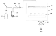
図2は、CVD装置の一例の概略構成を示すものである。CVD装置は、成膜空間を構成する真空チャンバ21と、当該真空チャンバ21内を所定の真空度とする真空排気機構22、真空チャンバ21内に原料ガスを供給する原料ガス供給手段23とから構成される。真空チャンバ21には、図示は省略するが、CVDの方式に応じて、例えば加熱手段、光源、高周波電源、ホットワイヤ等が設置される。
FIG. 2 shows a schematic configuration of an example of a CVD apparatus. The CVD apparatus includes a
原料ガス供給手段23には、通常は原料ガスを充填したタンク、ボンベ等が用いられるが、本発明では、常温で固体の原料物質を気化して成膜するため、原料ガス供給手段23として、キャリアガス源24、及び原料物質25を収容する原料容器26を用いている。原料容器26には、加熱手段が設けられ、これを加熱しながらキャリアガスを供給することで、前記原料物質25が気化してシャワーヘッド27を介して真空チャンバ21内へと導入される。導入された原料物質は、真空チャンバ21内で分解され、真空チャンバ21内に設置された磁石素体28の表面に堆積し、CVD膜が形成される。CVD膜を2元系合金、あるいは3元系以上の合金とする場合には、CVD膜を構成する金属の数だけ原料ガス供給手段23を並列に設置し、各金属元素の化合物を原料容器26内に収容する。なお、原料ガス供給手段23には、流量計29や調整バルブ30を設置して、原料ガスの供給量を制御可能とする。
As the source gas supply means 23, a tank filled with a source gas, a cylinder, or the like is usually used. However, in the present invention, since a solid source material is vaporized at room temperature to form a film, as the source gas supply means 23, A
CVD膜の成膜に際しては、磁石素体28の全面を均一なCVD膜で被覆する必要がある。したがって、磁石素体28を真空チャンバ21内で回転、振動等により撹拌しながらCVDによる成膜を行うことが好ましい。
When forming the CVD film, it is necessary to cover the entire surface of the
原料となる原料物質としては、βジケトン系有機金属錯体等を挙げることができる。具体的化合物としては、例えば耐候性表面被膜の場合、Ni等においてはβジケトン系有機金属錯体、Si等においては各種シラン化合物等を使用することができる。 Examples of the raw material used as a raw material include β-diketone organic metal complexes. As a specific compound, for example, in the case of a weather resistant surface coating, a β-diketone organometallic complex can be used for Ni or the like, and various silane compounds can be used for Si or the like.
回復用被膜の場合には、βジケトン系希土類元素有機金属錯体が使用可能であり、一般式R(DPM)3、R(HFA)3、R(FOD)3等が例示される。なお、前記一般式中、Rは希土類元素、DPMは2,2,6,6−テトラメチル−1,3,5−ヘプタンジオン(2,2,6,6-tetramethyl-1,3,5-heptanedione)、HFAは1,1,1,5,5,5−ヘキサフルオロ−2,4−ペンタンジオン(1,1,1,5,5,5,-hexafluoro-2,4-pentanedione)、FODは1,1,1,2,2,3,3−ヘプタフルオロ−7,7−ジメチル−4,6−オクタンジオン(1,1,1,2,2,3,3-heptafluoro-7,7-dimethyl-4,6-octanedione)である。あるいは、前記βジケトン系希土類元素有機金属錯体として、6−エチル−2,2−ジメチル−3,5−オクタンジオンを希土類元素の配位子とした有機希土類錯体等も使用可能である。
In the case of a recovery coating, a β-diketone rare earth element organometallic complex can be used, and general formulas R (DPM) 3 , R (HFA) 3 , R (FOD) 3 and the like are exemplified. In the above general formula, R is a rare earth element, and DPM is 2,2,6,6-tetramethyl-1,3,5-heptanedione (2,2,6,6-tetramethyl-1,3,5- heptanedione), HFA is 1,1,1,5,5,5-hexafluoro-2,4-pentanedione (1,1,1,5,5,5, -hexafluoro-2,4-pentanedione),
前記希土類化合物は、百数十℃以上の温度で加熱して気化させ、これを含んだ蒸気を真空チャンバ21内に供給する。あるいは、これら希土類化合物をテトラヒドロフラン(THF)等の溶媒に溶かして溶液とし、液体マスフローコントローラを使って真空チャンバ21内に輸液したり、ノズルから吹き付けることで供給することも可能である。
The rare earth compound is heated and vaporized at a temperature of hundreds of degrees Celsius or higher, and a vapor containing this is supplied into the
回復用被膜を2元系合金、あるいは3元系以上の合金とする場合、他の金属元素の化合物を原料として使用する必要があるが、例えばFe等の希土類元素以外の金属元素の場合にも、Fe(DPM)3等のβジケトン系有機金属錯体等、各種既存の有機金属化合物等を用いることで、原料供給が可能である。 When the recovery coating is made of a binary alloy, or a ternary alloy or more, it is necessary to use a compound of another metal element as a raw material, but also in the case of a metal element other than a rare earth element such as Fe. By using various existing organometallic compounds such as β-diketone organometallic complexes such as Fe (DPM) 3 , raw materials can be supplied.
前述のCVD法では、原料ガスの流量を制御することにより成膜される回復用被膜の組成を制御することができる。そこで、これを利用して回復用被膜の組成に分布を持たせることが可能である。先にも述べたように、前記回復用被膜において、磁石素体と接する内側部分においてNd、Prから選ばれる少なくとも1種の濃度が高く、これとは反対側の外側部分においてDy、Tbから選ばれる少なくとも1種の濃度が高くなるように組成分布を持たせることにより、DyやTbの使用量を削減することができ、製造コストを抑えることができる。 In the above-described CVD method, the composition of the recovery film formed can be controlled by controlling the flow rate of the source gas. Therefore, it is possible to give a distribution to the composition of the recovery film by utilizing this. As described above, in the recovery film, at least one concentration selected from Nd and Pr is high in the inner portion in contact with the magnet body, and selected from Dy and Tb in the outer portion on the opposite side. By providing the composition distribution so that at least one kind of concentration is increased, the amount of Dy and Tb used can be reduced, and the manufacturing cost can be reduced.
回復用被膜にこのような組成分布を持たせるには、先ずNd、Prから選ばれる少なくとも1種の希土類化合物を原料ガスとして供給し、Nd、あるいはPrを主体とするCVD膜を成膜する。次いで、原料ガスを切り替え、Dy、Tbから選ばれる少なくとも1種の希土類化合物を原料ガスとして供給し、Dy、あるいはTbを主体とするCVD膜を成膜する。これにより、前記組成分布を持った回復用被膜が成膜される。 In order to give such a composition distribution to the recovery film, first, at least one rare earth compound selected from Nd and Pr is supplied as a source gas, and a CVD film mainly composed of Nd or Pr is formed. Next, the source gas is switched, at least one rare earth compound selected from Dy and Tb is supplied as a source gas, and a CVD film mainly composed of Dy or Tb is formed. Thereby, the recovery film having the composition distribution is formed.
一方、ディッピング処理は、磁石素体を耐候性表面被膜の場合にはAl合金等の溶湯中に、また回復用被膜の場合には希土類元素を主体とする合金溶湯中に浸漬するだけでよく、極めて簡便な手法である。特に、回復用被膜の場合、使用する合金溶湯は、希土類元素を主体とするものであるが、希土類元素単体の溶湯であってもよいし、希土類元素を含む2元系合金、あるいは3元系以上の合金の溶湯であってもよい。ただし、加工劣化層の改質による効果を得るためには、希土類元素を50原子%以上含有していることが好ましい。また、磁石素体に含まれる希土類元素の割合よりも、合金溶湯に含まれる希土類元素の割合の方が大であることが好ましい。 On the other hand, in the dipping process, it is only necessary to immerse the magnet body in a molten alloy such as an Al alloy in the case of a weather resistant surface coating, or in a molten alloy mainly composed of rare earth elements in the case of a recovery coating, This is an extremely simple method. In particular, in the case of a recovery coating, the alloy melt used is mainly composed of rare earth elements, but may be a melt of a rare earth element alone, a binary alloy containing rare earth elements, or a ternary system. A molten metal of the above alloy may be used. However, in order to obtain the effect by the modification of the work deterioration layer, it is preferable to contain 50 atom% or more of rare earth elements. Moreover, it is preferable that the ratio of the rare earth element contained in the molten alloy is larger than the ratio of the rare earth element contained in the magnet body.
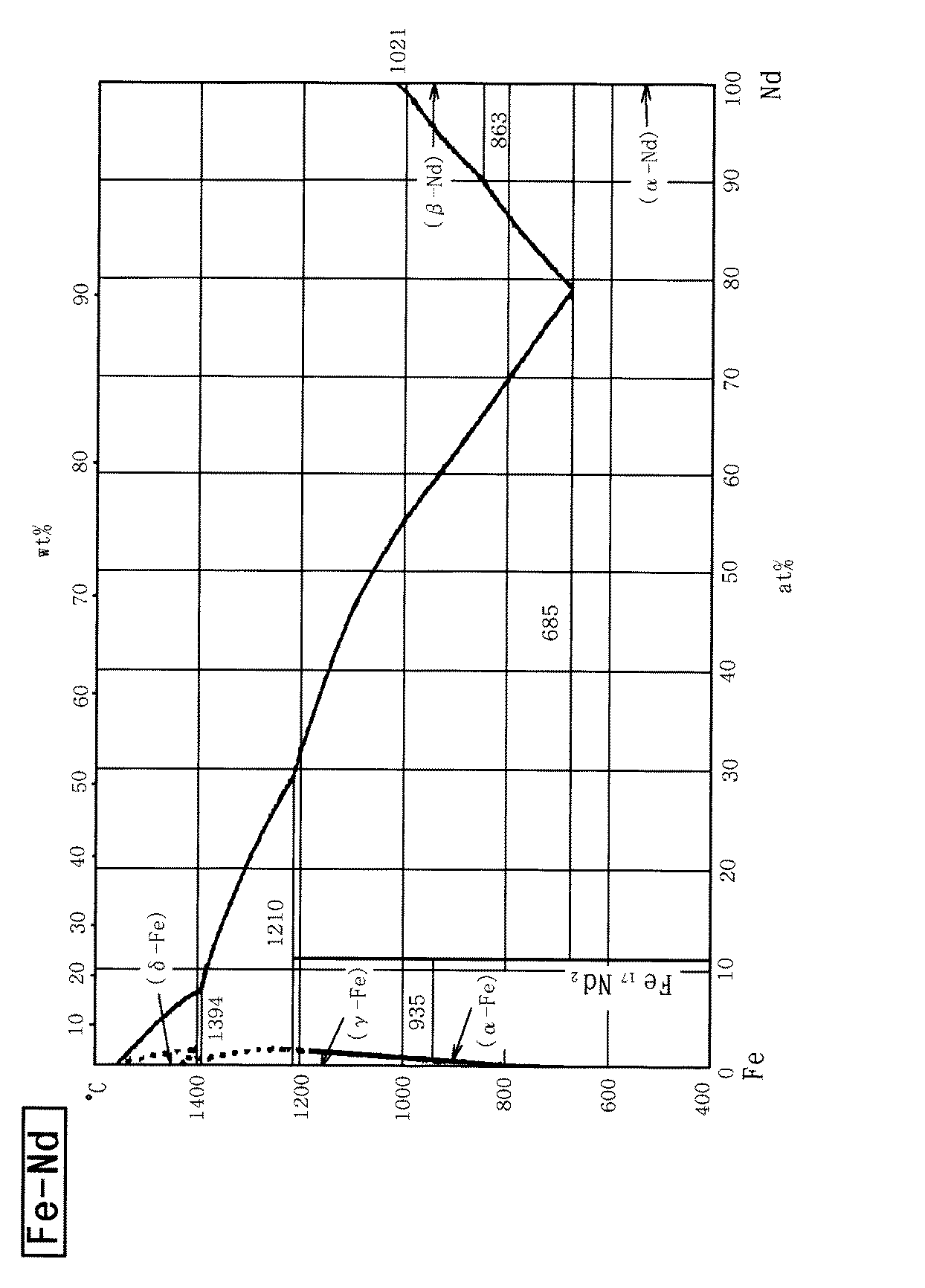
また、合金溶湯の融点は、あまり高すぎると磁石素体の焼結温度に近づき、磁石素体の特性を劣化させるおそれがあることから、1000℃以下とすることが好ましい。したがって、例えば回復用被膜の形成に用いる合金溶湯の組成は、この融点の観点から設定することも必要である。例えば、Dy−Fe系の状態図を図3に、Nd−Fe系の状態図を図4に示す。Dy−Fe系では、Dyが70原子%において融点が890℃まで下がっており、Dyが65原子%〜77原子%で融点1000℃以下が達成される。Nd−Fe系では、Ndが78原子%で融点685℃であり、Ndが55原子%以上で融点1000℃以下が達成される。 Further, if the melting point of the molten alloy is too high, the melting point approaches the sintering temperature of the magnet body and may deteriorate the characteristics of the magnet body, and therefore it is preferably set to 1000 ° C. or lower. Therefore, for example, the composition of the molten alloy used for forming the recovery coating must be set from the viewpoint of this melting point. For example, FIG. 3 shows a Dy—Fe phase diagram, and FIG. 4 shows a Nd—Fe phase diagram. In the Dy-Fe system, the melting point is lowered to 890 ° C. when Dy is 70 atomic%, and a melting point of 1000 ° C. or less is achieved when Dy is 65 atomic% to 77 atomic%. In the Nd—Fe system, Nd is 78 atomic% and the melting point is 685 ° C., and Nd is 55 atomic% or more and the melting point is 1000 ° C. or less.
ディッピング処理におけるディッピング時間は、10分間〜1時間程度である。ディッピング時間が短すぎると、表面改質効果が不十分となるおそれがある。ディッピング時間が長すぎると、生産性が低下し、磁石素体への熱的影響が大きくなるおそれもある。なお、ディッピング温度やディッピング時間を最適化すれば、時効処理を兼ねることもでき、製造工程をさらに簡略化することが可能である。 The dipping time in the dipping process is about 10 minutes to 1 hour. If the dipping time is too short, the surface modification effect may be insufficient. If the dipping time is too long, the productivity is lowered and the thermal influence on the magnet body may be increased. If the dipping temperature and dipping time are optimized, the aging treatment can be performed, and the manufacturing process can be further simplified.
前記いずれかの方法で磁石素体の表面に耐候性表面被膜、あるいは回復用被膜及び耐候性表面被膜を成膜した後、回復処理工程8で磁石素体の表面改質を行う。この回復処理工程は、例えば熱処理することによって行う。この場合の熱処理温度としては、600℃〜1100℃程度であるが、例えば回復用被膜を形成した後、耐候性表面被膜を形成した場合には、この回復処理のための熱処理を温度の異なる2段階の熱処理とすることも可能である。この場合、1段目の熱処理温度よりも2段目の熱処理温度が高くなるように設定することが好ましい。
After forming a weather-resistant surface coating, or a recovery coating and a weather-resistant surface coating on the surface of the magnet body by any of the above methods, the surface modification of the magnet body is performed in a
具体的には、回復用被膜において、1段目に固相反応が進む温度で熱処理し、2段目に液相が生じる温度で熱処理する。あるいは、1段目に被膜の融点未満の温度で熱処理し、2段目に被膜の融点以上の温度で熱処理する。 Specifically, in the recovery coating, heat treatment is performed at a temperature at which a solid phase reaction proceeds in the first stage, and heat treatment is performed at a temperature at which a liquid phase is generated in the second stage. Alternatively, the first stage is heat-treated at a temperature lower than the melting point of the film, and the second stage is heat-treated at a temperature higher than the melting point of the film.
前述の回復処理工程の後、耐候性表面被膜や回復用被膜によって被覆し表面改質した磁石素体に対して、時効処理を施すことが好ましい。時効工程9は、希土類磁石の保磁力Hcjを制御する上で重要な工程であり、例えば不活性ガス雰囲気中あるいは真空中で時効処理を施す。時効処理としては、例えば2段時効処理が好ましく、例えば1段目の時効処理工程では、800℃前後の温度で0.1〜3時間保持する。次いで、急冷し、2段目の時効処理工程では、550℃前後の温度で0.2〜3時間保持する。600℃近傍の熱処理で保磁力Hcjが大きく増加するため、時効処理を一段で行う場合には、600℃近傍、例えば450℃〜650℃での時効処理を施すとよい。また、通常の焼結磁石作成工程で行なわれる焼結工程の直後に時効処理を行っておくことも当然可能である。 After the above-described recovery treatment step, it is preferable to apply an aging treatment to the magnet body that has been coated with a weather-resistant surface coating or a recovery coating and whose surface has been modified. The aging step 9 is an important step in controlling the coercive force Hcj of the rare earth magnet, and for example, an aging treatment is performed in an inert gas atmosphere or in a vacuum. As the aging treatment, for example, a two-stage aging treatment is preferable. For example, in the first aging treatment step, the temperature is maintained at a temperature of about 800 ° C. for 0.1 to 3 hours. Next, it is rapidly cooled and maintained at a temperature of around 550 ° C. for 0.2 to 3 hours in the second stage aging treatment step. Since the coercive force Hcj is greatly increased by heat treatment in the vicinity of 600 ° C., when aging treatment is performed in one step, it is preferable to perform aging treatment in the vicinity of 600 ° C., for example, 450 ° C. to 650 ° C. Of course, it is also possible to carry out an aging treatment immediately after the sintering step performed in a normal sintered magnet production step.
なお、前述の通り、回復処理工程8において、各段階の熱処理温度や熱処理時間を最適化して時効処理を兼ねるようにした場合には、前記時効工程10の一部、あるいは全部を省略することも可能である。
As described above, in the
通常のプロセスでは、前記時効事項9の後、清浄化工程において表面に形成された酸化被膜の清浄化を行う必要があるが、本発明では、予め耐候性表面被膜が形成され、熱処理工程等において酸化被膜が回復処理した磁石素体面上に形成されることがないので省略することが可能である。勿論、耐食性被膜を重ねる場合、耐候性表面被膜上を若干の清浄化を行うことを妨げるものではない。 In a normal process, after the aging item 9, it is necessary to clean the oxide film formed on the surface in the cleaning process. However, in the present invention, a weather-resistant surface film is formed in advance and the heat treatment process or the like is performed. Since the oxide film is not formed on the magnet body surface subjected to the recovery treatment, it can be omitted. Of course, when the corrosion-resistant coatings are stacked, it does not prevent slight cleaning on the weather-resistant surface coating.
また、通常のプロセスでは、最後に、耐食性被膜形成工程により耐食性被膜を形成して希土類磁石を完成するが、本発明では、予め耐候性表面被膜が形成されてるので、この工程も省略することが可能である。ただし、例えば、先に形成した耐候性表面被膜の膜厚が不足する場合等には、さらに耐食性被膜を重ねて形成することも可能である。この場合の耐食性被膜としては、磁石素体の酸化を防ぐ保護膜として機能するものであれば材料は問わないが、例えば前記耐候性表面被膜と同様、Ni、Si、Al合金、Au、Ptから選ばれる少なくとも1種の被膜等を挙げることができる。前記耐食性被膜の成膜方法も任意であるが、先の耐候性表面被膜をCVD法により形成した場合、耐食性被膜もCVD法により形成すれば、工程の簡略化を図ることができる。 Further, in a normal process, finally, a corrosion-resistant film is formed by a corrosion-resistant film forming step to complete a rare earth magnet. However, in the present invention, since a weather-resistant surface film is formed in advance, this step may be omitted. Is possible. However, for example, when the film thickness of the previously formed weather resistant surface coating is insufficient, it is possible to further form a corrosion resistant coating. The corrosion-resistant coating in this case may be any material as long as it functions as a protective film that prevents the magnet body from being oxidized. For example, as with the weather-resistant surface coating, Ni, Si, Al alloy, Au, and Pt are used. Examples thereof include at least one selected film. The method for forming the corrosion-resistant film is arbitrary, but when the weather-resistant surface film is formed by the CVD method, the process can be simplified if the corrosion-resistant film is also formed by the CVD method.
次に、本発明の具体的な実施例について、実験結果を基に説明する。
<実験1>
先ず、NdFeB系焼結磁石として、Nd24.5重量%、Pr3.2重量%、Dy2.5重量%、Co3重量%、B1重量%、Ga0.35重量%、残部Feからなる希土類焼結磁石(磁石素材)を用意した。これを試料1(比較例)とする。
Next, specific examples of the present invention will be described based on experimental results.
<Experiment 1>
First, as a NdFeB-based sintered magnet, a rare earth sintered magnet comprising Nd 24.5 wt%, Pr 3.2 wt%, Dy 2.5 wt%,
次に、この希土類焼結磁石を機械加工によって切断し、10mm×10mm×0.5mm(厚さ)の磁石素体とした。これを試料2(比較例)とする。 Next, the rare earth sintered magnet was cut by machining to obtain a magnet body of 10 mm × 10 mm × 0.5 mm (thickness). This is designated as Sample 2 (Comparative Example).
さらに、切断した磁石素体の表面に厚さ1μmのCu被膜を成膜し、次いで厚さ7μmのNi被膜をCVD法により成膜した。その後、1000℃、20分間の熱処理(回復処理)を行い、800℃で25分間、及び600℃で60分間の時効処理を行った。これを試料3(実施例)とする。 Furthermore, a Cu film having a thickness of 1 μm was formed on the surface of the cut magnet body, and then a Ni film having a thickness of 7 μm was formed by a CVD method. Thereafter, heat treatment (recovery treatment) was performed at 1000 ° C. for 20 minutes, and an aging treatment was performed at 800 ° C. for 25 minutes and 600 ° C. for 60 minutes. This is designated as Sample 3 (Example).
一方、切断した磁石素体の表面にPVD法により回復用被膜を形成し、引き続きPVD法により厚さ7μmのNi被膜を成膜した。回復用被膜の組成は、Nd30原子%、Pr10原子%、Dy50原子%、残部Feであり、約4μm成膜した。その後、1000℃、20分間の熱処理(回復処理)を行い、600℃で2時間の時効処理を行った。これを試料4(実施例)とする。
On the other hand, a recovery coating was formed on the surface of the cut magnet body by the PVD method, and subsequently a Ni coating having a thickness of 7 μm was formed by the PVD method. The composition of the recovery film was
同様に、切断した磁石素体の表面にCVD法により回復用被膜を形成し、引き続きCVD法により厚さ7μmのNi被膜を成膜した。回復用被膜の組成は、Nd30原子%、Pr10原子%、Dy50原子%、残部Feであり、約4μm成膜した。その後、1050℃、15分間の熱処理(回復処理)を行い、600℃で2時間の時効処理を行った。これを試料5(実施例)とする。
Similarly, a recovery film was formed on the surface of the cut magnet body by the CVD method, and subsequently a Ni film having a thickness of 7 μm was formed by the CVD method. The composition of the recovery film was
作製した各希土類磁石について、残留磁束密度Br、保磁力iHc、角型性を測定した。磁石特性[残留磁束密度Br、保磁力iHc、]の測定は、B−Hトレーサーを用いて行った。角型性は、B−Hループにおいて、磁化Bが残留磁化Brより10%低下した点での磁界Hkと、磁化Bがゼロとなる点での磁界(保磁力iHc)との比率(Hk/iHc)より算出した。結果を表1に示す。 About each produced rare earth magnet, residual magnetic flux density Br, coercive force iHc, and squareness were measured. Magnet characteristics [residual magnetic flux density Br, coercive force iHc,] were measured using a BH tracer. In the BH loop, the squareness is the ratio (Hk /) of the magnetic field Hk at the point where the magnetization B is 10% lower than the residual magnetization Br and the magnetic field (coercive force iHc) at which the magnetization B becomes zero. iHc). The results are shown in Table 1.
この表1から明らかなように、耐候性表面被膜(Ni被膜)や希土類元素を主体とする回復用被膜の形成及び回復処理により、加工前の磁石素材(試料1)の磁気特性に匹敵する磁石特性を有する希土類磁石が得られることがわかる。機械加工を施した磁石素体(試料2)は、そのままでは磁気特性の劣化が大きい。 As is clear from Table 1, a magnet comparable to the magnetic properties of the magnet material (sample 1) before processing by forming and recovering a weather-resistant surface coating (Ni coating) or a recovery coating mainly composed of rare earth elements It turns out that the rare earth magnet which has the characteristic is obtained. The machined magnet body (sample 2) is greatly deteriorated in magnetic properties as it is.
また、試料3、4,5について、Ni被膜を形成しないで同様に希土類磁石の作製を試みたが、この場合には、熱処理後に表面酸化被膜が見られた。また、試料5では、Ni被膜を形成しない場合に変形も認められた。なお、試料3,4,5の端面を研磨し、被膜と磁石素体との界面を観察したところ、いずれも拡散層が見られた。
Further, for
<実験2>
先ず、NdFeB系焼結磁石として、Nd25.5重量%、Pr4.7重量%、Al0.2重量%、B1重量%、Cu0.06重量%、Co1.5重量%、残部Feからなる希土類焼結磁石(磁石素材)を用意した。これを試料6(比較例)とする。
<
First, as a NdFeB-based sintered magnet, rare earth sintered comprising Nd 25.5 wt%, Pr 4.7 wt%, Al 0.2 wt%, B 1 wt%, Cu 0.06 wt%, Co 1.5 wt%, and the balance Fe. A magnet (magnet material) was prepared. This is designated as Sample 6 (Comparative Example).
次に、この希土類焼結磁石を機械加工によって切断し、10mm×10mm×0.5mm(厚さ)の磁石素体とした。これを試料7(比較例)とする。 Next, the rare earth sintered magnet was cut by machining to obtain a magnet body of 10 mm × 10 mm × 0.5 mm (thickness). This is designated as Sample 7 (Comparative Example).
さらに、切断した磁石素体の表面にディッピング法(900℃、10分間)により回復用被膜を形成し、引き続きCVD法により厚さ5μmのNi被膜を成膜した。回復用被膜の組成は、Nd50原子%、Pr15原子%、Dy15原子%、残部Feであり、約4μm成膜した。その後、870℃、10分間の熱処理(回復処理)を行い、600℃で30分間の時効処理を行った。これを試料8(実施例)とする。
Further, a recovery film was formed on the surface of the cut magnet body by dipping (900 ° C., 10 minutes), and subsequently a Ni film having a thickness of 5 μm was formed by CVD. The composition of the recovery film was
作製した各希土類磁石について、残留磁束密度Br、保磁力iHc、角型性を測定した。各特性の測定は、先の実験1と同様にして行なった。結果を表2に示す。 About each produced rare earth magnet, residual magnetic flux density Br, coercive force iHc, and squareness were measured. Each characteristic was measured in the same manner as in Experiment 1 above. The results are shown in Table 2.
この表2から明らかなように、本実験においても、耐候性表面被膜(Ni被膜)及び希土類元素を主体とする回復用被膜の形成と回復処理により、加工前の磁石素材(試料1)の磁気特性に匹敵する磁石特性を有する希土類磁石が得られることがわかる。また、試料8について、Ni被膜を形成しないで同様に希土類磁石の作製を試みたが、この場合には、熱処理後に表面酸化被膜が見られた。
As is apparent from Table 2, in this experiment as well, the magnetic properties of the magnet material (sample 1) before processing were formed by the formation and recovery treatment of the weather-resistant surface coating (Ni coating) and the recovery coating mainly composed of rare earth elements. It can be seen that a rare earth magnet having magnet characteristics comparable to the characteristics can be obtained. In addition, for the
1 合金化工程、2 粗粉砕工程、3 微粉砕工程、4 磁場中成形工程、5 焼結工程、6 機械加工工程、7 被膜形成工程、8 回復処理工程、9 時効工程、21 真空チャンバ、22 真空排気機構、23 原料ガス供給手段、24 キャリアガス源、25 希土類化合物、26 原料容器、27 シャワーヘッド、28 磁石素体、29 流量計、30 調整バルブ DESCRIPTION OF SYMBOLS 1 Alloying process, 2 Coarse grinding process, 3 Fine grinding process, 4 Magnetic field forming process, 5 Sintering process, 6 Machining process, 7 Film formation process, 8 Recovery process, 9 Aging process, 21 Vacuum chamber, 22 Vacuum exhaust mechanism, 23 source gas supply means, 24 carrier gas source, 25 rare earth compound, 26 source container, 27 shower head, 28 magnet body, 29 flow meter, 30 adjustment valve
Claims (23)
Priority Applications (1)
| Application Number | Priority Date | Filing Date | Title |
|---|---|---|---|
| JP2004107998A JP4577486B2 (en) | 2004-03-31 | 2004-03-31 | Rare earth magnet and method for producing rare earth magnet |
Applications Claiming Priority (1)
| Application Number | Priority Date | Filing Date | Title |
|---|---|---|---|
| JP2004107998A JP4577486B2 (en) | 2004-03-31 | 2004-03-31 | Rare earth magnet and method for producing rare earth magnet |
Publications (2)
| Publication Number | Publication Date |
|---|---|
| JP2005294558A true JP2005294558A (en) | 2005-10-20 |
| JP4577486B2 JP4577486B2 (en) | 2010-11-10 |
Family
ID=35327147
Family Applications (1)
| Application Number | Title | Priority Date | Filing Date |
|---|---|---|---|
| JP2004107998A Expired - Fee Related JP4577486B2 (en) | 2004-03-31 | 2004-03-31 | Rare earth magnet and method for producing rare earth magnet |
Country Status (1)
| Country | Link |
|---|---|
| JP (1) | JP4577486B2 (en) |
Cited By (18)
| Publication number | Priority date | Publication date | Assignee | Title |
|---|---|---|---|---|
| WO2006085581A1 (en) * | 2005-02-10 | 2006-08-17 | Neomax Co., Ltd. | Ultra small rare earth magnet and method for manufacturing same |
| WO2006112403A1 (en) * | 2005-04-15 | 2006-10-26 | Hitachi Metals, Ltd. | Rare earth sintered magnet and process for producing the same |
| WO2007077809A1 (en) * | 2005-12-28 | 2007-07-12 | Hitachi Metals, Ltd. | Rare earth magnet and method for producing same |
| JP2007273863A (en) * | 2006-03-31 | 2007-10-18 | Tdk Corp | Magnet member |
| JP2007287875A (en) * | 2006-04-14 | 2007-11-01 | Shin Etsu Chem Co Ltd | Method for producing rare earth permanent magnet material |
| WO2008139690A1 (en) * | 2007-05-01 | 2008-11-20 | Intermetallics Co., Ltd. | Process for production of ndfeb sintered magnets |
| WO2008140054A1 (en) * | 2007-05-09 | 2008-11-20 | Hitachi Metals, Ltd. | R-Fe-B SINTERED MAGNET PROVIDED ON ITS SURFACE WITH VAPOR DEPOSITION COATING OF ALUMINUM OR ITS ALLOY AND PROCESS FOR PRODUCING THE SAME |
| JP2009289994A (en) * | 2008-05-29 | 2009-12-10 | Tdk Corp | Process for producing magnet |
| JP2011205022A (en) * | 2010-03-26 | 2011-10-13 | Tdk Corp | Rare-earth sintered magnet, method of manufacturing the same, and rotating machine |
| US8038807B2 (en) | 2006-01-31 | 2011-10-18 | Hitachi Metals, Ltd. | R-Fe-B rare-earth sintered magnet and process for producing the same |
| JP2013042152A (en) * | 2012-09-25 | 2013-02-28 | Tdk Corp | Magnet manufacturing method |
| JP2014209560A (en) * | 2013-03-29 | 2014-11-06 | 大同特殊鋼株式会社 | Method for manufacturing rare earth-iron-boron based magnet |
| WO2015121915A1 (en) * | 2014-02-12 | 2015-08-20 | 日東電工株式会社 | Rare earth permanent magnet and production method for rare earth permanent magnet |
| KR101602789B1 (en) * | 2014-11-27 | 2016-03-24 | 부산대학교 산학협력단 | NdFeB BASED MAGNET AND METHOD OF THE NdFeB BASED MAGNET USING WETTING COATING |
| JPWO2014010418A1 (en) * | 2012-07-12 | 2016-06-23 | 日産自動車株式会社 | Manufacturing method of sintered magnet |
| US20210317566A1 (en) * | 2018-12-29 | 2021-10-14 | Sanvac (Beijing) Magnetics Co., Ltd. | Coating machine and coating method |
| JP2022516380A (en) * | 2019-02-01 | 2022-02-25 | 天津三環楽喜新材料有限公司 | Rare earth diffusing magnet manufacturing method and rare earth diffusing magnet |
| JP2023141524A (en) * | 2022-03-24 | 2023-10-05 | 株式会社プロテリアル | Manufacturing method of RTB based sintered magnet |
Citations (12)
| Publication number | Priority date | Publication date | Assignee | Title |
|---|---|---|---|---|
| JPS61281850A (en) * | 1985-06-07 | 1986-12-12 | Sumitomo Special Metals Co Ltd | Permanent magnet material |
| JPS62120002A (en) * | 1985-11-20 | 1987-06-01 | Sumitomo Special Metals Co Ltd | Permanent magnet with excellent corrosion resistance |
| JPS62188745A (en) * | 1986-02-13 | 1987-08-18 | Sumitomo Special Metals Co Ltd | Permanent magnet material and its production |
| JPS62192566A (en) * | 1986-02-18 | 1987-08-24 | Sumitomo Special Metals Co Ltd | Permanent magnet material and its production |
| JPS63453A (en) * | 1986-06-20 | 1988-01-05 | Tohoku Metal Ind Ltd | Oxidation resistant permanent magnet material and its production |
| JPS6442805A (en) * | 1987-08-10 | 1989-02-15 | Shinetsu Chemical Co | Rare earth permanent magnet with high corrosion resistance |
| JPH01117303A (en) * | 1987-10-30 | 1989-05-10 | Taiyo Yuden Co Ltd | Permanent magnet |
| JPH04144102A (en) * | 1990-10-04 | 1992-05-18 | Hitachi Metals Ltd | Permanent magnet |
| JPH05109519A (en) * | 1991-10-18 | 1993-04-30 | Kobe Steel Ltd | High corrosion resistant rare earth magnet and manufacture thereof |
| JPH07176443A (en) * | 1993-12-20 | 1995-07-14 | Daido Steel Co Ltd | Method for manufacturing anisotropic rare earth magnet |
| JPH08264310A (en) * | 1995-03-24 | 1996-10-11 | Hitachi Metals Ltd | Manufacture of rare earth-iron-boron permanent magnet |
| JPH0945567A (en) * | 1995-07-27 | 1997-02-14 | Hitachi Metals Ltd | Rare earth-iron-boron permanent magnet manufacturing method |
-
2004
- 2004-03-31 JP JP2004107998A patent/JP4577486B2/en not_active Expired - Fee Related
Patent Citations (12)
| Publication number | Priority date | Publication date | Assignee | Title |
|---|---|---|---|---|
| JPS61281850A (en) * | 1985-06-07 | 1986-12-12 | Sumitomo Special Metals Co Ltd | Permanent magnet material |
| JPS62120002A (en) * | 1985-11-20 | 1987-06-01 | Sumitomo Special Metals Co Ltd | Permanent magnet with excellent corrosion resistance |
| JPS62188745A (en) * | 1986-02-13 | 1987-08-18 | Sumitomo Special Metals Co Ltd | Permanent magnet material and its production |
| JPS62192566A (en) * | 1986-02-18 | 1987-08-24 | Sumitomo Special Metals Co Ltd | Permanent magnet material and its production |
| JPS63453A (en) * | 1986-06-20 | 1988-01-05 | Tohoku Metal Ind Ltd | Oxidation resistant permanent magnet material and its production |
| JPS6442805A (en) * | 1987-08-10 | 1989-02-15 | Shinetsu Chemical Co | Rare earth permanent magnet with high corrosion resistance |
| JPH01117303A (en) * | 1987-10-30 | 1989-05-10 | Taiyo Yuden Co Ltd | Permanent magnet |
| JPH04144102A (en) * | 1990-10-04 | 1992-05-18 | Hitachi Metals Ltd | Permanent magnet |
| JPH05109519A (en) * | 1991-10-18 | 1993-04-30 | Kobe Steel Ltd | High corrosion resistant rare earth magnet and manufacture thereof |
| JPH07176443A (en) * | 1993-12-20 | 1995-07-14 | Daido Steel Co Ltd | Method for manufacturing anisotropic rare earth magnet |
| JPH08264310A (en) * | 1995-03-24 | 1996-10-11 | Hitachi Metals Ltd | Manufacture of rare earth-iron-boron permanent magnet |
| JPH0945567A (en) * | 1995-07-27 | 1997-02-14 | Hitachi Metals Ltd | Rare earth-iron-boron permanent magnet manufacturing method |
Cited By (37)
| Publication number | Priority date | Publication date | Assignee | Title |
|---|---|---|---|---|
| WO2006085581A1 (en) * | 2005-02-10 | 2006-08-17 | Neomax Co., Ltd. | Ultra small rare earth magnet and method for manufacturing same |
| JPWO2006085581A1 (en) * | 2005-02-10 | 2008-06-26 | 日立金属株式会社 | Ultra-small rare earth magnet and manufacturing method thereof |
| JPWO2006112403A1 (en) * | 2005-04-15 | 2008-12-11 | 日立金属株式会社 | Rare earth sintered magnet and manufacturing method thereof |
| WO2006112403A1 (en) * | 2005-04-15 | 2006-10-26 | Hitachi Metals, Ltd. | Rare earth sintered magnet and process for producing the same |
| JP2011159983A (en) * | 2005-04-15 | 2011-08-18 | Hitachi Metals Ltd | Rare earth sintered magnet and process for producing the same |
| JP4748163B2 (en) * | 2005-04-15 | 2011-08-17 | 日立金属株式会社 | Rare earth sintered magnet and manufacturing method thereof |
| US7655325B2 (en) | 2005-12-28 | 2010-02-02 | Hitachi Metals, Ltd. | Rare earth magnet and method for producing same |
| JP4915349B2 (en) * | 2005-12-28 | 2012-04-11 | 日立金属株式会社 | Rare earth magnet and manufacturing method thereof |
| WO2007077809A1 (en) * | 2005-12-28 | 2007-07-12 | Hitachi Metals, Ltd. | Rare earth magnet and method for producing same |
| US8038807B2 (en) | 2006-01-31 | 2011-10-18 | Hitachi Metals, Ltd. | R-Fe-B rare-earth sintered magnet and process for producing the same |
| JP4831074B2 (en) * | 2006-01-31 | 2011-12-07 | 日立金属株式会社 | R-Fe-B rare earth sintered magnet and method for producing the same |
| JP2011223007A (en) * | 2006-01-31 | 2011-11-04 | Hitachi Metals Ltd | R-Fe-B-BASED RARE-EARTH SINTERED MAGNET AND METHOD FOR PRODUCING THE SAME |
| JP2007273863A (en) * | 2006-03-31 | 2007-10-18 | Tdk Corp | Magnet member |
| JP2007287875A (en) * | 2006-04-14 | 2007-11-01 | Shin Etsu Chem Co Ltd | Method for producing rare earth permanent magnet material |
| JPWO2008139690A1 (en) * | 2007-05-01 | 2010-07-29 | インターメタリックス株式会社 | NdFeB-based sintered magnet manufacturing method |
| US8801870B2 (en) | 2007-05-01 | 2014-08-12 | Intermetallics Co., Ltd. | Method for making NdFeB sintered magnet |
| JP5363314B2 (en) * | 2007-05-01 | 2013-12-11 | インターメタリックス株式会社 | NdFeB-based sintered magnet manufacturing method |
| WO2008139690A1 (en) * | 2007-05-01 | 2008-11-20 | Intermetallics Co., Ltd. | Process for production of ndfeb sintered magnets |
| CN101641750B (en) * | 2007-05-01 | 2012-07-11 | 因太金属株式会社 | Process for production of ndfeb sintered magnets |
| KR101397328B1 (en) * | 2007-05-01 | 2014-05-19 | 인터메탈릭스 가부시키가이샤 | Process for production of NdFeB sintered magnets |
| WO2008140054A1 (en) * | 2007-05-09 | 2008-11-20 | Hitachi Metals, Ltd. | R-Fe-B SINTERED MAGNET PROVIDED ON ITS SURFACE WITH VAPOR DEPOSITION COATING OF ALUMINUM OR ITS ALLOY AND PROCESS FOR PRODUCING THE SAME |
| US8163106B2 (en) | 2007-05-09 | 2012-04-24 | Hitachi Metals, Ltd. | R-Fe-B based sintered magnet having on the surface thereof vapor deposited film of aluminum or alloy thereof, and method for producing the same |
| JP5263153B2 (en) * | 2007-05-09 | 2013-08-14 | 日立金属株式会社 | R-Fe-B based sintered magnet having a deposited film of aluminum or its alloy on the surface and method for producing the same |
| JP2009289994A (en) * | 2008-05-29 | 2009-12-10 | Tdk Corp | Process for producing magnet |
| JP2011205022A (en) * | 2010-03-26 | 2011-10-13 | Tdk Corp | Rare-earth sintered magnet, method of manufacturing the same, and rotating machine |
| US11515086B2 (en) | 2012-07-12 | 2022-11-29 | Nissan Motor Co., Ltd. | Method for manufacturing sintered magnet |
| JPWO2014010418A1 (en) * | 2012-07-12 | 2016-06-23 | 日産自動車株式会社 | Manufacturing method of sintered magnet |
| JP2013042152A (en) * | 2012-09-25 | 2013-02-28 | Tdk Corp | Magnet manufacturing method |
| JP2014209560A (en) * | 2013-03-29 | 2014-11-06 | 大同特殊鋼株式会社 | Method for manufacturing rare earth-iron-boron based magnet |
| WO2015121915A1 (en) * | 2014-02-12 | 2015-08-20 | 日東電工株式会社 | Rare earth permanent magnet and production method for rare earth permanent magnet |
| KR101602789B1 (en) * | 2014-11-27 | 2016-03-24 | 부산대학교 산학협력단 | NdFeB BASED MAGNET AND METHOD OF THE NdFeB BASED MAGNET USING WETTING COATING |
| US20210317566A1 (en) * | 2018-12-29 | 2021-10-14 | Sanvac (Beijing) Magnetics Co., Ltd. | Coating machine and coating method |
| US11920236B2 (en) * | 2018-12-29 | 2024-03-05 | Sanvac (Beijing) Magnetics Co., Ltd. | Coating machine and coating method |
| JP2022516380A (en) * | 2019-02-01 | 2022-02-25 | 天津三環楽喜新材料有限公司 | Rare earth diffusing magnet manufacturing method and rare earth diffusing magnet |
| JP7371108B2 (en) | 2019-02-01 | 2023-10-30 | 天津三環楽喜新材料有限公司 | Rare earth diffusion magnet manufacturing method and rare earth diffusion magnet |
| JP2023141524A (en) * | 2022-03-24 | 2023-10-05 | 株式会社プロテリアル | Manufacturing method of RTB based sintered magnet |
| JP7800248B2 (en) | 2022-03-24 | 2026-01-16 | 株式会社プロテリアル | Method for manufacturing RTB based sintered magnet |
Also Published As
| Publication number | Publication date |
|---|---|
| JP4577486B2 (en) | 2010-11-10 |
Similar Documents
| Publication | Publication Date | Title |
|---|---|---|
| JP4577486B2 (en) | Rare earth magnet and method for producing rare earth magnet | |
| JP6089535B2 (en) | R-T-B sintered magnet | |
| JP5477282B2 (en) | R-T-B system sintered magnet and manufacturing method thereof | |
| EP1970924B1 (en) | Rare earth permanent magnets and their preparation | |
| CN101652820B (en) | R-fe-b anisotropic sintered magnet | |
| JP4962198B2 (en) | R-Fe-B rare earth sintered magnet and method for producing the same | |
| EP2797086B1 (en) | R-T-B Rare earth sintered magnet and method of manufacturing the same | |
| JP5598465B2 (en) | R-T-B-M alloy for sintered magnet and method for producing the same | |
| JP5348124B2 (en) | Method for producing R-Fe-B rare earth sintered magnet and rare earth sintered magnet produced by the method | |
| WO2007102391A1 (en) | R-Fe-B RARE EARTH SINTERED MAGNET AND METHOD FOR PRODUCING SAME | |
| JP2017147427A (en) | R-Fe-B sintered magnet and method for producing the same | |
| TW201308368A (en) | Rare earth permanent magnet and manufacturing method thereof | |
| EP2892064A1 (en) | Production method for rare earth permanent magnet | |
| JP2011086830A (en) | R-Fe-B-BASED RARE EARTH SINTERED MAGNET AND METHOD OF PRODUCING THE SAME | |
| JP2012079726A (en) | Production method of alloy for r-t-b-m based sintered magnet and production method of r-t-b-m based sintered magnet | |
| JP5146552B2 (en) | R-Fe-B rare earth sintered magnet and method for producing the same | |
| EP2892063A1 (en) | Production method for rare earth permanent magnet | |
| JP4433282B2 (en) | Rare earth magnet manufacturing method and manufacturing apparatus | |
| JP2005285859A (en) | Rare-earth magnet and its manufacturing method | |
| JP4605437B2 (en) | Rare earth magnet manufacturing method | |
| JP2005285861A (en) | Method of manufacturing rare-earth magnet | |
| JP2016169438A (en) | R-t-b-based rare earth sintered magnet and alloy for r-t-b-based rare earth sintered magnet | |
| JP4415681B2 (en) | Rare earth sintered magnet and manufacturing method thereof | |
| JP2005197299A (en) | Rare earth sintered magnet and manufacturing method thereof | |
| JP4076080B2 (en) | Rare earth permanent magnet manufacturing method |
Legal Events
| Date | Code | Title | Description |
|---|---|---|---|
| A621 | Written request for application examination |
Free format text: JAPANESE INTERMEDIATE CODE: A621 Effective date: 20070115 |
|
| A977 | Report on retrieval |
Free format text: JAPANESE INTERMEDIATE CODE: A971007 Effective date: 20090414 |
|
| A131 | Notification of reasons for refusal |
Free format text: JAPANESE INTERMEDIATE CODE: A131 Effective date: 20090423 |
|
| A521 | Request for written amendment filed |
Free format text: JAPANESE INTERMEDIATE CODE: A523 Effective date: 20090622 |
|
| A131 | Notification of reasons for refusal |
Free format text: JAPANESE INTERMEDIATE CODE: A131 Effective date: 20091208 |
|
| A521 | Request for written amendment filed |
Free format text: JAPANESE INTERMEDIATE CODE: A523 Effective date: 20100205 |
|
| TRDD | Decision of grant or rejection written | ||
| A01 | Written decision to grant a patent or to grant a registration (utility model) |
Free format text: JAPANESE INTERMEDIATE CODE: A01 Effective date: 20100728 |
|
| A01 | Written decision to grant a patent or to grant a registration (utility model) |
Free format text: JAPANESE INTERMEDIATE CODE: A01 |
|
| A61 | First payment of annual fees (during grant procedure) |
Free format text: JAPANESE INTERMEDIATE CODE: A61 Effective date: 20100810 |
|
| FPAY | Renewal fee payment (event date is renewal date of database) |
Free format text: PAYMENT UNTIL: 20130903 Year of fee payment: 3 |
|
| R150 | Certificate of patent or registration of utility model |
Ref document number: 4577486 Country of ref document: JP Free format text: JAPANESE INTERMEDIATE CODE: R150 Free format text: JAPANESE INTERMEDIATE CODE: R150 |
|
| LAPS | Cancellation because of no payment of annual fees |