JP6089535B2 - R-T-B sintered magnet - Google Patents
R-T-B sintered magnet Download PDFInfo
- Publication number
- JP6089535B2 JP6089535B2 JP2012212333A JP2012212333A JP6089535B2 JP 6089535 B2 JP6089535 B2 JP 6089535B2 JP 2012212333 A JP2012212333 A JP 2012212333A JP 2012212333 A JP2012212333 A JP 2012212333A JP 6089535 B2 JP6089535 B2 JP 6089535B2
- Authority
- JP
- Japan
- Prior art keywords
- main phase
- mass
- sintered magnet
- alloy
- hcj
- Prior art date
- Legal status (The legal status is an assumption and is not a legal conclusion. Google has not performed a legal analysis and makes no representation as to the accuracy of the status listed.)
- Active
Links
Images


Classifications
-
- H—ELECTRICITY
- H01—ELECTRIC ELEMENTS
- H01F—MAGNETS; INDUCTANCES; TRANSFORMERS; SELECTION OF MATERIALS FOR THEIR MAGNETIC PROPERTIES
- H01F1/00—Magnets or magnetic bodies characterised by the magnetic materials therefor; Selection of materials for their magnetic properties
- H01F1/01—Magnets or magnetic bodies characterised by the magnetic materials therefor; Selection of materials for their magnetic properties of inorganic materials
- H01F1/03—Magnets or magnetic bodies characterised by the magnetic materials therefor; Selection of materials for their magnetic properties of inorganic materials characterised by their coercivity
- H01F1/032—Magnets or magnetic bodies characterised by the magnetic materials therefor; Selection of materials for their magnetic properties of inorganic materials characterised by their coercivity of hard-magnetic materials
- H01F1/04—Magnets or magnetic bodies characterised by the magnetic materials therefor; Selection of materials for their magnetic properties of inorganic materials characterised by their coercivity of hard-magnetic materials metals or alloys
- H01F1/047—Alloys characterised by their composition
- H01F1/053—Alloys characterised by their composition containing rare earth metals
- H01F1/0536—Alloys characterised by their composition containing rare earth metals sintered
-
- C—CHEMISTRY; METALLURGY
- C22—METALLURGY; FERROUS OR NON-FERROUS ALLOYS; TREATMENT OF ALLOYS OR NON-FERROUS METALS
- C22C—ALLOYS
- C22C19/00—Alloys based on nickel or cobalt
- C22C19/07—Alloys based on nickel or cobalt based on cobalt
-
- C—CHEMISTRY; METALLURGY
- C22—METALLURGY; FERROUS OR NON-FERROUS ALLOYS; TREATMENT OF ALLOYS OR NON-FERROUS METALS
- C22C—ALLOYS
- C22C38/00—Ferrous alloys, e.g. steel alloys
- C22C38/001—Ferrous alloys, e.g. steel alloys containing N
-
- C—CHEMISTRY; METALLURGY
- C22—METALLURGY; FERROUS OR NON-FERROUS ALLOYS; TREATMENT OF ALLOYS OR NON-FERROUS METALS
- C22C—ALLOYS
- C22C38/00—Ferrous alloys, e.g. steel alloys
- C22C38/005—Ferrous alloys, e.g. steel alloys containing rare earths, i.e. Sc, Y, Lanthanides
-
- C—CHEMISTRY; METALLURGY
- C22—METALLURGY; FERROUS OR NON-FERROUS ALLOYS; TREATMENT OF ALLOYS OR NON-FERROUS METALS
- C22C—ALLOYS
- C22C38/00—Ferrous alloys, e.g. steel alloys
- C22C38/06—Ferrous alloys, e.g. steel alloys containing aluminium
-
- C—CHEMISTRY; METALLURGY
- C22—METALLURGY; FERROUS OR NON-FERROUS ALLOYS; TREATMENT OF ALLOYS OR NON-FERROUS METALS
- C22C—ALLOYS
- C22C38/00—Ferrous alloys, e.g. steel alloys
- C22C38/10—Ferrous alloys, e.g. steel alloys containing cobalt
-
- C—CHEMISTRY; METALLURGY
- C22—METALLURGY; FERROUS OR NON-FERROUS ALLOYS; TREATMENT OF ALLOYS OR NON-FERROUS METALS
- C22C—ALLOYS
- C22C38/00—Ferrous alloys, e.g. steel alloys
- C22C38/16—Ferrous alloys, e.g. steel alloys containing copper
-
- H—ELECTRICITY
- H01—ELECTRIC ELEMENTS
- H01F—MAGNETS; INDUCTANCES; TRANSFORMERS; SELECTION OF MATERIALS FOR THEIR MAGNETIC PROPERTIES
- H01F1/00—Magnets or magnetic bodies characterised by the magnetic materials therefor; Selection of materials for their magnetic properties
- H01F1/01—Magnets or magnetic bodies characterised by the magnetic materials therefor; Selection of materials for their magnetic properties of inorganic materials
- H01F1/03—Magnets or magnetic bodies characterised by the magnetic materials therefor; Selection of materials for their magnetic properties of inorganic materials characterised by their coercivity
- H01F1/032—Magnets or magnetic bodies characterised by the magnetic materials therefor; Selection of materials for their magnetic properties of inorganic materials characterised by their coercivity of hard-magnetic materials
- H01F1/04—Magnets or magnetic bodies characterised by the magnetic materials therefor; Selection of materials for their magnetic properties of inorganic materials characterised by their coercivity of hard-magnetic materials metals or alloys
- H01F1/047—Alloys characterised by their composition
- H01F1/053—Alloys characterised by their composition containing rare earth metals
- H01F1/055—Alloys characterised by their composition containing rare earth metals and magnetic transition metals, e.g. SmCo5
- H01F1/057—Alloys characterised by their composition containing rare earth metals and magnetic transition metals, e.g. SmCo5 and IIIa elements, e.g. Nd2Fe14B
- H01F1/0571—Alloys characterised by their composition containing rare earth metals and magnetic transition metals, e.g. SmCo5 and IIIa elements, e.g. Nd2Fe14B in the form of particles, e.g. rapid quenched powders or ribbon flakes
- H01F1/0575—Alloys characterised by their composition containing rare earth metals and magnetic transition metals, e.g. SmCo5 and IIIa elements, e.g. Nd2Fe14B in the form of particles, e.g. rapid quenched powders or ribbon flakes pressed, sintered or bonded together
- H01F1/0577—Alloys characterised by their composition containing rare earth metals and magnetic transition metals, e.g. SmCo5 and IIIa elements, e.g. Nd2Fe14B in the form of particles, e.g. rapid quenched powders or ribbon flakes pressed, sintered or bonded together sintered
-
- C—CHEMISTRY; METALLURGY
- C22—METALLURGY; FERROUS OR NON-FERROUS ALLOYS; TREATMENT OF ALLOYS OR NON-FERROUS METALS
- C22C—ALLOYS
- C22C2202/00—Physical properties
- C22C2202/02—Magnetic
-
- C—CHEMISTRY; METALLURGY
- C22—METALLURGY; FERROUS OR NON-FERROUS ALLOYS; TREATMENT OF ALLOYS OR NON-FERROUS METALS
- C22C—ALLOYS
- C22C33/00—Making ferrous alloys
- C22C33/02—Making ferrous alloys by powder metallurgy
Landscapes
- Chemical & Material Sciences (AREA)
- Engineering & Computer Science (AREA)
- Materials Engineering (AREA)
- Mechanical Engineering (AREA)
- Metallurgy (AREA)
- Organic Chemistry (AREA)
- Power Engineering (AREA)
- Crystallography & Structural Chemistry (AREA)
- Inorganic Chemistry (AREA)
- Powder Metallurgy (AREA)
- Hard Magnetic Materials (AREA)
Description
本発明は、R−T−B(RはY(イットリウム)および希土類元素の1種又は2種以上、TはFe又はFe及びCoを必須とする1種又は2種以上の遷移金属元素、Bはホウ素、一部C(炭素)で置換されているものを含む)系焼結磁石に関する。 In the present invention, R-T-B (wherein R is one or more of Y (yttrium) and rare earth elements, T is one or more transition metal elements essentially including Fe, Fe and Co, B Relates to a sintered magnet (including those partially substituted with C (carbon)).
希土類永久磁石の中でもR−T−B系焼結磁石は、磁気特性に優れていることから、各種電気機器に使用されている。ところが、優れた磁気特性を有するR−T−B系焼結磁石にもいくつかの解消すべき技術的な課題がある。その一つが、熱安定性が低いために温度上昇に伴う保磁力の低下が著しいということである。このため、Dy、Tb、Hoに代表される重希土類元素を添加することにより室温の保磁力を高めることで、温度上昇によって保磁力が低下しても使用に支障をきたさない程度に維持できるようにすることが、例えば、特許文献1(特公平5−10806号公報)に開示されている。これらの重希土類元素を添加したR2T14B化合物は、Nd、Pr等の軽希土類元素を用いたR2T14B化合物よりも異方性磁界が高く、高い保磁力を得ることができる。 Among rare earth permanent magnets, RTB-based sintered magnets are used in various electric devices because of their excellent magnetic properties. However, the RTB-based sintered magnet having excellent magnetic characteristics also has some technical problems to be solved. One of them is that since the thermal stability is low, the coercive force is greatly lowered with the temperature rise. For this reason, by adding heavy rare earth elements typified by Dy, Tb, and Ho, the coercive force at room temperature can be increased so that even if the coercive force decreases due to temperature rise, it can be maintained at a level that does not hinder use. For example, it is disclosed in Patent Document 1 (Japanese Patent Publication No. 5-10806). The R 2 T 14 B compound to which these heavy rare earth elements are added has a higher anisotropic magnetic field and can obtain a higher coercive force than the R 2 T 14 B compound using light rare earth elements such as Nd and Pr. .
R−T−B系焼結磁石は、R2T14B化合物からなる主相結晶粒子と、この主相よりRを多く含む粒界相とを少なくとも含む焼結体から構成される。特許文献2(特開平7−122413号公報)及び特許文献3(国際公開番号WO2006/098204)には、磁気特性への影響が大きい主相結晶粒子における重希土類元素の最適な濃度分布及びその制御方法についての開示がある。 The RTB-based sintered magnet is composed of a sintered body including at least main phase crystal particles made of an R 2 T 14 B compound and a grain boundary phase containing more R than the main phase. Patent Document 2 (Japanese Patent Laid-Open No. 7-122413) and Patent Document 3 (International Publication No. WO2006 / 098204) describe an optimum concentration distribution and control of heavy rare earth elements in main phase crystal particles having a large influence on magnetic properties. There is a disclosure about the method.
特許文献2は、R2T14B化合物(Rは希土類元素の1種又は2種以上、Tは遷移金属の1種又は2種以上)を主体とする主相と、Rリッチ相(Rは希土類元素の1種又は2種以上)とを主構成相とする希土類永久磁石において、この主相粒子内で重希土類元素を少なくとも3ヵ所高濃度に分布させることを提案している。特許文献2のR−T−B系焼結磁石は、R2T14B化合物を主構成相とするR−T−B系合金と、重希土類元素を少なくとも1種含有するR−T共晶の面積率が50%以下であるR−T系合金をそれぞれ粉砕・混合後、成形、焼結することにより得られるとしている。このR−T−B系合金はR2T14B化合物を主構成相とするのが望ましく、27wt%(mass%)≦R≦30wt%(mass%)、1.0wt%(mass%)≦B≦1.2wt%(mass%)、T:balの組成とすることを推奨している。
特許文献3は、R2T14B化合物を主体とし、かつ、重希土類元素としてのDy及びTbの少なくとも1種、並びに軽希土類元素としてのNd及びPrの少なくとも1種を含有し、内殻部と、内殻部を囲む外殻部とを含むコア・シェル構造を有する結晶粒子において、内殻部における重希土類元素の濃度が外殻部の周縁よりも10%以上低く、その結晶粒子の周縁から内殻部までの最短の距離をL、結晶粒子の円相当径をrとしたとき、(L/r)aveが0.03〜0.40の範囲にあり、その断面において、焼結体を形成している全結晶粒子の粒子数に対する前記コア・シェル構造を有する結晶粒子の粒子数の割合が20%以上とすることで高い残留磁束密度及び高い保磁力を兼備するR−T−B系焼結磁石が得られることを開示している。
しかしながら、重希土類元素は、以前から高価であったが、近年はかつてないほどの急激な価格上昇をみせており、従来の重希土類元素の使用量では製品を製造することすら危ぶまれている。そのため、これまでの高い磁気特性を維持し、かつ、重希土類元素の使用量を削減したR−T−B系焼結磁石が強くもとめられている。 However, heavy rare earth elements have been expensive for some time, but in recent years they have shown an unprecedented increase in price, and even the production of products with the conventional amount of heavy rare earth elements is at risk. Therefore, there has been a strong demand for RTB-based sintered magnets that maintain the high magnetic properties so far and reduce the amount of heavy rare earth elements used.
本発明は、このような技術的課題に基づいてなされたもので、これまでの高い磁気特性を維持しながら、重希土類元素の使用量を削減したR−T−B系焼結磁石を提供することを目的とする。 The present invention has been made based on such a technical problem, and provides an RTB-based sintered magnet in which the amount of heavy rare earth elements is reduced while maintaining the high magnetic characteristics so far. For the purpose.
かかる目的のもと、本発明のR−T−B系焼結磁石は、主相粒子と粒界相を有し、前記主相粒子は、重希土類元素の含有量が相対的に高いコア部と重希土類元素の含有量が相対的に低いシェル部を含み、前記コア部の主相LR(2−x)HRxT14B(LR:Ndを必須とし、Y(イットリウム)、La(ランタン)、Ce(セリウム)、Pr(プラセオジウム)、Sm(サマリウム)の1種または2種以上を含む軽希土類元素、HR:Dy(ジスプロシウム)または/およびTb(テルビウム)を必須とし、Gd(ガドリニウム)、Ho(ホルミウム)、Er(エルビウム)、Tm(ツリウム)、Yb(イッテルビウム),Lu(ルチウム)の1種または2種以上を含む重希土類元素、T:Fe(鉄)または/およびCo(コバルト)を必須とし、Mn(マンガン)、Ni(ニッケル)の1種または2種を含む、B:(ホウ素、一部C(炭素)で置換されているものを含む))においてx=0.00〜0.07であり、前記シェル部の主相LR(2−x)HRxT14Bにおいてx=0.02〜0.40であり、かつ前記シェル部の最大厚みが7nm〜100nmであることを特徴とする。
好ましくは、前記主相粒子の2粒子粒界の粒界相において、R(RはY(イットリウム)および希土類元素の1種又は2種以上)が10〜30at%であり、T(Fe又はFe及びCoを必須とする1種又は2種以上の遷移金属)が65〜85at%であって、Cuが0.70〜4.0at%、Alが0.07〜2.0at%、である。
また、より好ましくは、前記LRはNdまたは/およびPrであり、HRはDyまたは/およびTbである。
また、より好ましくは、前記主相粒子全体に占めるコア部の体積比率が90.0%以上である。
また、より好ましくは前記R−T−B系焼結磁石の組成は、LRが29.4〜31.5mass%、HRが0.15〜0.65mass%、Alが0.03〜0.40mass%、Coが0.03〜1.10mass%、Cuが0.03〜0.18mass%、Bが0.75〜1.25mass%、残部がFeである。
For this purpose, the RTB-based sintered magnet of the present invention has main phase particles and a grain boundary phase, and the main phase particles have a core portion with a relatively high content of heavy rare earth elements. And a core part LR (2-x) HR x T 14 B (LR: Nd is essential, Y (yttrium), La (lanthanum) ), Ce (cerium), Pr (praseodymium), Sm (samarium), one or more light rare earth elements, HR: Dy (dysprosium) and / or Tb (terbium) are essential, Gd (gadolinium) , Ho (holmium), Er (erbium), Tm (thulium), Yb (ytterbium), heavy rare earth elements including two or more of them, ruthenium, T: Fe (iron) and / or Co (cobalt) Is essential, and includes one or two of Mn (manganese) and Ni (nickel), B: (including boron, partially substituted with C (carbon))) x = 0.00 to 0.07, x in the main phase LR (2-x) HR x T 14 B of the shell portion is 0.02 to 0.40, and the maximum thickness of the shell portion is 7 nm to 100 nm. It is characterized by.
Preferably, in the grain boundary phase of the two-grain grain boundary of the main phase particle, R (R is one or more of Y (yttrium) and a rare earth element) is 10 to 30 at%, and T (Fe or Fe And one or more transition metals essentially including Co) is 65 to 85 at%, Cu is 0.70 to 4.0 at%, and Al is 0.07 to 2.0 at%.
More preferably, the LR is Nd or / and Pr, and the HR is Dy or / and Tb.
More preferably, the volume ratio of the core portion to the entire main phase particles is 90.0% or more.
More preferably, the composition of the RTB-based sintered magnet is such that LR is 29.4 to 31.5 mass%, HR is 0.15 to 0.65 mass%, and Al is 0.03 to 0.40 mass. %, Co is 0.03 to 1.10 mass%, Cu is 0.03 to 0.18 mass%, B is 0.75 to 1.25 mass%, and the balance is Fe.
本発明によれば、高い磁気特性を維持しながら、重希土類元素の使用量を削減したR−T−B系焼結磁石を提供することができる。 ADVANTAGE OF THE INVENTION According to this invention, the RTB type sintered magnet which reduced the usage-amount of heavy rare earth elements, maintaining a high magnetic characteristic can be provided.
<構造>
本発明のR−T−B系焼結磁石は、主相LR(2−x)HRxT14B(LR:Ndを必須とし、Y、La、Ce、Pr、Smの1種または2種以上を含む軽希土類元素、HR:Dyまたは/およびTbを必須とし、Gd、Ho、Er、Tm、Yb,Luの1種または2種以上を含む重希土類元素、T:Feまたは/およびCoを必須とし、Mn、Niの1種または2種を含む、B:(ホウ素、一部C(炭素)で置換されているものを含む))を主相とする主相粒子と、R(RはY(イットリウム)および希土類元素の1種又は2種以上)、およびT(TはFe又はFe及びCoを必須とする1種又は2種以上)を主組成とする粒界相とから構成される。さらに、主相粒子は、主相LR(2−x)HRxT14Bがx=0.00〜0.07の範囲であるコア部と、主相LR(2−x)HRxT14Bがx=0.02〜0.40の範囲であるシェル部から形成された構造をもつ。
図1はコア部2とシェル部3をもつ本発明の主相粒子1の模式図を示している。このコア部2はシェル部3に比べHR濃度が低い。シェル部の最大厚み4は、観察した主相粒子1のシェル部において最大の厚みをとる。
<Structure>
The RTB-based sintered magnet of the present invention has a main phase LR (2-x) HR x T 14 B (LR: Nd is essential and one or two of Y, La, Ce, Pr, and Sm. Light rare earth elements including the above, HR: Dy or / and Tb are essential, heavy rare earth elements including one or more of Gd, Ho, Er, Tm, Yb, Lu, T: Fe or / and Co Essential phase particles including one or two of Mn and Ni, B: (including those substituted by boron, partly C (carbon))) and R (R is R Y (yttrium) and one or more rare earth elements) and T (T is one or more essential elements of Fe or Fe and Co) and the grain boundary phase as the main composition . Further, the main phase particles include a core portion in which the main phase LR (2-x) HR x T 14 B is in the range of x = 0.00 to 0.07, and the main phase LR (2-x) HR x T 14. B has a structure formed from a shell part in the range of x = 0.02 to 0.40.
FIG. 1 shows a schematic diagram of a
逆磁区発生の起点となる主相粒子と粒界相との界面近傍で、主相LR(2−x)HRxT14Bのxを大きくし、主相LR(2−x)HRxT14Bの異方性磁界を高めることで、保磁力(HcJ)を高めることができるが、主相のHR含有量が多いほど、その飽和磁化が低下し、磁石の磁力強さを表す残留磁束密度(Br)も低下する。そのため、HcJへの影響が小さい主相粒子のコア部ではHRを少なくし、そのコア部の磁石全体に対する体積比を多くすることで、Brを高く維持することができる。このような理由から、本発明のR−T−B系焼結磁石において、高いBrを維持しつつHcJを大きく向上させる観点から、主相LR(2−x)HRxT14Bでx=0.00〜0.07の範囲にあるコア部の体積比が90.0%以上であることが望ましい。 The x of the main phase LR (2-x) HR x T 14 B is increased in the vicinity of the interface between the main phase particle and the grain boundary phase, which is the starting point of reverse domain generation, and the main phase LR (2-x) HR x T The coercive force (HcJ) can be increased by increasing the anisotropic magnetic field of 14 B. However, the higher the HR content of the main phase, the lower the saturation magnetization and the residual magnetic flux representing the magnetic strength of the magnet. The density (Br) also decreases. Therefore, Br can be kept high by reducing the HR in the core portion of the main phase particle having a small influence on HcJ and increasing the volume ratio of the core portion to the entire magnet. For these reasons, in the RTB-based sintered magnet of the present invention, x = main phase LR (2-x) HR x T 14 B from the viewpoint of greatly improving HcJ while maintaining high Br = x = The volume ratio of the core portion in the range of 0.00 to 0.07 is desirably 90.0% or more.
<組成>
本発明のR−T−B系焼結磁石において、主相粒子のコア部の主相LR(2−x)HRxT14Bのxは、好ましくは、0.00〜0.02であり、主相粒子のシェル部の主相LR(2−x)HRxT14Bのxは、好ましくは0.20〜0.40の範囲である。本発明のR−T−B系焼結磁石において、主相粒子のコア部のHR量を少なくすることでBrを高く維持でき、シェル部のHR量を多くすることでHcJを大きく向上することができるが、主相粒子のコア部の主相LR(2−x)HRxT14Bのxが0.00〜0.02であると、解析の誤差を含めて、コア部にHRが含まれておらず、Brを十分に高くすることができ、主相粒子のシェル部の主相LR(2−x)HRxT14Bのxが0.20〜0.40であると、シェル部にHRを多く含ませた状態にでき、HcJの向上が大きくできる。
<Composition>
In the RTB-based sintered magnet of the present invention, x of the main phase LR (2-x) HR x T 14 B of the core portion of the main phase particle is preferably 0.00 to 0.02. The x of the main phase LR (2-x) HR x T 14 B of the shell part of the main phase particles is preferably in the range of 0.20 to 0.40. In the RTB-based sintered magnet of the present invention, Br can be maintained high by reducing the amount of HR in the core portion of the main phase particles, and HcJ can be greatly improved by increasing the amount of HR in the shell portion. However, when x of the main phase LR (2-x) HR x T 14 B of the core part of the main phase particle is 0.00 to 0.02, HR is included in the core part including an analysis error. It is not contained, Br can be made sufficiently high, and x of the main phase LR (2-x) HR x T 14 B of the shell part of the main phase particles is 0.20 to 0.40. The shell part can be made to contain a lot of HR, and the improvement of HcJ can be increased.
本発明のR−T−B系焼結磁石においては、前記主相粒子の2粒子粒界の粒界相において、R(RはY(イットリウム)および希土類元素の1種又は2種以上)が10〜30at%であり、T(Fe又はFe及びCoを必須とする1種又は2種以上の遷移金属)が65〜85at%であることで、2粒子粒界の粒界相と主相粒子の界面における、RとTを含有する前記粒界相の濡れ性を維持することができる。また、前記粒界相にCuが0.70〜4.0at%、Alが0.07〜2.0at%、の範囲で含まれることで、RとTを含有する前記粒界相の濡れ性をさらに改善して、保磁力をより向上させることができる。
前記2粒子粒界の粒界相は、粒界相のうち、隣り合う2つの主相粒子の間に存在し、RならびにTを主組成とする相、および組成によっては針状や板状の析出物を有する、幅数nm程度の領域で、粒界3重点とは区別される。
In the RTB-based sintered magnet of the present invention, R (R is one or more of Y (yttrium) and a rare earth element) in the grain boundary phase of the two grain boundaries of the main phase particles. The grain boundary phase and main phase particles of the two grain boundaries are 10 to 30 at% and T (one or more transition metals essential for Fe or Fe and Co) is 65 to 85 at%. The wettability of the grain boundary phase containing R and T at the interface can be maintained. Moreover, the wettability of the grain boundary phase containing R and T by including Cu in the range of 0.70 to 4.0 at% and Al in the range of 0.07 to 2.0 at% in the grain boundary phase. Can be further improved to further improve the coercive force.
The grain boundary phase of the two-grain grain boundary exists between two adjacent main phase grains among the grain boundary phases, and is a phase having R and T as the main composition, and depending on the composition, has a needle shape or a plate shape. A region having a precipitate and having a width of about several nanometers is distinguished from the triple boundary of grain boundaries.
本発明のR−T−B系焼結磁石において、主相粒子の主相LR(2−x)HRxT14BのLRは、原材料コストおよび磁気特性観点から、Ndまたは/およびPr、HRはDyまたは/およびTbであることが望ましい。 In the RTB-based sintered magnet of the present invention, the LR of the main phase LR (2-x) HR x T 14 B of the main phase particles is Nd or / and Pr, HR from the viewpoint of raw material costs and magnetic properties. Is preferably Dy or / and Tb.
本発明のR−T−B系焼結磁石において、主相粒子の主相LR(2−x)HRxT14BのBについては、Bの一部をCにより置換することで、主相の異方性磁界が高まるので、保磁力の向上につながるが、Cの量が多すぎると粒界相の希土類元素と炭化物を形成する反応が顕著になり、粒界相の希土類元素量が不足して保磁力は低下する。さらに、粒界相の希土類元素量が低下すると、本発明で使用した高融点コーティングした添加合金との反応が阻害され、本発明が目的とするコア部とシェル部をもつ主相粒子の形成が困難となる。これらの観点から、Bの含有量は0.75〜1.25mass%の範囲であることが望ましい。 In the RTB-based sintered magnet of the present invention, for the main phase LR (2-x) HR x T 14 B of the main phase particles, by substituting part of B with C, This increases the anisotropy magnetic field, leading to an improvement in coercive force, but if the amount of C is too large, the reaction of forming carbides with rare earth elements in the grain boundary phase becomes remarkable, and the amount of rare earth elements in the grain boundary phase is insufficient. As a result, the coercive force decreases. Furthermore, when the amount of rare earth elements in the grain boundary phase decreases, the reaction with the high melting point coated additive alloy used in the present invention is hindered, and formation of main phase particles having a core portion and a shell portion, which is the purpose of the present invention, is prevented. It becomes difficult. From these viewpoints, the B content is preferably in the range of 0.75 to 1.25 mass%.
本発明のR−T−B系焼結磁石において、添加元素として、Si(珪素)、Ga(ガリウム)、Zr(ジルコニウム)、Nb(ニオブ)、Ag(銀)、Sn(錫)、Hf(ハフニウム)、Ta(タンタル)、W(タングステン)、Au(金)、Bi(ビスマス)などが含有されてもよい。また、不可避の不純物として、微量のCa(カルシウム)、Sr(ストロンチウム)、Ba(バリウム)、300〜1200ppmのO(酸素)、100〜900ppmのN(窒素)を含んでもよい。さらにCについては、主相粒子の主相LR(2−x)HRxT14Bにおいて、Bの一部を置換する元素ではあるが、希土類元素と炭化物を形成しやすいため、500〜2300ppmの範囲であることが望ましい。 In the RTB-based sintered magnet of the present invention, as additive elements, Si (silicon), Ga (gallium), Zr (zirconium), Nb (niobium), Ag (silver), Sn (tin), Hf ( Hafnium), Ta (tantalum), W (tungsten), Au (gold), Bi (bismuth), or the like may be contained. Further, as inevitable impurities, trace amounts of Ca (calcium), Sr (strontium), Ba (barium), 300 to 1200 ppm of O (oxygen), and 100 to 900 ppm of N (nitrogen) may be included. Further, C is an element that substitutes a part of B in the main phase LR (2-x) HR x T 14 B of the main phase particle, but it is easy to form a carbide with a rare earth element. A range is desirable.
<製造方法>
本発明のR−T−B系焼結磁石は、好適には原料合金が1種類の1合金法、および原料合金が2種類の2合金法において、前記原料合金とは別に準備された、HRを含有し、表面を高融点成分によりコーティングされた化合物粉を、原料合金の微粉砕粉にごく少量添加して成形体を作製し、前記成形体の焼結工程において、原料合金の微粉砕粉のみでの焼結に対し、高温でごく短時間の焼結過程を、冷却を挟まずに行うことで得られる。
<Manufacturing method>
The RTB-based sintered magnet of the present invention is preferably an HR prepared separately from the raw material alloy in one alloy method with one raw material alloy and two alloy methods with two raw material alloys. A compound powder containing a high melting point component is added to the finely pulverized powder of the raw material alloy to produce a compact, and the finely pulverized powder of the raw material alloy in the sintering step of the compact It can be obtained by performing a sintering process at a high temperature for a short time without cooling.
本発明のR−T−B系焼結磁石の原料合金は、主相LR(2−x)HRxT14Bを形成させるために、R(Y(イットリウム)および希土類元素の1種又は2種以上)、T(Fe又はFe及び Coを必須とする1種又は2種以上の遷移金属元素)、B(ホウ素、一部C(炭素)で置換されているものを含む)を含む組成からなる。組成は、R:26.5〜35.0mass%、T:63.75〜72.65mass%、B:0.75〜1.25mass%の範囲であることが望ましい。また、第2合金を用いる2合金法により、本発明のR−T−B系焼結磁石を作製することでより高いBrを維持できることから、2合金法で行うことが望ましい。2合金法の場合、第2合金は、R:29.0〜60.0mass%、T:40.0〜71.0mass%の範囲にあることが望ましく、主相を含む第1合金と混合する場合、その混合比(第1合金/第2合金)は0.97/0.03から0.70/0.30の範囲で、高い磁気特性を得る観点から、0.95/0・05から0.80/0.20が好ましく、0.95/0.05から0.85/0.25であることがより好ましい。 In order to form the main phase LR (2-x) HR x T 14 B, the raw material alloy of the RTB-based sintered magnet of the present invention is one or two of R (Y (yttrium) and rare earth elements. Or more), T (one or more transition metal elements essentially containing Fe or Fe and Co), B (including boron, partially substituted with C (carbon)) Become. The composition is desirably in the range of R: 26.5 to 35.0 mass%, T: 63.75 to 72.65 mass%, and B: 0.75 to 1.25 mass%. Further, since the higher Br can be maintained by producing the RTB-based sintered magnet of the present invention by the two-alloy method using the second alloy, it is desirable to carry out by the two-alloy method. In the case of the two alloy method, the second alloy is desirably in the range of R: 29.0 to 60.0 mass%, T: 40.0 to 71.0 mass%, and is mixed with the first alloy including the main phase. In this case, the mixing ratio (first alloy / second alloy) is in the range of 0.97 / 0.03 to 0.70 / 0.30, from the viewpoint of obtaining high magnetic properties, from 0.95 / 0 · 05. 0.80 / 0.20 is preferable, and 0.95 / 0.05 to 0.85 / 0.25 is more preferable.
原料合金は、インゴット、ストリップキャスト、遠心鋳造などで作製することができる。 The raw material alloy can be produced by ingot, strip casting, centrifugal casting or the like.
前記原料合金の組成範囲から、作製される本発明のR−T−B系焼結磁石の組成は、LRが29.4〜31.5mass%、HRが0.15〜0.65mass%、Alが0.03〜0.40mass%、Coが0.03〜1.10mass%、Cuが0.03〜0.18mass%、Bが0.75〜1.25mass%、残部がFeの範囲であり、不可避不純物として、O:0.03〜0.12mass%、N:0.01〜0.09mass%、C:0.05〜0.23mass%となる。また、AlとCu以外の添加元素として、Si(珪素)、Ga(ガリウム)、Zr(ジルコニウム)、Nb(ニオブ)、Ag(銀)、Sn(錫)、Hf(ハフニウム)、Ta(タンタル)、W(タングステン)、Au(金)、Bi(ビスマス)などが含有されてもよい。 From the composition range of the raw material alloy, the composition of the RTB-based sintered magnet of the present invention to be produced is that LR is 29.4 to 31.5 mass%, HR is 0.15 to 0.65 mass%, Al Is 0.03 to 0.40 mass%, Co is 0.03 to 1.10 mass%, Cu is 0.03 to 0.18 mass%, B is 0.75 to 1.25 mass%, and the balance is Fe. As inevitable impurities, O: 0.03 to 0.12 mass%, N: 0.01 to 0.09 mass%, and C: 0.05 to 0.23 mass%. As additive elements other than Al and Cu, Si (silicon), Ga (gallium), Zr (zirconium), Nb (niobium), Ag (silver), Sn (tin), Hf (hafnium), Ta (tantalum) , W (tungsten), Au (gold), Bi (bismuth), and the like may be contained.
原料合金は別々に又は一緒に粉砕される。粉砕工程は、一般に粗粉砕工程と微粉砕工程とに分けられる。まず、粗粉砕工程において原料合金は、粒径数百μm程度になるまで粉砕される。粗粉砕は、スタンプミル、ジョークラッシャー、ブラウンミル等を用い、不活性ガス雰囲気中にて行なうことが望ましい。粗粉砕性を向上させるために、水素の吸蔵・放出処理をさせた後、粗粉砕を行なうことが効果的である。 The raw alloy is ground separately or together. The pulverization process is generally divided into a coarse pulverization process and a fine pulverization process. First, in the coarse pulverization step, the raw material alloy is pulverized until the particle size is about several hundred μm. The coarse pulverization is desirably performed in an inert gas atmosphere using a stamp mill, a jaw crusher, a brown mill or the like. In order to improve the coarse pulverization property, it is effective to perform coarse pulverization after hydrogen storage / release treatment.
粗粉砕工程後、微粉砕工程に移る。粒径数百μm程度の粗粉砕粉は、平均粒径2〜8μmになるまで微粉砕される。微粉砕には窒素やアルゴンなど不活性ガスを粉砕ガスとするジェットミルを用いることができる。微粉砕時にステアリン酸亜鉛やオレイン酸アミド等の添加剤を0.01〜0.25mass%程度添加することにより、成形時の配向性を向上することができる。R−T−B系焼結磁石では、主相粒子の粒径を微細な焼結組織とすると、主相粒子個々の反磁界が小さくなり磁化状態が安定化してHcJが向上する。この微細な焼結組織を作製するには、微粉砕粉の粒径を微細化して使用することが最も一般的な方法である。しかしながら、ジェットミルの粉砕ガスとして窒素を使用する場合は、粗粉砕粉が微粉砕されていく過程でRと窒素が反応し焼結に必要なRリッチな液相成分が不足しかねないため、粉砕粒径として3μm以上、好ましくは4μm以上とすることがよい。平均粒径2〜3μm未満に微粉砕する場合はRと反応しないアルゴンを粉砕ガスとするとよい。平均粒径2μm未満まで微粉砕した微粉砕粉を使用するとさらに大きなHcJが期待できるが、アルゴンを粉砕ガスとすると粉砕効率が低いため材料歩留まりが低下し好ましくない。一般に2μm未満のきわめて微細な微粉砕粉を高い材料歩留まりで作製する場合は、粉砕ガスに希土類に対し不活性かつ粉砕効率が高いヘリウムを使用するが、ヘリウムはきわめて高価でプロセスコストが大きくなるため量産に適用するのは難しい。一方、微粉砕粉の粒径が大きくなり過ぎると製品として使用するのに十分高いHcJが得られ難くなるので、平均粒径は8μm以下が適当である。そのため、磁気特性と量産でのプロセスコストのバランスを考慮した微粉砕粉の平均粒径は2〜8μmがよい。 After the coarse pulverization process, the process proceeds to the fine pulverization process. The coarsely pulverized powder having a particle size of about several hundred μm is finely pulverized until the average particle size becomes 2 to 8 μm. For fine pulverization, a jet mill using an inert gas such as nitrogen or argon as a pulverization gas can be used. By adding about 0.01 to 0.25 mass% of additives such as zinc stearate and oleic acid amide at the time of fine pulverization, the orientation during molding can be improved. In the R-T-B type sintered magnet, if the particle size of the main phase particles is a fine sintered structure, the demagnetizing field of each main phase particle is reduced, the magnetization state is stabilized, and HcJ is improved. In order to produce this fine sintered structure, the most common method is to use finely pulverized powder with a reduced particle size. However, when nitrogen is used as the pulverizing gas for the jet mill, R and nitrogen react in the process of finely pulverizing the coarsely pulverized powder, and the R-rich liquid phase component necessary for sintering may be insufficient. The pulverized particle size is 3 μm or more, preferably 4 μm or more. When pulverizing to an average particle size of less than 2 to 3 μm, argon that does not react with R may be used as the pulverization gas. When finely pulverized powder finely pulverized to an average particle size of less than 2 μm is used, larger HcJ can be expected. However, if argon is used as a pulverized gas, the pulverization efficiency is low, so that the material yield is not preferable. Generally, when producing very fine pulverized powder of less than 2 μm with a high material yield, helium is used as the pulverization gas, which is inert to the rare earth and has high pulverization efficiency. However, helium is very expensive and increases the process cost. It is difficult to apply to mass production. On the other hand, if the particle size of the finely pulverized powder becomes too large, it will be difficult to obtain HcJ sufficiently high for use as a product. Therefore, the average particle size is suitably 8 μm or less. Therefore, the average particle size of the finely pulverized powder considering the balance between magnetic properties and process cost in mass production is preferably 2 to 8 μm.
前記微粉砕を行った微粉に、HRを含有し、表面を高融点成分によりコーティングされた添加化合物粉を添加し、混合を行う。混合にはナウタミキサー、プラネタリミキサーなどを用いることができる。
添加する添加化合物粉は、HRを25.0mass%以上で含有することが必須とする。HRの含有量が25.0mass%よりも少な過ぎると、十分なHcJ向上の効果が得られなかったり、R−T−B系焼結磁石の焼結において緻密化を阻害する成分や、磁気特性、特にHcJを低下させる成分の影響が顕著になる。HRを含有する化合物として、HR単体、ハロゲン化物、水素化物、合金などが利用できる。
コーティング層に使用する高融点成分としては、焼結において容易に溶解しない程度の融点が必要となる。また、焼結中に発生するRリッチな液相成分との濡れ性が低い層であれば、添加化合物の反応開始を焼結温度により制御し易くなるので好ましい。コーティング層の例としては、炭化ホウ素、窒化ホウ素、炭化ケイ素、窒化ケイ素、窒化アルミニウム、窒化チタン、ホウ化ジルコニウム、ホウ化ハフニウム、炭化タングステンなどがある。コーティングの方法としてはPVD、CVD、蒸着法、HR化合物表面に化学反応を利用して形成するなど、使用するコーティング層の成分に適したコーティング方法を選択すればよい。
また、コーティング層の厚みに特に制限はないが、焼結において容易に反応して溶解したり、あるいは反応し切らないまま残ることがない程度の厚みがよい。コーティング層の成分に含まれる元素について、炭素、窒素などはR−T−B系焼結磁石の組織においては不純物として磁気特性の低下につながりやすく、ホウ素も過剰に存在すると粒界にFe2Bなど軟磁性相あるいは非磁性相を形成して磁気特性の低下につながる。そのため、過剰に厚いコーティング層を形成することは避けることが好ましい。使用する成分により変わるが、コーティング層の厚みとしては100nm〜1μm未満の層が形成できれば十分である。
Additive compound powder containing HR and coated with a high melting point component is added to the finely pulverized fine powder and mixed. For mixing, a nauta mixer, a planetary mixer or the like can be used.
The additive compound powder to be added must contain HR at 25.0 mass% or more. If the content of HR is less than 25.0 mass%, a sufficient HcJ improvement effect cannot be obtained, or components that inhibit densification in sintering of an R-T-B system sintered magnet, and magnetic characteristics In particular, the influence of a component that lowers HcJ becomes significant. As the compound containing HR, HR alone, halide, hydride, alloy, or the like can be used.
As the high melting point component used for the coating layer, a melting point that does not easily dissolve during sintering is required. A layer having low wettability with the R-rich liquid phase component generated during sintering is preferable because the reaction start of the additive compound can be easily controlled by the sintering temperature. Examples of the coating layer include boron carbide, boron nitride, silicon carbide, silicon nitride, aluminum nitride, titanium nitride, zirconium boride, hafnium boride, and tungsten carbide. As a coating method, a coating method suitable for the components of the coating layer to be used may be selected, such as PVD, CVD, vapor deposition, or formation on the surface of the HR compound using a chemical reaction.
Further, the thickness of the coating layer is not particularly limited, but the thickness is preferably such that it does not easily react and dissolve in sintering or remain unreacted. Regarding the elements contained in the components of the coating layer, carbon, nitrogen and the like are likely to be deteriorated in magnetic properties as impurities in the structure of the R-T-B system sintered magnet, and if excessive boron is present, Fe 2 B is present at the grain boundary. For example, a soft magnetic phase or a non-magnetic phase is formed, leading to deterioration of magnetic properties. Therefore, it is preferable to avoid forming an excessively thick coating layer. Although depending on the components used, it is sufficient that the coating layer has a thickness of 100 nm to less than 1 μm.
続いて、原料合金の混合粉末を磁場中成形する。この磁場中成形は、窒素やアルゴンなど不活性ガス雰囲気にて、酸素濃度を100ppm未満として行い、原料合金の微粉砕粉の酸化を防ぐ。配向磁場については、12〜17kOe(960〜1360kA/m)で、成形圧については、0.7〜2.0tonf/cm2(70〜200MPa)程度で行なえばよい。 Subsequently, the mixed powder of the raw material alloy is formed in a magnetic field. This forming in a magnetic field is carried out in an inert gas atmosphere such as nitrogen or argon with an oxygen concentration of less than 100 ppm to prevent oxidation of the finely pulverized powder of the raw material alloy. The orientation magnetic field may be 12 to 17 kOe (960 to 1360 kA / m), and the molding pressure may be about 0.7 to 2.0 tonf / cm 2 (70 to 200 MPa).
続いて、前記磁場中成形で得られた成形体を真空中または不活性ガス雰囲気中にて焼結を行う。焼結過程開始から途中までは、原料合金組成、微粉粒径など、添加化合物粉が無い場合での適正な焼結温度を含めた条件で行い、この温度での加熱から冷却に移る前に、添加化合物粉が無い場合での適正な焼結温度よりも高温まで急昇温し、短時間維持する過程を組み入れる。
この高温過程により、前記適正な焼結温度では反応が抑制されていた高融点成分にコーティングされた添加化合物粉と、Rリッチな液相成分との反応を促進させ、主相粒子の粒界近傍で主相のLRをHRで置換させる。この高温過程の温度は、多数の成形体を焼結する場合の均熱と添加化合物粉からのHR放出のバランスを考慮し、前記適正な焼結温度に対し40℃〜80℃高い温度範囲とすることが好ましい。
昇温速度は8〜20℃/分が好ましく、これより遅い場合は添加化合物粉のHRの主相内への拡散が進行し過ぎてBr低下が顕著になる恐れがある。また、昇温速度がこれより速い場合は、均熱がとりにくくなって、磁石表面での異常粒成長が急速に促進され、1つの焼結体内および焼結炉内の位置が異なる焼結体でHcJのばらつきが無視できなくなり、磁気特性および生産安定性を悪化させる恐れがある。また、維持時間は60分以下が好ましく、これより長時間となると異常粒成長が促進してHcJ低下が顕著となる。焼結過程でサブナノサイズのきわめて微細な主相粒子が溶解−再析出によって大きな主相粒子に取り込まれて無くなるが、ジェットミルで粉砕した微粉砕粉の粒度分布では少ない存在量なので、過剰な粒成長が起きない適切な焼結条件で作製した焼結体では主相粒子の平均粒径は使用した微粉砕粉の平均粒径とほぼ同じ大きさと考えてよい。
Subsequently, the molded body obtained by the molding in the magnetic field is sintered in a vacuum or in an inert gas atmosphere. From the start of the sintering process to the middle, it is performed under conditions including the appropriate sintering temperature when there is no additive compound powder, such as raw material alloy composition, fine powder particle size, and before moving from heating at this temperature to cooling, Incorporate a process of rapidly raising the temperature to a temperature higher than the proper sintering temperature in the absence of additive compound powder and maintaining it for a short time.
This high-temperature process promotes the reaction between the additive compound powder coated with the high melting point component, the reaction of which was suppressed at the proper sintering temperature, and the R-rich liquid phase component, and near the grain boundary of the main phase particles. To replace LR of the main phase with HR. In consideration of the balance between soaking in the case of sintering a large number of molded products and HR release from the additive compound powder, the temperature of this high temperature process is a temperature range higher by 40 ° C to 80 ° C than the appropriate sintering temperature. It is preferable to do.
The rate of temperature rise is preferably 8 to 20 ° C./min. When the rate is slower than this, diffusion of the additive compound powder into the main phase of HR proceeds excessively, and there is a risk that the reduction in Br becomes remarkable. In addition, when the temperature rising rate is faster than this, soaking becomes difficult to take, abnormal grain growth on the magnet surface is rapidly promoted, and sintered bodies having different positions in one sintered body and in a sintering furnace Therefore, variations in HcJ cannot be ignored, and there is a risk of deteriorating magnetic characteristics and production stability. Further, the maintenance time is preferably 60 minutes or less, and if it is longer than this, abnormal grain growth is promoted, and the HcJ decrease becomes remarkable. During the sintering process, very fine main phase particles of sub-nano size are lost and incorporated into large main phase particles by dissolution-reprecipitation. However, since the abundance is small in the particle size distribution of finely pulverized powder pulverized by a jet mill, excessive particles In a sintered body produced under appropriate sintering conditions in which no growth occurs, the average particle size of the main phase particles may be considered to be approximately the same as the average particle size of the finely pulverized powder used.
次に、得られた焼結体を、焼結温度よりも低温で熱処理する時効処理を行う。時効処理は、真空中または不活性ガス雰囲気中にて430〜630℃で30分〜180分程度で行う。また、時効処理を2段過程で行うと、1段過程よりさらにHcJが向上するため好ましい。時効処理を2段過程で行う場合、1段目は2段目よりも高温とするとよく、真空中または不活性ガス雰囲気中にて650〜950℃で30分〜180分程度で行う。また、より均一なシェル部をもつ主相粒子を、磁石全体で数多く形成させる観点から、1段目を700〜800℃で60分〜180分程度、または、850〜950℃で30分〜50分程度の条件で行うことが好ましい。 Next, an aging treatment is performed in which the obtained sintered body is heat-treated at a temperature lower than the sintering temperature. The aging treatment is performed in a vacuum or in an inert gas atmosphere at 430 to 630 ° C. for about 30 to 180 minutes. In addition, it is preferable to perform the aging treatment in a two-stage process because HcJ is further improved over the one-stage process. When the aging treatment is performed in a two-stage process, the first stage may be higher in temperature than the second stage, and is performed in vacuum or in an inert gas atmosphere at 650 to 950 ° C. for about 30 to 180 minutes. Further, from the viewpoint of forming a large number of main phase particles having a more uniform shell portion in the entire magnet, the first stage is about 700 to 800 ° C. for about 60 minutes to 180 minutes, or 850 to 950 ° C. for 30 minutes to 50 minutes. It is preferable to carry out under conditions of about a minute.
本発明のR−T−B系焼結磁石は、前記微粉砕を行った微粉に、HRを含有し高融点成分によりコーティングされた添加化合物粉を添加する方法だけによらず、焼結体表面にHRを含有する粉末を付着、あるいはHRを含有する層を成膜して熱処理する粒界拡散法によって形成してもよい。 The RTB-based sintered magnet of the present invention is not limited to the method of adding an additive compound powder containing HR and coated with a high melting point component to the finely pulverized fine powder. Alternatively, it may be formed by a grain boundary diffusion method in which a powder containing HR is adhered to the film or a layer containing HR is formed and heat-treated.
以下、本発明を、さらに詳細な実施例に基づいて説明するが、本発明は、これらの実施例に限定されない。 Hereinafter, although this invention is demonstrated based on a more detailed Example, this invention is not limited to these Examples.
<実施例1>
表1のAとDの組成の原料合金を、ストリップキャストにて作製した。
作製した原料合金Aと原料合金Dを混合比0.95/0.05で混合し、室温にて90分間の水素吸蔵をさせた後、アルゴンガス雰囲気中で650℃×60分の脱水素処理を施して粗粉砕を行った。
原料合金の粗粉砕粉に粉砕助剤としてオレイン酸アミドを0.10mass%添加した。その後、高圧窒素ガスを用いたジェットミルによる微粉砕を行い、平均粒径4.0μmの微粉砕粉を得た。
<Example 1>
Raw material alloys having compositions A and D in Table 1 were produced by strip casting.
The prepared raw material alloy A and raw material alloy D are mixed at a mixing ratio of 0.95 / 0.05, and after 90 minutes of hydrogen storage at room temperature, dehydrogenation treatment is performed at 650 ° C. for 60 minutes in an argon gas atmosphere. And coarsely pulverized.
0.10 mass% of oleic acid amide was added as a grinding aid to the coarsely pulverized powder of the raw material alloy. Thereafter, fine pulverization by a jet mill using high-pressure nitrogen gas was performed to obtain finely pulverized powder having an average particle size of 4.0 μm.

表1のGの組成のDyを含む合金の化合物を、Gの組成に合わせたインゴットを高周波溶解し、その溶湯をロール急冷にて薄帯とし作製した。作製した薄帯を乾式メディア粉砕にて平均粒径10μm未満の粉とし、その表面へ立方晶系窒化ホウ素(c−BN)の板をターゲットとして、被コーティング粉を震動で緩やかに攪拌しながらスパッタ処理を行い、c−BNコーティング層を形成した。
前記コーティングした化合物粉を、前記原料合金の微粉砕粉へ0.25mass%で添加し、小型のナウタミキサーにて混合を行った。
次に、化合物粉と混合した微粉砕粉を、窒素ガス雰囲気中にて、15kOe(1200kA/m)の磁場中で1.5tonf/cm2(150MPa)の圧力で成形して成形体を得た。
An alloy compound containing Dy having a composition of G in Table 1 was melted at high frequency using an ingot matched with the composition of G, and the molten metal was made into a thin strip by roll quenching. The produced ribbon is powdered with an average particle size of less than 10 μm by dry media pulverization. Sputtering is performed while gently stirring the powder to be coated on the surface with a cubic boron nitride (c-BN) plate as a target. Processing was performed to form a c-BN coating layer.
The coated compound powder was added to the finely pulverized powder of the raw material alloy at 0.25 mass%, and mixed with a small Nauta mixer.
Next, the finely pulverized powder mixed with the compound powder was molded in a nitrogen gas atmosphere in a magnetic field of 15 kOe (1200 kA / m) at a pressure of 1.5 tonf / cm 2 (150 MPa) to obtain a molded body.
得られた成形体を、10−2Pa以下の減圧雰囲気中にて、初めに1010℃にて100分間の焼結を行い、冷却を挟まずに、10℃/分で1070℃まで昇温し、20分間維持を行い、アルゴンガス加圧により急速冷却を行った。
続いて、得られた焼結体を、大気圧アルゴンガス雰囲気中にて780℃/90分の熱処理(1段目時効処理)を行い、冷却後、大気圧アルゴンガス雰囲気中にて540℃/90分の熱処理(2段目時効処理)を行い、評価試料を作製した。
The obtained molded body was first sintered at 1010 ° C. for 100 minutes in a reduced-pressure atmosphere of 10 −2 Pa or less, and the temperature was raised to 1070 ° C. at 10 ° C./min without cooling. , Maintained for 20 minutes, and rapidly cooled by argon gas pressurization.
Subsequently, the obtained sintered body was subjected to a heat treatment (first stage aging treatment) at 780 ° C./90 minutes in an atmospheric pressure argon gas atmosphere. After cooling, the sintered body was cooled to 540 ° C./hour in an atmospheric pressure argon gas atmosphere. A heat treatment (second stage aging treatment) for 90 minutes was performed to prepare an evaluation sample.
得られた評価試料は、BHトレーサーにて磁気特性を評価し、STEM−EDSとアトムプローブ解析にて構造の評価を行った。また、焼結体の組成については、蛍光X線定量分析にて分析し確認した。 The obtained evaluation sample was evaluated for magnetic properties by a BH tracer, and the structure was evaluated by STEM-EDS and atom probe analysis. The composition of the sintered body was analyzed and confirmed by fluorescent X-ray quantitative analysis.
<実施例2>
表1のAとDの組成の原料合金を、実施例1と同様に微粉砕まで行い、表1のGの組成のDyを含む合金の化合物を、実施例1と同様に準備し、原料合金の微粉砕粉へ0.80mass%で添加し、実施例1と同様に評価試料を作製した。
<Example 2>
A raw material alloy having a composition of A and D in Table 1 was finely pulverized in the same manner as in Example 1, and an alloy compound containing Dy having a composition of G in Table 1 was prepared in the same manner as in Example 1. Was added to the finely pulverized powder at 0.80 mass%, and an evaluation sample was prepared in the same manner as in Example 1.
<実施例3>
表1のBとDの組成の原料合金を用いることを除き、実施例1と同様に評価試料を作製した。
<Example 3>
An evaluation sample was prepared in the same manner as in Example 1 except that a raw material alloy having the composition of B and D in Table 1 was used.
<実施例4>
表1のBとDの組成の原料合金を、実施例1と同様に微粉砕まで行い、表1のGの組成を含む合金の化合物を、実施例1と同様に準備し、原料合金の微粉砕粉へ0.40mass%で添加し、実施例1と同様に評価試料を作製した。
<Example 4>
The raw material alloy having the composition of B and D in Table 1 was finely pulverized in the same manner as in Example 1, and an alloy compound containing the composition of G in Table 1 was prepared in the same manner as in Example 1. It added to pulverized powder at 0.40 mass%, and the evaluation sample was produced similarly to Example 1. FIG.
<実施例5>
表1のAとDの組成の原料合金を、実施例1と同様に粗粉砕まで行い、粉砕助剤としてオレイン酸アミドを0.10mass%添加して、高圧アルゴンガスを用いたジェットミルによる微粉砕を行い、平均粒径2.0μmの微粉砕粉を得た。
<Example 5>
The raw material alloys having the compositions of A and D in Table 1 were subjected to coarse pulverization in the same manner as in Example 1, 0.10 mass% of oleic acid amide was added as a pulverization aid, and the fineness was measured by a jet mill using high-pressure argon gas. Pulverization was performed to obtain finely pulverized powder having an average particle size of 2.0 μm.
表1のGの組成のDyを含む合金の化合物を、実施例1と同様に準備し、原料合金の微粉砕粉へ0.25mass%で添加し、小型のナウタミキサーにて混合を行った。その後、窒素ガス雰囲気中にて、15kOe(1200kA/m)の磁場中で1.5tonf/cm2(150MPa)の圧力で成形して成形体を得た。 A compound of an alloy containing Dy having a composition of G in Table 1 was prepared in the same manner as in Example 1, added to the finely pulverized powder of the raw material alloy at 0.25 mass%, and mixed with a small Nauta mixer. Then, it was molded in a nitrogen gas atmosphere at a pressure of 1.5 tonf / cm 2 (150 MPa) in a magnetic field of 15 kOe (1200 kA / m) to obtain a molded body.
得られた成形体を、10−2Pa以下の減圧雰囲気中にて、初めに940℃にて100分間の焼結を行い、冷却を挟まずに、8℃/分で980℃まで昇温し、20分間維持を行い、アルゴンガス加圧により急速冷却を行った。
続いて、得られた焼結体を、大気圧アルゴンガス雰囲気中にて780℃/90分の熱処理(1段目時効処理)を行い、冷却後、大気圧アルゴンガス雰囲気中にて540℃/90分の熱処理(2段目時効処理)を行い、評価試料を作製した。
The obtained molded body was first sintered at 940 ° C. for 100 minutes in a reduced pressure atmosphere of 10 −2 Pa or less, and the temperature was raised to 980 ° C. at 8 ° C./min without interposing cooling. , Maintained for 20 minutes, and rapidly cooled by argon gas pressurization.
Subsequently, the obtained sintered body was subjected to a heat treatment (first stage aging treatment) at 780 ° C./90 minutes in an atmospheric pressure argon gas atmosphere. After cooling, the sintered body was cooled to 540 ° C./hour in an atmospheric pressure argon gas atmosphere. A heat treatment (second stage aging treatment) for 90 minutes was performed to prepare an evaluation sample.
<実施例6>
表1のAとDの組成の原料合金を、実施例1と同様に粗粉砕まで行い、砕助剤としてオレイン酸アミドを0.10mass%添加して、高圧アルゴンガスを用いたジェットミルによる微粉砕を行い、平均粒径3.0μmの微粉砕粉を得た。その後、表1のGの組成のDyを含む合金の化合物を、実施例1と同様に準備し、原料合金の微粉砕粉へ0.25mass%で添加し、小型のナウタミキサーにて混合を行った。その後、窒素ガス雰囲気中にて、15kOe(1200kA/m)の磁場中で1.5tonf/cm2(150MPa)の圧力で成形して成形体を得た。
<Example 6>
The raw material alloys having the compositions of A and D in Table 1 were subjected to coarse pulverization in the same manner as in Example 1, 0.10 mass% of oleic acid amide was added as a pulverization aid, and the fineness was measured by a jet mill using high-pressure argon gas. Pulverization was performed to obtain finely pulverized powder having an average particle size of 3.0 μm. Thereafter, an alloy compound containing Dy having a composition of G in Table 1 was prepared in the same manner as in Example 1, added to the finely pulverized powder of the raw material alloy at 0.25 mass%, and mixed with a small Nauta mixer. It was. Then, it was molded in a nitrogen gas atmosphere at a pressure of 1.5 tonf / cm 2 (150 MPa) in a magnetic field of 15 kOe (1200 kA / m) to obtain a molded body.
得られた成形体を、10−2Pa以下の減圧雰囲気中にて、初めに1000℃にて100分間の焼結を行い、冷却を挟まずに、10℃/分で1040℃まで昇温し、20分間維持を行い、アルゴンガス加圧により急速冷却を行った。
続いて、得られた焼結体を、大気圧アルゴンガス雰囲気中にて780℃/90分の熱処理(1段目時効処理)を行い、冷却後、大気圧アルゴンガス雰囲気中にて540℃/90分の熱処理(2段目時効処理)を行い、評価試料を作製した。
The obtained molded body was first sintered at 1000 ° C. for 100 minutes in a reduced pressure atmosphere of 10 −2 Pa or less, and the temperature was raised to 1040 ° C. at 10 ° C./min without cooling. , Maintained for 20 minutes, and rapidly cooled by argon gas pressurization.
Subsequently, the obtained sintered body was subjected to a heat treatment (first stage aging treatment) at 780 ° C./90 minutes in an atmospheric pressure argon gas atmosphere. After cooling, the sintered body was cooled to 540 ° C./hour in an atmospheric pressure argon gas atmosphere. A heat treatment (second stage aging treatment) for 90 minutes was performed to prepare an evaluation sample.
<実施例7>
表1のJとDの組成の原料合金を用いることを除き、実施例1と同様に評価試料を作製した。
<Example 7>
An evaluation sample was produced in the same manner as in Example 1 except that a raw material alloy having a composition of J and D in Table 1 was used.
<実施例8>
表1のHとDの組成の原料合金を用いることを除き、実施例1と同様に評価試料を作製した。
<Example 8>
An evaluation sample was prepared in the same manner as in Example 1 except that a raw material alloy having the composition of H and D in Table 1 was used.
<実施例9>
表1のIとDの組成の原料合金を用いることを除き、実施例1と同様に評価試料を作製した。
<Example 9>
An evaluation sample was prepared in the same manner as in Example 1 except that a raw material alloy having a composition of I and D in Table 1 was used.
<実施例10>
表1のAとDの組成の原料合金を、実施例1と同様に微粉砕まで行い、表1のLの組成を含む合金の化合物を、実施例1と同様に準備し、原料合金の微粉砕粉へ0.25mass%で添加し、実施例1と同様に評価試料を作製した。
<Example 10>
The raw material alloy having the composition of A and D in Table 1 was finely pulverized in the same manner as in Example 1, and an alloy compound containing the composition of L in Table 1 was prepared in the same manner as in Example 1. It added to pulverized powder at 0.25 mass%, and the evaluation sample was produced similarly to Example 1. FIG.
<実施例11>
表1のAとDの組成の原料合金を、実施例1と同様に微粉砕まで行い、表1のMの組成を含む合金の化合物を、実施例1と同様に準備し、原料合金の微粉砕粉へ0.25mass%で添加し、実施例1と同様に評価試料を作製した。
<Example 11>
The raw material alloy having the composition of A and D in Table 1 is finely pulverized in the same manner as in Example 1, and an alloy compound containing the composition of M in Table 1 is prepared in the same manner as in Example 1. It added to pulverized powder at 0.25 mass%, and the evaluation sample was produced similarly to Example 1. FIG.
<実施例12>
表1のAとDの組成の原料合金を、実施例1と同様に微粉砕まで行い、表1のNの組成を含む合金の化合物を、実施例1と同様に準備し、原料合金の微粉砕粉へ0.30mass%で添加し、実施例1と同様に評価試料を作製した。
<Example 12>
The raw material alloy having the composition of A and D in Table 1 was finely pulverized in the same manner as in Example 1, and an alloy compound containing the composition of N in Table 1 was prepared in the same manner as in Example 1. It added to pulverized powder at 0.30 mass%, and the evaluation sample was produced similarly to Example 1. FIG.
<実施例13>
表1のAとFの組成の原料合金を、実施例1と同様に微粉砕まで行い、表1のGの組成を含む合金の化合物を、実施例1と同様に準備し、原料合金の微粉砕粉へ0.25mass%で添加し、実施例1と同様に評価試料を作製した。
<比較例1>
表1のBとDの組成の原料合金を、実施例1と同様に微粉砕まで行い、表1のGの組成のDyを含む合金の化合物を添加せずに、実施例1と同様に評価試料を作製した。
<Example 13>
The raw material alloy having the composition of A and F in Table 1 was finely pulverized in the same manner as in Example 1, and an alloy compound containing the composition of G in Table 1 was prepared in the same manner as in Example 1. It added to pulverized powder at 0.25 mass%, and the evaluation sample was produced similarly to Example 1. FIG.
<Comparative Example 1>
The raw material alloys having the compositions of B and D in Table 1 were subjected to pulverization in the same manner as in Example 1 and evaluated in the same manner as in Example 1 without adding an alloy compound containing Dy having the composition of G in Table 1. A sample was prepared.
<比較例2>
表1のAとDの組成の原料合金を、実施例1と同様に微粉砕まで行い、表1のGの組成のDyを含む合金の化合物を実施例1と同様に粉砕した後、c−BNのコーティングは形成せずに、前記原料合金の微粉砕粉へ0.25mass%で添加し、小型のナウタミキサーにて混合を行った。得られた混合粉は、実施例1と同様に評価試料を作製した。
<Comparative example 2>
The raw material alloys having the compositions A and D in Table 1 were subjected to fine pulverization in the same manner as in Example 1. After pulverizing the alloy compound containing Dy having the G composition in Table 1 in the same manner as in Example 1, c- A BN coating was not formed, but was added to the finely pulverized powder of the raw material alloy at 0.25 mass%, and mixing was performed using a small Nauta mixer. The obtained mixed powder produced an evaluation sample in the same manner as in Example 1.
<比較例3>
表1のBとEの組成の原料合金を、実施例1と同様に微粉砕まで行い、表1のGの組成のDyを含む合金の化合物を添加せずに、実施例1と同様に評価試料を作製した。
<Comparative Example 3>
The raw material alloys having the composition of B and E in Table 1 were subjected to pulverization in the same manner as in Example 1 and evaluated in the same manner as in Example 1 without adding an alloy compound containing Dy having the composition of G in Table 1. A sample was prepared.
<比較例4>
表1のCとEの組成の原料合金を、実施例1と同様に微粉砕まで行い、表1のGの組成のDyを含む合金の化合物を添加せずに、実施例1と同様に評価試料を作製した。
<Comparative example 4>
The raw material alloys having the compositions of C and E in Table 1 were subjected to pulverization in the same manner as in Example 1 and evaluated in the same manner as in Example 1 without adding an alloy compound containing Dy having the composition of G in Table 1. A sample was prepared.
<比較例5>
表1のAとDの組成の原料合金を、実施例5と同様に微粉砕まで行い、表1のGの組成のDyを含む合金の化合物を実施例5と同様に粉砕した後、c−BNのコーティングは形成せずに、前記原料合金の微粉砕粉へ0.25mass%で添加し、小型のナウタミキサーにて混合を行った。得られた混合粉は、実施例5と同様に評価試料を作製した。
<Comparative Example 5>
The raw material alloys having the compositions A and D in Table 1 were subjected to fine pulverization in the same manner as in Example 5. After pulverizing the alloy compound containing Dy having the G composition in Table 1 in the same manner as in Example 5, c- A BN coating was not formed, but was added to the finely pulverized powder of the raw material alloy at 0.25 mass%, and mixing was performed using a small Nauta mixer. The obtained mixed powder produced an evaluation sample in the same manner as in Example 5.
<比較例6>
表1のAとDの組成の原料合金を、実施例6と同様に微粉砕まで行い、表1のGの組成のDyを含む合金の化合物を実施例6と同様に粉砕した後、c−BNのコーティングは形成せずに、前記原料合金の微粉砕粉へ0.25mass%で添加し、小型のナウタミキサーにて混合を行った。得られた混合粉は、実施例6と同様に評価試料を作製した。
<Comparative Example 6>
The raw material alloys having the compositions A and D in Table 1 were subjected to fine pulverization in the same manner as in Example 6. After pulverizing the alloy compound containing Dy having the G composition in Table 1 in the same manner as in Example 6, c- A BN coating was not formed, but was added to the finely pulverized powder of the raw material alloy at 0.25 mass%, and mixing was performed using a small Nauta mixer. The obtained mixed powder produced an evaluation sample in the same manner as in Example 6.
実施例1〜13、比較例1〜6および参考例1〜7で、試料のHR含有量、BHトレーサーで評価した磁気特性、STEM−EDSおよびアトムプローブ解析の結果から見積もったxの最小値および最大値、シェル幅の最大値、焼結体の平均結晶粒径、コア部体積割合、B含有量について、表2に示した。また。蛍光X線定量分析にて確認した各試料の組成分析値を表3にまとめた。
また、実施例1〜3および比較例1〜4のHcJをDy含有量に対する変化として図2に、実施例1〜3および比較例1〜4のBrをDy含有量に対する変化として図3に示した。
In Examples 1 to 13, Comparative Examples 1 to 6, and Reference Examples 1 to 7, the HR content of the sample, the magnetic properties evaluated with the BH tracer, the minimum value of x estimated from the results of STEM-EDS and atom probe analysis, and Table 2 shows the maximum value, the maximum value of the shell width, the average crystal grain size of the sintered body, the volume ratio of the core part, and the B content. Also. Table 3 summarizes the composition analysis values of each sample confirmed by fluorescent X-ray quantitative analysis.
Moreover, HcJ of Examples 1-3 and Comparative Examples 1-4 is shown in FIG. 2 as a change with respect to Dy content, and Br of Examples 1-3 and Comparative Examples 1-4 is shown in FIG. 3 as a change with respect to Dy content. It was.
図2から、実施例1および実施例2は、それぞれほぼ同量のDyを含有する比較例1および比較例4に対し、大幅にHcJが向上していることが確認できる。つまり、同じHcJを得る場合に必要とするDy含有量が、本発明によれば大幅に削減することができることを示す。 図2、図3の参考例1は実施例1の原料合金の微粉砕粉へ、添加化合物を加えなかったときのHcJ、Brである。図2から、参考例1のHcJに対し、実施例1と実施例2では、Dy含有量がそれぞれ0.22mass%と0.61mass%の増加で、HcJは401kA/mと479kA/mの向上となっている。一方、実施例1と実施例2とほぼ同量のDyになるよう原料合金からDyを含有させた比較例1と比較例4では、Dy含有量がそれぞれ0.19mass%と0.66mass%の増加で、HcJは35kA/mと105kA/mの向上にとどまっており、本発明による実施例1と実施例2では、Dy含有によるHcJ向上の効果が顕著であることが示されている。 From FIG. 2, it can be confirmed that Example 1 and Example 2 are significantly improved in HcJ compared to Comparative Example 1 and Comparative Example 4 each containing substantially the same amount of Dy. That is, the Dy content required for obtaining the same HcJ can be greatly reduced according to the present invention. Reference Example 1 in FIGS. 2 and 3 shows HcJ and Br when the additive compound is not added to the finely pulverized powder of the raw material alloy of Example 1. From FIG. 2, compared with HcJ of Reference Example 1, in Examples 1 and 2, Dy content was increased by 0.22 mass% and 0.61 mass%, respectively, and HcJ was improved by 401 kA / m and 479 kA / m. It has become. On the other hand, in Comparative Example 1 and Comparative Example 4 in which Dy was contained from the raw material alloy so that Dy was almost the same amount as in Example 1 and Example 2, the Dy content was 0.19 mass% and 0.66 mass%, respectively. With the increase, HcJ is only improved to 35 kA / m and 105 kA / m, and in Examples 1 and 2 according to the present invention, it is shown that the effect of improving HcJ by containing Dy is remarkable.
また、比較例2では、表1のGの組成の添加化合物粉に、c−BNコーティングを形成せずに、原料合金の微粉砕粉へ実施例1と同量添加しており、比較例1よりも高いHcJが得られている。しかし、実施例1のHcJよりも144kA/m低く、添加化合物粉の表面にc−BNコーティング層を形成しなかったため、焼結過程で添加化合物がRリッチな液相と容易に反応して、主相粒子のコア部深くまでDy置換が進み、本発明の効果が十分に得られていない。 Further, in Comparative Example 2, the same amount as in Example 1 was added to the finely pulverized powder of the raw material alloy without forming the c-BN coating in the additive compound powder having the composition of G in Table 1. Comparative Example 1 Higher HcJ is obtained. However, since it was 144 kA / m lower than the HcJ of Example 1 and the c-BN coating layer was not formed on the surface of the additive compound powder, the additive compound easily reacted with the R-rich liquid phase during the sintering process. Dy substitution proceeds deeply into the core portion of the main phase particle, and the effects of the present invention are not sufficiently obtained.
図3では、実施例1は、ほぼ同量Dyを含有する比較例1に対し、ほぼ同等のBrとなっており、実施例2も、ほぼ同量Dyを含有する比較例4に対し、ほぼ同等のBrであり、本発明によりBrを維持しながらHcJを大きく向上させていることが示されている。 In FIG. 3, Example 1 has almost the same Br as that of Comparative Example 1 containing substantially the same amount Dy, and Example 2 also has almost the same amount of Comparative Example 4 containing almost the same amount Dy. It is shown that HcJ is greatly improved while maintaining Br according to the present invention.
図2および図3で、実施例1は、ほぼ同量のDyおよびほぼ同量のCoとCuを添加した比較例3に対し、HcJは149kA/m大きく、Brもほぼ同等である。CoやCuといった添加元素によってもHcJは向上させることができるが、CoとCuによるHcJ向上を差し引いても、本発明によるHcJの向上が顕著であることが示されている。 2 and 3, Example 1 has HcJ larger by 149 kA / m and Br is substantially equivalent to Comparative Example 3 in which substantially the same amount of Dy and approximately the same amounts of Co and Cu are added. Although HcJ can be improved by additive elements such as Co and Cu, it has been shown that the improvement of HcJ according to the present invention is remarkable even if the HcJ improvement by Co and Cu is subtracted.
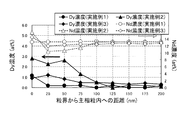
図4では、実施例1、実施例2および実施例3のSTEM−EDSによる2粒子粒界から主相粒子内の方向でのDyとNdの濃度定量値を示すが、粒界界面から主相粒子内にかけてのDy置換範囲がもっとも大きいのは、実施例2でおよそ100nmと確認され、Dy濃度ももっとも高く、添加化合物の添加量が多いことでDy置換範囲およびその濃度が大きくなっていることを示す。
実施例3のDy置換範囲は、およそ75nmであるが、Dy濃度は実施例2より小さい。これは、主相粒子内にあらかじめDyが存在することで、主相のDy置換が抑制されていることを示すと思われる。
FIG. 4 shows quantitative amounts of Dy and Nd in the direction from the two-particle grain boundary to the inside of the main phase particle by STEM-EDS in Example 1, Example 2, and Example 3. The largest Dy substitution range within the particles is confirmed to be about 100 nm in Example 2, the Dy concentration is also the highest, and the Dy substitution range and its concentration are increased by the addition amount of the added compound. Indicates.
The Dy substitution range of Example 3 is approximately 75 nm, but the Dy concentration is smaller than Example 2. This seems to indicate that Dy substitution in the main phase is suppressed by the presence of Dy in the main phase particles in advance.
比較例1、比較例2、比較例3および比較例4についても、STEM−EDSによる2粒子粒界から主相粒子内の方向でのDyとNdの濃度分布を調べたが、比較例1と比較例3ではDy置換範囲を明確に分けられるほど、Dyの明確な濃度差が確認できなかった。比較例2では、小さいがDy濃度差が確認されDy置換範囲を判断できたが、その幅は最大で1280nmと実施例に比べかなり広い。同様に比較例4でもDy置換範囲を判断できたが、その幅は最大で2120nmと実施例だけでなく、比較例2よりもさらに広いことが分かった。 For Comparative Example 1, Comparative Example 2, Comparative Example 3 and Comparative Example 4, the concentration distributions of Dy and Nd in the direction from the two-grain grain boundary to the main phase particle by STEM-EDS were examined. In Comparative Example 3, the clear concentration difference of Dy could not be confirmed as the Dy substitution range was clearly divided. In Comparative Example 2, although the Dy concentration difference was small but the Dy replacement range could be determined, the maximum width was 1280 nm, which is considerably wider than that of the example. Similarly, although the Dy substitution range could be determined in Comparative Example 4, it was found that the maximum width was 2120 nm, which was wider than that of Comparative Example 2.
図4において、実施例2と実施例3のDy置換範囲をシェル部最大幅ととり、そのシェル部最大幅の中でのxの最小値〜最大値を見積もると、実施例2では0.09〜0.40、実施例3では0.13〜0.18であった。
また、Ndの濃度分布が、シェル部に比べほぼ一定となっている範囲をコア部ととり、そのコア部の中でxの最小値〜最大値を見積もると、実施例2では0.00〜0.03、実施例3では0.05〜0.07であった。
In FIG. 4, the Dy replacement range of Example 2 and Example 3 is taken as the shell portion maximum width, and when the minimum value to the maximum value of x in the shell portion maximum width are estimated, 0.02 is obtained in Example 2. It was -0.40, and in Example 3, it was 0.13-0.18.
Further, when the core portion is a range where the Nd concentration distribution is substantially constant as compared with the shell portion, and the minimum value to the maximum value of x in the core portion are estimated, 0.00-2 in the second embodiment. In 0.03 and Example 3, it was 0.05-0.07.
比較例1、比較例2、比較例3および比較例4についても、実施例2と実施例3と同様に、シェル部とコア部のxの最小値〜最大値を見積もった。なお、比較例1と比較例3ではシェル部の判別が明確でなかったため、シェル部1000nmと仮定して、シェル部とコア部のxの最小値〜最大値を見積もった。
シェル部のxの最小値〜最大値は、比較例1が0.01〜0.02、比較例2が0.03〜0.05、比較例3が0.01〜0.02、比較例4が0.06〜0.11となった。またコア部のxの最小値〜最大値は、比較例1が0.01〜0.02、比較例2が0.01〜0.03、比較例3が0.00〜0.02、比較例4が0.04〜0.0.07となった。
For Comparative Example 1, Comparative Example 2, Comparative Example 3 and Comparative Example 4, as in Example 2 and Example 3, the minimum value to the maximum value of x in the shell portion and the core portion were estimated. In Comparative Example 1 and Comparative Example 3, since the shell part was not clearly determined, the minimum value and the maximum value of x of the shell part and the core part were estimated on the assumption that the shell part was 1000 nm.
The minimum value to the maximum value of x of the shell part are 0.01 to 0.02 in Comparative Example 1, 0.03 to 0.05 in Comparative Example 2, 0.01 to 0.02 in Comparative Example 3, and Comparative Example 4 became 0.06-0.11. Further, the minimum value to the maximum value of x in the core portion are 0.01 to 0.02 in Comparative Example 1, 0.01 to 0.03 in Comparative Example 2, 0.00 to 0.02 in Comparative Example 3, and comparison. Example 4 became 0.04-0.007.
実施例1については、粒界でDyが高濃度になっているが、STEM−EDSでは主相粒子内でのDy置換範囲を明確にするに至っていない。そのため、より高分解能で定量可能なアトムプローブ解析を実施した。他の実施例についてもSTEM−EDSにてDy置換範囲を明確にできなかった場合についてアトムプローブ解析を実施した。 As for Example 1, Dy has a high concentration at the grain boundary, but STEM-EDS has not yet clarified the Dy substitution range in the main phase particles. Therefore, an atom probe analysis that can be quantified with higher resolution was performed. As for other examples, atom probe analysis was performed for the case where the Dy substitution range could not be clearly defined by STEM-EDS.
図5では、実施例1のアトムプローブ解析による2粒子粒界近傍でのDyとNdの定量値を示すが、主相粒子と粒界相の界面でDy濃度が最大となり、Dy濃度が高いほどNdの濃度が低下していることから、主相粒子内でのDy置換範囲は最小で7nmであることが示されている。
Dy置換によりHcJが向上されるのは、Dyの高い異方性磁界によって逆磁区の核形成が抑制されるためであるとされるが、実施例1における7nmのDy置換範囲でも、その効果が大きく作用して高いHcJが得られている。
FIG. 5 shows the quantitative values of Dy and Nd in the vicinity of the two-particle grain boundary by the atom probe analysis of Example 1. The Dy concentration becomes maximum at the interface between the main phase particle and the grain boundary phase, and the higher the Dy concentration is. Since the Nd concentration is reduced, it is shown that the Dy substitution range in the main phase particles is 7 nm at the minimum.
The reason why HcJ is improved by Dy substitution is that nucleation of reverse magnetic domains is suppressed by an anisotropic magnetic field having high Dy, but the effect is also achieved in the Dy substitution range of 7 nm in Example 1. High HcJ is obtained by acting greatly.
実施例1について、アトムプローブ解析で確認されたDy置換範囲をシェル部最大幅ととり、そのシェル部最大幅の中でのxの最小値〜最大値を見積もると、実施例2では0.02〜0.08であった。また、Ndの濃度分布が、シェル部に比べほぼ一定となっている範囲をコア部ととり、そのコア部の中でxの最小値〜最大値を見積もると、実施例1では0.00〜0.01であった。 Regarding Example 1, when the Dy replacement range confirmed by the atom probe analysis is taken as the maximum shell part width, and the minimum value to the maximum value of x in the maximum shell part width are estimated, 0.02 is obtained in Example 2. -0.08. In addition, when the range in which the Nd concentration distribution is substantially constant as compared with the shell portion is taken as the core portion, and the minimum value to the maximum value of x are estimated in the core portion, in Example 1, 0.00 to 0.01.
実施例5および6では、微粉砕粉の粒径をそれぞれ約2μm、約3μmとして実施例4よりも微粉砕粉を微細化しており、そこへ実施例4と同様にDyを含有する合金を添加している。実施例5および6では微細焼結組織での主相粒子径もほぼそれに近い状態となっており、主相粒子のシェル部最大厚みもほぼ同じ厚みとなっている。そのため、より微細な実施例5では主相粒子のコア部体積割合がより小さくなっており、磁気特性としてはBrが低くなっているが、HcJが大きく向上しており発明の効果が現われている。
一方、比較例5および比較例6は、実施例5および実施例6で添加したDyを含有する合金の微粉砕粉にc−BNコーティングを施していないため、焼結過程において主相粒子中にDyが多量に取り込まれて厚いシェル部が形成されており、原料合金のみより作製した場合よりBrが大きく低下しているが、HcJが実施例5および実施例6ほど大きくは向上していない。
しかしながら、実施例5において、磁気特性としては大きな問題ではないが、原料合金のみの場合に対しBrの低下がやや大きくなっており、Brも十分に高く維持しながらHcJを向上させる上では主相粒子のコア部体積割合を90%以上とすることが好ましい。
In Examples 5 and 6, the particle size of the finely pulverized powder is about 2 μm and about 3 μm, respectively, and the finely pulverized powder is made finer than in Example 4, and an alloy containing Dy is added thereto as in Example 4. doing. In Examples 5 and 6, the main phase particle diameter in the fine sintered structure is almost similar to that, and the maximum thickness of the shell portion of the main phase particles is almost the same. Therefore, in the finer example 5, the core portion volume ratio of the main phase particles is smaller, and Br is low as the magnetic properties, but HcJ is greatly improved, and the effect of the invention appears. .
On the other hand, in Comparative Example 5 and Comparative Example 6, since c-BN coating was not applied to the finely pulverized powder of the alloy containing Dy added in Example 5 and Example 6, it was included in the main phase particles in the sintering process. A large amount of Dy is taken in to form a thick shell portion, and Br is greatly reduced as compared with the case where the material is made of only the raw material alloy, but HcJ is not improved as much as Example 5 and Example 6.
However, in Example 5, although it is not a big problem as a magnetic characteristic, the fall of Br is a little large compared with the case of only a raw material alloy, and in order to improve HcJ while maintaining Br high enough, it is a main phase. The core volume ratio of the particles is preferably 90% or more.
実施例7では、B含有量が0.72と少なくなっておりHcJも892kA/mと小さいが、これは原料合金のみで作製した場合のHcJが413kA/mときわめて小さいことによるもので、Dyを含む合金の添加によって479kA/mの向上がなされており、本発明による効果は得られている。
しかしながら、製品として適するHcJを得る上では原料合金のみによるもともとのHcJもある程度必要であるといえ、実施例7のようにB含有量を少なくし過ぎることはFeを含む軟磁性相を形成してHcJが低くなることにつながるため、B含有量は0.75mass%以上とすることが好ましい。
In Example 7, the B content was reduced to 0.72, and the HcJ was as small as 892 kA / m. This is because the HcJ when made of only the raw material alloy was as small as 413 kA / m. The addition of an alloy containing is improved by 479 kA / m, and the effect of the present invention is obtained.
However, in order to obtain HcJ suitable as a product, it can be said that the original HcJ based only on the raw material alloy is also necessary to some extent, and reducing the B content too much as in Example 7 forms a soft magnetic phase containing Fe. Since it leads to HcJ becoming low, it is preferable that B content shall be 0.75 mass% or more.
実施例8では実施例1の原料合金のNdの全て、実施例9ではNdの一部をPrで置換した原料合金をそれぞれ使用して試料を作製しているが、Ndのみを使用している実施例1と同様に本発明による効果が得られている。 In Example 8, the sample was prepared using all the Nd of the raw material alloy of Example 1, and in Example 9, the raw material alloy in which a part of Nd was replaced with Pr was used, but only Nd was used. The effect by this invention is acquired similarly to Example 1. FIG.
実施例10では、実施例1で使用したDyを含有する合金のDyを全て、実施例11では半分をTbで置換した合金をそれぞれ使用して試料を作製しているが、Dyのみ含有した合金の添加よりもHcJが大きく向上している。これは、Tbで主相を構成するNdなどLRを置換した場合は、HcJに大きく影響する異方性磁界がDyで置換した場合より大きくなることによる。 In Example 10, samples were prepared using all of Dy of the alloy containing Dy used in Example 1, and in Example 11, an alloy in which half was substituted with Tb. HcJ is greatly improved over the addition of. This is because, when LR such as Nd constituting the main phase is replaced with Tb, the anisotropic magnetic field that greatly affects HcJ is larger than when it is replaced with Dy.
表4に実施例1、実施例7、実施例12における2粒子粒界におけるR量(Nd+Dy)、T量(Fe+Co)、Cu、Alの含有比率を示す。実施例12では、実施例1で使用したDyを含有する合金のDyの一部をAlに置換した合金を使用して試料を作製しているが、実施例1よりも大きくHcJが向上している。アトムプローブ解析から実施例12の2粒子粒界の粒界相において、NdとDyを合わせたR量が20.36at%、FeとCoを合わせたT量が73.51at%、Cuが0.93at%、Alが0.12at%であった。一方で、Dyを含有する合金にAlを含ませていない実施例1では、NdとDyを合わせた希土類が17.87at%、FeとCoを合わせたT量が77.15at%、Cuが0.71at%、Alが0.05at%であった。このことから、実施例12において実施例1よりもにHcJ向上が大きくなったのは、HcJ向上に効果のあるAlが加えられ2粒子粒界に存在したことによると考えられる。
また、実施例7について2粒子粒界のアトムプローブ解析を行ったところ、NdとDyを合わせたR量が7.39at%、FeとCoを合わせたT量が91.01at%、Cuが0.80at%、Alが0.02at%で、R量が少なくなり、T量が多く存在している。このことから、実施例7ではB含有量を過剰に少なくしているため主相を組まないFeやCoの余剰ができて粒界相においてRと軟磁性相を形成してしまい、もともとのHcJが小さい結果となっていると考えられる。ただ、実施例7においても本発明によるHcJ向上の効果は現れている。
したがって、製品として適するHcJを得る上で、焼結体の2粒子粒界においてR(RはY(イットリウム)および希土類元素の1種又は2種以上)が10〜30at%であり、T(Fe又はFe及びCoを必須とする1種又は2種以上の遷移金属)が65〜85at%であって、Cuが0.70〜4.0at%、Alが0.07〜2.0at%、であることが好ましい。
Table 4 shows the content ratios of R amount (Nd + Dy), T amount (Fe + Co), Cu, and Al at the grain boundary of Example 1, Example 7, and Example 12. In Example 12, a sample was prepared using an alloy in which a part of Dy of the alloy containing Dy used in Example 1 was replaced with Al. However, HcJ was greatly improved as compared with Example 1. Yes. From the atom probe analysis, in the grain boundary phase of the two-grain grain boundary of Example 12, the R amount combining Nd and Dy is 20.36 at%, the T amount combining Fe and Co is 73.51 at%, and Cu is 0.00. 93 at% and Al were 0.12 at%. On the other hand, in Example 1 in which Al was not included in the alloy containing Dy, the rare earth combined with Nd and Dy was 17.87 at%, the T amount combined with Fe and Co was 77.15 at%, and Cu was 0. .71 at% and Al was 0.05 at%. From this, it can be considered that the improvement in HcJ in Example 12 was greater than that in Example 1 because Al that was effective in improving HcJ was added and existed at the grain boundary.
Further, when an atom probe analysis of the two-grain grain boundary was performed on Example 7, the R amount combining Nd and Dy was 7.39 at%, the T amount combining Fe and Co was 91.01 at%, and Cu was 0 .80 at%, Al is 0.02 at%, the R amount is small, and the T amount is large. From this, in Example 7, the B content was excessively reduced, so that an excess of Fe or Co not forming the main phase was formed, and R and a soft magnetic phase were formed in the grain boundary phase, and the original HcJ Is considered to be a small result. However, also in Example 7, the effect of improving HcJ by the present invention appears.
Therefore, in obtaining HcJ suitable as a product, R (where R is one or more of Y (yttrium) and rare earth elements) is 10 to 30 at% at the two-grain boundary of the sintered body, and T (Fe Or one or more transition metals essentially including Fe and Co) is 65 to 85 at%, Cu is 0.70 to 4.0 at%, and Al is 0.07 to 2.0 at%. Preferably there is.
参考例7は、比較例3および4によりも多量のCo、Cu、Alを原料合金から加えており、Co、Cu、Alを含まない以外は組成と組織がほぼ同じである参考例1と比べHcJが高い。しかし、参考例7へ表1のGの組成の合金を添加した実施例13では、他の実施例と同様にBr低下を抑えつつHcJを向上できているものの、参考例1に表1のGの組成の合金を添加した実施例1ほど大きなHcJの向上が得られていない。実施例13でHcJの向上がやや小さい原因は確定できていない。しかし、Co、Alは主相に固溶しTのFeを置換できるので、混合添加して加えたHRの主相LRとの置換し易さに影響を及ぼすことは否定できない。また、Cuは主相に固溶することはほとんどないものの、存在量が多い場合は主相のLR、主にNdとも反応して主相を壊していくため、粒界に濃縮されて過剰に存在したCuにより結晶粒径の小さな主相粒子が壊されて高HcJな主相粒子が少なくなったとも予想される。
いずれにせよ、多量のCo、Cu、AlによるHcJの向上を完全に残しながらDyによるHcJのさらなる向上を実現するのは難しい。しかし、DyによるHcJの向上は原料合金からDyを単純に含有させるよりもずっと大きな効果が得られており、十分に実用可能な手法である。このことから、Co、Cu、Alの含有量の上限については、Coが1.10mass%、Cuが0.18mass%、Alが0.40mass%である。
Reference Example 7 has a larger amount of Co, Cu, and Al added from the raw material alloy than Comparative Examples 3 and 4, and the composition and structure are substantially the same except that Co, Cu, and Al are not included. HcJ is high. However, in Example 13 in which an alloy having the composition of G in Table 1 was added to Reference Example 7, HcJ was improved while suppressing a decrease in Br as in the other Examples, but G in Table 1 was added to Reference Example 1. The improvement of HcJ as great as that of Example 1 to which an alloy having the composition was added was not obtained. The reason why the improvement in HcJ is slightly small in Example 13 cannot be determined. However, since Co and Al can be dissolved in the main phase to replace the Fe of T, it cannot be denied that the replacement of the added HR with the main phase LR of HR is affected. In addition, Cu hardly dissolves in the main phase, but when the abundance is large, it reacts with the main phase LR, mainly Nd, and destroys the main phase, so it is concentrated at the grain boundary and excessive. It is also expected that the main phase particles having a small crystal grain size were broken by the existing Cu and the main phase particles having a high HcJ were reduced.
In any case, it is difficult to achieve further improvement of HcJ by Dy while completely leaving improvement of HcJ by a large amount of Co, Cu, and Al. However, the improvement of HcJ by Dy is much more effective than simply including Dy from the raw material alloy, and is a sufficiently practical technique. From this, the upper limit of the contents of Co, Cu, and Al is 1.10 mass% for Co, 0.18 mass% for Cu, and 0.40 mass% for Al.
本発明により、少ないDy含有量でHcJを顕著に向上させたR−T−B系焼結磁石を得ることができ、さらに、従来の磁気特性を維持する場合は、Dy含有量を大幅に削減したR−T−B系焼結磁石を得ることができる。 According to the present invention, it is possible to obtain an RTB-based sintered magnet having a significantly improved HcJ with a small Dy content, and further, when maintaining conventional magnetic properties, the Dy content is greatly reduced. R-T-B based sintered magnet can be obtained.
以上のように、本発明は、高い磁気特性を維持しつつ、重希土類元素の使用量を削減したR−T−B系焼結磁石を提供することができる。 As described above, the present invention can provide an RTB-based sintered magnet in which the amount of heavy rare earth elements used is reduced while maintaining high magnetic properties.
1 主相粒子
2 コア部
3 シェル部
4 シェル部の最大厚み
1
Claims (4)
Priority Applications (5)
| Application Number | Priority Date | Filing Date | Title |
|---|---|---|---|
| JP2012212333A JP6089535B2 (en) | 2011-10-28 | 2012-09-26 | R-T-B sintered magnet |
| PCT/JP2012/075740 WO2013061744A1 (en) | 2011-10-28 | 2012-10-04 | R-t-b sintered magnet |
| CN201280053073.6A CN103890868B (en) | 2011-10-28 | 2012-10-04 | R-t-b sintered magnet |
| US14/354,865 US9548148B2 (en) | 2011-10-28 | 2012-10-04 | R-T-B based sintered magnet |
| DE112012004502.5T DE112012004502T5 (en) | 2011-10-28 | 2012-10-04 | R-T-B based sintered magnet |
Applications Claiming Priority (3)
| Application Number | Priority Date | Filing Date | Title |
|---|---|---|---|
| JP2011236617 | 2011-10-28 | ||
| JP2011236617 | 2011-10-28 | ||
| JP2012212333A JP6089535B2 (en) | 2011-10-28 | 2012-09-26 | R-T-B sintered magnet |
Publications (2)
| Publication Number | Publication Date |
|---|---|
| JP2013110387A JP2013110387A (en) | 2013-06-06 |
| JP6089535B2 true JP6089535B2 (en) | 2017-03-08 |
Family
ID=48167579
Family Applications (1)
| Application Number | Title | Priority Date | Filing Date |
|---|---|---|---|
| JP2012212333A Active JP6089535B2 (en) | 2011-10-28 | 2012-09-26 | R-T-B sintered magnet |
Country Status (5)
| Country | Link |
|---|---|
| US (1) | US9548148B2 (en) |
| JP (1) | JP6089535B2 (en) |
| CN (1) | CN103890868B (en) |
| DE (1) | DE112012004502T5 (en) |
| WO (1) | WO2013061744A1 (en) |
Families Citing this family (34)
| Publication number | Priority date | Publication date | Assignee | Title |
|---|---|---|---|---|
| JP5790617B2 (en) | 2012-10-18 | 2015-10-07 | トヨタ自動車株式会社 | Rare earth magnet manufacturing method |
| JP5464289B1 (en) * | 2013-04-22 | 2014-04-09 | Tdk株式会社 | R-T-B sintered magnet |
| US10468165B2 (en) | 2013-06-05 | 2019-11-05 | Toyota Jidosha Kabushiki Kaisha | Rare-earth magnet and method for manufacturing same |
| EP3011573B1 (en) * | 2013-06-17 | 2020-06-10 | Urban Mining Technology Company, LLC | Magnet recycling to create nd-fe-b magnets with improved or restored magnetic performance |
| KR102215818B1 (en) * | 2013-09-24 | 2021-02-17 | 엘지전자 주식회사 | Hot-deformed magnet comprising nonmagnetic alloys and fabricating method thereof |
| CN104674115A (en) | 2013-11-27 | 2015-06-03 | 厦门钨业股份有限公司 | Low-B rare earth magnet |
| JP6142793B2 (en) * | 2013-12-20 | 2017-06-07 | Tdk株式会社 | Rare earth magnets |
| JP6142792B2 (en) * | 2013-12-20 | 2017-06-07 | Tdk株式会社 | Rare earth magnets |
| JP6142794B2 (en) * | 2013-12-20 | 2017-06-07 | Tdk株式会社 | Rare earth magnets |
| CN105900216B (en) * | 2014-02-07 | 2019-05-10 | 株式会社神户制钢所 | Flat-panel monitor wiring film |
| JP6003920B2 (en) | 2014-02-12 | 2016-10-05 | トヨタ自動車株式会社 | Rare earth magnet manufacturing method |
| CN104952574A (en) | 2014-03-31 | 2015-09-30 | 厦门钨业股份有限公司 | Nd-Fe-B-Cu type sintered magnet containing W |
| JP6269279B2 (en) * | 2014-04-15 | 2018-01-31 | Tdk株式会社 | Permanent magnet and motor |
| CN105321699B (en) * | 2014-07-07 | 2017-11-24 | 厦门钨业股份有限公司 | A kind of manufacture method and its magnet of Nd-Fe-B series sintered magnet |
| JP6511779B2 (en) * | 2014-11-12 | 2019-05-15 | Tdk株式会社 | RTB based sintered magnet |
| CN107077935A (en) | 2014-12-08 | 2017-08-18 | Lg电子株式会社 | The magnet and its manufacture method of hot compression deformation comprising nonmagnetic alloy |
| JP6504044B2 (en) * | 2015-02-16 | 2019-04-24 | Tdk株式会社 | Rare earth permanent magnet |
| JP6424664B2 (en) * | 2015-02-16 | 2018-11-21 | Tdk株式会社 | Rare earth permanent magnet |
| JP6468435B2 (en) * | 2015-04-15 | 2019-02-13 | Tdk株式会社 | R-T-B sintered magnet |
| JP2017098537A (en) * | 2015-11-13 | 2017-06-01 | Tdk株式会社 | R-T-B based sintered magnet |
| JP6645219B2 (en) * | 2016-02-01 | 2020-02-14 | Tdk株式会社 | Alloy for RTB based sintered magnet, and RTB based sintered magnet |
| JP6848736B2 (en) | 2016-07-15 | 2021-03-24 | Tdk株式会社 | RTB series rare earth permanent magnet |
| JP6848735B2 (en) * | 2016-07-15 | 2021-03-24 | Tdk株式会社 | RTB series rare earth permanent magnet |
| US10748685B2 (en) * | 2017-03-30 | 2020-08-18 | Tdk Corporation | R-T-B based sintered magnet |
| CN108735413A (en) * | 2018-05-18 | 2018-11-02 | 宁波科田磁业有限公司 | One kind high-coercivity magnet of high-performance containing Tb and preparation method thereof |
| CN110619984B (en) | 2018-06-19 | 2021-12-07 | 厦门钨业股份有限公司 | R-Fe-B sintered magnet with low B content and preparation method thereof |
| CN110047636B (en) * | 2019-04-17 | 2021-09-10 | 南京理工大学 | Preparation method of high-coercivity La/Ce-rich sintered magnet |
| CN111223625B (en) * | 2020-02-26 | 2022-08-16 | 福建省长汀金龙稀土有限公司 | Neodymium-iron-boron magnet material, raw material composition, preparation method and application |
| CN111223628B (en) * | 2020-02-26 | 2022-02-01 | 厦门钨业股份有限公司 | Neodymium-iron-boron magnet material, raw material composition, preparation method and application |
| CN111243807B (en) * | 2020-02-26 | 2021-08-27 | 厦门钨业股份有限公司 | Neodymium-iron-boron magnet material, raw material composition, preparation method and application |
| CN111223627B (en) * | 2020-02-26 | 2021-12-17 | 厦门钨业股份有限公司 | Neodymium-iron-boron magnet material, raw material composition, preparation method and application |
| JP7303157B2 (en) * | 2020-06-01 | 2023-07-04 | トヨタ自動車株式会社 | Rare earth magnet and manufacturing method thereof |
| CN113838620B (en) * | 2020-06-23 | 2023-03-14 | 比亚迪股份有限公司 | Rare earth permanent magnetic material and preparation method thereof |
| CN114203380A (en) * | 2021-12-17 | 2022-03-18 | 沈阳中北通磁科技股份有限公司 | High-performance rare earth permanent magnet |
Family Cites Families (14)
| Publication number | Priority date | Publication date | Assignee | Title |
|---|---|---|---|---|
| JP2510806B2 (en) | 1992-03-10 | 1996-06-26 | ミサワホーム株式会社 | Positioning structure of work stopper in sizer |
| JPH07122413A (en) | 1993-10-28 | 1995-05-12 | Hitachi Metals Ltd | Rare earth permanent magnet and manufacture thereof |
| US7618497B2 (en) * | 2003-06-30 | 2009-11-17 | Tdk Corporation | R-T-B based rare earth permanent magnet and method for production thereof |
| US8123832B2 (en) | 2005-03-14 | 2012-02-28 | Tdk Corporation | R-T-B system sintered magnet |
| JP4900085B2 (en) * | 2007-06-29 | 2012-03-21 | Tdk株式会社 | Rare earth magnet manufacturing method |
| WO2009016815A1 (en) * | 2007-07-27 | 2009-02-05 | Hitachi Metals, Ltd. | R-Fe-B RARE EARTH SINTERED MAGNET |
| WO2010082492A1 (en) * | 2009-01-16 | 2010-07-22 | 日立金属株式会社 | Method for producing r-t-b sintered magnet |
| EP2455954B1 (en) | 2009-07-15 | 2019-10-16 | Hitachi Metals, Ltd. | Process for production of r-t-b based sintered magnets |
| WO2011108704A1 (en) * | 2010-03-04 | 2011-09-09 | Tdk株式会社 | Sintered rare-earth magnet and motor |
| JP2011211056A (en) * | 2010-03-30 | 2011-10-20 | Tdk Corp | Rare earth sintered magnet, motor, and automobile |
| WO2011122667A1 (en) * | 2010-03-30 | 2011-10-06 | Tdk株式会社 | Rare earth sintered magnet, method for producing the same, motor, and automobile |
| JP2011211071A (en) * | 2010-03-30 | 2011-10-20 | Tdk Corp | Sintered magnet, motor, automobile, and method for producing the sintered magnet |
| US9548157B2 (en) * | 2010-03-30 | 2017-01-17 | Tdk Corporation | Sintered magnet, motor, automobile, and method for producing sintered magnet |
| JP5429002B2 (en) * | 2010-03-30 | 2014-02-26 | Tdk株式会社 | Sintered magnet, motor and automobile |
-
2012
- 2012-09-26 JP JP2012212333A patent/JP6089535B2/en active Active
- 2012-10-04 CN CN201280053073.6A patent/CN103890868B/en active Active
- 2012-10-04 WO PCT/JP2012/075740 patent/WO2013061744A1/en active Application Filing
- 2012-10-04 DE DE112012004502.5T patent/DE112012004502T5/en active Pending
- 2012-10-04 US US14/354,865 patent/US9548148B2/en active Active
Also Published As
| Publication number | Publication date |
|---|---|
| CN103890868B (en) | 2017-05-03 |
| US20140283649A1 (en) | 2014-09-25 |
| WO2013061744A1 (en) | 2013-05-02 |
| DE112012004502T5 (en) | 2014-12-18 |
| CN103890868A (en) | 2014-06-25 |
| JP2013110387A (en) | 2013-06-06 |
| US9548148B2 (en) | 2017-01-17 |
Similar Documents
| Publication | Publication Date | Title |
|---|---|---|
| JP6089535B2 (en) | R-T-B sintered magnet | |
| CN107871582B (en) | R-Fe-B sintered magnet | |
| CN106024253B (en) | R-Fe-B sintered magnet and preparation method thereof | |
| US10573438B2 (en) | R-(Fe, Co)-B sintered magnet and making method | |
| US10410775B2 (en) | R—Fe—B sintered magnet and making method | |
| CN107871581B (en) | Method for preparing R-Fe-B sintered magnet | |
| TWI413136B (en) | Rare earth permanent magnet | |
| JP5477282B2 (en) | R-T-B system sintered magnet and manufacturing method thereof | |
| JP3891307B2 (en) | Nd-Fe-B rare earth permanent sintered magnet material | |
| EP2388350B1 (en) | Method for producing r-t-b sintered magnet | |
| JP5856953B2 (en) | Rare earth permanent magnet manufacturing method and rare earth permanent magnet | |
| JP7418598B2 (en) | Heavy rare earth alloys, neodymium iron boron permanent magnet materials, raw materials and manufacturing methods | |
| JPH0521218A (en) | Production of rare-earth permanent magnet | |
| WO2005015580A1 (en) | R-t-b sintered magnet and rare earth alloy | |
| JP4543940B2 (en) | Method for producing RTB-based sintered magnet | |
| JP2014216338A (en) | R-T-B sintered magnet | |
| JP4900085B2 (en) | Rare earth magnet manufacturing method | |
| JP4821128B2 (en) | R-Fe-B rare earth permanent magnet | |
| JP4895027B2 (en) | R-T-B sintered magnet and method for producing R-T-B sintered magnet | |
| JP4702522B2 (en) | R-T-B system sintered magnet and manufacturing method thereof | |
| JP4955217B2 (en) | Raw material alloy for RTB-based sintered magnet and method for manufacturing RTB-based sintered magnet | |
| JP2018174311A (en) | Method for manufacturing r-t-b based sintered magnet | |
| JP4556727B2 (en) | Manufacturing method of rare earth sintered magnet | |
| JP4076080B2 (en) | Rare earth permanent magnet manufacturing method | |
| JP2005286174A (en) | R-t-b-based sintered magnet |
Legal Events
| Date | Code | Title | Description |
|---|---|---|---|
| A621 | Written request for application examination |
Free format text: JAPANESE INTERMEDIATE CODE: A621 Effective date: 20150508 |
|
| A131 | Notification of reasons for refusal |
Free format text: JAPANESE INTERMEDIATE CODE: A131 Effective date: 20160405 |
|
| A601 | Written request for extension of time |
Free format text: JAPANESE INTERMEDIATE CODE: A601 Effective date: 20160530 |
|
| RD02 | Notification of acceptance of power of attorney |
Free format text: JAPANESE INTERMEDIATE CODE: A7422 Effective date: 20160701 |
|
| A521 | Request for written amendment filed |
Free format text: JAPANESE INTERMEDIATE CODE: A523 Effective date: 20160725 |
|
| TRDD | Decision of grant or rejection written | ||
| A01 | Written decision to grant a patent or to grant a registration (utility model) |
Free format text: JAPANESE INTERMEDIATE CODE: A01 Effective date: 20170110 |
|
| A61 | First payment of annual fees (during grant procedure) |
Free format text: JAPANESE INTERMEDIATE CODE: A61 Effective date: 20170123 |
|
| R150 | Certificate of patent or registration of utility model |
Ref document number: 6089535 Country of ref document: JP Free format text: JAPANESE INTERMEDIATE CODE: R150 |