JP2005291457A - 玉軸受ユニット - Google Patents
玉軸受ユニット Download PDFInfo
- Publication number
- JP2005291457A JP2005291457A JP2004110889A JP2004110889A JP2005291457A JP 2005291457 A JP2005291457 A JP 2005291457A JP 2004110889 A JP2004110889 A JP 2004110889A JP 2004110889 A JP2004110889 A JP 2004110889A JP 2005291457 A JP2005291457 A JP 2005291457A
- Authority
- JP
- Japan
- Prior art keywords
- revolution speed
- outer ring
- balls
- load
- bearing unit
- Prior art date
- Legal status (The legal status is an assumption and is not a legal conclusion. Google has not performed a legal analysis and makes no representation as to the accuracy of the status listed.)
- Pending
Links
Images


Classifications
-
- F—MECHANICAL ENGINEERING; LIGHTING; HEATING; WEAPONS; BLASTING
- F16—ENGINEERING ELEMENTS AND UNITS; GENERAL MEASURES FOR PRODUCING AND MAINTAINING EFFECTIVE FUNCTIONING OF MACHINES OR INSTALLATIONS; THERMAL INSULATION IN GENERAL
- F16C—SHAFTS; FLEXIBLE SHAFTS; ELEMENTS OR CRANKSHAFT MECHANISMS; ROTARY BODIES OTHER THAN GEARING ELEMENTS; BEARINGS
- F16C41/00—Other accessories, e.g. devices integrated in the bearing not relating to the bearing function as such
- F16C41/007—Encoders, e.g. parts with a plurality of alternating magnetic poles
-
- F—MECHANICAL ENGINEERING; LIGHTING; HEATING; WEAPONS; BLASTING
- F16—ENGINEERING ELEMENTS AND UNITS; GENERAL MEASURES FOR PRODUCING AND MAINTAINING EFFECTIVE FUNCTIONING OF MACHINES OR INSTALLATIONS; THERMAL INSULATION IN GENERAL
- F16C—SHAFTS; FLEXIBLE SHAFTS; ELEMENTS OR CRANKSHAFT MECHANISMS; ROTARY BODIES OTHER THAN GEARING ELEMENTS; BEARINGS
- F16C19/00—Bearings with rolling contact, for exclusively rotary movement
- F16C19/02—Bearings with rolling contact, for exclusively rotary movement with bearing balls essentially of the same size in one or more circular rows
- F16C19/14—Bearings with rolling contact, for exclusively rotary movement with bearing balls essentially of the same size in one or more circular rows for both radial and axial load
- F16C19/18—Bearings with rolling contact, for exclusively rotary movement with bearing balls essentially of the same size in one or more circular rows for both radial and axial load with two or more rows of balls
- F16C19/181—Bearings with rolling contact, for exclusively rotary movement with bearing balls essentially of the same size in one or more circular rows for both radial and axial load with two or more rows of balls with angular contact
- F16C19/183—Bearings with rolling contact, for exclusively rotary movement with bearing balls essentially of the same size in one or more circular rows for both radial and axial load with two or more rows of balls with angular contact with two rows at opposite angles
- F16C19/184—Bearings with rolling contact, for exclusively rotary movement with bearing balls essentially of the same size in one or more circular rows for both radial and axial load with two or more rows of balls with angular contact with two rows at opposite angles in O-arrangement
- F16C19/186—Bearings with rolling contact, for exclusively rotary movement with bearing balls essentially of the same size in one or more circular rows for both radial and axial load with two or more rows of balls with angular contact with two rows at opposite angles in O-arrangement with three raceways provided integrally on parts other than race rings, e.g. third generation hubs
-
- F—MECHANICAL ENGINEERING; LIGHTING; HEATING; WEAPONS; BLASTING
- F16—ENGINEERING ELEMENTS AND UNITS; GENERAL MEASURES FOR PRODUCING AND MAINTAINING EFFECTIVE FUNCTIONING OF MACHINES OR INSTALLATIONS; THERMAL INSULATION IN GENERAL
- F16C—SHAFTS; FLEXIBLE SHAFTS; ELEMENTS OR CRANKSHAFT MECHANISMS; ROTARY BODIES OTHER THAN GEARING ELEMENTS; BEARINGS
- F16C19/00—Bearings with rolling contact, for exclusively rotary movement
- F16C19/52—Bearings with rolling contact, for exclusively rotary movement with devices affected by abnormal or undesired conditions
- F16C19/522—Bearings with rolling contact, for exclusively rotary movement with devices affected by abnormal or undesired conditions related to load on the bearing, e.g. bearings with load sensors or means to protect the bearing against overload
-
- F—MECHANICAL ENGINEERING; LIGHTING; HEATING; WEAPONS; BLASTING
- F16—ENGINEERING ELEMENTS AND UNITS; GENERAL MEASURES FOR PRODUCING AND MAINTAINING EFFECTIVE FUNCTIONING OF MACHINES OR INSTALLATIONS; THERMAL INSULATION IN GENERAL
- F16C—SHAFTS; FLEXIBLE SHAFTS; ELEMENTS OR CRANKSHAFT MECHANISMS; ROTARY BODIES OTHER THAN GEARING ELEMENTS; BEARINGS
- F16C2326/00—Articles relating to transporting
- F16C2326/01—Parts of vehicles in general
- F16C2326/02—Wheel hubs or castors
Landscapes
- Engineering & Computer Science (AREA)
- General Engineering & Computer Science (AREA)
- Mechanical Engineering (AREA)
- Rolling Contact Bearings (AREA)
- Force Measurement Appropriate To Specific Purposes (AREA)
Abstract
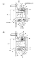
【解決手段】 各公転速度検出用センサ6a、6bにより、上記各玉8a、8bの公転速度を検出する。そして、この公転速度により、外輪1とハブ11aとの間に加わる荷重を求める。上記各玉8a、8bの直径dとピッチ円直径Dとの比d/Dを0.12〜0.4の範囲に規制し、荷重変動に伴う公転速度変動を大きくする事で、上記課題を解決する。
【選択図】 図1
Description
nc ={1−(d・cosα/D)・(ni /2)}+{1+(d・cosα/D)・(no /2)} −−− (1)
このうちの外輪相当部材は、内周面に外輪軌道を有する。
又、上記内輪相当部材は、上記外輪相当部材の内径側にこの外輪相当部材と同心に配置されたもので、外周面に内輪軌道を有する。
又、上記各玉は、この内輪軌道と上記外輪軌道との間に、接触角を付与された状態で設けられている。
又、上記公転速度検出用センサは、上記各玉の公転速度を検出するものである。
更に、本発明の玉軸受ユニットは、これら各玉の直径とこれら各玉のピッチ円直径との比を、0.12〜0.4の範囲に規制している。
特に、本発明の玉軸受ユニットの場合には、各玉の直径と各玉のピッチ円直径との比を0.12〜0.4の範囲に規制した事に伴い、荷重の変動に基づく各玉の公転速度の変化を大きくできる。この為、この荷重の測定精度を十分に確保できる。
そして、請求項2に記載した発明の場合には、上記両列の玉の公転速度を検出する為に、1対の公転速度検出用センサを設ける。
この様な構造を採用すれば、上記外輪相当部材と上記内輪相当部材との間に加わるラジアル荷重及びアキシアル荷重を正確に求められる。
そして、好ましくは、請求項5に記載した様に、上記外輪相当部材と上記内輪相当部材とのうちで使用時に回転する部材である回転輪に車輪を支持固定し、同じく使用時にも回転しない部材である静止輪を懸架装置に支持固定する。
この様に構成すれば、車輪と懸架装置との間に加わる荷重を求めて、ABS、TCS、VSC等の車両用走行安定化装置の制御を適切に行なえる。
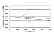
先ず、本発明をABS、TCS、VSC等の車両用走行安定化装置の制御に利用する事を考慮した場合、車両の走行状態を安定させる為には、上記アキシアル荷重Fyを検出する分解能は、1000N程度、好ましくは500N程度に抑える必要がある。分解能がこれよりも悪い(1000Nよりも大きな分解能でしか測定できない)と、走行安定性確保の為の制御に上記アキシアル荷重Fyを利用する意味がなくなる。又、この制御にこのアキシアル荷重Fyを利用する場合、このアキシアル荷重Fyの測定範囲に関しては、−1000N〜6000N程度(フルスケールを7000N程度)は必要である。
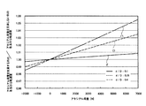
尚、前記図1に示した2例の玉軸受ユニットのうち、(A)に示した構造は、上記比d/Dが0.15であり、7000Nなるフルスケールの範囲での、上記各列の玉8a、8bの公転速度nc 同士の比の変化は2ポイント、分解能700Nである。
又、(B)に示した構造は、上記比d/Dが0.25であり、7000Nなるフルスケールの範囲での、上記各列の玉8a、8bの公転速度nc 同士の比の変化は3.5ポイント、分解能400Nである。
又、上記各玉8a、8bに付与している予圧を変える事によっても、リニアリティ(直線性)やゲイン特性を変える事ができる。この場合に上記予圧は、980N〜9800N(100kgf 〜1000kgf )の範囲で変更可能である。
尚、上述の様な、上記アキシアル荷重Fyの変動に伴って上記各玉8a、8bの公転速度nc が変化する程度を変える方法は、それぞれ単独で採用しても、組み合わせて採用しても良い。
又、本発明を実施する場合、図示の様に、両列の玉8a、8bに関して直径dとピッチ円直径Dとの比d/Dを大きくするだけでなく、片側の列の比d/Dのみを大きくする事もできる。又、複列玉軸受ユニットに限らず、単列の玉軸受ユニットにも適用できる。
2 外輪軌道
3 取付孔
4、4a センサユニット
5、5a 先端部
6a、6b 公転速度検出用センサ
7、7a 回転速度検出用センサ
8a、8b 玉
9a、9b 保持器
10a、10b 公転速度検出用エンコーダ
11、11a ハブ
12、12a 回転速度検出用エンコーダ
13 内輪軌道
14 カバー
15 スプライン孔
Claims (5)
- 内周面に外輪軌道を有する外輪相当部材と、この外輪相当部材の内径側にこの外輪相当部材と同心に配置された、外周面に内輪軌道を有する内輪相当部材と、この内輪軌道と上記外輪軌道との間に接触角を付与された状態で設けられた複数個の玉と、これら各玉の公転速度を検出する公転速度検出用センサとを備え、これら各玉の直径とこれら各玉のピッチ円直径との比を0.12〜0.4の範囲に規制した玉軸受ユニット。
- 外輪相当部材の内周面に設けられた複列の外輪軌道と、内輪相当部材の外周面に設けられた複列の内輪軌道との間に、両列毎に複数個ずつの玉が、両列同士の間で接触角の方向を互いに逆にして設けられており、これら両列の玉の公転速度を検出する為に、1対の公転速度検出用センサが設けられている、請求項1に記載した玉軸受ユニット。
- 外輪相当部材の内周面に設けられた複列の外輪軌道と、内輪相当部材の外周面に設けられた複列の内輪軌道との間に、両列毎に複数個ずつの玉が、両列同士の間で接触角の方向を互いに逆にして設けられており、これら両列の玉の公転速度の差を検出する為に、単一の公転速度検出用センサが、これら両列の玉同士の間に設けられている、請求項1に記載した玉軸受ユニット。
- 公転速度検出用センサの検出信号を、外輪相当部材と内輪相当部材との間に加わる荷重を算出する為の演算器に向けて送り出す、請求項1〜3の何れかに記載した玉軸受ユニット。
- 外輪相当部材と内輪相当部材とのうちで使用時に回転する部材である回転輪に車輪を支持固定し、同じく使用時にも回転しない部材である静止輪を懸架装置に支持固定する、請求項1〜4の何れかに記載した玉軸受ユニット。
Priority Applications (1)
| Application Number | Priority Date | Filing Date | Title |
|---|---|---|---|
| JP2004110889A JP2005291457A (ja) | 2004-04-05 | 2004-04-05 | 玉軸受ユニット |
Applications Claiming Priority (1)
| Application Number | Priority Date | Filing Date | Title |
|---|---|---|---|
| JP2004110889A JP2005291457A (ja) | 2004-04-05 | 2004-04-05 | 玉軸受ユニット |
Publications (1)
| Publication Number | Publication Date |
|---|---|
| JP2005291457A true JP2005291457A (ja) | 2005-10-20 |
Family
ID=35324603
Family Applications (1)
| Application Number | Title | Priority Date | Filing Date |
|---|---|---|---|
| JP2004110889A Pending JP2005291457A (ja) | 2004-04-05 | 2004-04-05 | 玉軸受ユニット |
Country Status (1)
| Country | Link |
|---|---|
| JP (1) | JP2005291457A (ja) |
Cited By (4)
| Publication number | Priority date | Publication date | Assignee | Title |
|---|---|---|---|---|
| WO2007052805A1 (ja) * | 2005-11-07 | 2007-05-10 | Ntn Corporation | 車輪用軸受装置 |
| JP2007131164A (ja) * | 2005-11-10 | 2007-05-31 | Ntn Corp | 車輪用軸受装置 |
| US7614796B2 (en) | 2005-05-12 | 2009-11-10 | Ntn Corporation | Wheel support bearing assembly |
| CN101300143B (zh) * | 2005-11-07 | 2010-05-26 | Ntn株式会社 | 用于车轮的轴承装置 |
Citations (3)
| Publication number | Priority date | Publication date | Assignee | Title |
|---|---|---|---|---|
| JPS5594541U (ja) * | 1978-12-21 | 1980-06-30 | ||
| GB2382142A (en) * | 2001-11-16 | 2003-05-21 | Nsk Europ Technology Co Ltd | Wheel bearing assemblies incorporating sensing arrangements |
| WO2004022992A1 (ja) * | 2002-09-06 | 2004-03-18 | Nsk Ltd. | 車輪支持用転がり軸受ユニット |
-
2004
- 2004-04-05 JP JP2004110889A patent/JP2005291457A/ja active Pending
Patent Citations (3)
| Publication number | Priority date | Publication date | Assignee | Title |
|---|---|---|---|---|
| JPS5594541U (ja) * | 1978-12-21 | 1980-06-30 | ||
| GB2382142A (en) * | 2001-11-16 | 2003-05-21 | Nsk Europ Technology Co Ltd | Wheel bearing assemblies incorporating sensing arrangements |
| WO2004022992A1 (ja) * | 2002-09-06 | 2004-03-18 | Nsk Ltd. | 車輪支持用転がり軸受ユニット |
Cited By (9)
| Publication number | Priority date | Publication date | Assignee | Title |
|---|---|---|---|---|
| US7614796B2 (en) | 2005-05-12 | 2009-11-10 | Ntn Corporation | Wheel support bearing assembly |
| US7901143B2 (en) | 2005-05-12 | 2011-03-08 | Ntn Corporation | Wheel support bearing assembly |
| US8092095B2 (en) | 2005-05-12 | 2012-01-10 | Ntn Corporation | Wheel support bearing assembly |
| WO2007052805A1 (ja) * | 2005-11-07 | 2007-05-10 | Ntn Corporation | 車輪用軸受装置 |
| CN101300143B (zh) * | 2005-11-07 | 2010-05-26 | Ntn株式会社 | 用于车轮的轴承装置 |
| EP1950056A4 (en) * | 2005-11-07 | 2010-06-09 | Ntn Toyo Bearing Co Ltd | BEARING DEVICE FOR WHEEL |
| US8308371B2 (en) | 2005-11-07 | 2012-11-13 | Ntn Corporation | Bearing apparatus for a wheel of vehicle |
| EP2990216A1 (en) * | 2005-11-07 | 2016-03-02 | NTN Corporation | Bearing device for wheel |
| JP2007131164A (ja) * | 2005-11-10 | 2007-05-31 | Ntn Corp | 車輪用軸受装置 |
Similar Documents
| Publication | Publication Date | Title |
|---|---|---|
| JP4543643B2 (ja) | 転がり軸受ユニットの荷重測定装置 | |
| JP4940937B2 (ja) | 回転機械の状態量測定装置 | |
| JP4887882B2 (ja) | 転がり軸受ユニットの変位測定装置及び荷重測定装置 | |
| JP2005291457A (ja) | 玉軸受ユニット | |
| JP2005321236A (ja) | 転がり軸受ユニットの荷重測定装置 | |
| JP2005283323A (ja) | 転がり軸受ユニットの荷重測定装置 | |
| JP2006112595A (ja) | 転がり軸受ユニット | |
| JP2006242241A (ja) | 玉軸受ユニット | |
| JP2005098771A (ja) | 転がり軸受ユニットの荷重測定装置 | |
| JP2006201157A (ja) | 変位測定装置付玉軸受ユニット及び荷重測定装置付玉軸受ユニット | |
| JP2006144984A (ja) | 転がり軸受ユニット | |
| JP2005091073A (ja) | 回転速度検出装置及び転がり軸受ユニットの荷重測定装置 | |
| JP2005308134A (ja) | 公転速度検出用センサ付転がり軸受ユニット | |
| JP4487528B2 (ja) | 車輪支持用転がり軸受ユニットの荷重測定装置 | |
| JP4438494B2 (ja) | 転がり軸受ユニット用荷重測定装置 | |
| JP4325376B2 (ja) | 車両用姿勢安定化装置 | |
| JP2006317434A (ja) | 転がり軸受ユニットの変位測定装置及び荷重測定装置 | |
| JP4370884B2 (ja) | 転がり軸受ユニットの荷重測定装置 | |
| JP2008051669A (ja) | 状態量測定装置付転がり軸受ユニット | |
| JP4487525B2 (ja) | 転がり軸受ユニットの荷重測定装置 | |
| JP2005156507A (ja) | 転がり軸受ユニットの荷重測定装置 | |
| JP2005090993A (ja) | 転がり軸受ユニットの荷重測定装置 | |
| JP4370885B2 (ja) | 転がり軸受ユニットの荷重測定装置 | |
| JP2005147905A (ja) | 車輪支持用転がり軸受ユニットの荷重測定装置 | |
| JP4962027B2 (ja) | 転がり軸受ユニットの荷重測定装置 |
Legal Events
| Date | Code | Title | Description |
|---|---|---|---|
| A621 | Written request for application examination |
Free format text: JAPANESE INTERMEDIATE CODE: A621 Effective date: 20070320 |
|
| RD04 | Notification of resignation of power of attorney |
Free format text: JAPANESE INTERMEDIATE CODE: A7424 Effective date: 20070320 |
|
| A977 | Report on retrieval |
Free format text: JAPANESE INTERMEDIATE CODE: A971007 Effective date: 20090115 |
|
| A131 | Notification of reasons for refusal |
Free format text: JAPANESE INTERMEDIATE CODE: A131 Effective date: 20090120 |
|
| A02 | Decision of refusal |
Free format text: JAPANESE INTERMEDIATE CODE: A02 Effective date: 20090526 |