JP2005291457A - Ball bearing unit - Google Patents
Ball bearing unit Download PDFInfo
- Publication number
- JP2005291457A JP2005291457A JP2004110889A JP2004110889A JP2005291457A JP 2005291457 A JP2005291457 A JP 2005291457A JP 2004110889 A JP2004110889 A JP 2004110889A JP 2004110889 A JP2004110889 A JP 2004110889A JP 2005291457 A JP2005291457 A JP 2005291457A
- Authority
- JP
- Japan
- Prior art keywords
- revolution speed
- outer ring
- balls
- load
- bearing unit
- Prior art date
- Legal status (The legal status is an assumption and is not a legal conclusion. Google has not performed a legal analysis and makes no representation as to the accuracy of the status listed.)
- Pending
Links
Images


Classifications
-
- F—MECHANICAL ENGINEERING; LIGHTING; HEATING; WEAPONS; BLASTING
- F16—ENGINEERING ELEMENTS AND UNITS; GENERAL MEASURES FOR PRODUCING AND MAINTAINING EFFECTIVE FUNCTIONING OF MACHINES OR INSTALLATIONS; THERMAL INSULATION IN GENERAL
- F16C—SHAFTS; FLEXIBLE SHAFTS; ELEMENTS OR CRANKSHAFT MECHANISMS; ROTARY BODIES OTHER THAN GEARING ELEMENTS; BEARINGS
- F16C41/00—Other accessories, e.g. devices integrated in the bearing not relating to the bearing function as such
- F16C41/007—Encoders, e.g. parts with a plurality of alternating magnetic poles
-
- F—MECHANICAL ENGINEERING; LIGHTING; HEATING; WEAPONS; BLASTING
- F16—ENGINEERING ELEMENTS AND UNITS; GENERAL MEASURES FOR PRODUCING AND MAINTAINING EFFECTIVE FUNCTIONING OF MACHINES OR INSTALLATIONS; THERMAL INSULATION IN GENERAL
- F16C—SHAFTS; FLEXIBLE SHAFTS; ELEMENTS OR CRANKSHAFT MECHANISMS; ROTARY BODIES OTHER THAN GEARING ELEMENTS; BEARINGS
- F16C19/00—Bearings with rolling contact, for exclusively rotary movement
- F16C19/02—Bearings with rolling contact, for exclusively rotary movement with bearing balls essentially of the same size in one or more circular rows
- F16C19/14—Bearings with rolling contact, for exclusively rotary movement with bearing balls essentially of the same size in one or more circular rows for both radial and axial load
- F16C19/18—Bearings with rolling contact, for exclusively rotary movement with bearing balls essentially of the same size in one or more circular rows for both radial and axial load with two or more rows of balls
- F16C19/181—Bearings with rolling contact, for exclusively rotary movement with bearing balls essentially of the same size in one or more circular rows for both radial and axial load with two or more rows of balls with angular contact
- F16C19/183—Bearings with rolling contact, for exclusively rotary movement with bearing balls essentially of the same size in one or more circular rows for both radial and axial load with two or more rows of balls with angular contact with two rows at opposite angles
- F16C19/184—Bearings with rolling contact, for exclusively rotary movement with bearing balls essentially of the same size in one or more circular rows for both radial and axial load with two or more rows of balls with angular contact with two rows at opposite angles in O-arrangement
- F16C19/186—Bearings with rolling contact, for exclusively rotary movement with bearing balls essentially of the same size in one or more circular rows for both radial and axial load with two or more rows of balls with angular contact with two rows at opposite angles in O-arrangement with three raceways provided integrally on parts other than race rings, e.g. third generation hubs
-
- F—MECHANICAL ENGINEERING; LIGHTING; HEATING; WEAPONS; BLASTING
- F16—ENGINEERING ELEMENTS AND UNITS; GENERAL MEASURES FOR PRODUCING AND MAINTAINING EFFECTIVE FUNCTIONING OF MACHINES OR INSTALLATIONS; THERMAL INSULATION IN GENERAL
- F16C—SHAFTS; FLEXIBLE SHAFTS; ELEMENTS OR CRANKSHAFT MECHANISMS; ROTARY BODIES OTHER THAN GEARING ELEMENTS; BEARINGS
- F16C19/00—Bearings with rolling contact, for exclusively rotary movement
- F16C19/52—Bearings with rolling contact, for exclusively rotary movement with devices affected by abnormal or undesired conditions
- F16C19/522—Bearings with rolling contact, for exclusively rotary movement with devices affected by abnormal or undesired conditions related to load on the bearing, e.g. bearings with load sensors or means to protect the bearing against overload
-
- F—MECHANICAL ENGINEERING; LIGHTING; HEATING; WEAPONS; BLASTING
- F16—ENGINEERING ELEMENTS AND UNITS; GENERAL MEASURES FOR PRODUCING AND MAINTAINING EFFECTIVE FUNCTIONING OF MACHINES OR INSTALLATIONS; THERMAL INSULATION IN GENERAL
- F16C—SHAFTS; FLEXIBLE SHAFTS; ELEMENTS OR CRANKSHAFT MECHANISMS; ROTARY BODIES OTHER THAN GEARING ELEMENTS; BEARINGS
- F16C2326/00—Articles relating to transporting
- F16C2326/01—Parts of vehicles in general
- F16C2326/02—Wheel hubs or castors
Landscapes
- Engineering & Computer Science (AREA)
- General Engineering & Computer Science (AREA)
- Mechanical Engineering (AREA)
- Force Measurement Appropriate To Specific Purposes (AREA)
- Rolling Contact Bearings (AREA)
Abstract
【課題】 荷重の変動に基づく各玉8a、8bの公転速度の変化を大きくできて、この荷重の測定精度を十分に確保できる玉軸受ユニットを実現する。
【解決手段】 各公転速度検出用センサ6a、6bにより、上記各玉8a、8bの公転速度を検出する。そして、この公転速度により、外輪1とハブ11aとの間に加わる荷重を求める。上記各玉8a、8bの直径dとピッチ円直径Dとの比d/Dを0.12〜0.4の範囲に規制し、荷重変動に伴う公転速度変動を大きくする事で、上記課題を解決する。
【選択図】 図1PROBLEM TO BE SOLVED: To realize a ball bearing unit capable of increasing a change in revolution speed of each ball 8a, 8b based on a change in load and sufficiently ensuring a measurement accuracy of the load.
Revolution speeds of the balls 8a and 8b are detected by respective revolution speed detection sensors 6a and 6b. And the load added between the outer ring | wheel 1 and the hub 11a is calculated | required by this revolution speed. By restricting the ratio d / D between the diameter d of each of the balls 8a and 8b and the pitch circle diameter D to a range of 0.12 to 0.4 and increasing the revolution speed fluctuation accompanying the load fluctuation, Solve.
[Selection] Figure 1
Description
この発明に係る玉軸受ユニットは、外輪相当部材の内周面に設けた外輪軌道と、内輪相当部材の外周面に設けた内輪軌道との間に設けた複数個の玉の公転速度を検出するものである。そして、検出した公転速度を、上記外輪相当部材と上記内輪相当部材との間に加わる荷重(ラジアル荷重とアキシアル荷重との一方又は双方)を求める為に利用し、更にこの求めた荷重を表す信号を、自動車等の車両の走行安定性確保を図る為に利用する。 The ball bearing unit according to the present invention detects revolution speeds of a plurality of balls provided between an outer ring raceway provided on the inner peripheral surface of the outer ring equivalent member and an inner ring raceway provided on the outer peripheral surface of the inner ring equivalent member. Is. The detected revolution speed is used to obtain a load (one or both of a radial load and an axial load) applied between the outer ring equivalent member and the inner ring equivalent member, and a signal representing the obtained load. Is used to ensure the running stability of a vehicle such as an automobile.
例えば自動車の車輪は懸架装置に対し、複列アンギュラ型の玉軸受ユニット等の転がり軸受ユニットにより回転自在に支持する。又、自動車の走行安定性を確保する為に、例えば非特許文献1に記載されている様な、アンチロックブレーキシステム(ABS)やトラクションコントロールシステム(TCS)、更には、ビークルスタビリティコントロールシステム(VSC)等の車両用走行安定化装置が使用されている。この様な各種車両用走行安定化装置を制御する為には、車輪の回転速度、車体に加わる各方向の加速度等の信号が必要になる。そして、より高度の制御を行なう為には、車輪を介して上記転がり軸受ユニットに加わる荷重(ラジアル荷重とアキシアル荷重との一方又は双方)の大きさを知る事が好ましい場合がある。
For example, an automobile wheel is supported by a rolling bearing unit such as a double-row angular ball bearing unit so as to be rotatable with respect to a suspension system. In order to ensure the running stability of an automobile, an anti-lock brake system (ABS), a traction control system (TCS), or a vehicle stability control system (described in
この様な事情に鑑みて、特許文献1には、ラジアル荷重を測定自在な、荷重測定装置付転がり軸受ユニットが記載されている。この従来構造の第1例の場合には、非接触式の変位センサにより、回転しない外輪と、この外輪の内径側で回転するハブとの径方向に関する変位を測定する事により、これら外輪とハブとの間に加わるラジアル荷重を求める様にしている。求めたラジアル荷重は、ABSを適正に制御する他、積載状態の不良を運転者に知らせる為に利用する。
In view of such circumstances,
又、特許文献2には、転がり軸受ユニットに加わるアキシアル荷重を測定する構造が記載されている。この特許文献2に記載された従来構造の第2例の場合、外輪の外周面に設けた固定側フランジの内側面複数個所で、この固定側フランジをナックルに結合する為のボルトを螺合する為のねじ孔を囲む部分に、それぞれ荷重センサを添設している。上記外輪を上記ナックルに支持固定した状態でこれら各荷重センサは、このナックルの外側面と上記固定側フランジの内側面との間で挟持される。この様な従来構造の第2例の転がり軸受ユニットの荷重測定装置の場合、車輪と上記ナックルとの間に加わるアキシアル荷重は、上記各荷重センサにより測定される。更に、特許文献3には、一部の剛性を低くした外輪相当部材に動的歪みを検出する為のストレンゲージを設け、このストレンゲージが検出する転動体の通過周波数から転動体の公転速度を求め、更に、転がり軸受に加わるアキシアル荷重を測定する方法が記載されている。
前述の特許文献1に記載された従来構造の第1例の場合、変位センサにより、外輪とハブとの径方向に関する変位を測定する事で、転がり軸受ユニットに加わる荷重を測定する。但し、この径方向に関する変位量は僅かである為、この荷重を精度良く求める為には、上記変位センサとして、高精度のものを使用する必要がある。高精度の非接触式センサは高価である為、荷重測定装置付転がり軸受ユニット全体としてコストが嵩む事が避けられない。
In the case of the first example of the conventional structure described in
又、特許文献2に記載された従来構造の第2例の場合、ナックルに対し外輪を支持固定する為のボルトと同数だけ、荷重センサを設ける必要がある。この為、荷重センサ自体が高価である事と相まって、転がり軸受ユニットの荷重測定装置全体としてのコストが相当に嵩む事が避けられない。又、特許文献3に記載された方法は、外輪相当部材の一部の剛性を低くする必要があり、この外輪相当部材の耐久性確保が難しくなる可能性がある他、十分な測定精度を得る事が難しいと考えられる。
In the second example of the conventional structure described in
この様な事情に鑑みて本発明者等は先に、複列アンギュラ型の玉軸受ユニットである転がり軸受ユニットを構成する1対の列の玉(転動体)の公転速度に基づいて、この転がり軸受ユニットに加わるラジアル荷重又はアキシアル荷重を測定する、転がり軸受ユニットの荷重測定装置に関する発明(先発明)を行なった(特願2003−171715号、172483号、特願2004−7655号)。図5は、この先発明の転がり軸受ユニットの荷重測定装置を示している。 In view of such circumstances, the present inventors firstly made this rolling based on the revolution speed of a pair of rows of balls (rolling elements) constituting a rolling bearing unit which is a double row angular type ball bearing unit. Inventions (prior inventions) related to a load measuring device for a rolling bearing unit that measures a radial load or an axial load applied to the bearing unit were made (Japanese Patent Application Nos. 2003-171715, 172483, and 2004-7655). FIG. 5 shows a load measuring device for a rolling bearing unit according to the present invention.
この先発明に係る構造の場合、外輪1(外輪相当部材)の軸方向中間部で複列の外輪軌道2、2の間部分に形成した取付孔3にセンサユニット4を挿通し、このセンサユニット4の先端部5を、上記外輪1の内周面から突出させている。この先端部5には、1対の公転速度検出用センサ6a、6bと、1個の回転速度検出用センサ7とを設けている。
In the case of the structure according to the previous invention, the
そして、このうちの各公転速度検出用センサ6a、6bの検出部を、複列に配置された各玉8a、8bを回転自在に保持した各保持器9a、9bに設けた、公転速度検出用エンコーダ10a、10bに近接対向させて、上記各玉8a、8bの公転速度を検出自在としている。又、上記回転速度検出用センサ7の検出部を、内輪相当部材であるハブ11の中間部に外嵌固定した回転速度検出用エンコーダ12に近接対向させて、このハブ11の回転速度を検出自在としている。この様な構成を有する先発明に係る転がり軸受ユニットの荷重測定装置によれば、上記ハブ11の回転速度の変動に拘らず、上記外輪1とこのハブ11との間に加わる荷重(ラジアル荷重及びスラスト荷重)を求められる。
And the detection part of each revolution
即ち、上述の様な先発明に係る転がり軸受ユニットの荷重測定装置の場合、図示しない演算器が、上記各センサ6a、6b、7から送り込まれる検出信号に基づいて、前記外輪1と上記ハブ11との間に加わるラジアル荷重とアキシアル荷重とのうちの一方又は双方の荷重を算出する。例えば、このラジアル荷重を求める場合に上記演算器は、上記各公転速度検出用センサ6a、6bが検出する上記各列の玉8a、8bの公転速度の和を求め、この和と、上記回転速度検出用センサ7が検出する上記ハブ11の回転速度との比に基づいて、上記ラジアル荷重を算出する。又、上記アキシアル荷重は、上記各公転速度検出用センサ6a、6bが検出する上記各列の玉8a、8bの公転速度の差を求め、この差と、上記回転速度検出用センサ7が検出する上記ハブ11の回転速度との比に基づいて算出する。或は、上記各列の玉8a、8bの公転速度の比によっても、上記アキシアル荷重を求められる。この点に就いて、図6を参照しつつ説明する。尚、以下の説明は、アキシアル荷重Fyが加わらない状態での、上記各列の玉8a、8bの接触角αa 、αb が互いに同じであるとして行なう。
That is, in the case of the load measuring device for a rolling bearing unit according to the above-described prior invention, an arithmetic unit (not shown) is configured to output the
図6は、上述の図5に示した車輪支持用の転がり軸受ユニットを模式化し、荷重の作用状態を示したものである。複列の内輪軌道13、13と複列の外輪軌道2、2との間に複列に配置された玉8a、8bには予圧F0 、F0 を付与している。又、使用時に上記転がり軸受ユニットには、車体の重量等により、ラジアル荷重Fzが加わる。更に、旋回走行時に加わる遠心力等により、アキシアル荷重Fyが加わる。これら予圧F0 、F0 、ラジアル荷重Fz、アキシアル荷重Fyは、何れも上記各玉8a、8bの接触角α(αa 、αb )に影響を及ぼす。そして、この接触角αa 、αb が変化すると、これら各玉8a、8bの公転速度nc が変化する。これら各玉8a、8bのピッチ円直径をDとし、これら各玉8a、8bの直径をdとし、上記両内輪軌道13、13を設けたハブ11の回転速度をni とし、上記両外輪軌道2、2を設けた外輪1の回転速度をno とすると、上記公転速度nc は、次の(1)式で表される。
nc ={1−(d・cosα/D)・(ni /2)}+{1+(d・cosα/D)・(no /2)} −−− (1)
FIG. 6 schematically shows the wheel bearing rolling bearing unit shown in FIG. 5 described above and shows the action state of the load. Preloads F 0 and F 0 are applied to the
n c = {1− (d · cos α / D) · (n i / 2)} + {1+ (d · cos α / D) · (n o / 2)} --- (1)
この(1)式から明らかな通り、上記各玉8a、8bの公転速度nc は、これら各玉8a、8bの接触角α(αa 、αb )の変化に応じて変化するが、上述した様にこの接触角αa 、αb は、上記ラジアル荷重Fz及び上記アキシアル荷重Fyに応じて変化する。従って上記公転速度nc は、これらラジアル荷重Fz及びアキシアル荷重Fyに応じて変化する。本例の場合、上記ハブ11が回転し、上記外輪1が回転しない為、具体的には、上記ラジアル荷重Fzに関しては、図7に示す様に、大きくなる程上記公転速度nc が遅くなる。又、上記アキシアル荷重Fyに関しては、図8に示す様に、このアキシアル荷重Fyを支承する列の公転速度が速くなり、このアキシアル荷重Fyを支承しない列の公転速度が遅くなる。従って、この公転速度nc に基づいて、上記ラジアル荷重Fz及びアキシアル荷重Fyを求められる事になる。
The (1) As apparent from the equation, the
但し、上記公転速度nc の変化に結び付く上記接触角αは、上記ラジアル荷重Fzと上記アキシアル荷重Fyとが互いに関連しつつ変化するだけでなく、上記予圧F0 、F0 によっても変化する。又、上記公転速度nc は、上記ハブ11の回転速度ni に比例して変化する。尚、上記図7中、実線イは、ラジアル荷重Fzを支承する割合の大きい側の玉8b、8bに関する、破線ロは同じくラジアル荷重Fzを支承する割合の小さい側の玉8a、8aに関する、それぞれの公転速度(とハブ11の回転速度との比)とラジアル荷重Fzとの関係を示している。又、上記図8中、破線ハは、上記アキシアル荷重Fyとこのアキシアル荷重Fyを支承する列の玉8a、8aの公転速度との関係を、実線ニは、このアキシアル荷重Fyとこのアキシアル荷重Fyを支承しない列の玉8b、8bの公転速度との関係を、それぞれ示している。この様な図7、8から、上記各列の玉8a、8bの公転速度nc に基づいて、上記ラジアル荷重Fz及びアキシアル荷重Fyを求められる事が分かる。
However, the contact angle α which leads to a change in the revolution speed n c, as well as the radial load Fz and the axial load Fy changes while associated with each other, also vary according to the preload F 0, F 0. Also, the revolution speed n c is changed in proportion to the rotational speed n i of the
但し、上記公転速度nc の変化に結び付く上記接触角αは、上述した様に、上記ラジアル荷重Fzと上記アキシアル荷重Fyとが互いに関連しつつ変化するだけでなく、上記予圧F0 、F0 によっても変化する。又、上記公転速度nc は、上記ハブ11の回転速度ni に比例して変化する。この為、これらラジアル荷重Fz、アキシアル荷重Fy、予圧F0 、F0 、ハブ11の回転速度ni を総て関連させて考えなければ、上記公転速度nc から上記ラジアル荷重Fzや上記アキシアル荷重Fyを求める事はできない。このうちの予圧F0 、F0 は、運転状態に応じて変化するものではないので、初期設定等によりその影響を排除する事は容易である。これに対して上記ラジアル荷重Fz、アキシアル荷重Fy、ハブ11の回転速度ni は、運転状態に応じて絶えず変化するので、初期設定等によりその影響を排除する事はできない。
However, the contact angle α which leads to a change in the revolution speed n c, as described above, not only the above radial load Fz and the axial load Fy changes while associated with each other, the preload F 0, F 0 It also changes depending on. Also, the revolution speed n c is changed in proportion to the rotational speed n i of the
この様な事情に鑑みて先発明では、前述した様に、ラジアル荷重Fzを求める場合には、前記各公転速度検出用センサ6a、6bが検出する各列の玉8a、8bの公転速度の和を求める事により、上記アキシアル荷重Fyの影響を少なくしている。又、アキシアル荷重Fyを求める場合には、上記各列の玉8a、8bの公転速度の差を求める事で、上記ラジアル荷重Fzの影響を少なくしている。更に、何れの場合でも、上記和又は差と、前記回転速度検出用センサ7が検出する上記ハブ11の回転速度ni との比に基づいて上記ラジアル荷重Fz又は上記アキシアル荷重Fyを算出する事により、上記ハブ11の回転速度ni の影響を排除している。尚、上記アキシアル荷重Fyを、上記各列の玉8a、8bの公転速度の比に基づいて算出する場合には、上記ハブ11の回転速度ni は、必ずしも必要ではない。
In view of such circumstances, in the prior invention, as described above, when the radial load Fz is obtained, the sum of the revolution speeds of the
尚、上記各公転速度検出用センサ6a、6bの信号に基づいて上記ラジアル荷重Fzとアキシアル荷重Fyとのうちの一方又は双方の荷重を算出する方法は、他にも各種存在するが、この様な方法に就いては、前述の特願2003−171715号、172483号、特願2004−7655号に詳しく説明されているし、本発明の要旨とも関係しないので、詳しい説明は省略する。
There are various other methods for calculating one or both of the radial load Fz and the axial load Fy based on the signals of the revolution
又、図5に示した構造は、上記各公転速度検出用センサ6a、6bと上記回転速度検出用センサ7とを、単一のセンサユニット4の先端部5に保持した構造であるが、これら各センサ6a、6b、7は、別々に設置しても良い。又、例えば、図9に示す様に、1対の公転速度検出用センサ6a、6bを、センサユニット4aの先端部5aに保持し、回転速度検出用センサ7aを、外輪1の内端部に嵌合固定したカバー14に保持しても良い。この場合、回転速度検出用エンコーダ12aは、ハブ11の内端部に嵌合固定する。
The structure shown in FIG. 5 is a structure in which the revolution
何れにしても、上述の様な転がり軸受ユニットの荷重測定装置により測定した荷重(ラジアル荷重とアキシアル荷重との一方又は双方)は、路面と車輪(タイヤ)との接触面で生じている荷重と等価である。従って、上記測定した荷重に基づいて車両の走行状態を安定化させる為の制御を行なえば、車両の姿勢が不安定になる事を予防できてフィードフォワード制御が可能になる等、車両の走行安定性確保の為の高度な制御が可能になる。 In any case, the load (one or both of radial load and axial load) measured by the load measuring device of the rolling bearing unit as described above is the load generated on the contact surface between the road surface and the wheel (tire). Is equivalent. Therefore, if the control for stabilizing the running state of the vehicle is performed based on the measured load, it is possible to prevent the posture of the vehicle from becoming unstable and to enable feedforward control. High-level control for ensuring safety is possible.
ところで、上述の様な先発明に係る転がり軸受ユニットである玉軸受ユニットの荷重測定装置を実施する場合、次の様な点に留意する必要がある。即ち、前記ラジアル荷重Fz又は上記アキシアル荷重Fyを、前記各列の玉8a、8bの公転速度nc の変化に基づいて求める為、これら各荷重Fz、Fyの測定精度を向上させる為には、これら各荷重Fz、Fyの変動に基づく、上記公転速度nc の変化が大きい方が望ましい。これに対して、荷重測定装置を組み込む玉軸受ユニットの仕様によっては、上記各荷重Fz、Fyの変動に拘らず、上記公転速度nc が僅かしか変化をしない場合がある。この様な場合には、上記各荷重Fz、Fyの測定精度を十分に確保する事が難しくなる。
By the way, when implementing the load measuring device of the ball bearing unit which is the rolling bearing unit according to the above-described invention, it is necessary to pay attention to the following points. That is, the radial load Fz or the axial load Fy,
本発明は、上述の様な事情に鑑み、荷重の変動に基づく各玉の公転速度の変化を大きくできて、この荷重の測定精度を十分に確保できる玉軸受ユニットを実現すべく発明したものである。 In view of the circumstances as described above, the present invention was invented to realize a ball bearing unit that can increase the change in the revolution speed of each ball based on the variation of the load and sufficiently ensure the measurement accuracy of the load. is there.
本発明の玉軸受ユニットは、外輪相当部材と、内輪相当部材と、複数個の玉と、公転速度検出用センサとを備える。
このうちの外輪相当部材は、内周面に外輪軌道を有する。
又、上記内輪相当部材は、上記外輪相当部材の内径側にこの外輪相当部材と同心に配置されたもので、外周面に内輪軌道を有する。
又、上記各玉は、この内輪軌道と上記外輪軌道との間に、接触角を付与された状態で設けられている。
又、上記公転速度検出用センサは、上記各玉の公転速度を検出するものである。
更に、本発明の玉軸受ユニットは、これら各玉の直径とこれら各玉のピッチ円直径との比を、0.12〜0.4の範囲に規制している。
The ball bearing unit of the present invention includes an outer ring equivalent member, an inner ring equivalent member, a plurality of balls, and a revolution speed detection sensor.
Of these, the outer ring equivalent member has an outer ring raceway on the inner peripheral surface.
The inner ring equivalent member is disposed concentrically with the outer ring equivalent member on the inner diameter side of the outer ring equivalent member, and has an inner ring raceway on the outer peripheral surface.
Each of the balls is provided with a contact angle between the inner ring raceway and the outer ring raceway.
The revolution speed detection sensor detects the revolution speed of each ball.
Furthermore, the ball bearing unit of the present invention regulates the ratio of the diameter of each ball to the pitch circle diameter of each ball in the range of 0.12 to 0.4.
上述の様に構成する本発明の玉軸受ユニットの使用時には、公転速度検出用センサの検出信号を演算器に送る。すると、この演算器は、各玉の公転速度の変動に基づいて、外輪相当部材と内輪相当部材との間に作用する荷重を算出する。即ち、玉軸受の如き玉軸受ユニットに荷重が負荷されると、玉の接触角が変化し、これら各玉の公転速度が変化する。そこで、この公転速度を検出すれば、外輪相当部材と内輪相当部材との間に作用する荷重を求められる。
特に、本発明の玉軸受ユニットの場合には、各玉の直径と各玉のピッチ円直径との比を0.12〜0.4の範囲に規制した事に伴い、荷重の変動に基づく各玉の公転速度の変化を大きくできる。この為、この荷重の測定精度を十分に確保できる。
When the ball bearing unit of the present invention configured as described above is used, the detection signal of the revolution speed detection sensor is sent to the calculator. Then, this computing unit calculates the load acting between the outer ring equivalent member and the inner ring equivalent member based on the fluctuation of the revolution speed of each ball. That is, when a load is applied to a ball bearing unit such as a ball bearing, the contact angle of the balls changes, and the revolution speed of each ball changes. Therefore, if this revolution speed is detected, a load acting between the outer ring equivalent member and the inner ring equivalent member can be obtained.
In particular, in the case of the ball bearing unit of the present invention, each ratio based on the variation in load is accompanied by the ratio of the diameter of each ball to the pitch circle diameter of each ball being restricted to a range of 0.12-0.4. The change in the revolution speed of the ball can be increased. For this reason, sufficient measurement accuracy of this load can be secured.
本発明を実施する場合に好ましくは、請求項2、3に記載した様に、外輪相当部材の内周面に設けられた複列の外輪軌道と、内輪相当部材の外周面に設けられた複列の内輪軌道との間に、両列毎に複数個ずつの玉を、両列同士の間で接触角の方向を互いに逆にして設ける。
そして、請求項2に記載した発明の場合には、上記両列の玉の公転速度を検出する為に、1対の公転速度検出用センサを設ける。
この様な構造を採用すれば、上記外輪相当部材と上記内輪相当部材との間に加わるラジアル荷重及びアキシアル荷重を正確に求められる。
Preferably, when carrying out the present invention, as described in
In the case of the invention described in
By adopting such a structure, the radial load and the axial load applied between the outer ring equivalent member and the inner ring equivalent member can be accurately obtained.
これに対して、請求項3に記載した発明の場合には、上記両列の玉の公転速度の差を検出する為に、単一の公転速度検出用センサを、これら両列の玉同士の間に設ける。この場合に使用する公転速度検出用センサとしては、ホール素子、ホールIC、MR素子、GMR素子等、磁束の密度や方向に応じて特性を変化させる磁気検出素子を検出部に組み込んだものを使用する。又、上記各列の玉を保持した保持器の互いに対向する側面に、永久磁石製或は磁性材製の公転速度検出用エンコーダを設置する。この様に構成すれば、上記両列の玉の公転速度に差が存在する場合に、上記単一の公転速度検出用センサの検出信号の振幅が変化する(うねりが生じる)。このうねりの周期は、上記公転速度の差が大きくなる程短くなるので、上記単一の公転速度検出用センサにより上記両列の玉の公転速度の差を検出できる。この様な構造は、上記アキシアル荷重を求める事には適当であるが、上記ラジアル荷重を求める為には適当ではない。従って、上記請求項3に記載した発明は、アキシアル荷重を求める為の構造を、小型且つ低コストで実現する場合に適切である。 On the other hand, in the case of the invention described in claim 3, in order to detect the difference between the revolution speeds of the balls in the two rows, a single revolution speed detection sensor is used between the balls in both rows. Provide between. As the revolution speed detection sensor used in this case, a sensor incorporating a magnetic detection element whose characteristics change according to the density and direction of magnetic flux, such as a Hall element, Hall IC, MR element, GMR element, etc., is used. To do. In addition, a revolving speed detection encoder made of a permanent magnet or a magnetic material is installed on the side surfaces of the cages holding the balls of each row facing each other. With this configuration, when there is a difference between the revolution speeds of the balls in both rows, the amplitude of the detection signal of the single revolution speed detection sensor changes (swells). Since the period of this undulation becomes shorter as the difference between the revolution speeds becomes larger, the difference between the revolution speeds of the balls in both rows can be detected by the single revolution speed detection sensor. Such a structure is appropriate for determining the axial load, but is not appropriate for determining the radial load. Therefore, the invention described in claim 3 is appropriate when the structure for obtaining the axial load is realized in a small size and at a low cost.
又、本発明の玉軸受ユニットを使用する場合には、請求項4に記載した様に、公転速度検出用センサの検出信号を、外輪相当部材と内輪相当部材との間に加わる荷重を算出する為の演算器に向けて送り出す。
そして、好ましくは、請求項5に記載した様に、上記外輪相当部材と上記内輪相当部材とのうちで使用時に回転する部材である回転輪に車輪を支持固定し、同じく使用時にも回転しない部材である静止輪を懸架装置に支持固定する。
この様に構成すれば、車輪と懸架装置との間に加わる荷重を求めて、ABS、TCS、VSC等の車両用走行安定化装置の制御を適切に行なえる。
When the ball bearing unit of the present invention is used, the load applied between the outer ring equivalent member and the inner ring equivalent member is calculated from the detection signal of the revolution speed detection sensor as described in
Preferably, as described in
If comprised in this way, the load applied between a wheel and a suspension apparatus will be calculated | required, and control of vehicle travel stabilization apparatuses, such as ABS, TCS, and VSC, can be performed appropriately.
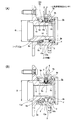
本発明の効果を確認する為に行なった、シミュレーション並びに考察に就いて説明する。このシミュレーション及び考察は、図1に示す様な複列アンギュラ型の玉軸受ユニットを構成する、複列に配置された各玉8a、8bの直径dとこれら各玉のピッチ円直径Dとの比d/Dが、アキシアル荷重Fyの変動に伴う上記各玉8a、8bの公転速度nc の変動に及ぼす影響を知り、上記比d/Dの適正範囲を知る為に行なった。図1中の(A)は上記比d/Dが比較的小さい(0.15)玉軸受ユニットを、同じく(B)はこの比d/Dが比較的大きい(0.25)玉軸受ユニットを、それぞれ示している。尚、図1に示した玉軸受ユニットは、駆動輪(FF車の前輪、FR車、RR車、MR車の後輪、4WD車の全車輪)用の玉軸受ユニットである為、従動輪(FF車の後輪、FR車、RR車、MR車の前輪)用の玉軸受ユニットである、前述の図5、9に示した構造と異なり、ハブ11aの中心部にスプライン孔15を設けている。但し、この様な玉軸受の構造の相違は、本発明の要旨には何ら関係するものではない。
The simulation and consideration performed to confirm the effect of the present invention will be described. This simulation and consideration are based on the ratio between the diameter d of each
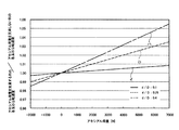
図1に示した構造にしろ、図5、9に示した構造にしろ、上記各玉8a、8bの直径dとこれら各玉のピッチ円直径Dとの比d/Dが異なると、アキシアル荷重Fyの変動に伴って、上記各玉8a、8bの公転速度nc が変動する程度が異なる。図2は、アキシアル荷重Fyと、これら各列の玉8a、8bの公転速度nc 同士の比との関係を示している。この様な図2中、実線イは上記比d/Dが0.1である場合の、破線ロは同じく0.25である場合の、鎖線ハは同じく0.4である場合の、それぞれ上記アキシアル荷重Fyと上記各列の公転速度nc 同士の比との関係を示している。尚、図2は、外輪1及び上記ハブ11aを中炭素鋼製とし、上記各玉8a、8bを軸受鋼製とした場合に就いて示している。
Regardless of the structure shown in FIG. 1 or the structures shown in FIGS. 5 and 9, if the ratio d / D between the diameter d of each
この様な図2から明らかな通り、上記各玉8a、8bの直径dとこれら各玉のピッチ円直径Dとの比d/Dを大きくすれば、上記アキシアル荷重Fyの変動に伴う、上記各列の玉8a、8bの公転速度nc (同士の比)の変動を大きくできる。図3は、これら各玉8a、8bの直径dとピッチ円直径Dとの比d/Dが、上記アキシアル荷重Fyの変動に伴うこれら各列の玉8a、8bの公転速度nc (同士の比)の変動に及ぼす影響を示している。この図3中の横軸は上記比d/Dを表している。又、縦軸は上記アキシアル荷重Fyの変動に伴って上記各列の玉8a、8bの公転速度nc 同士の比が変動する程度で、上記図2の各線イ〜ハの勾配の程度である。具体的には、上記アキシアル荷重Fyが7000N変化した場合に、上記公転速度nc 同士の比が変動する割合(ポイント[%])である。例えば、上記比d/Dが0.1の場合、上記アキシアル荷重Fyが7000N変化すると、上記公転速度nc 同士の比が凡そ1ポイント[%]変動する事を表している。
As is apparent from FIG. 2, if the ratio d / D between the diameter d of the
上述の様な図2、3から明らかな通り、上記アキシアル荷重Fyの変動に基づく上記各玉8a、8bの公転速度の変化を大きくし、このアキシアル荷重Fyの測定精度を向上させる為には、上記比d/Dを大きくすれば良い。逆に言えば、この比d/Dが小さ過ぎた場合には、上記アキシアル荷重Fyの測定精度を十分に確保できない。但し、上記比d/Dを大きくすべく、上記各玉8a、8bの直径dを大きくし過ぎると、玉軸受ユニット全体が大きくなったり(外輪1の外径を大きくする場合)、この外輪1やハブ11aの肉厚が小さくなり過ぎて、これら外輪1やハブ11aの耐久性が損なわれる可能性を生じる。又、上記比d/Dを大きくすべく、上記ピッチ円直径Dを小さくすると、モーメント荷重に対する剛性や転がり疲れ寿命が低下する可能性を生じる。従って、上記比d/Dは、むやみに大きくする事はできない。
As apparent from FIGS. 2 and 3 as described above, in order to increase the change in the revolving speed of the
そこで本発明者は、上記玉軸受ユニット本来の機能を確保しつつ、上記各玉8a、8bの公転速度nc の変化を大きくし、このアキシアル荷重Fyの測定精度を確保できる範囲を知る為の考察を行なった。
先ず、本発明をABS、TCS、VSC等の車両用走行安定化装置の制御に利用する事を考慮した場合、車両の走行状態を安定させる為には、上記アキシアル荷重Fyを検出する分解能は、1000N程度、好ましくは500N程度に抑える必要がある。分解能がこれよりも悪い(1000Nよりも大きな分解能でしか測定できない)と、走行安定性確保の為の制御に上記アキシアル荷重Fyを利用する意味がなくなる。又、この制御にこのアキシアル荷重Fyを利用する場合、このアキシアル荷重Fyの測定範囲に関しては、−1000N〜6000N程度(フルスケールを7000N程度)は必要である。
The present inventors have, while ensuring the ball bearing unit original function, the
First, in consideration of the use of the present invention for the control of vehicle travel stabilization devices such as ABS, TCS, VSC, etc., in order to stabilize the vehicle travel state, the resolution for detecting the axial load Fy is as follows: It is necessary to suppress to about 1000N, preferably about 500N. If the resolution is lower than this (measurement can only be performed with a resolution higher than 1000 N), there is no point in using the axial load Fy for the control for ensuring running stability. Further, when this axial load Fy is used for this control, about -1000N to 6000N (full scale is about 7000N) is necessary for the measurement range of this axial load Fy.
一方、上記アキシアル荷重Fyを検出する際には、公転速度検出用センサ6a、6bの検出誤差が存在する。例えば、これら両公転速度検出用センサ6a、6bを、前述の様な磁気検出素子を組み込んだアクティブ型の磁気センサとした場合、これら両公転速度検出用センサ6a、6bの検出誤差は0.2%程度考慮する必要がある。上記アキシアル荷重Fyの分解能がこの検出誤差よりも大きい(悪い)場合には、上記アキシアル荷重Fyによる制御の信頼性を十分に確保できなくなる可能性がある。例えば、このアキシアル荷重Fyの大きさを上記フルスケールの間で複数の階層(例えば7又は14の階層)に分けて判定し、その時に生じているアキシアル荷重Fyが属する階層に応じてABS、TCS、VSC等の車両用走行安定化装置の制御を行なう場合に、実際に作用しているアキシアル荷重Fyが属する階層と、演算器が算出したアキシアル荷重Fyの属する階層とが、2段階以上ずれる可能性を生じる。このアキシアル荷重Fyを検出する分解能を、上述した様な1000N程度、好ましくは500N程度にすれば、上述の様な2段階以上のずれを生じさせずに済む。そして、この様な2段階以上のずれを生じさせない為には、上記アキシアル荷重Fyが1000N(好ましくは500N)変動した場合に、上記各列の玉8a、8bの公転速度nc 同士の比が0.2ポイント[%]以上変動する構造とする必要がある。この場合に、上述した測定の全範囲(−1000N〜6000N、フルスケール:7000N)では、上記各列の玉8a、8bの公転速度nc 同士の比が1.4ポイント[%]以上変動する事が必要となる{∵0.2ポイント×(7000N/1000N)=1.4ポイント}。尚、1段階のずれは、実際に作用しているアキシアル荷重Fyが、階層分けの境界近傍に存在する可能性を考慮すれば、上記検出誤差が僅かでも存在する限り、なくす事はできない。
On the other hand, when detecting the axial load Fy, there is a detection error of the revolution
この様な前提で図3を見れば、上記各玉8a、8bの直径dとこれら各玉のピッチ円直径Dとの比d/Dを0.12以上にする必要がある事が分かる。即ち、上記図3の縦軸が1.4ポイントとなる上記比d/Dの値をこの図3の横軸から読み取れば、上記0.12なる値が導き出せる。又、アキシアル荷重Fyの分解能を、より好ましい値である500Nにする為には、上記比d/Dを0.2以上にすれば良い事も、上記図3から分かる。即ち、この比d/Dが0.2である場合、上記7000Nなるフルスケールの範囲で、上記各列の玉8a、8bの公転速度nc 同士の比が、2.8ポイント[%]変動する。この為、上記アキシアル荷重を500N程度の分解能で測定できる。
If FIG. 3 is seen on such a premise, it turns out that ratio d / D of the diameter d of each said
更に、上記比d/Dが0.4である場合、上記7000Nなるフルスケールの範囲で、上記各玉8a、8bの公転速度nc が凡そ6ポイント[%]変動する。この為、上記アキシアル荷重Fyを230N程度の分解能で測定できる。上記比d/Dを0.4よりも大きくすれば、このアキシアル荷重Fyの分解能をより良好にできる。但し、この分解能を上記230Nよりも良好にする必要性が乏しいだけでなく、上記比d/Dを0.4よりも大きくすべく、上記各玉8a、8bの直径dを大きくしたり、これら各玉のピッチ円直径Dを小さくしたりすると、玉軸受ユニット本来の性能が損なわれる。これに対して本願発明の場合には、上記比d/Dを0.12〜0.4としたので、上記玉軸受ユニット本来の性能を確保しつつ、上記アキシアル荷重Fyの測定精度を十分に確保できる。
Furthermore, if the above ratio d / D is 0.4, the range of the full scale made above 7000N, the
尚、より好ましくは、上記比d/Dを0.2〜0.3の範囲に規制する。この比d/Dをこの様に規制すれば、玉軸受ユニットの大型化や外輪1及びハブ11aの肉厚の過度の低下を防止しつつ、上記アキシアル荷重Fyの測定精度向上を図れる。
尚、前記図1に示した2例の玉軸受ユニットのうち、(A)に示した構造は、上記比d/Dが0.15であり、7000Nなるフルスケールの範囲での、上記各列の玉8a、8bの公転速度nc 同士の比の変化は2ポイント、分解能700Nである。
又、(B)に示した構造は、上記比d/Dが0.25であり、7000Nなるフルスケールの範囲での、上記各列の玉8a、8bの公転速度nc 同士の比の変化は3.5ポイント、分解能400Nである。
More preferably, the ratio d / D is restricted to a range of 0.2 to 0.3. By regulating the ratio d / D in this way, it is possible to improve the measurement accuracy of the axial load Fy while preventing an increase in the size of the ball bearing unit and an excessive decrease in the thickness of the
Of the two ball bearing units shown in FIG. 1, the structure shown in FIG. 1A has the ratio d / D of 0.15 and the above-mentioned each row in the full scale range of 7000N.
Further, the structure shown in (B) is a said ratio d / D is 0.25, in the range of full-scale consisting 7000N, each row of
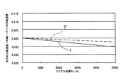
上記アキシアル荷重Fyの変動に伴って上記各列の玉8a、8bの公転速度nc 同士の比が変化する程度は、上述した様に、上記各玉8a、8bの直径dとこれら各玉のピッチ円直径Dとの比d/Dを大きくする事で大きくできる。但し、上記公転速度nc が変化する程度は、上記各玉8a、8bの直径dと、外輪1の内周面に形成した外輪軌道2、2並びにハブ11aの外周面に形成した内輪軌道13、13の断面の曲率半径rとの比(r/d)によっても調節できる。即ち、上記変化する程度は、図4に示す様に、この比r/dを変える事により、この変化する程度のリニアリティ(直線性)やゲインを変化させる事ができる。実際の場合、上記比r/dは0.505〜0.6の範囲で調節できる。上記図4中、実線イはこの比r/dが標準(中程度の値)の場合を、破線ロは同じく大きい場合を、鎖線ハは同じく小さい場合を、それぞれ示している。上記比r/dを上記範囲内でどの様な値とするかは、必要とするリニアリティ(直線性)、ゲイン(勾配)、アキシアル荷重Fyを測定可能とする範囲等に応じて設計的に定める。
Said axial load Fy each row of
又、上記各玉8a、8bの接触角を、インナー側(車体側)とアウター側(タイヤ側)とで互いに異ならせると、高荷重側の公転速度の変化が大きくなり、荷重を測定可能な範囲を、より高荷重まで広げられる。この場合、上記接触角は、20°〜50°で変更可能である。
又、上記各玉8a、8bに付与している予圧を変える事によっても、リニアリティ(直線性)やゲイン特性を変える事ができる。この場合に上記予圧は、980N〜9800N(100kgf 〜1000kgf )の範囲で変更可能である。
尚、上述の様な、上記アキシアル荷重Fyの変動に伴って上記各玉8a、8bの公転速度nc が変化する程度を変える方法は、それぞれ単独で採用しても、組み合わせて採用しても良い。
又、本発明を実施する場合、図示の様に、両列の玉8a、8bに関して直径dとピッチ円直径Dとの比d/Dを大きくするだけでなく、片側の列の比d/Dのみを大きくする事もできる。又、複列玉軸受ユニットに限らず、単列の玉軸受ユニットにも適用できる。
If the contact angles of the
Also, the linearity and gain characteristics can be changed by changing the preload applied to the
Incidentally, such as described above, said axial load Fy the
When the present invention is carried out, as shown in the figure, not only the ratio d / D between the diameter d and the pitch circle diameter D is increased for the
1 外輪
2 外輪軌道
3 取付孔
4、4a センサユニット
5、5a 先端部
6a、6b 公転速度検出用センサ
7、7a 回転速度検出用センサ
8a、8b 玉
9a、9b 保持器
10a、10b 公転速度検出用エンコーダ
11、11a ハブ
12、12a 回転速度検出用エンコーダ
13 内輪軌道
14 カバー
15 スプライン孔
DESCRIPTION OF
Claims (5)
Priority Applications (1)
| Application Number | Priority Date | Filing Date | Title |
|---|---|---|---|
| JP2004110889A JP2005291457A (en) | 2004-04-05 | 2004-04-05 | Ball bearing unit |
Applications Claiming Priority (1)
| Application Number | Priority Date | Filing Date | Title |
|---|---|---|---|
| JP2004110889A JP2005291457A (en) | 2004-04-05 | 2004-04-05 | Ball bearing unit |
Publications (1)
| Publication Number | Publication Date |
|---|---|
| JP2005291457A true JP2005291457A (en) | 2005-10-20 |
Family
ID=35324603
Family Applications (1)
| Application Number | Title | Priority Date | Filing Date |
|---|---|---|---|
| JP2004110889A Pending JP2005291457A (en) | 2004-04-05 | 2004-04-05 | Ball bearing unit |
Country Status (1)
| Country | Link |
|---|---|
| JP (1) | JP2005291457A (en) |
Cited By (4)
| Publication number | Priority date | Publication date | Assignee | Title |
|---|---|---|---|---|
| WO2007052805A1 (en) * | 2005-11-07 | 2007-05-10 | Ntn Corporation | Bearing device for wheel |
| JP2007131164A (en) * | 2005-11-10 | 2007-05-31 | Ntn Corp | Bearing device for wheel |
| US7614796B2 (en) | 2005-05-12 | 2009-11-10 | Ntn Corporation | Wheel support bearing assembly |
| CN101300143B (en) * | 2005-11-07 | 2010-05-26 | Ntn株式会社 | Bearing units for wheels |
Citations (3)
| Publication number | Priority date | Publication date | Assignee | Title |
|---|---|---|---|---|
| JPS5594541U (en) * | 1978-12-21 | 1980-06-30 | ||
| GB2382142A (en) * | 2001-11-16 | 2003-05-21 | Nsk Europ Technology Co Ltd | Wheel bearing assemblies incorporating sensing arrangements |
| WO2004022992A1 (en) * | 2002-09-06 | 2004-03-18 | Nsk Ltd. | Rolling bearing unit for supporting wheel |
-
2004
- 2004-04-05 JP JP2004110889A patent/JP2005291457A/en active Pending
Patent Citations (3)
| Publication number | Priority date | Publication date | Assignee | Title |
|---|---|---|---|---|
| JPS5594541U (en) * | 1978-12-21 | 1980-06-30 | ||
| GB2382142A (en) * | 2001-11-16 | 2003-05-21 | Nsk Europ Technology Co Ltd | Wheel bearing assemblies incorporating sensing arrangements |
| WO2004022992A1 (en) * | 2002-09-06 | 2004-03-18 | Nsk Ltd. | Rolling bearing unit for supporting wheel |
Cited By (9)
| Publication number | Priority date | Publication date | Assignee | Title |
|---|---|---|---|---|
| US7614796B2 (en) | 2005-05-12 | 2009-11-10 | Ntn Corporation | Wheel support bearing assembly |
| US7901143B2 (en) | 2005-05-12 | 2011-03-08 | Ntn Corporation | Wheel support bearing assembly |
| US8092095B2 (en) | 2005-05-12 | 2012-01-10 | Ntn Corporation | Wheel support bearing assembly |
| WO2007052805A1 (en) * | 2005-11-07 | 2007-05-10 | Ntn Corporation | Bearing device for wheel |
| CN101300143B (en) * | 2005-11-07 | 2010-05-26 | Ntn株式会社 | Bearing units for wheels |
| EP1950056A4 (en) * | 2005-11-07 | 2010-06-09 | Ntn Toyo Bearing Co Ltd | Bearing device for wheel |
| US8308371B2 (en) | 2005-11-07 | 2012-11-13 | Ntn Corporation | Bearing apparatus for a wheel of vehicle |
| EP2990216A1 (en) * | 2005-11-07 | 2016-03-02 | NTN Corporation | Bearing device for wheel |
| JP2007131164A (en) * | 2005-11-10 | 2007-05-31 | Ntn Corp | Bearing device for wheel |
Similar Documents
| Publication | Publication Date | Title |
|---|---|---|
| JP4940937B2 (en) | Rotating machine state quantity measuring device | |
| JP4543643B2 (en) | Load measuring device for rolling bearing units | |
| JP4887882B2 (en) | Displacement measuring device and load measuring device of rolling bearing unit | |
| JP2005291457A (en) | Ball bearing unit | |
| JP2005321236A (en) | Load measuring device for rolling bearing units | |
| JP2005283323A (en) | Load measuring device for rolling bearing units | |
| JP2006112595A (en) | Rolling bearing unit | |
| JP2006242241A (en) | Ball bearing unit | |
| JP2005098771A (en) | Load measuring device for rolling bearing units | |
| JP2006201157A (en) | Ball bearing unit with displacement measuring device and ball bearing unit with load measuring device | |
| JP2006144984A (en) | Rolling bearing unit | |
| JP2005091073A (en) | Rotational speed detecting device and load measuring device for rolling bearing unit | |
| JP2005308134A (en) | Rolling bearing unit with sensor for revolution speed detection | |
| JP4487528B2 (en) | Load measuring device for rolling bearing unit for wheel support | |
| JP4438494B2 (en) | Load measuring device for rolling bearing units | |
| JP4325376B2 (en) | Attitude stabilization device for vehicles | |
| JP2006317434A (en) | Displacement measuring device and load measuring device of rolling bearing unit | |
| JP4370884B2 (en) | Load measuring device for rolling bearing units | |
| JP2008051669A (en) | Rolling bearing unit with state quantity measuring device | |
| JP4487525B2 (en) | Load measuring device for rolling bearing units | |
| JP2005156507A (en) | Load measuring device for rolling bearing units | |
| JP2005090993A (en) | Load measuring device for rolling bearing units | |
| JP4941140B2 (en) | State quantity measuring device for rolling bearing units | |
| JP4370885B2 (en) | Load measuring device for rolling bearing units | |
| JP2005147905A (en) | Load measuring device for rolling bearing unit for wheel support |
Legal Events
| Date | Code | Title | Description |
|---|---|---|---|
| A621 | Written request for application examination |
Free format text: JAPANESE INTERMEDIATE CODE: A621 Effective date: 20070320 |
|
| RD04 | Notification of resignation of power of attorney |
Free format text: JAPANESE INTERMEDIATE CODE: A7424 Effective date: 20070320 |
|
| A977 | Report on retrieval |
Free format text: JAPANESE INTERMEDIATE CODE: A971007 Effective date: 20090115 |
|
| A131 | Notification of reasons for refusal |
Free format text: JAPANESE INTERMEDIATE CODE: A131 Effective date: 20090120 |
|
| A02 | Decision of refusal |
Free format text: JAPANESE INTERMEDIATE CODE: A02 Effective date: 20090526 |