EP4549722A2 - Abgasrückführungsventilanordnung - Google Patents
Abgasrückführungsventilanordnung Download PDFInfo
- Publication number
- EP4549722A2 EP4549722A2 EP25165148.5A EP25165148A EP4549722A2 EP 4549722 A2 EP4549722 A2 EP 4549722A2 EP 25165148 A EP25165148 A EP 25165148A EP 4549722 A2 EP4549722 A2 EP 4549722A2
- Authority
- EP
- European Patent Office
- Prior art keywords
- shaft
- pin
- assembly
- pin hole
- butterfly
- Prior art date
- Legal status (The legal status is an assumption and is not a legal conclusion. Google has not performed a legal analysis and makes no representation as to the accuracy of the status listed.)
- Pending
Links
Images







Classifications
-
- F—MECHANICAL ENGINEERING; LIGHTING; HEATING; WEAPONS; BLASTING
- F02—COMBUSTION ENGINES; HOT-GAS OR COMBUSTION-PRODUCT ENGINE PLANTS
- F02M—SUPPLYING COMBUSTION ENGINES IN GENERAL WITH COMBUSTIBLE MIXTURES OR CONSTITUENTS THEREOF
- F02M26/00—Engine-pertinent apparatus for adding exhaust gases to combustion-air, main fuel or fuel-air mixture, e.g. by exhaust gas recirculation [EGR] systems
- F02M26/65—Constructional details of EGR valves
-
- F—MECHANICAL ENGINEERING; LIGHTING; HEATING; WEAPONS; BLASTING
- F02—COMBUSTION ENGINES; HOT-GAS OR COMBUSTION-PRODUCT ENGINE PLANTS
- F02M—SUPPLYING COMBUSTION ENGINES IN GENERAL WITH COMBUSTIBLE MIXTURES OR CONSTITUENTS THEREOF
- F02M26/00—Engine-pertinent apparatus for adding exhaust gases to combustion-air, main fuel or fuel-air mixture, e.g. by exhaust gas recirculation [EGR] systems
- F02M26/13—Arrangement or layout of EGR passages, e.g. in relation to specific engine parts or for incorporation of accessories
- F02M26/22—Arrangement or layout of EGR passages, e.g. in relation to specific engine parts or for incorporation of accessories with coolers in the recirculation passage
- F02M26/23—Layout, e.g. schematics
- F02M26/28—Layout, e.g. schematics with liquid-cooled heat exchangers
-
- F—MECHANICAL ENGINEERING; LIGHTING; HEATING; WEAPONS; BLASTING
- F02—COMBUSTION ENGINES; HOT-GAS OR COMBUSTION-PRODUCT ENGINE PLANTS
- F02M—SUPPLYING COMBUSTION ENGINES IN GENERAL WITH COMBUSTIBLE MIXTURES OR CONSTITUENTS THEREOF
- F02M26/00—Engine-pertinent apparatus for adding exhaust gases to combustion-air, main fuel or fuel-air mixture, e.g. by exhaust gas recirculation [EGR] systems
- F02M26/13—Arrangement or layout of EGR passages, e.g. in relation to specific engine parts or for incorporation of accessories
- F02M26/22—Arrangement or layout of EGR passages, e.g. in relation to specific engine parts or for incorporation of accessories with coolers in the recirculation passage
- F02M26/29—Constructional details of the coolers, e.g. pipes, plates, ribs, insulation or materials
- F02M26/32—Liquid-cooled heat exchangers
-
- F—MECHANICAL ENGINEERING; LIGHTING; HEATING; WEAPONS; BLASTING
- F02—COMBUSTION ENGINES; HOT-GAS OR COMBUSTION-PRODUCT ENGINE PLANTS
- F02M—SUPPLYING COMBUSTION ENGINES IN GENERAL WITH COMBUSTIBLE MIXTURES OR CONSTITUENTS THEREOF
- F02M26/00—Engine-pertinent apparatus for adding exhaust gases to combustion-air, main fuel or fuel-air mixture, e.g. by exhaust gas recirculation [EGR] systems
- F02M26/45—Sensors specially adapted for EGR systems
- F02M26/48—EGR valve position sensors
-
- F—MECHANICAL ENGINEERING; LIGHTING; HEATING; WEAPONS; BLASTING
- F02—COMBUSTION ENGINES; HOT-GAS OR COMBUSTION-PRODUCT ENGINE PLANTS
- F02M—SUPPLYING COMBUSTION ENGINES IN GENERAL WITH COMBUSTIBLE MIXTURES OR CONSTITUENTS THEREOF
- F02M26/00—Engine-pertinent apparatus for adding exhaust gases to combustion-air, main fuel or fuel-air mixture, e.g. by exhaust gas recirculation [EGR] systems
- F02M26/52—Systems for actuating EGR valves
- F02M26/53—Systems for actuating EGR valves using electric actuators, e.g. solenoids
- F02M26/54—Rotary actuators, e.g. step motors
-
- F—MECHANICAL ENGINEERING; LIGHTING; HEATING; WEAPONS; BLASTING
- F02—COMBUSTION ENGINES; HOT-GAS OR COMBUSTION-PRODUCT ENGINE PLANTS
- F02M—SUPPLYING COMBUSTION ENGINES IN GENERAL WITH COMBUSTIBLE MIXTURES OR CONSTITUENTS THEREOF
- F02M26/00—Engine-pertinent apparatus for adding exhaust gases to combustion-air, main fuel or fuel-air mixture, e.g. by exhaust gas recirculation [EGR] systems
- F02M26/52—Systems for actuating EGR valves
- F02M26/55—Systems for actuating EGR valves using vacuum actuators
- F02M26/56—Systems for actuating EGR valves using vacuum actuators having pressure modulation valves
- F02M26/57—Systems for actuating EGR valves using vacuum actuators having pressure modulation valves using electronic means, e.g. electromagnetic valves
-
- F—MECHANICAL ENGINEERING; LIGHTING; HEATING; WEAPONS; BLASTING
- F02—COMBUSTION ENGINES; HOT-GAS OR COMBUSTION-PRODUCT ENGINE PLANTS
- F02M—SUPPLYING COMBUSTION ENGINES IN GENERAL WITH COMBUSTIBLE MIXTURES OR CONSTITUENTS THEREOF
- F02M26/00—Engine-pertinent apparatus for adding exhaust gases to combustion-air, main fuel or fuel-air mixture, e.g. by exhaust gas recirculation [EGR] systems
- F02M26/65—Constructional details of EGR valves
- F02M26/66—Lift valves, e.g. poppet valves
- F02M26/67—Pintles; Spindles; Springs; Bearings; Sealings; Connections to actuators
-
- F—MECHANICAL ENGINEERING; LIGHTING; HEATING; WEAPONS; BLASTING
- F02—COMBUSTION ENGINES; HOT-GAS OR COMBUSTION-PRODUCT ENGINE PLANTS
- F02M—SUPPLYING COMBUSTION ENGINES IN GENERAL WITH COMBUSTIBLE MIXTURES OR CONSTITUENTS THEREOF
- F02M26/00—Engine-pertinent apparatus for adding exhaust gases to combustion-air, main fuel or fuel-air mixture, e.g. by exhaust gas recirculation [EGR] systems
- F02M26/65—Constructional details of EGR valves
- F02M26/70—Flap valves; Rotary valves; Sliding valves; Resilient valves
-
- F—MECHANICAL ENGINEERING; LIGHTING; HEATING; WEAPONS; BLASTING
- F02—COMBUSTION ENGINES; HOT-GAS OR COMBUSTION-PRODUCT ENGINE PLANTS
- F02M—SUPPLYING COMBUSTION ENGINES IN GENERAL WITH COMBUSTIBLE MIXTURES OR CONSTITUENTS THEREOF
- F02M26/00—Engine-pertinent apparatus for adding exhaust gases to combustion-air, main fuel or fuel-air mixture, e.g. by exhaust gas recirculation [EGR] systems
- F02M26/65—Constructional details of EGR valves
- F02M26/72—Housings
-
- F—MECHANICAL ENGINEERING; LIGHTING; HEATING; WEAPONS; BLASTING
- F02—COMBUSTION ENGINES; HOT-GAS OR COMBUSTION-PRODUCT ENGINE PLANTS
- F02M—SUPPLYING COMBUSTION ENGINES IN GENERAL WITH COMBUSTIBLE MIXTURES OR CONSTITUENTS THEREOF
- F02M26/00—Engine-pertinent apparatus for adding exhaust gases to combustion-air, main fuel or fuel-air mixture, e.g. by exhaust gas recirculation [EGR] systems
- F02M26/65—Constructional details of EGR valves
- F02M26/74—Protection from damage, e.g. shielding means
-
- F—MECHANICAL ENGINEERING; LIGHTING; HEATING; WEAPONS; BLASTING
- F02—COMBUSTION ENGINES; HOT-GAS OR COMBUSTION-PRODUCT ENGINE PLANTS
- F02M—SUPPLYING COMBUSTION ENGINES IN GENERAL WITH COMBUSTIBLE MIXTURES OR CONSTITUENTS THEREOF
- F02M26/00—Engine-pertinent apparatus for adding exhaust gases to combustion-air, main fuel or fuel-air mixture, e.g. by exhaust gas recirculation [EGR] systems
- F02M26/65—Constructional details of EGR valves
- F02M26/72—Housings
- F02M26/73—Housings with means for heating or cooling the EGR valve
Definitions
- the present disclosure generally relates to valve assemblies and, more particularly, to exhaust gas recirculation (EGR) valve assemblies.
- EGR exhaust gas recirculation
- EGR valve assemblies are used to control the recirculation of exhaust gases through combustion chambers within internal combustion engines. Exhaust gas recirculation that is improperly controlled may result in air/fuel mixtures that are too rich or too lean for efficient combustion.
- a valve assembly such as an EGR valve assembly, may generally include a valve housing having a flow housing portion defining a flow passage extending therethrough and along a flow axis, a gear assembly housing portion coupled to the flow housing portion, and a shaft bore extending between the flow passage and the gear assembly housing portion; a driven shaft positioned in the shaft bore and extending along a shaft axis generally transverse to the flow axis; a shaft bearing disposed in the shaft bore and pivotably supporting the driven shaft; a butterfly member coupled to the driven shaft for pivoting movement with the driven shaft about the shaft axis, the butterfly member being pivotable between a closed position, in which flow of gas through the flow passage is inhibited, and an open position; an electronics housing coupled to the valve housing; a printed circuit board supported in the electronics housing; a drive pinion extending between the electronics housing and the gear assembly housing portion, the drive pinion being drivingly coupled to the driven shaft; and a sealing assembly to inhibit flow of gas from the flow passage into the electronics housing.
- the sealing assembly may include a first seal positioned in the shaft bore and along the driven shaft to provide a seal between the driven shaft and the shaft bore, the first seal being disposed between the flow passage and the shaft bearing, a second seal positioned in the shaft bore and along the driven shaft to provide a seal between the driven shaft and the shaft bore, the second seal being disposed between the shaft bearing and the electronics housing, a plate engaged between the valve housing and the electronics housing, the plate defining an opening therethrough, the drive pinion extending through the opening into the gear assembly housing portion, and a sealed bearing supported by the plate and pivotably supporting the drive pinion in the opening, the sealed bearing providing a seal between the drive pinion and the plate.
- a valve assembly such as an EGR valve assembly, may generally include a valve housing having a flow housing portion defining a flow passage extending therethrough and along a flow axis, the valve housing defining a shaft bore extending from the flow passage; a shaft positioned in the shaft bore and extending along a shaft axis generally transverse to the flow axis; a bearing disposed in the shaft bore and pivotably supporting the shaft; a butterfly member coupled to the shaft for pivoting movement with the shaft about the shaft axis, the butterfly member being pivotable between a closed position, in which flow of gas through the flow passage is inhibited, and an open position; a seal positioned in the shaft bore and along the shaft and disposed in the shaft bore to provide a seal between the shaft and the shaft bore and inhibit gas flow from the flow passage through the shaft bore, the seal being proximate the bearing; and a coolant jacket formed in the valve housing around the shaft bore and configured to receive coolant to cool at least a portion of the valve housing proximate
- a method of assembling a butterfly assembly for a valve assembly may be provided.
- the butterfly assembly may include a shaft, a butterfly member defining a shaft bore, and a pin.
- the method may generally include inserting the shaft into the shaft bore of the butterfly member; after inserting the shaft, drilling a pin hole through the butterfly member and the shaft; and ramming the pin into the pin hole, ramming causing material of the pin, the butterfly member and the shaft to deform and form a unitary structure.
- functionality described herein as being performed by one component may be performed by multiple components in a distributed manner. Likewise, functionality performed by multiple components may be consolidated and performed by a single component. Similarly, a component described as performing particular functionality may also perform additional functionality not described herein. For example, a device or structure that is "configured" in a certain way is configured in at least that way but may also be configured in ways that are not listed.
- non-transitory computer-readable medium comprises all computer-readable media but does not consist of a transitory, propagating signal. Accordingly, non-transitory computer-readable medium may include, for example, a hard disk, a CD-ROM, an optical storage device, a magnetic storage device, a ROM (Read Only Memory), a RAM (Random Access Memory), register memory, a processor cache, or any combination thereof.
- modules and logical structures described are capable of being implemented in software executed by a microprocessor or a similar device or of being implemented in hardware using a variety of components including, for example, application specific integrated circuits ("ASICs").
- ASICs application specific integrated circuits
- Terms like “controller” and “module” may include or refer to both hardware and/or software.
- Capitalized terms conform to common practices and help correlate the description with the coding examples, equations, and/or drawings. However, no specific meaning is implied or should be inferred simply due to the use of capitalization. Thus, the claims should not be limited to the specific examples or terminology or to any specific hardware or software implementation or combination of software or hardware.
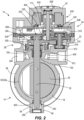
- FIGS. 1-2 illustrate a valve assembly 10, such as an exhaust gas recirculation (EGR) valve assembly and, specifically, a hot-side exhaust gas recirculation valve assembly, operable to control exhaust flow to the engine intake (not shown), thereby controlling the air-to-fuel ratio and reducing engine emissions.
- the valve assembly 10 may be another type of valve assembly, for example, an exhaust brake valve assembly.
- the valve assembly 10 includes a valve housing 14 having a flow housing portion 18 and a gear assembly housing portion 22, a butterfly flap or butterfly member 26, and a shaft 30 coupled to the butterfly member 26.
- the butterfly member 26 is supported by the shaft 30 for pivoting movement therewith between an open position, a closed position, in which gas flow is inhibited, and a plurality of intermediate flow positions.
- the valve assembly 10 further includes a bearing assembly 34, a seal assembly 38, and an electronics housing 42 coupled to the valve housing 14 by fasteners 46 (e.g., screws).
- the flow housing portion 18 is formed with a generally cylindrical shape between opposite ends 50, 54, each having an exterior flange 58.
- the flow housing portion 18 defines (see FIG. 3 ) a flow passage 62 extending therethrough between a first flow opening 70 (e.g., an inlet) at the first end 50 and a second flow opening 74 (e.g., an outlet, see FIG. 5 ) at the second end 54.
- the flow passage 62 defines a flow axis 78 extending in a first direction between the openings 70, 74.
- a sealing flange 82 extends from an interior surface 86 into the flow passage 62, and, in the closed position, the butterfly member 26 engages the sealing flange 82 to inhibit gas flow through the flow passage 62.
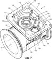
- the gear assembly housing portion 22 is integrally formed with the flow housing portion 18, on a side opposite the protrusion 90.
- the gear assembly housing portion 22 defines a gear assembly cavity 110 and a bore 112 extending from the flow passage 62 into the gear assembly cavity 110.
- the bore 112 is coaxial with the bore 94 along a shaft bore axis 116 transverse to the flow axis 78.
- the bore 112 has an opening 120 through the interior surface 86 of the flow passage 62 and an opposite opening 124 into the gear assembly cavity 110.
- a seal seat 128 is formed proximate the opening 120, and a bearing seat 132 is formed adjacent the seal seat 128.
- Another seal seat 136 is formed proximate the opening 124 into the gear assembly cavity 110.
- the bore openings 98, 120 are positioned proximate the center of the flow passage 62 and divide the sealing flange 82 into flange halves 82a, 82b ( FIG. 2 and 5 , respectively). As such, the flange halves 82a, 82b extend along the interior surface 86 of the flow passage 62 between the bore openings 98, 120.
- the gear assembly cavity 110 is defined by walls 140, which extend from the flow housing portion 18 and terminate at an end surface 144 defining a gear assembly opening 148.
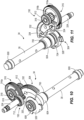
- the gear assembly cavity 110 is structured to receive and support a gear assembly 150 (see FIGS. 10-11 ).
- a base wall 152 is formed along a bottom portion of the gear assembly cavity 110 and radially surrounds the bore 112.
- the walls 140 include a first step 156 extending from the base wall 152, a second step 164 formed on one side of the first step 156, and a third step 168 formed on the other side of the first step 156.
- a third bearing seat 184 extends through the steps 156, 164 and is spaced from the bore 112.
- FIGS. 12-15 illustrate the butterfly assembly.
- the butterfly member 26 has a body 200 formed by a first plate 204 and a second plate 208 with a shaft bore 212 defined therethrough.
- the plates 204, 208 have a substantially circular shape to conform to the flow passage 62 of the flow housing portion 18.
- the plates 204, 208 are offset with a portion of the first plate 204 extending beyond the second plate 208 to form a first contact edge 216 on one side of the butterfly member 26 and a portion of the second plate 208 extending beyond the first plate 204 to form a second contact edge 220 on the other side of the butterfly member 26.
- the butterfly member 26 is drilled to define a number of pin holes 224 (two, in the illustrated construction) extending through the first plate 204 and has a corresponding number of protrusions 228 (two shown) extending from the second plate 208.
- the pin holes 224 and the protrusions 228 are aligned through a center of the shaft bore 212.
- the shaft 30 has a body 232 with opposite ends 236, 240 extending along a shaft axis 242.
- a protrusion 244 extends from the first end 236, and a chamfered edge is formed on the second end 240.
- the body 232 has a first diameter, while the protrusion 244 has a smaller second diameter.
- the shaft 30 is drilled to define a number of pin holes 248 corresponding to the pin holes 224 (two shown) through the center of the body 232.
- the butterfly member 26 when assembling the butterfly assembly, is positioned in the flow passage 62, and the shaft 30 is inserted into the shaft bore 212 of the butterfly member 26 with the first end 236 extending a greater distance from the body 200 of the butterfly member 26 than the second end 240.
- the pin hole(s) 224, 248 are then drilled into the butterfly member 26 and the shaft 30.
- the pin hole(s) 224, 248 have a diameter of between about 2 millimeters (mm) and about 12 mm.
- each pin 252 is inserted into each set of pin holes 224, 248.
- Each pin 252 has a diameter about 5% less than the diameter of the pin holes 224, 248 so that the pin 252 easily slips into the pin holes 224, 248 to accommodate loose, low cost tolerances between the components.
- Each pin 252 is fully inserted into the pin holes 224, 248 to be guided.
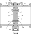
- the pin 252 is then pressed (see FIG. 3B ) between a tool (not shown) positioned through the pin hole 224 and the inner surface of the protrusion 228 to cause the pin 252 to "swell" (e.g., increase in diameter) to match the form and diameter of the pin holes 224, 248, causing material of the pin 252, the butterfly member 26 (proximate the pin hole 224) and the shaft 30 (proximate the pin hole 248) to deform and form a unitary structure.
- the pin holes 224, 248 fully guide the pin 252 during pressing so that the pin 252 is in a shear condition and no bending stress is applied.
- each pin 252 is pressed into the corresponding pin hole 224, 248 with a force of between about 1,500 pounds-force (lbf) and about 2,500 lbf. (e.g., about 2,200 lbf. (9,800 newtons (N))).
- the pressing process is conducted for between about 5 seconds (s) and about 30 s.
- the components of the butterfly assembly should expand and contract at the same rate. Components formed of materials with different coefficients of thermal expansion will expand and contract at different rates, causing the connection to loosen.
- the material(s) e.g., austenitic stainless steel, ferritic stainless steel, martensitic stainless steel, tool steel, etc., depending on application requirements
- the shaft 30, and the pin(s) 252 are configured to have substantially equal coefficients of thermal expansion.
- the butterfly assembly arranged centrally within the flow housing portion 18.
- the butterfly member 26 is arranged within the flow passage 62 so that, in the closed position, the second contact edge 220 sealingly engages the flange half 82a and the first contact edge 216 sealingly engages the flange half 82b.
- the butterfly assembly is configured to be pivoted about the axis 116 to control the flow of gas through the flow passage 62.
- the body 232 of the shaft 30 extends through the bore 112 with the first end 236 positioned in the gear assembly cavity 110, and the second end 240 of the body 232 is positioned in the bore 94.
- a closure member 260 is arranged in the seat 108 to inhibit debris, contaminants, etc., from entering the bore 94.
- the shaft 30 is pivotably coupled to the gear assembly 150.
- the gear assembly 150 includes a spring 300, a shaft gear 304, a rod gear 316, a rod 318, and a pinion gear 320 integrally formed on a motor shaft 324.
- the spring 300 is positioned along the base wall 152 and extends about the bore 112. One end of the spring 300 engages a notch 326 formed in the first step 156 (shown in FIG. 7 ) and the opposite end engages the shaft gear 304.
- the shaft gear 304 is coupled for rotation with the shaft 30 and is positioned on the first step 156.
- the shaft gear 304 has a central portion 328 receiving the shaft 30 and a gear portion 332 (e.g., a spur gear) extending from the central portion 328.
- a pair of abutment surfaces 334 are formed on the central portion 328, with one abutment surface 334 configured to engage the end of the spring 300 to bias the butterfly assembly to the closed position.
- the rod gear 316 receives the rod 318 as the rod 318 is seated in the third bearing seat 184.
- the rod gear 316 is positioned along the second step 164.
- the rod gear 316 includes a first gear portion 316a and a second gear portion 316b extending from a center of the first gear portion 316a.
- the first gear portion 316a is configured to intermesh and be driven by the pinion gear 320 (e.g., a spur gear).
- the second gear portion 316b is configured to intermesh and drive the shaft gear 304 to rotate the shaft 30.
- the electronics housing 42 is illustrated in FIGS. 1-3A and is configured to house and support an actuator assembly 400 operably coupled to the gear assembly 150 and the butterfly assembly.
- the actuator assembly 400 includes a motor 404 and a printed circuit board (PCB) 408 positioned within an electronics assembly cavity 412 of the electronics housing 42.
- PCB printed circuit board
- the illustrated motor 404 includes a brushless DC motor operable to drive the motor shaft 324.
- the motor shaft 324 extends from the electronics housing 42 and into the gear assembly housing portion 22, so that the pinion gear 320 intermeshes and drives the first gear portion 316a of the rod gear 316 when the motor 404 is actuated.
- the PCB 408 is fixed to the electronics housing 42 by fasteners (not shown), thereby securing the PCB 408 and the motor 404 within the electronics assembly cavity 412.
- a connector 420 on the electronics housing 42 is configured to provide power and communication with electronic components of the actuator assembly 400.
- the PCB 408 supports electronic components (not shown) including a controller with an electronic processor, a motor controller, one or more sensors, etc.
- the controller is electrically and/or communicatively connected to a variety of modules or components of the valve assembly 10.
- the controller includes a plurality of electrical and electronic components that provide power, operational control, and protection to the components and modules within the controller and/or the valve assembly 10.
- the controller includes, among other things, the electronic processor (a programmable electronic microprocessor, microcontroller, or similar device), a memory (not shown), and an input/output (I/O) interface (not shown).
- the electronic processor is communicatively coupled to the memory and the I/O interface.
- the controller may be implemented in several independent controllers each configured to perform specific functions or sub-functions. Additionally, the controller may contain sub-modules that include additional electronic processors, memory, or application specific integrated circuits (ASICs) for handling communication functions, processing of signals, and application of the methods listed below. In other embodiments, the controller includes additional, fewer, or different components.
- ASICs application specific integrated circuits
- the memory is, for example, a non-transitory, machine-readable memory.
- the memory includes, for example, one or more non-transitory machine-readable media, a program storage area and a data storage area.
- the program storage area and the data storage area can include combinations of different types of memory, such as read-only memory (ROM) and random access memory (RAM).
- ROM read-only memory
- RAM random access memory
- data is stored in a non-volatile random-access memory (NVRAM) of the memory.
- NVRAM non-volatile random-access memory
- Various non-transitory computer readable media for example, magnetic, optical, physical, or electronic memory may be used.
- the memory includes an input controller engine (not shown; for example, software or a set of computer-readable instructions that determines functions to be executed in response to inputs) and sensor assembly functions (for example, software or a set of computer-readable instructions that provide functionality to the valve assembly 10).
- an input controller engine (not shown; for example, software or a set of computer-readable instructions that determines functions to be executed in response to inputs)
- sensor assembly functions for example, software or a set of computer-readable instructions that provide functionality to the valve assembly 10).
- the electronic processor is communicatively coupled to the memory and executes software instructions that are stored in the memory, or stored in another non-transitory computer readable medium such as another memory or a disc.
- the software may include one or more applications, program data, filters, rules, one or more program modules, and other executable instructions.
- the memory stores predetermined functions as well as other functions that are executed to provide a sensor assembly functionality, within the program storage area.
- the I/O interface is communicatively coupled to components external to the controller and coordinates the communication of information between the electronic processor and other components of the valve assembly 10.
- information received from an input component, an external device, etc. is provided to the electronic processor to assist in determining functions to be executed and outputs to be provided.
- the determined functionality is executed with the electronic processor with the software located the memory.
- Communication components are on the PCB 408 and are configured to communicate with external devices (e.g., an external control device).
- external devices e.g., an external control device.
- the communication components are configured to transmit and receive signals with one or more external devices via a wired connection through the connector 420.
- the motor 404 is operated to rotate the motor shaft 324, thereby driving the gear assembly 150 and the shaft 30 to pivot the butterfly member 26.
- the butterfly member 26 is pivoted between the closed position and the open position to control exhaust gas flow through the flow passage 62. In an open position, exhaust gas flows from the inlet 70 to the outlet 74.
- the electronics housing 42 includes a mid-plate 424 fastened between the valve housing 14 and the electronics housing 42.
- the mid-plate 424 is configured to provide a seal between the valve housing 14 and the electronics housing 42 to inhibit contaminants from entering the electronics housing 42.
- the mid-plate 424 has a top surface 428 facing towards the electronics housing 42 and a bottom surface 432 facing towards the electronics housing 42.
- First fastener holes 436, second fastener holes 440, and pin holes 444 extend through the mid-plate 424.
- the fastener holes 436 receive the fasteners 46 (see FIG. 1 ) to couple the mid-plate 424 between the valve housing 14 and the electronics housing 42.
- the fastener holes 440 receive fasteners (not shown) to couple the mid-plate 424 to the electronics housing 42.
- the pin holes 444 receive to receive pins (not shown) configured to be inserted into the valve housing 14 and the electronics housing 42.
- the mid-plate 424 defines (see FIG. 8 ) a motor shaft opening 448 configured to allow the motor shaft 324 to extend through the mid-plate 424 and into the gear assembly housing portion 22.
- a wall protrusion 452 extends from the top surface 428 and is concentric with the motor shaft opening 448.
- the wall protrusion 452 forms a bearing seat 456 in the spacing between the motor shaft opening 448 and the wall protrusion 452.
- a groove 460 is formed in the top surface 428 and extends around a periphery 464 of the mid-plate 424.
- a plurality of projections 468, a first circular wall 472, and a second circular wall 476 extend from the bottom surface 432 of the mid-plate 424.
- the projections 468 are spaced apart and have a rectangular shape.
- the first circular wall 472 forms a bearing seat 480 that extends into the mid-plate 424 past the top surface 428 (see FIG. 8 ).
- the rod 318 extends into the bearing seat 480 against a bottom surface 484, thereby supporting the rod gear 316 for rotation.
- the second circular wall 476 forms a bearing seat 488 receiving the first end 236 of the shaft 30.
- a groove 492 is formed in the bottom surface 432 and extends around the periphery 464 of the mid-plate 424.
- the bearing assembly 34 is illustrated in FIGS. 2-11 .
- the bearing assembly 34 includes multiple bearings arranged on the shaft 30 and the gear assembly 150.
- a first shaft bearing 600 is arranged in the bearing seat 104 and supports the second end 240 of the shaft 30.
- a needle bearing 604 is arranged in the bearing seat 132 along the body 232 of the shaft 30.
- a second shaft bearing 608 is arranged in the bearing seat 488 and supports the first end 236 of the shaft 30.
- the bearings 600, 604, 608 rotatably support the shaft 30 within the valve housing 14.
- a first rod bearing 612 is arranged in the third bearing seat 184 and supports one end of the rod 318, while the second rod bearing 616 is arranged in the bearing seat 480 and supports the other end of the rod 318.
- the rod gear 316 is positioned along the rod 318 between the rod bearings 612, 616.
- a motor shaft bearing 624 is arranged in a bearing seat 628 formed in the electronics assembly cavity 412 to further support the motor shaft 324.
- the bore 112 provides a potential path from the flow passage 62 toward the electronics housing 42 for leakage of exhaust gas including constituents (e.g., sulfur) which are harmful to and may damage electronic components (e.g., the PCB 408 and its components).
- the valve assembly 10 includes the seal assembly 38 between the flow passage 62 and the electronics housing 42.
- FIGS. 2 , 4 and 10-11 illustrate the seal assembly 38.
- the seal assembly 38 includes multiple sealing components positioned along a path from the flow passage 62, through the gear assembly housing 22 and into the electronics housing 42.
- a first seal 700 (e.g., an O-ring, as illustrated) is arranged in the seal seat 128 between the shaft 30 and the bore 112 and along the shaft 30 between the flow passage 62 and the needle bearing 604.
- a second seal 704 (e.g., a rotary shaft seal, as illustrated) is arranged in the seal seat 136 between the shaft 30 and the bore 112 and along the shaft 30 between the needle bearing 604 and the gear assembly cavity 110.
- the needle bearing 604 is disposed between the first and second seals 700, 704.
- the seals 700, 704 are configured to inhibit exhaust gas leakage along the bore 112 and into the gear assembly housing 22.
- a pair of molded seals 708 are respectively inserted into the grooves 460, 492 of the mid-plate 424.
- the seal 708 in the groove 460 engages between the mid-plate 424 and the electronics housing 42 while the seal 708 in the groove 492 engages between the mid-plate 424 and the valve housing 14.
- a sealed bearing 712 is arranged in the bearing seat 456 to support the motor shaft 324 on the mid-plate 424.
- the sealed bearing 712 provides a seal between the mid-plate 424 and the motor shaft 324 to inhibit exhaust gas leakage along the motor shaft 324 into the electronics housing 42, if any exhaust gas were to leak through the bore 112.
- the exhaust gas through the valve assembly 10 has a temperature of about 600 °C (1,112 °F). Such high temperatures can impair operation and damage components of the valve assembly 10, such as for example, the bearing assembly 34, the seal assembly 38, etc.
- a coolant jacket assembly 800 formed in the valve housing 14, is configured to receive coolant (e.g., anti-freeze).
- the coolant jacket assembly 800 includes a coolant inlet 804, a coolant intermediate portion 808, and a coolant outlet 812 to form a coolant channel.
- the illustrated coolant channel is proximate the first seal 700 and the needle bearing 604, and the coolant intermediate portion 808 is formed as a hollow loop that encircles the first seal 700 and the needle bearing 604. As shown in FIG. 4 , the coolant channel extends transverse to the flow channel 62.
- the coolant intermediate portion 808 has an extent along the axis 116, and the seal 700, along with a majority of the needle bearing 604, is within this extent. Also, there is a portion of the coolant intermediate portion 808 positioned axially between the flow passage 62 and the seal 700.
- Coolant enters the housing assembly 14 through the coolant inlet 804 and flows into the coolant intermediate portion 808 to cool the housing assembly 14, the first seal 700 and the needle bearing 604. After flowing through the coolant intermediate portion 808, the coolant exits through the coolant outlet 812.
- Providing the coolant jacket assembly 800 reduces the temperature experienced by components of the valve assembly 10 (e.g., to between about 200 °C and about 300 °C) while high temperature exhaust gas flows through the flow passage 62.
Landscapes
- Engineering & Computer Science (AREA)
- Chemical & Material Sciences (AREA)
- Combustion & Propulsion (AREA)
- Mechanical Engineering (AREA)
- General Engineering & Computer Science (AREA)
- Health & Medical Sciences (AREA)
- Toxicology (AREA)
- Analytical Chemistry (AREA)
- Physics & Mathematics (AREA)
- Electromagnetism (AREA)
- Lift Valve (AREA)
Applications Claiming Priority (2)
| Application Number | Priority Date | Filing Date | Title |
|---|---|---|---|
| US202363485722P | 2023-02-17 | 2023-02-17 | |
| EP24155372.6A EP4417808A3 (de) | 2023-02-17 | 2024-02-01 | Abgasrückführungsventilanordnung |
Related Parent Applications (1)
| Application Number | Title | Priority Date | Filing Date |
|---|---|---|---|
| EP24155372.6A Division EP4417808A3 (de) | 2023-02-17 | 2024-02-01 | Abgasrückführungsventilanordnung |
Publications (2)
| Publication Number | Publication Date |
|---|---|
| EP4549722A2 true EP4549722A2 (de) | 2025-05-07 |
| EP4549722A3 EP4549722A3 (de) | 2025-07-09 |
Family
ID=89833988
Family Applications (2)
| Application Number | Title | Priority Date | Filing Date |
|---|---|---|---|
| EP24155372.6A Pending EP4417808A3 (de) | 2023-02-17 | 2024-02-01 | Abgasrückführungsventilanordnung |
| EP25165148.5A Pending EP4549722A3 (de) | 2023-02-17 | 2024-02-01 | Abgasrückführungsventilanordnung |
Family Applications Before (1)
| Application Number | Title | Priority Date | Filing Date |
|---|---|---|---|
| EP24155372.6A Pending EP4417808A3 (de) | 2023-02-17 | 2024-02-01 | Abgasrückführungsventilanordnung |
Country Status (3)
| Country | Link |
|---|---|
| US (2) | US12241435B2 (de) |
| EP (2) | EP4417808A3 (de) |
| CN (1) | CN118517356A (de) |
Family Cites Families (41)
| Publication number | Priority date | Publication date | Assignee | Title |
|---|---|---|---|---|
| US2747224A (en) | 1951-06-11 | 1956-05-29 | Polymer Corp | Method and apparatus for continously forming elongated shapes from thermoplastic materials |
| US2747222A (en) | 1951-06-11 | 1956-05-29 | Polymer Corp | Production of nylon rod |
| GB744976A (en) | 1951-06-11 | 1956-02-15 | Polymer Corp | Improvements in or relating to equipment and method for making elongated shapes fromsynthetic linear polyamides |
| DE1214868B (de) | 1951-06-11 | 1966-04-21 | Polymer Corp | Verfahren und Vorrichtung zum Herstellen blasenfreier Stangen, insbesondere aus einem hochschmelzenden Polyamid |
| LU32423A1 (de) | 1952-08-06 | 1900-01-01 | ||
| FR2398940A1 (fr) | 1977-07-26 | 1979-02-23 | Amri | Double joint torique flexible |
| DE1404442B2 (de) | 1952-08-06 | 1969-11-13 | ||
| CA1007259A (en) | 1974-01-17 | 1977-03-22 | Westinghouse Electric Corporation | Shaft sealing device |
| US3979104A (en) | 1974-01-17 | 1976-09-07 | Westinghouse Electric Corporation | Shaft sealing device for a butterfly valve |
| US4022424A (en) | 1975-09-29 | 1977-05-10 | General Electric Company | Shaft bearing and seals for butterfly valves |
| US4225112A (en) | 1978-10-19 | 1980-09-30 | General Signal Corporation | Butterfly valve with a retaining ring |
| DE2966555D1 (en) | 1978-10-19 | 1984-02-23 | Gen Signal Corp | Butterfly valve |
| US4225114A (en) | 1978-10-19 | 1980-09-30 | General Signal Corporation | Butterfly valve with improved shaft connection |
| US4225113A (en) | 1978-10-19 | 1980-09-30 | General Signal Corporation | Butterfly valve having cartridge construction with improved bearings |
| AT368614B (de) | 1981-01-14 | 1982-10-25 | Voest Alpine Ag | Absperrklappe |
| DE8102480U1 (de) | 1981-01-31 | 1982-02-25 | Schmitz & Schulte, 5093 Burscheid | Klappenventil |
| FR2520833A1 (fr) | 1982-02-02 | 1983-08-05 | Barbot Ets C | Perfectionnements apportes aux vannes a papillon |
| GB8525457D0 (en) * | 1985-10-16 | 1985-11-20 | Winn Valves | Butterfly valves |
| US4800915A (en) | 1987-08-14 | 1989-01-31 | S. P. Kinney Engineers, Inc. | Butterfly valve |
| JP4749898B2 (ja) * | 2006-03-15 | 2011-08-17 | 愛三工業株式会社 | 蝶弁式絞り弁 |
| KR101057066B1 (ko) | 2008-02-04 | 2011-08-16 | 캄텍주식회사 | 차량용 이지알 밸브 |
| US20110031425A1 (en) * | 2008-04-07 | 2011-02-10 | G. W. Lisk Company, Inc. | Motor operated butterfly valve |
| US7963501B2 (en) * | 2008-08-05 | 2011-06-21 | Boyesen Engineering | Butterfly valve |
| US8443593B2 (en) | 2008-12-12 | 2013-05-21 | Westcast Industries, Inc. | Liquid-cooled exhaust valve assembly |
| WO2012131751A1 (ja) * | 2011-03-25 | 2012-10-04 | 三菱電機株式会社 | バルブ締結構造 |
| CN102242811A (zh) * | 2011-06-29 | 2011-11-16 | 安徽铜都阀门股份有限公司 | 一种胀套锥销蝶阀 |
| DE102011119139A1 (de) | 2011-11-23 | 2013-05-23 | Gustav Wahler Gmbh U. Co. Kg | Ventil, insbesondere Niederdruckventil, zur Steuerung einer Abgasrückführung |
| DE102015100546A1 (de) | 2014-02-13 | 2015-08-13 | BorgWarner Esslingen GmbH | Heißgasventil, insbesondere AGR-Ventil |
| DE102014104578B4 (de) | 2014-04-01 | 2020-02-06 | Pierburg Gmbh | Klappenvorrichtung für eine Verbrennungskraftmaschine |
| FR3032253B1 (fr) | 2015-02-04 | 2017-01-20 | Mmt Sa | Vanne electro-commandee pour fluide chaud |
| CN106051176A (zh) * | 2016-06-22 | 2016-10-26 | 徐州江宏阀门有限公司 | 一种具有锁闭功能手柄的蝶阀 |
| US9958071B1 (en) | 2017-02-15 | 2018-05-01 | Hamilton Sundstrand Corporation | High temperature shaft seal for bleed valve with roller bearings |
| CN208041170U (zh) * | 2018-01-30 | 2018-11-02 | 江苏神通阀门股份有限公司 | 一种大口径蝶阀蝶板与阀轴防松脱结构 |
| KR102167802B1 (ko) | 2020-01-31 | 2020-10-19 | 캄텍주식회사 | 차량용 엑츄에이터 |
| CN213871159U (zh) * | 2020-09-29 | 2021-08-03 | 河南省郑蝶流体设备有限公司 | 一种高性能三偏心蝶阀 |
| CN214404723U (zh) * | 2020-12-31 | 2021-10-15 | 江苏远洋阀门智控股份有限公司 | 一种便于更换阀芯的蝶阀 |
| CN113236800A (zh) * | 2021-06-04 | 2021-08-10 | 江苏智能特种阀门有限公司 | 一种组合膨胀销连接蝶阀 |
| CN216200629U (zh) * | 2021-10-28 | 2022-04-05 | 浙江精杰实业有限公司 | 一种高性能密封蝶阀 |
| US11506154B1 (en) * | 2021-11-05 | 2022-11-22 | Borgwarner Inc. | Valve assembly and exhaust gas recirculation system including the same |
| CN114754151A (zh) * | 2022-05-23 | 2022-07-15 | 浙江精嘉阀门有限公司 | 一种双密封副超高温双向密封蝶阀 |
| CN218152405U (zh) * | 2022-09-29 | 2022-12-27 | 山西隆达御威流体控制设备股份有限公司 | 法兰式双偏心软密封蝶阀 |
-
2024
- 2024-01-31 US US18/428,818 patent/US12241435B2/en active Active
- 2024-02-01 EP EP24155372.6A patent/EP4417808A3/de active Pending
- 2024-02-01 EP EP25165148.5A patent/EP4549722A3/de active Pending
- 2024-02-18 CN CN202410181618.6A patent/CN118517356A/zh active Pending
-
2025
- 2025-01-24 US US19/036,970 patent/US20250172112A1/en active Pending
Also Published As
| Publication number | Publication date |
|---|---|
| EP4417808A3 (de) | 2024-11-06 |
| EP4549722A3 (de) | 2025-07-09 |
| EP4417808A2 (de) | 2024-08-21 |
| CN118517356A (zh) | 2024-08-20 |
| US20240280070A1 (en) | 2024-08-22 |
| US12241435B2 (en) | 2025-03-04 |
| US20250172112A1 (en) | 2025-05-29 |
Similar Documents
| Publication | Publication Date | Title |
|---|---|---|
| US7234444B2 (en) | Emission gas recycling equipment having butterfly valve | |
| CN107709727B (zh) | 电动致动器及其制造方法 | |
| EP0644982B1 (de) | Auspuffregelventil für brennkraftmaschine | |
| EP1426589B1 (de) | Steuervorrichtung für Abgasrückführung | |
| JP5122419B2 (ja) | キャニスタの付属部品取付け構造 | |
| JP2018091321A (ja) | 弁装置 | |
| EP3636901A1 (de) | Steuerungssystem für ein agr-elektroventil | |
| JP7096340B2 (ja) | エンジンの電子制御スロットル装置 | |
| EP4549722A2 (de) | Abgasrückführungsventilanordnung | |
| CN112360651A (zh) | 电控阀、燃油系统、燃油加注和泄漏检测及碳罐脱附方法 | |
| KR20010020345A (ko) | 배기가스 환류장치 | |
| JP2008106637A (ja) | ブローバイガス通路構造 | |
| JP2003106175A (ja) | 駆動装置収容部と駆動装置コンタクト形成部とを備えた絞り装置 | |
| US20060207579A1 (en) | Control system for internal combustion engine | |
| AU2006260109A1 (en) | Electronic control system for carburetor | |
| WO2018100872A1 (ja) | 弁装置 | |
| JP4793290B2 (ja) | 流体制御弁 | |
| JP2009002325A (ja) | 流体制御弁 | |
| JP6472742B2 (ja) | スロットル装置 | |
| CN101881231B (zh) | 用于内燃机的控制装置和估算阀开度的方法 | |
| JP4665653B2 (ja) | 流量制御弁 | |
| JP7385153B1 (ja) | 絞り弁制御装置 | |
| JP6398855B2 (ja) | バルブ装置の製造方法 | |
| JP4650230B2 (ja) | Egrバルブの制御装置 | |
| JP5348037B2 (ja) | 排気還流装置の診断装置 |
Legal Events
| Date | Code | Title | Description |
|---|---|---|---|
| PUAI | Public reference made under article 153(3) epc to a published international application that has entered the european phase |
Free format text: ORIGINAL CODE: 0009012 |
|
| STAA | Information on the status of an ep patent application or granted ep patent |
Free format text: STATUS: REQUEST FOR EXAMINATION WAS MADE |
|
| 17P | Request for examination filed |
Effective date: 20250320 |
|
| AC | Divisional application: reference to earlier application |
Ref document number: 4417808 Country of ref document: EP Kind code of ref document: P |
|
| AK | Designated contracting states |
Kind code of ref document: A2 Designated state(s): AL AT BE BG CH CY CZ DE DK EE ES FI FR GB GR HR HU IE IS IT LI LT LU LV MC ME MK MT NL NO PL PT RO RS SE SI SK SM TR |
|
| PUAL | Search report despatched |
Free format text: ORIGINAL CODE: 0009013 |
|
| AK | Designated contracting states |
Kind code of ref document: A3 Designated state(s): AL AT BE BG CH CY CZ DE DK EE ES FI FR GB GR HR HU IE IS IT LI LT LU LV MC ME MK MT NL NO PL PT RO RS SE SI SK SM TR |
|
| RIC1 | Information provided on ipc code assigned before grant |
Ipc: F02M 26/54 20160101AFI20250530BHEP |