EP4530478A1 - Hubarbeitsbühne und schwimmendes steuerungssystem dafür - Google Patents
Hubarbeitsbühne und schwimmendes steuerungssystem dafür Download PDFInfo
- Publication number
- EP4530478A1 EP4530478A1 EP23828658.7A EP23828658A EP4530478A1 EP 4530478 A1 EP4530478 A1 EP 4530478A1 EP 23828658 A EP23828658 A EP 23828658A EP 4530478 A1 EP4530478 A1 EP 4530478A1
- Authority
- EP
- European Patent Office
- Prior art keywords
- valve
- oil
- floating control
- way
- change
- Prior art date
- Legal status (The legal status is an assumption and is not a legal conclusion. Google has not performed a legal analysis and makes no representation as to the accuracy of the status listed.)
- Granted
Links
Images


Classifications
-
- F—MECHANICAL ENGINEERING; LIGHTING; HEATING; WEAPONS; BLASTING
- F15—FLUID-PRESSURE ACTUATORS; HYDRAULICS OR PNEUMATICS IN GENERAL
- F15B—SYSTEMS ACTING BY MEANS OF FLUIDS IN GENERAL; FLUID-PRESSURE ACTUATORS, e.g. SERVOMOTORS; DETAILS OF FLUID-PRESSURE SYSTEMS, NOT OTHERWISE PROVIDED FOR
- F15B11/00—Servomotor systems without provision for follow-up action; Circuits therefor
- F15B11/08—Servomotor systems without provision for follow-up action; Circuits therefor with only one servomotor
-
- F—MECHANICAL ENGINEERING; LIGHTING; HEATING; WEAPONS; BLASTING
- F15—FLUID-PRESSURE ACTUATORS; HYDRAULICS OR PNEUMATICS IN GENERAL
- F15B—SYSTEMS ACTING BY MEANS OF FLUIDS IN GENERAL; FLUID-PRESSURE ACTUATORS, e.g. SERVOMOTORS; DETAILS OF FLUID-PRESSURE SYSTEMS, NOT OTHERWISE PROVIDED FOR
- F15B1/00—Installations or systems with accumulators; Supply reservoir or sump assemblies
- F15B1/02—Installations or systems with accumulators
- F15B1/024—Installations or systems with accumulators used as a supplementary power source, e.g. to store energy in idle periods to balance pump load
-
- B—PERFORMING OPERATIONS; TRANSPORTING
- B66—HOISTING; LIFTING; HAULING
- B66F—HOISTING, LIFTING, HAULING OR PUSHING, NOT OTHERWISE PROVIDED FOR, e.g. DEVICES WHICH APPLY A LIFTING OR PUSHING FORCE DIRECTLY TO THE SURFACE OF A LOAD
- B66F11/00—Lifting devices specially adapted for particular uses not otherwise provided for
- B66F11/04—Lifting devices specially adapted for particular uses not otherwise provided for for movable platforms or cabins, e.g. on vehicles, permitting workmen to place themselves in any desired position for carrying out required operations
- B66F11/044—Working platforms suspended from booms
-
- B—PERFORMING OPERATIONS; TRANSPORTING
- B66—HOISTING; LIFTING; HAULING
- B66F—HOISTING, LIFTING, HAULING OR PUSHING, NOT OTHERWISE PROVIDED FOR, e.g. DEVICES WHICH APPLY A LIFTING OR PUSHING FORCE DIRECTLY TO THE SURFACE OF A LOAD
- B66F17/00—Safety devices, e.g. for limiting or indicating lifting force
- B66F17/006—Safety devices, e.g. for limiting or indicating lifting force for working platforms
-
- F—MECHANICAL ENGINEERING; LIGHTING; HEATING; WEAPONS; BLASTING
- F15—FLUID-PRESSURE ACTUATORS; HYDRAULICS OR PNEUMATICS IN GENERAL
- F15B—SYSTEMS ACTING BY MEANS OF FLUIDS IN GENERAL; FLUID-PRESSURE ACTUATORS, e.g. SERVOMOTORS; DETAILS OF FLUID-PRESSURE SYSTEMS, NOT OTHERWISE PROVIDED FOR
- F15B1/00—Installations or systems with accumulators; Supply reservoir or sump assemblies
- F15B1/02—Installations or systems with accumulators
-
- F—MECHANICAL ENGINEERING; LIGHTING; HEATING; WEAPONS; BLASTING
- F15—FLUID-PRESSURE ACTUATORS; HYDRAULICS OR PNEUMATICS IN GENERAL
- F15B—SYSTEMS ACTING BY MEANS OF FLUIDS IN GENERAL; FLUID-PRESSURE ACTUATORS, e.g. SERVOMOTORS; DETAILS OF FLUID-PRESSURE SYSTEMS, NOT OTHERWISE PROVIDED FOR
- F15B11/00—Servomotor systems without provision for follow-up action; Circuits therefor
- F15B11/02—Systems essentially incorporating special features for controlling the speed or actuating force of an output member
- F15B11/04—Systems essentially incorporating special features for controlling the speed or actuating force of an output member for controlling the speed
- F15B11/042—Systems essentially incorporating special features for controlling the speed or actuating force of an output member for controlling the speed by means in the feed line, i.e. "meter in"
- F15B11/0423—Systems essentially incorporating special features for controlling the speed or actuating force of an output member for controlling the speed by means in the feed line, i.e. "meter in" by controlling pump output or bypass, other than to maintain constant speed
-
- F—MECHANICAL ENGINEERING; LIGHTING; HEATING; WEAPONS; BLASTING
- F15—FLUID-PRESSURE ACTUATORS; HYDRAULICS OR PNEUMATICS IN GENERAL
- F15B—SYSTEMS ACTING BY MEANS OF FLUIDS IN GENERAL; FLUID-PRESSURE ACTUATORS, e.g. SERVOMOTORS; DETAILS OF FLUID-PRESSURE SYSTEMS, NOT OTHERWISE PROVIDED FOR
- F15B11/00—Servomotor systems without provision for follow-up action; Circuits therefor
- F15B11/02—Systems essentially incorporating special features for controlling the speed or actuating force of an output member
- F15B11/04—Systems essentially incorporating special features for controlling the speed or actuating force of an output member for controlling the speed
- F15B11/05—Systems essentially incorporating special features for controlling the speed or actuating force of an output member for controlling the speed specially adapted to maintain constant speed, e.g. pressure-compensated, load-responsive
- F15B11/055—Systems essentially incorporating special features for controlling the speed or actuating force of an output member for controlling the speed specially adapted to maintain constant speed, e.g. pressure-compensated, load-responsive by adjusting the pump output or bypass
-
- F—MECHANICAL ENGINEERING; LIGHTING; HEATING; WEAPONS; BLASTING
- F15—FLUID-PRESSURE ACTUATORS; HYDRAULICS OR PNEUMATICS IN GENERAL
- F15B—SYSTEMS ACTING BY MEANS OF FLUIDS IN GENERAL; FLUID-PRESSURE ACTUATORS, e.g. SERVOMOTORS; DETAILS OF FLUID-PRESSURE SYSTEMS, NOT OTHERWISE PROVIDED FOR
- F15B13/00—Details of servomotor systems ; Valves for servomotor systems
- F15B13/02—Fluid distribution or supply devices characterised by their adaptation to the control of servomotors
- F15B13/024—Pressure relief valves
-
- F—MECHANICAL ENGINEERING; LIGHTING; HEATING; WEAPONS; BLASTING
- F15—FLUID-PRESSURE ACTUATORS; HYDRAULICS OR PNEUMATICS IN GENERAL
- F15B—SYSTEMS ACTING BY MEANS OF FLUIDS IN GENERAL; FLUID-PRESSURE ACTUATORS, e.g. SERVOMOTORS; DETAILS OF FLUID-PRESSURE SYSTEMS, NOT OTHERWISE PROVIDED FOR
- F15B13/00—Details of servomotor systems ; Valves for servomotor systems
- F15B13/02—Fluid distribution or supply devices characterised by their adaptation to the control of servomotors
- F15B13/025—Pressure reducing valves
-
- F—MECHANICAL ENGINEERING; LIGHTING; HEATING; WEAPONS; BLASTING
- F15—FLUID-PRESSURE ACTUATORS; HYDRAULICS OR PNEUMATICS IN GENERAL
- F15B—SYSTEMS ACTING BY MEANS OF FLUIDS IN GENERAL; FLUID-PRESSURE ACTUATORS, e.g. SERVOMOTORS; DETAILS OF FLUID-PRESSURE SYSTEMS, NOT OTHERWISE PROVIDED FOR
- F15B13/00—Details of servomotor systems ; Valves for servomotor systems
- F15B13/02—Fluid distribution or supply devices characterised by their adaptation to the control of servomotors
- F15B13/027—Check valves
-
- F—MECHANICAL ENGINEERING; LIGHTING; HEATING; WEAPONS; BLASTING
- F15—FLUID-PRESSURE ACTUATORS; HYDRAULICS OR PNEUMATICS IN GENERAL
- F15B—SYSTEMS ACTING BY MEANS OF FLUIDS IN GENERAL; FLUID-PRESSURE ACTUATORS, e.g. SERVOMOTORS; DETAILS OF FLUID-PRESSURE SYSTEMS, NOT OTHERWISE PROVIDED FOR
- F15B2211/00—Circuits for servomotor systems
- F15B2211/20—Fluid pressure source, e.g. accumulator or variable axial piston pump
- F15B2211/205—Systems with pumps
- F15B2211/20507—Type of prime mover
- F15B2211/20515—Electric motor
-
- F—MECHANICAL ENGINEERING; LIGHTING; HEATING; WEAPONS; BLASTING
- F15—FLUID-PRESSURE ACTUATORS; HYDRAULICS OR PNEUMATICS IN GENERAL
- F15B—SYSTEMS ACTING BY MEANS OF FLUIDS IN GENERAL; FLUID-PRESSURE ACTUATORS, e.g. SERVOMOTORS; DETAILS OF FLUID-PRESSURE SYSTEMS, NOT OTHERWISE PROVIDED FOR
- F15B2211/00—Circuits for servomotor systems
- F15B2211/20—Fluid pressure source, e.g. accumulator or variable axial piston pump
- F15B2211/205—Systems with pumps
- F15B2211/2053—Type of pump
- F15B2211/20538—Type of pump constant capacity
-
- F—MECHANICAL ENGINEERING; LIGHTING; HEATING; WEAPONS; BLASTING
- F15—FLUID-PRESSURE ACTUATORS; HYDRAULICS OR PNEUMATICS IN GENERAL
- F15B—SYSTEMS ACTING BY MEANS OF FLUIDS IN GENERAL; FLUID-PRESSURE ACTUATORS, e.g. SERVOMOTORS; DETAILS OF FLUID-PRESSURE SYSTEMS, NOT OTHERWISE PROVIDED FOR
- F15B2211/00—Circuits for servomotor systems
- F15B2211/20—Fluid pressure source, e.g. accumulator or variable axial piston pump
- F15B2211/205—Systems with pumps
- F15B2211/2053—Type of pump
- F15B2211/20546—Type of pump variable capacity
- F15B2211/20553—Type of pump variable capacity with pilot circuit, e.g. for controlling a swash plate
-
- F—MECHANICAL ENGINEERING; LIGHTING; HEATING; WEAPONS; BLASTING
- F15—FLUID-PRESSURE ACTUATORS; HYDRAULICS OR PNEUMATICS IN GENERAL
- F15B—SYSTEMS ACTING BY MEANS OF FLUIDS IN GENERAL; FLUID-PRESSURE ACTUATORS, e.g. SERVOMOTORS; DETAILS OF FLUID-PRESSURE SYSTEMS, NOT OTHERWISE PROVIDED FOR
- F15B2211/00—Circuits for servomotor systems
- F15B2211/20—Fluid pressure source, e.g. accumulator or variable axial piston pump
- F15B2211/21—Systems with pressure sources other than pumps, e.g. with a pyrotechnical charge
- F15B2211/212—Systems with pressure sources other than pumps, e.g. with a pyrotechnical charge the pressure sources being accumulators
-
- F—MECHANICAL ENGINEERING; LIGHTING; HEATING; WEAPONS; BLASTING
- F15—FLUID-PRESSURE ACTUATORS; HYDRAULICS OR PNEUMATICS IN GENERAL
- F15B—SYSTEMS ACTING BY MEANS OF FLUIDS IN GENERAL; FLUID-PRESSURE ACTUATORS, e.g. SERVOMOTORS; DETAILS OF FLUID-PRESSURE SYSTEMS, NOT OTHERWISE PROVIDED FOR
- F15B2211/00—Circuits for servomotor systems
- F15B2211/20—Fluid pressure source, e.g. accumulator or variable axial piston pump
- F15B2211/25—Pressure control functions
- F15B2211/253—Pressure margin control, e.g. pump pressure in relation to load pressure
-
- F—MECHANICAL ENGINEERING; LIGHTING; HEATING; WEAPONS; BLASTING
- F15—FLUID-PRESSURE ACTUATORS; HYDRAULICS OR PNEUMATICS IN GENERAL
- F15B—SYSTEMS ACTING BY MEANS OF FLUIDS IN GENERAL; FLUID-PRESSURE ACTUATORS, e.g. SERVOMOTORS; DETAILS OF FLUID-PRESSURE SYSTEMS, NOT OTHERWISE PROVIDED FOR
- F15B2211/00—Circuits for servomotor systems
- F15B2211/30—Directional control
- F15B2211/305—Directional control characterised by the type of valves
- F15B2211/30505—Non-return valves, i.e. check valves
-
- F—MECHANICAL ENGINEERING; LIGHTING; HEATING; WEAPONS; BLASTING
- F15—FLUID-PRESSURE ACTUATORS; HYDRAULICS OR PNEUMATICS IN GENERAL
- F15B—SYSTEMS ACTING BY MEANS OF FLUIDS IN GENERAL; FLUID-PRESSURE ACTUATORS, e.g. SERVOMOTORS; DETAILS OF FLUID-PRESSURE SYSTEMS, NOT OTHERWISE PROVIDED FOR
- F15B2211/00—Circuits for servomotor systems
- F15B2211/40—Flow control
- F15B2211/405—Flow control characterised by the type of flow control means or valve
- F15B2211/40507—Flow control characterised by the type of flow control means or valve with constant throttles or orifices
-
- F—MECHANICAL ENGINEERING; LIGHTING; HEATING; WEAPONS; BLASTING
- F15—FLUID-PRESSURE ACTUATORS; HYDRAULICS OR PNEUMATICS IN GENERAL
- F15B—SYSTEMS ACTING BY MEANS OF FLUIDS IN GENERAL; FLUID-PRESSURE ACTUATORS, e.g. SERVOMOTORS; DETAILS OF FLUID-PRESSURE SYSTEMS, NOT OTHERWISE PROVIDED FOR
- F15B2211/00—Circuits for servomotor systems
- F15B2211/40—Flow control
- F15B2211/41—Flow control characterised by the positions of the valve element
- F15B2211/413—Flow control characterised by the positions of the valve element the positions being continuously variable, e.g. as realised by proportional valves
-
- F—MECHANICAL ENGINEERING; LIGHTING; HEATING; WEAPONS; BLASTING
- F15—FLUID-PRESSURE ACTUATORS; HYDRAULICS OR PNEUMATICS IN GENERAL
- F15B—SYSTEMS ACTING BY MEANS OF FLUIDS IN GENERAL; FLUID-PRESSURE ACTUATORS, e.g. SERVOMOTORS; DETAILS OF FLUID-PRESSURE SYSTEMS, NOT OTHERWISE PROVIDED FOR
- F15B2211/00—Circuits for servomotor systems
- F15B2211/40—Flow control
- F15B2211/415—Flow control characterised by the connections of the flow control means in the circuit
- F15B2211/41509—Flow control characterised by the connections of the flow control means in the circuit being connected to a pressure source and a directional control valve
-
- F—MECHANICAL ENGINEERING; LIGHTING; HEATING; WEAPONS; BLASTING
- F15—FLUID-PRESSURE ACTUATORS; HYDRAULICS OR PNEUMATICS IN GENERAL
- F15B—SYSTEMS ACTING BY MEANS OF FLUIDS IN GENERAL; FLUID-PRESSURE ACTUATORS, e.g. SERVOMOTORS; DETAILS OF FLUID-PRESSURE SYSTEMS, NOT OTHERWISE PROVIDED FOR
- F15B2211/00—Circuits for servomotor systems
- F15B2211/40—Flow control
- F15B2211/42—Flow control characterised by the type of actuation
- F15B2211/426—Flow control characterised by the type of actuation electrically or electronically
-
- F—MECHANICAL ENGINEERING; LIGHTING; HEATING; WEAPONS; BLASTING
- F15—FLUID-PRESSURE ACTUATORS; HYDRAULICS OR PNEUMATICS IN GENERAL
- F15B—SYSTEMS ACTING BY MEANS OF FLUIDS IN GENERAL; FLUID-PRESSURE ACTUATORS, e.g. SERVOMOTORS; DETAILS OF FLUID-PRESSURE SYSTEMS, NOT OTHERWISE PROVIDED FOR
- F15B2211/00—Circuits for servomotor systems
- F15B2211/50—Pressure control
- F15B2211/505—Pressure control characterised by the type of pressure control means
- F15B2211/50509—Pressure control characterised by the type of pressure control means the pressure control means controlling a pressure upstream of the pressure control means
- F15B2211/50536—Pressure control characterised by the type of pressure control means the pressure control means controlling a pressure upstream of the pressure control means using unloading valves controlling the supply pressure by diverting fluid to the return line
-
- F—MECHANICAL ENGINEERING; LIGHTING; HEATING; WEAPONS; BLASTING
- F15—FLUID-PRESSURE ACTUATORS; HYDRAULICS OR PNEUMATICS IN GENERAL
- F15B—SYSTEMS ACTING BY MEANS OF FLUIDS IN GENERAL; FLUID-PRESSURE ACTUATORS, e.g. SERVOMOTORS; DETAILS OF FLUID-PRESSURE SYSTEMS, NOT OTHERWISE PROVIDED FOR
- F15B2211/00—Circuits for servomotor systems
- F15B2211/50—Pressure control
- F15B2211/505—Pressure control characterised by the type of pressure control means
- F15B2211/50554—Pressure control characterised by the type of pressure control means the pressure control means controlling a pressure downstream of the pressure control means, e.g. pressure reducing valve
-
- F—MECHANICAL ENGINEERING; LIGHTING; HEATING; WEAPONS; BLASTING
- F15—FLUID-PRESSURE ACTUATORS; HYDRAULICS OR PNEUMATICS IN GENERAL
- F15B—SYSTEMS ACTING BY MEANS OF FLUIDS IN GENERAL; FLUID-PRESSURE ACTUATORS, e.g. SERVOMOTORS; DETAILS OF FLUID-PRESSURE SYSTEMS, NOT OTHERWISE PROVIDED FOR
- F15B2211/00—Circuits for servomotor systems
- F15B2211/50—Pressure control
- F15B2211/515—Pressure control characterised by the connections of the pressure control means in the circuit
- F15B2211/5158—Pressure control characterised by the connections of the pressure control means in the circuit being connected to a pressure source and an output member
-
- F—MECHANICAL ENGINEERING; LIGHTING; HEATING; WEAPONS; BLASTING
- F15—FLUID-PRESSURE ACTUATORS; HYDRAULICS OR PNEUMATICS IN GENERAL
- F15B—SYSTEMS ACTING BY MEANS OF FLUIDS IN GENERAL; FLUID-PRESSURE ACTUATORS, e.g. SERVOMOTORS; DETAILS OF FLUID-PRESSURE SYSTEMS, NOT OTHERWISE PROVIDED FOR
- F15B2211/00—Circuits for servomotor systems
- F15B2211/50—Pressure control
- F15B2211/52—Pressure control characterised by the type of actuation
- F15B2211/528—Pressure control characterised by the type of actuation actuated by fluid pressure
-
- F—MECHANICAL ENGINEERING; LIGHTING; HEATING; WEAPONS; BLASTING
- F15—FLUID-PRESSURE ACTUATORS; HYDRAULICS OR PNEUMATICS IN GENERAL
- F15B—SYSTEMS ACTING BY MEANS OF FLUIDS IN GENERAL; FLUID-PRESSURE ACTUATORS, e.g. SERVOMOTORS; DETAILS OF FLUID-PRESSURE SYSTEMS, NOT OTHERWISE PROVIDED FOR
- F15B2211/00—Circuits for servomotor systems
- F15B2211/60—Circuit components or control therefor
- F15B2211/605—Load sensing circuits
- F15B2211/6051—Load sensing circuits having valve means between output member and the load sensing circuit
- F15B2211/6052—Load sensing circuits having valve means between output member and the load sensing circuit using check valves
-
- F—MECHANICAL ENGINEERING; LIGHTING; HEATING; WEAPONS; BLASTING
- F15—FLUID-PRESSURE ACTUATORS; HYDRAULICS OR PNEUMATICS IN GENERAL
- F15B—SYSTEMS ACTING BY MEANS OF FLUIDS IN GENERAL; FLUID-PRESSURE ACTUATORS, e.g. SERVOMOTORS; DETAILS OF FLUID-PRESSURE SYSTEMS, NOT OTHERWISE PROVIDED FOR
- F15B2211/00—Circuits for servomotor systems
- F15B2211/60—Circuit components or control therefor
- F15B2211/605—Load sensing circuits
- F15B2211/6058—Load sensing circuits with isolator valves
-
- F—MECHANICAL ENGINEERING; LIGHTING; HEATING; WEAPONS; BLASTING
- F15—FLUID-PRESSURE ACTUATORS; HYDRAULICS OR PNEUMATICS IN GENERAL
- F15B—SYSTEMS ACTING BY MEANS OF FLUIDS IN GENERAL; FLUID-PRESSURE ACTUATORS, e.g. SERVOMOTORS; DETAILS OF FLUID-PRESSURE SYSTEMS, NOT OTHERWISE PROVIDED FOR
- F15B2211/00—Circuits for servomotor systems
- F15B2211/60—Circuit components or control therefor
- F15B2211/625—Accumulators
-
- F—MECHANICAL ENGINEERING; LIGHTING; HEATING; WEAPONS; BLASTING
- F15—FLUID-PRESSURE ACTUATORS; HYDRAULICS OR PNEUMATICS IN GENERAL
- F15B—SYSTEMS ACTING BY MEANS OF FLUIDS IN GENERAL; FLUID-PRESSURE ACTUATORS, e.g. SERVOMOTORS; DETAILS OF FLUID-PRESSURE SYSTEMS, NOT OTHERWISE PROVIDED FOR
- F15B2211/00—Circuits for servomotor systems
- F15B2211/60—Circuit components or control therefor
- F15B2211/635—Circuits providing pilot pressure to pilot pressure-controlled fluid circuit elements
- F15B2211/6355—Circuits providing pilot pressure to pilot pressure-controlled fluid circuit elements having valve means
-
- F—MECHANICAL ENGINEERING; LIGHTING; HEATING; WEAPONS; BLASTING
- F15—FLUID-PRESSURE ACTUATORS; HYDRAULICS OR PNEUMATICS IN GENERAL
- F15B—SYSTEMS ACTING BY MEANS OF FLUIDS IN GENERAL; FLUID-PRESSURE ACTUATORS, e.g. SERVOMOTORS; DETAILS OF FLUID-PRESSURE SYSTEMS, NOT OTHERWISE PROVIDED FOR
- F15B2211/00—Circuits for servomotor systems
- F15B2211/60—Circuit components or control therefor
- F15B2211/65—Methods of control of the load sensing pressure
- F15B2211/651—Methods of control of the load sensing pressure characterised by the way the load pressure is communicated to the load sensing circuit
-
- F—MECHANICAL ENGINEERING; LIGHTING; HEATING; WEAPONS; BLASTING
- F15—FLUID-PRESSURE ACTUATORS; HYDRAULICS OR PNEUMATICS IN GENERAL
- F15B—SYSTEMS ACTING BY MEANS OF FLUIDS IN GENERAL; FLUID-PRESSURE ACTUATORS, e.g. SERVOMOTORS; DETAILS OF FLUID-PRESSURE SYSTEMS, NOT OTHERWISE PROVIDED FOR
- F15B2211/00—Circuits for servomotor systems
- F15B2211/80—Other types of control related to particular problems or conditions
- F15B2211/88—Control measures for saving energy
Definitions
- the present invention belongs to the field of floating control technologies, and in particular, relates to an aerial work platform and a floating control system thereof.
- the activation of the floating function is controlled by an electrical signal, so as to increase the standby working pressure of the load-sensitive variable displacement pump. Therefore, reliabilities of the electrical signal and a solenoid valve determine a reliability of the floating function to a great extent, which may affect overall safety.
- the present invention aims to provide an aerial work platform and a floating control system thereof, so as to solve the problems of high power loss and low reliability in current floating hydraulic control systems.
- a floating control system comprising a driving mechanism, a hydraulic oil tank, a variable displacement pump, a floating control valve, a floating mechanism, a boom function valve, and an actuator, wherein the variable displacement pump is driven by the driving mechanism, an oil inlet of the variable displacement pump is connected to the hydraulic oil tank, an oil outlet of the variable displacement pump is connected to oil inlets of the floating control valve and the boom function valve, a feedback oil port of the variable displacement pump is connected to feedback oil ports of the floating control valve and the boom function valve through feedback oil paths, the floating control valve is connected to the floating mechanism and the hydraulic oil tank, and the boom function valve is connected to the actuator and the hydraulic oil tank;
- the system further comprises an accumulator, and the floating control valve comprises a first one-way valve, a second one-way valve, a pressure reducing valve, and a logic valve; and an oil inlet of the first one-way valve serves as the oil inlet of the floating control valve, an oil outlet of the first one-way
- the boom function valve comprises a change-over switch valve, a change-over proportional valve, a third one-way valve, a fourth one-way valve, an overflow valve, and a first unloading valve; an oil inlet of the third one-way valve serves as the oil inlet of the boom function valve, and an oil outlet of the third one-way valve is connected to a pipeline connecting an oil inlet of the change-over proportional valve and an oil inlet of the overflow valve; an oil outlet of the change-over proportional valve is connected to a pipeline connecting an oil inlet of the fourth one-way valve and an oil return port of the change-over switch valve, and an oil outlet of the overflow valve is connected to a pipeline connecting an oil inlet of the change-over switch valve, the first unloading valve and the hydraulic oil tank; an oil outlet of the fourth one-way valve serves as the feedback oil port of the boom function valve, and the first unloading valve is also connected to the feedback oil path; and an oil outlet of the change-over switch valve is connected to the actuator.
- the first unloading valve is a two-way flow valve.
- a pressure sensor for detecting oil output pressure is further arranged at the oil outlet of the variable displacement pump.
- the actuator is a change-over cylinder
- the change-over cylinder comprises a left change-over cylinder and a right change-over cylinder
- the left change-over cylinder and the right change-over cylinder are connected to the oil outlet of the change-over switch valve in the boom function valve respectively.
- the driving mechanism is a motor.
- the present invention further provides a floating control system, which comprising a driving mechanism, a hydraulic oil tank, a fixed displacement pump, a floating control valve, a floating mechanism, a boom function valve, and an actuator, wherein the fixed displacement pump is driven by the driving mechanism, an oil inlet of the fixed displacement pump is connected to the hydraulic oil tank, an oil outlet of the fixed displacement pump is connected to oil inlets of the floating control valve and the boom function valve, a feedback oil port of the floating control valve is connected to a feedback oil port of the boom function valve through a feedback oil path, the floating control valve is connected to the floating mechanism and the hydraulic oil tank, and the boom function valve is connected to the actuator and the hydraulic oil tank;
- the system further comprises an accumulator, and the floating control valve comprises a first one-way valve, a second one-way valve, a pressure reducing valve, and a logic valve; and an oil inlet of the first one-way valve serves as the oil inlet of the floating control valve, an oil outlet of the first one-way valve is connected
- the boom function valve comprises a change-over switch valve, a change-over proportional valve, a third one-way valve, a fourth one-way valve, an overflow valve, and a second unloading valve; an oil inlet of the third one-way valve serves as the oil inlet of the boom function valve, and an oil outlet of the third one-way valve is connected to a pipeline connecting an oil inlet of the change-over proportional valve, an oil inlet of the overflow valve and a first port of the second unloading valve; an oil outlet of the change-over proportional valve is connected to a pipeline connecting an oil inlet of the fourth one-way valve and an oil return port of the change-over switch valve, and an oil outlet of the overflow valve is connected to a pipeline connecting an oil inlet of the change-over switch valve, a third port of the second unloading valve and the hydraulic oil tank; an oil outlet of the fourth one-way valve serves as the feedback oil port of the boom function valve, and a second port and a fourth port of the second unloading
- the second unloading valve comprises a two-way flow valve and a three-way flow valve
- a first port of the three-way flow valve serves as the first port of the second unloading valve
- a first port of the two-way flow valve serves as the second port of the second unloading valve
- second ports of the two-way flow valve and the three-way flow valve serve as the third port of the second unloading valve
- a third port of the three-way flow valve serves as the fourth port of the second unloading valve.
- the present invention further provides an aerial work platform, which includes the floating control system as described above.
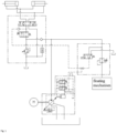
- a floating control system provided in an embodiment of the present invention includes a driving mechanism 5, a hydraulic oil tank 1, a load-sensitive variable displacement pump 2, a floating control valve 3, a floating mechanism, a boom function valve 4, an actuator, and an accumulator 8.
- the load-sensitive variable displacement pump 2 is driven by the driving mechanism 5, an oil inlet of the load-sensitive variable displacement pump 2 is connected to the hydraulic oil tank 1, an oil outlet P of the load-sensitive variable displacement pump 2 is connected to oil inlets of the floating control valve 3 and the boom function valve 4, and feedback oil ports LS of the floating control valve 3 and the boom function valve 4 are connected to a feedback oil port LS of the load-sensitive variable displacement pump 2 through feedback oil paths;
- the floating control valve 3 is connected to the accumulator 8, the floating mechanism, and the hydraulic oil tank 1; and the boom function valve 4 is connected to the actuator and the hydraulic oil tank 1.
- the boom function valve 4 includes a change-over switch valve 41, a change-over proportional valve 42, a third one-way valve 43, a fourth one-way valve 46, an overflow valve 45, and a two-way flow valve 44; an oil inlet of the third one-way valve 43 serves as the oil inlet P of the boom function valve 4, and an oil outlet of the third one-way valve 43 is connected to a pipeline connecting an oil inlet of the change-over proportional valve 42 and an oil inlet of the overflow valve 45; an oil outlet of the change-over proportional valve 42 is connected to a pipeline connecting an oil inlet of the fourth one-way valve 46 and an oil return port of the change-over switch valve 41, and an oil outlet of the overflow valve 45 is connected to a pipeline connecting an oil inlet of the change-over switch valve 41, the two-way flow valve 44 and the hydraulic oil tank 1; an oil outlet of the fourth one-way valve 46 serves as the feedback oil port LS of the boom function valve 4, and the two-way flow valve 44 is also connected to
- the driving mechanism 5 is a motor.
- the actuator is a change-over cylinder
- the change-over cylinder includes a left change-over cylinder 6 and a right change-over cylinder 7, and the left change-over cylinder 6 and the right change-over cylinder 7 are connected to the oil outlet of the change-over switch valve 41 respectively.
- the motor drives the load-sensitive variable displacement pump 2 to rotate, and oil from the oil outlet of the load-sensitive variable displacement pump 2 enters the floating control valve 3. Because an oil output pressure (namely, an oil pressure at the oil outlet) of the load-sensitive variable displacement pump 2 is lower than a set pressure of the logic valve 31 at this moment, the oil output pressure of the load-sensitive variable displacement pump 2 is fed back to the feedback oil port LS of the load-sensitive variable displacement pump 2 through the logic valve 31 and the feedback oil path. Because the change-over proportional valve 42 is closed, there is no feedback pressure at the feedback oil port LS of the boom function valve 4. Therefore, only the oil output pressure of the load-sensitive variable displacement pump 2 is fed back to the feedback oil port LS of the load-sensitive variable displacement pump 2.
- a flow valve on the load-sensitive variable displacement pump 2 is in a right working position due to the feedback pressure, the load-sensitive variable displacement pump 2 continues to output oil at a maximum flow rate, and the oil output pressure of the load-sensitive variable displacement pump 2 continues to increase.
- the oil output pressure of the load-sensitive variable displacement pump 2 is greater than a nitrogen charging pressure of the accumulator 8, the oil enters the accumulator 8 for energy storage, and the rate of increase in the oil output pressure decreases. After the accumulator 8 is filled with oil, the oil output pressure starts to rapidly increase again.
- the logic valve 31 changes over its direction to cut off the oil outlet of the logic valve 31, so that there is no feedback pressure at the feedback oil port LS of the load-sensitive variable displacement pump 2. At this time, the feedback oil path unloads the hydraulic oil tank 1 through the two-way flow valve 44 on the boom function valve 4.
- the flow valve on the load-sensitive variable displacement pump 2 overcomes a spring force and changes over to a left working position under the action of the oil output pressure, the oil output pressure of the load-sensitive variable displacement pump 2 enters a variable mechanism of the load-sensitive variable displacement pump 2 through the flow valve, displacement at the oil outlet of the load-sensitive variable displacement pump 2 decreases to near zero output, and the oil output pressure of the load-sensitive variable displacement pump 2 returns to a standby pressure, which is usually very low, so the power loss is very small.
- the oil in the accumulator 8 can be almost maintained at a maximum pressure before the oil outlet of the logic valve 31 is cut off, without releasing pressure.
- the accumulator 8 serves as a standby oil source for the floating mechanism, and continues to provide stable standby pressure for the floating mechanism.
- the logic valve 31 changes over its direction to open the oil outlet of the logic valve 31, and the oil output pressure of the load-sensitive variable displacement pump 2 is fed back to the feedback oil outlet LS of the load-sensitive variable displacement pump 2. Due to the feedback pressure at the feedback oil port LS of the load-sensitive variable displacement pump 2, the flow valve 21 of the load-sensitive variable displacement pump 2 changes over its direction to the right working position under the feedback pressure to break the balance maintained at the standby pressure, the variable mechanism of the load-sensitive variable displacement pump 2 restores to the maximum flow rate, and the flow rate at the oil outlet of the load-sensitive variable displacement pump 2 increases to replenish oil for the accumulator 8.
- the logic valve 31 cuts off the feedback pressure again, the feedback oil path unloads the hydraulic oil tank 1 again through the two-way flow valve 44 on the boom function valve 4, and the load-sensitive variable displacement pump 2 restores to the standby pressure state.
- the accumulator 8 provides a stable standby pressure for the floating mechanism, the load-sensitive variable displacement pump 2 operates in a standby state with extremely low power consumption, and continuous constant pressure standby of the load-sensitive variable displacement pump 2 is not required, so the power consumption is greatly reduced. Meanwhile, fully automatic floating control can be achieved by the system of the present invention, and any solenoid valve is not required to control the floating function, thereby greatly reducing hidden dangers caused by control signals, solenoid valves, and other factors and improving the reliability of the system.
- the pressure at the oil inlet of the floating control valve 3 increases, and after the pressure exceeds the nitrogen charging pressure of the accumulator 8, oil is replenished to the accumulator 8.
- the first one-way valve 32 and the pressure reducing valve 34 can directly provide pressure to the floating mechanism. After the actions stop, the oil pressure of the accumulator 8 can be continuously maintained in the presence of the first one-way valve 32 in the floating control valve 3, so as to provide a stable standby pressure for the floating mechanism.
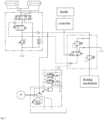
- a floating control system provided in an embodiment of the present invention includes a driving mechanism 5, a hydraulic oil tank 1, a fixed displacement pump 9, a floating control valve 3, a floating mechanism, a boom function valve 4, an actuator, and an accumulator 8.
- the fixed displacement pump 9 is driven by the driving mechanism 5, an oil inlet of the fixed displacement pump 9 is connected to the hydraulic oil tank 1, an oil outlet of the fixed displacement pump 9 is connected to oil inlets of the floating control valve 3 and the boom function valve 4, and a feedback oil port LS of the floating control valve 3 and a feedback oil port LS of the boom function valve 4 are connected through a feedback oil path;
- the floating control valve 3 is connected to the accumulator 8, the floating mechanism, and the hydraulic oil tank 1; and the boom function valve 4 is connected to the actuator and the hydraulic oil tank 1.
- the floating control valve 3 includes a first one-way valve 32, a second one-way valve 33, a pressure reducing valve 34, and a logic valve 31; an oil inlet of the first one-way valve 32 serves as the oil inlet of the floating control valve 3, an oil outlet of the first one-way valve 32 is connected to a pipeline connecting the accumulator 8, an oil inlet of the pressure reducing valve 34 and an oil inlet of the logic valve 31, an oil outlet of the logic valve 31 is connected to an oil inlet of the second one-way valve 33, an oil outlet of the second one-way valve 33 serves as the feedback oil port LS of the floating control valve 3, an oil outlet of the pressure reducing valve 34 is connected to the floating mechanism, and the pipeline connecting the pressure reducing valve 34 and the logic valve 31 is also connected to the hydraulic oil tank 1.
- the boom function valve 4 includes a change-over switch valve 41, a change-over proportional valve 42, a third one-way valve 43, a fourth one-way valve 46, an overflow valve 45, a two-way flow valve 44, and a three-way flow valve 47; an oil inlet of the third one-way valve 43 serves as the oil inlet of the boom function valve 4, and an oil outlet of the third one-way valve 43 is connected to a pipeline connecting an oil inlet of the change-over proportional valve 42, an oil inlet of the overflow valve 45 and the three-way flow valve 47; an oil outlet of the change-over proportional valve 42 is connected to a pipeline connecting an oil inlet of the fourth one-way valve 46 and an oil return port of the change-over switch valve 41, and an oil outlet of the overflow valve 45 is connected to a pipeline connecting an oil inlet of the change-over switch valve 41, the two-way flow valve 44, the three-way flow valve 47 and the hydraulic oil tank 1; an oil outlet of the fourth one-way valve 46 serves as
- the driving mechanism 5 is a motor.
- the actuator is a change-over cylinder
- the change-over cylinder includes a left change-over cylinder 6 and a right change-over cylinder 7, and the left change-over cylinder 6 and the right change-over cylinder 7 are connected to the oil outlet of the change-over switch valve 41 respectively.
- the motor drives the fixed displacement pump 9 to rotate, the oil outlet of the fixed displacement pump 9 outputs a certain flow rate of oil, and an oil output pressure of the fixed displacement pump 9 increases. Because the oil output pressure of the fixed displacement pump 9 is lower than a set pressure of the logic valve 31 at this moment, the oil output pressure of the fixed displacement pump 9 is fed back to the three-way flow valve 47 through the logic valve 31 and the feedback oil path. The three-way flow valve 47 cannot open for unloading under the actions of oil output pressure and feedback pressure, so the oil output pressure of the fixed displacement pump 9 continues to increase.
- the oil in the accumulator 8 can be almost maintained at a maximum pressure before the oil outlet of the logic valve 31 is cut off, without releasing pressure.
- the accumulator 8 serves as a standby oil source for the floating mechanism, and continues to provide stable standby pressure for the floating mechanism.
- the accumulator 8 After the energy storage in the accumulator 8 is completed, the accumulator 8 provides a stable standby pressure for the floating mechanism, the fixed displacement pump 9 operates in a standby state with extremely low power consumption, and continuous constant pressure standby of the fixed displacement pump 9 is not required, so the power consumption is greatly reduced. Meanwhile, fully automatic floating control can be achieved by the system of the present invention, and any solenoid valve is not required to control the floating function, thereby greatly reducing hidden dangers caused by control signals, solenoid valves, and other factors and improving the reliability of the system.
- the pressure at the oil inlet of the floating control valve 3 increases, and after the pressure exceeds the nitrogen charging pressure of the accumulator 8, oil is replenished to the accumulator 8.
- the first one-way valve 32 and the pressure reducing valve 34 can directly provide pressure to the floating mechanism. After the actions stop, the oil pressure of the accumulator 8 can be continuously maintained in the presence of the first one-way valve 32 in the floating control valve 3, so as to provide a stable standby pressure for the floating mechanism.
Landscapes
- Engineering & Computer Science (AREA)
- Mechanical Engineering (AREA)
- Physics & Mathematics (AREA)
- Fluid Mechanics (AREA)
- General Engineering & Computer Science (AREA)
- Structural Engineering (AREA)
- Life Sciences & Earth Sciences (AREA)
- Geology (AREA)
- Fluid-Pressure Circuits (AREA)
Applications Claiming Priority (2)
| Application Number | Priority Date | Filing Date | Title |
|---|---|---|---|
| CN202311027576.2A CN116733798B (zh) | 2023-08-16 | 2023-08-16 | 高空作业平台及其浮动控制系统 |
| PCT/CN2023/120975 WO2025035542A1 (zh) | 2023-08-16 | 2023-09-25 | 高空作业平台及其浮动控制系统 |
Publications (4)
| Publication Number | Publication Date |
|---|---|
| EP4530478A1 true EP4530478A1 (de) | 2025-04-02 |
| EP4530478A4 EP4530478A4 (de) | 2025-04-02 |
| EP4530478B1 EP4530478B1 (de) | 2025-10-29 |
| EP4530478C0 EP4530478C0 (de) | 2025-10-29 |
Family
ID=87903044
Family Applications (1)
| Application Number | Title | Priority Date | Filing Date |
|---|---|---|---|
| EP23828658.7A Active EP4530478B1 (de) | 2023-08-16 | 2023-09-25 | Hubarbeitsbühne und schwimmendes steuerungssystem dafür |
Country Status (6)
| Country | Link |
|---|---|
| US (1) | US12338109B2 (de) |
| EP (1) | EP4530478B1 (de) |
| CN (1) | CN116733798B (de) |
| AU (1) | AU2023296337B2 (de) |
| CA (1) | CA3226316A1 (de) |
| WO (1) | WO2025035542A1 (de) |
Families Citing this family (4)
| Publication number | Priority date | Publication date | Assignee | Title |
|---|---|---|---|---|
| CN115962170B (zh) * | 2022-12-19 | 2025-08-15 | 湖南星邦智能装备股份有限公司 | 一种定量泵系统浮动控制系统 |
| CN116733798B (zh) * | 2023-08-16 | 2023-11-07 | 湖南星邦智能装备股份有限公司 | 高空作业平台及其浮动控制系统 |
| CN119079912B (zh) * | 2024-10-25 | 2025-09-23 | 国网湖南省电力有限公司 | 用于横担辅助高空作业平台的举升调平系统 |
| CN121047849B (zh) * | 2025-10-31 | 2026-02-03 | 湖南山河矿岩装备有限责任公司 | 一种具备调速模式切换功能的液压系统及其工程机械 |
Family Cites Families (40)
| Publication number | Priority date | Publication date | Assignee | Title |
|---|---|---|---|---|
| CN85100042B (zh) * | 1985-04-01 | 1985-09-10 | 清华大学 | 反应堆控制棒用对孔式水力步进缸 |
| US7610988B2 (en) | 2004-02-27 | 2009-11-03 | Sauer-Danfoss Aps | Hydraulic steering |
| DE102006051894A1 (de) * | 2006-10-31 | 2008-05-08 | Deere & Company, Moline | Federungssystem |
| CN102155444A (zh) * | 2011-03-08 | 2011-08-17 | 太原理工大学 | 一种煤矿自动排水系统用液动执行器 |
| CN102182715B (zh) * | 2011-05-20 | 2012-11-14 | 中联重科股份有限公司 | 液压控制系统及其液压控制模块及具有该系统的工程机械 |
| CN103047210B (zh) * | 2012-12-29 | 2016-04-13 | 潍坊威度电子科技有限公司 | 液压分配器的电液操控装置 |
| CN103277355B (zh) * | 2013-06-21 | 2016-01-20 | 徐州重型机械有限公司 | 登高平台消防车及其液压调平系统 |
| CN103438037B (zh) * | 2013-08-06 | 2016-03-23 | 湖南星邦重工有限公司 | 一种剪叉式高空作业车平台举升和下降动作液压系统 |
| CN103644155B (zh) * | 2013-12-17 | 2016-01-13 | 上海电气电站设备有限公司 | 一种液压执行机构 |
| CN103742344B (zh) * | 2013-12-23 | 2016-01-27 | 浙江大学 | 基于液压传动的多轴点吸收式波浪能发电装置 |
| CN103939403A (zh) * | 2014-04-29 | 2014-07-23 | 三一重通机械有限公司 | 一种负载敏感液压系统及推土机 |
| CN104386616A (zh) * | 2014-09-18 | 2015-03-04 | 芜湖高昌液压机电技术有限公司 | 剪式举升机卸荷溢流阀卸荷回路 |
| CN105605000A (zh) * | 2014-11-22 | 2016-05-25 | 西安志越机电科技有限公司 | 高空作业平台伸缩臂调整用液压驱动回路 |
| CN104632729B (zh) * | 2015-02-05 | 2017-02-22 | 长安大学 | 一种旋挖钻机主卷扬液压系统 |
| CN104595292A (zh) * | 2015-02-05 | 2015-05-06 | 长安大学 | 一种基于蓄能器能量回收的旋挖钻机主卷扬系统 |
| CN105415731B (zh) * | 2015-12-23 | 2017-06-16 | 华中科技大学 | 一种适用于水液压压铸机的液压系统 |
| CN107055418A (zh) * | 2017-04-20 | 2017-08-18 | 湖南美奕机电科技有限公司 | 一种高空作业车及其液压调平系统 |
| JP6941517B2 (ja) | 2017-09-15 | 2021-09-29 | 川崎重工業株式会社 | 建設機械の油圧駆動システム |
| CN109973447B (zh) * | 2019-04-01 | 2020-08-11 | 山东临工工程机械有限公司 | 一种液压控制系统及工程机械 |
| CN210599623U (zh) * | 2019-04-10 | 2020-05-22 | 湖南星邦智能装备股份有限公司 | 一种高空作业车底架浮动油缸的控制系统及高空作业车 |
| CN111217295B (zh) * | 2020-02-25 | 2025-09-02 | 杭叉集团股份有限公司 | 一种半自动充液阀式叉车动力行车制动系统 |
| CN111637111B (zh) * | 2020-06-05 | 2022-10-25 | 徐州徐工矿业机械有限公司 | 一种超大吨位挖掘机下车张紧液压系统 |
| CN212672126U (zh) * | 2020-07-31 | 2021-03-09 | 湖南星邦智能装备股份有限公司 | 一种高空作业车及其行走底架全浮动控制系统 |
| CN212250661U (zh) * | 2020-08-03 | 2020-12-29 | 湖南星邦智能装备股份有限公司 | 一种高空作业车及其行走底架浮动油缸平衡阀控制系统 |
| CN111765136B (zh) * | 2020-08-03 | 2025-06-17 | 湖南星邦智能装备股份有限公司 | 一种高空作业车及其行走底架浮动油缸平衡阀控制系统 |
| CN213265638U (zh) * | 2020-08-24 | 2021-05-25 | 湖南星邦智能装备股份有限公司 | 一种行走液压控制系统及剪叉式高空作业平台 |
| FR3113707B1 (fr) * | 2020-08-28 | 2022-08-19 | Kuhn S A S | Circuit hydraulique pour machine agricole et machine agricole associée |
| CN113389761B (zh) * | 2021-07-20 | 2025-05-13 | 湖南星邦智能装备股份有限公司 | 一种剪叉式高空作业平台及其浮动控制系统 |
| CN215058511U (zh) * | 2021-07-20 | 2021-12-07 | 湖南星邦智能装备股份有限公司 | 一种剪叉式高空作业平台及其浮动控制系统 |
| CN113683033B (zh) * | 2021-09-23 | 2024-08-23 | 江苏柳工机械有限公司 | 臂架式高空作业平台的液压全时浮动控制系统及控制方法 |
| CN215626637U (zh) * | 2021-09-23 | 2022-01-25 | 江苏柳工机械有限公司 | 臂架式高空作业平台的液压全时浮动控制系统 |
| US12428811B2 (en) * | 2021-11-19 | 2025-09-30 | Robert Bosch Gmbh | Construction machine with active ride control |
| CN216430094U (zh) | 2021-12-21 | 2022-05-03 | 中联农业机械股份有限公司 | 一种割台的液压系统 |
| CN114776670B (zh) * | 2022-03-29 | 2024-11-29 | 江苏徐工工程机械研究院有限公司 | 一种多功能作业集成阀、控制模块、液压系统以及破拆机器人 |
| CN217783893U (zh) * | 2022-07-01 | 2022-11-11 | 融彻智能科技(上海)有限公司 | 一种动臂功能阀组 |
| CN218325528U (zh) | 2022-09-21 | 2023-01-17 | 湖南星邦智能装备股份有限公司 | 浮动机构液压控制系统以及高空作业平台 |
| CN219220885U (zh) * | 2022-11-24 | 2023-06-20 | 湖南星邦智能装备股份有限公司 | 一种高空作业车平台调平预充压系统及高空作业车平台 |
| CN115962170B (zh) * | 2022-12-19 | 2025-08-15 | 湖南星邦智能装备股份有限公司 | 一种定量泵系统浮动控制系统 |
| CN218817296U (zh) * | 2022-12-19 | 2023-04-07 | 湖南星邦智能装备股份有限公司 | 一种定量泵系统浮动控制系统 |
| CN116733798B (zh) * | 2023-08-16 | 2023-11-07 | 湖南星邦智能装备股份有限公司 | 高空作业平台及其浮动控制系统 |
-
2023
- 2023-08-16 CN CN202311027576.2A patent/CN116733798B/zh active Active
- 2023-09-25 CA CA3226316A patent/CA3226316A1/en active Pending
- 2023-09-25 AU AU2023296337A patent/AU2023296337B2/en active Active
- 2023-09-25 US US18/577,688 patent/US12338109B2/en active Active
- 2023-09-25 EP EP23828658.7A patent/EP4530478B1/de active Active
- 2023-09-25 WO PCT/CN2023/120975 patent/WO2025035542A1/zh active Pending
Also Published As
| Publication number | Publication date |
|---|---|
| CN116733798B (zh) | 2023-11-07 |
| EP4530478B1 (de) | 2025-10-29 |
| EP4530478C0 (de) | 2025-10-29 |
| US12338109B2 (en) | 2025-06-24 |
| AU2023296337A1 (en) | 2025-03-06 |
| WO2025035542A1 (zh) | 2025-02-20 |
| EP4530478A4 (de) | 2025-04-02 |
| US20250091849A1 (en) | 2025-03-20 |
| CA3226316A1 (en) | 2025-07-07 |
| CN116733798A (zh) | 2023-09-12 |
| AU2023296337B2 (en) | 2025-04-17 |
Similar Documents
| Publication | Publication Date | Title |
|---|---|---|
| EP4530478A1 (de) | Hubarbeitsbühne und schwimmendes steuerungssystem dafür | |
| CN100595440C (zh) | 基于能量调节的变频泵控马达闭式回路 | |
| CN106032261B (zh) | 大功率液压绞车的张力控制装置 | |
| CN205617466U (zh) | 多能源多电机液压挖掘机电液混合驱动系统 | |
| CN212717418U (zh) | 一种破碎机负载敏感控制液压系统 | |
| CN203834553U (zh) | 电驱动液压挖掘机的节能型转台驱动系统 | |
| WO2022227621A1 (zh) | 一种混合动力液压系统及高空作业车 | |
| CN103573729A (zh) | 矿井提升机液压站 | |
| CN109027063B (zh) | 风力发电机组的变压力偏航制动液压系统及其控制方法 | |
| CN111828411B (zh) | 基于两级供能及负载口独立阀控的液压系统和控制方法 | |
| CN220929802U (zh) | 纯电车辆的全液压系统 | |
| CN205533473U (zh) | 负载敏感反馈油路结构及负载敏感液压系统 | |
| CN116104825A (zh) | 一种零泄漏保压调速的蓄能器控制回路和控制方法 | |
| CN201116558Y (zh) | 原动机输出扭矩均衡控制装置 | |
| CN219242513U (zh) | 一种升船机制动液压系统 | |
| CN208474211U (zh) | 一种全液压制动充液阀组及其控制系统 | |
| CN111706564A (zh) | 一种基于容积变压差主动控制的二通调速阀 | |
| US20250035133A1 (en) | Floating control system for fixed displacement pump system | |
| CN217152453U (zh) | 一种基于独立负载口的克令吊回转节能液压系统 | |
| CN114776650B (zh) | 一种气液混合式快速起竖系统 | |
| CN219953790U (zh) | 一种零泄漏小流量双系统隔离阀 | |
| CN210312137U (zh) | 长距离输送机用柔性制动液压系统 | |
| CN108167237A (zh) | 工程机械的液压控制系统和挖掘机 | |
| CN214298949U (zh) | 一种海洋工程起重机液压控制阀组 | |
| CN111776157B (zh) | 小型船舶减振系统 |
Legal Events
| Date | Code | Title | Description |
|---|---|---|---|
| STAA | Information on the status of an ep patent application or granted ep patent |
Free format text: STATUS: UNKNOWN |
|
| STAA | Information on the status of an ep patent application or granted ep patent |
Free format text: STATUS: THE INTERNATIONAL PUBLICATION HAS BEEN MADE |
|
| PUAI | Public reference made under article 153(3) epc to a published international application that has entered the european phase |
Free format text: ORIGINAL CODE: 0009012 |
|
| STAA | Information on the status of an ep patent application or granted ep patent |
Free format text: STATUS: REQUEST FOR EXAMINATION WAS MADE |
|
| 17P | Request for examination filed |
Effective date: 20240104 |
|
| A4 | Supplementary search report drawn up and despatched |
Effective date: 20241113 |
|
| AK | Designated contracting states |
Kind code of ref document: A1 Designated state(s): AL AT BE BG CH CY CZ DE DK EE ES FI FR GB GR HR HU IE IS IT LI LT LU LV MC ME MK MT NL NO PL PT RO RS SE SI SK SM TR |
|
| RAP3 | Party data changed (applicant data changed or rights of an application transferred) |
Owner name: HUNAN SINOBOOM INTELLIGENT EQUIPMENT CO., LTD. |
|
| RIC1 | Information provided on ipc code assigned before grant |
Ipc: F15B 11/05 20060101ALI20250522BHEP Ipc: F15B 11/042 20060101ALI20250522BHEP Ipc: B66F 9/22 20060101ALI20250522BHEP Ipc: B66F 9/06 20060101ALI20250522BHEP Ipc: F15B 13/02 20060101ALI20250522BHEP Ipc: F15B 1/02 20060101ALI20250522BHEP Ipc: B66F 17/00 20060101ALI20250522BHEP Ipc: B66F 11/00 20060101ALI20250522BHEP Ipc: F15B 11/08 20060101AFI20250522BHEP |
|
| GRAP | Despatch of communication of intention to grant a patent |
Free format text: ORIGINAL CODE: EPIDOSNIGR1 |
|
| STAA | Information on the status of an ep patent application or granted ep patent |
Free format text: STATUS: GRANT OF PATENT IS INTENDED |
|
| DAV | Request for validation of the european patent (deleted) | ||
| DAX | Request for extension of the european patent (deleted) | ||
| INTG | Intention to grant announced |
Effective date: 20250704 |
|
| GRAS | Grant fee paid |
Free format text: ORIGINAL CODE: EPIDOSNIGR3 |
|
| GRAA | (expected) grant |
Free format text: ORIGINAL CODE: 0009210 |
|
| STAA | Information on the status of an ep patent application or granted ep patent |
Free format text: STATUS: THE PATENT HAS BEEN GRANTED |
|
| AK | Designated contracting states |
Kind code of ref document: B1 Designated state(s): AL AT BE BG CH CY CZ DE DK EE ES FI FR GB GR HR HU IE IS IT LI LT LU LV MC ME MK MT NL NO PL PT RO RS SE SI SK SM TR |
|
| REG | Reference to a national code |
Ref country code: CH Ref legal event code: F10 Free format text: ST27 STATUS EVENT CODE: U-0-0-F10-F00 (AS PROVIDED BY THE NATIONAL OFFICE) Effective date: 20251029 Ref country code: GB Ref legal event code: FG4D |
|
| REG | Reference to a national code |
Ref country code: DE Ref legal event code: R096 Ref document number: 602023008123 Country of ref document: DE |
|
| REG | Reference to a national code |
Ref country code: IE Ref legal event code: FG4D |
|
| U01 | Request for unitary effect filed |
Effective date: 20251029 |
|
| U07 | Unitary effect registered |
Designated state(s): AT BE BG DE DK EE FI FR IT LT LU LV MT NL PT RO SE SI Effective date: 20251105 |