EP4524628A2 - Faseroptischer stecker - Google Patents
Faseroptischer stecker Download PDFInfo
- Publication number
- EP4524628A2 EP4524628A2 EP25154591.9A EP25154591A EP4524628A2 EP 4524628 A2 EP4524628 A2 EP 4524628A2 EP 25154591 A EP25154591 A EP 25154591A EP 4524628 A2 EP4524628 A2 EP 4524628A2
- Authority
- EP
- European Patent Office
- Prior art keywords
- coupler
- fiber
- fiber optic
- rotatable
- ferrule
- Prior art date
- Legal status (The legal status is an assumption and is not a legal conclusion. Google has not performed a legal analysis and makes no representation as to the accuracy of the status listed.)
- Pending
Links
Images


Classifications
-
- G—PHYSICS
- G02—OPTICS
- G02B—OPTICAL ELEMENTS, SYSTEMS OR APPARATUS
- G02B6/00—Light guides; Structural details of arrangements comprising light guides and other optical elements, e.g. couplings
- G02B6/24—Coupling light guides
- G02B6/36—Mechanical coupling means
- G02B6/38—Mechanical coupling means having fibre to fibre mating means
- G02B6/3807—Dismountable connectors, i.e. comprising plugs
- G02B6/389—Dismountable connectors, i.e. comprising plugs characterised by the method of fastening connecting plugs and sockets, e.g. screw- or nut-lock, snap-in, bayonet type
- G02B6/3891—Bayonet type
-
- G—PHYSICS
- G02—OPTICS
- G02B—OPTICAL ELEMENTS, SYSTEMS OR APPARATUS
- G02B6/00—Light guides; Structural details of arrangements comprising light guides and other optical elements, e.g. couplings
- G02B6/24—Coupling light guides
- G02B6/36—Mechanical coupling means
- G02B6/38—Mechanical coupling means having fibre to fibre mating means
- G02B6/3807—Dismountable connectors, i.e. comprising plugs
- G02B6/381—Dismountable connectors, i.e. comprising plugs of the ferrule type, e.g. fibre ends embedded in ferrules, connecting a pair of fibres
- G02B6/3825—Dismountable connectors, i.e. comprising plugs of the ferrule type, e.g. fibre ends embedded in ferrules, connecting a pair of fibres with an intermediate part, e.g. adapter, receptacle, linking two plugs
-
- G—PHYSICS
- G02—OPTICS
- G02B—OPTICAL ELEMENTS, SYSTEMS OR APPARATUS
- G02B6/00—Light guides; Structural details of arrangements comprising light guides and other optical elements, e.g. couplings
- G02B6/24—Coupling light guides
- G02B6/36—Mechanical coupling means
- G02B6/38—Mechanical coupling means having fibre to fibre mating means
- G02B6/3807—Dismountable connectors, i.e. comprising plugs
- G02B6/3833—Details of mounting fibres in ferrules; Assembly methods; Manufacture
- G02B6/3866—Devices, tools or methods for cleaning connectors
-
- G—PHYSICS
- G02—OPTICS
- G02B—OPTICAL ELEMENTS, SYSTEMS OR APPARATUS
- G02B6/00—Light guides; Structural details of arrangements comprising light guides and other optical elements, e.g. couplings
- G02B6/24—Coupling light guides
- G02B6/36—Mechanical coupling means
- G02B6/38—Mechanical coupling means having fibre to fibre mating means
- G02B6/3807—Dismountable connectors, i.e. comprising plugs
- G02B6/3869—Mounting ferrules to connector body, i.e. plugs
- G02B6/3871—Ferrule rotatable with respect to plug body, e.g. for setting rotational position ; Fixation of ferrules after rotation
-
- G—PHYSICS
- G02—OPTICS
- G02B—OPTICAL ELEMENTS, SYSTEMS OR APPARATUS
- G02B6/00—Light guides; Structural details of arrangements comprising light guides and other optical elements, e.g. couplings
- G02B6/24—Coupling light guides
- G02B6/36—Mechanical coupling means
- G02B6/38—Mechanical coupling means having fibre to fibre mating means
- G02B6/3807—Dismountable connectors, i.e. comprising plugs
- G02B6/3873—Connectors using guide surfaces for aligning ferrule ends, e.g. tubes, sleeves, V-grooves, rods, pins, balls
- G02B6/3882—Connectors using guide surfaces for aligning ferrule ends, e.g. tubes, sleeves, V-grooves, rods, pins, balls using rods, pins or balls to align a pair of ferrule ends
-
- G—PHYSICS
- G02—OPTICS
- G02B—OPTICAL ELEMENTS, SYSTEMS OR APPARATUS
- G02B6/00—Light guides; Structural details of arrangements comprising light guides and other optical elements, e.g. couplings
- G02B6/24—Coupling light guides
- G02B6/36—Mechanical coupling means
- G02B6/38—Mechanical coupling means having fibre to fibre mating means
- G02B6/3807—Dismountable connectors, i.e. comprising plugs
- G02B6/3873—Connectors using guide surfaces for aligning ferrule ends, e.g. tubes, sleeves, V-grooves, rods, pins, balls
- G02B6/3885—Multicore or multichannel optical connectors, i.e. one single ferrule containing more than one fibre, e.g. ribbon type
-
- G—PHYSICS
- G02—OPTICS
- G02B—OPTICAL ELEMENTS, SYSTEMS OR APPARATUS
- G02B6/00—Light guides; Structural details of arrangements comprising light guides and other optical elements, e.g. couplings
- G02B6/44—Mechanical structures for providing tensile strength and external protection for fibres, e.g. optical transmission cables
- G02B6/4439—Auxiliary devices
- G02B6/4471—Terminating devices ; Cable clamps
- G02B6/4478—Bending relief means
Definitions
- the invention relates generally to cable connectors, and more specifically to fiber optic cable connectors having self-cleaning mechanisms and connectable to bulkhead adapters.
- Various embodiments include a fiber optic connector assembly, including a boot portion connected to a fiber optic cable, a fixed body portion connected to the boot portion, a rotatable coupler connected to the fixed body portion and configured to rotate about the fixed body portion, a ferrule connected to the rotatable coupler and configured to rotate with the rotatable coupler about the fixed body portion, and a bulkhead adapter configured to receive the rotatable coupler after the rotatable coupler has been turned in one direction and released in another direction.
- the rotatable coupler may include at least one alignment token to interface with the bulkhead adapter port and the bulkhead adapter includes at least one alignment groove to interface with the rotatable coupler.
- the bulkhead adapter port may include at least one alignment token to interface with the rotatable coupler and the rotating rotatable coupler includes at least one alignment groove to interface with the bulkhead adapter.
- the ferrule of a first fiber optic connector may include a guiding pin or a receiving gusset to connect to a ferrule of a second fiber optic connector.
- the guiding pin in the first fiber optic connector may be removable and able to be placed into a receiving gusset of a second fiber optic connector to allow for fiber optic connector gender changes.
- the bulkhead adapter may include an alignment pin insertion hole to receive a connection between a first fiber optic connector and a second fiber optic connector.
- Two alignment grooves may be placed in opposing formations on either the rotatable coupler or bulkhead adapter to support quick polarity flips.
- the ferrule may include at least one fiber plane and at least one bank of fiber strands.
- Two or four fiber planes may be positioned in a mirror configuration to support quick polarity flips.
- the ferrule face may expose at least two fiber planes multiplying the number of fiber planes and bank of fiber strands.
- a cleaning media agent may be disposed within the ferrule.
- a cleaning media agent may be disposed within the bulkhead adapter body.
- Various embodiments also include a method of providing fiber optic connectivity, including gripping a rotatable coupler of a fiber optic connector at a grip portion thereof, inserting the rotatable coupler into a bulkhead adapter in a straight direction, turning the rotatable coupler in a clockwise or counterclockwise direction to increase a tension of the spring while pushing the rotatable coupler forward, and releasing the rotatable coupler such that the rotatable coupler rotates in a counter clockwise direction and locks the fiber optic connector into the bulkhead adapter.
- the method may include releasing the rotatable coupler when the rotatable coupler has rotated in a clockwise or counterclockwise direction and reached a stop point in an alignment groove on the bulkhead adapter.
- the method may include inserting the rotatable coupler into a port of the bulkhead adapter.
- the method may include inserting an alignment token of the rotatable coupler or bulkhead adapter into an alignment groove of an adjoining bulkhead adapter or rotatable coupler.
- the method may include cleaning a front portion of the rotatable coupler when inserting the rotatable coupler into the bulkhead adapter.
- Various embodiments may also include a fiber optic connector assembly, including a boot portion connected to a fiber optic cable, a fixed body portion connected to the boot portion, a shrouded coupler connected to the fixed body portion, the shrouded coupler including a shroud disc and cleaning media agent at one end thereof, a ferrule connected to the rotatable coupler and configured to couple to the shroud disc of the shrouded coupler, and a bulkhead adapter configured to receive the shrouded coupler and provide connection for a fiber optic cable.
- a fiber optic connector assembly including a boot portion connected to a fiber optic cable, a fixed body portion connected to the boot portion, a shrouded coupler connected to the fixed body portion, the shrouded coupler including a shroud disc and cleaning media agent at one end thereof, a ferrule connected to the rotatable coupler and configured to couple to the shroud disc of the shrouded coupler, and a bulkhead adapter configured to receive the shrouded
- the shrouded coupler may include a guiding pin extending through a ferrule face of the ferrule and the shrouded coupler extends and covers the guiding pin, ferrule face, and ferrule.
- the shroud disc may be removable from the shrouded coupler.
- the shrouded coupler may include a rotatable coupler region that rotates about a fixed ferrule to move the ferrule towards the cleaning media.
- the shrouded coupler may include a coupler region and a rotatable ferrule that is configured to rotate inside the coupler region towards the cleaning media.
- the ferrule may have a cylindrical shape to extend out of the shrouded coupler to interface with the shroud disc.
- the shroud disc may include cutout gaps to receive banks of fiber strands within the ferrule.
- the alignment token tracks/grooves 161 or 163 accept the first and second alignment tokens 162 and 164, then guide the rotatable coupler 130 through the alignment token track/groove 161 and 163.
- the tracks/grooves allow a user to rotate the rotatable coupler 130 as it is inserted, and securing the fiber optics connector 100 into its final alignment position within the bulkhead adapter 150.
- This twist-and-return action of the rotatable couplers 130 and 230 allow for fastening the fiber optics connectors 100 and 200 by pushing them in, and letting the tracks/grooves guide the rotation of the rotatable couplers 130 and 230.
- the releasing aspect is performed through another twist of the rotatable couplers 130 and 230 without having to place a user's fingers close to the adjoining circular ferrule 135 or bulkhead adapters 150 or 250.
- the alignment tokens are placed on the rotatable couplers 130 or 230, or in the bulkhead adapters 150 or 250, the insertion movement of the rotatable couplers 130 or 230 into the bulkhead adapters is the same 150 or 250.
- the twist-and-return action, in combination with the embedded cleaning media agent 145 may also perform a self-cleaning function of wiping an opposing fiber plane 140 and fiber strand surface, prior to the final mating alignment and mating of the fiber strands together.
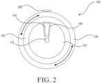
- FIG. 2 illustrates a front view of the fiber optic connector 100 and circular ferrule 135 in accordance with FIG. 1 .
- the circular ferrule 135 may be affixed to the rotatable coupler 130 and rotate along with the rotatable coupler 130 during the twist-and return fasten and release action.
- a front portion of the circular ferrule 135 is the ferrule face 137.
- the ferrule 135 and ferrule face 137 may be shaped to specifically host components that pass through and are part of the ferrule 135 and such as an embedded trapezoid sector or other shaped fiber planes 140, radial bank(s) of fiber strands 143, and the cleaning media agent 145 (illustrated in FIG. 1 ).
- the fiber planes 140 having bank(s) of fiber strands 143 are not limited to a trapezoid sector shape, but may use other configurations in which to connect fiber strands of mating connectors.
- the fiber planes 140 may be oval, rectangular, square, triangular, or other polygon shape that may enclose a single or group of fiber stands.
- a layout of the cleaning media agent 145 may be shaped in a similar manner to the fiber planes so that the cleaning media agents 145 is able to adequately wipe the fiber strands.
- the ferrule face 137 of the ferrule 135 may match and mate to an adjoining/opposing fiber optics connector (not illustrated) to complete fiber optics connectivity.
- a center guide pin 172 may be used to connect one fiber optic connector 100 to another and provide additional communication ability.
- a center placement of the center guide pin 172 allows for rotational functionality during fastening and release of the fiber optic connector 100 and also provides precise axial alignment of the fiber planes 140 and fiber strand banks 143 when mated.
- FIG. 3 illustrates a mating connection of fiber optic cable connectors 102 and 104 through the bulkhead adapter 150 in accordance with FIG. 1 .
- the bulkhead adapter port 151 may take the form of a sleeve or shroud that accepts the fiber optic connector 100 and also hosts the embedded alignment track/grooves 161 and 163 or mating alignment tokens 262 or 264 depending on the design in use.
- the bulkhead adapter 150 may have bulkhead mating planes 165 within opposing bulkhead adapter ports 151.
- the bulkhead mating planes 165 may be disposed on both sides of a body portion 149 of the bulkhead adapter 150.
- ferrules 135 of the opposing fiber optic connectors 102 and 104 When mounted within the bulkhead adapter port 151, ferrules 135 of the opposing fiber optic connectors 102 and 104 mate through the mating planes 165 within the body portion 149. Opposing ferrules 135 rest against and align two conjoining/mated fiber planes 140 and bank(s) of fiber strands 143 of opposing fiber optic connectors 102 and 104 to make a fiber optic cable connection.
- a cleaning media agent 145 in a first ferrule of the first fiber optic connector 102 may rotate against an opposing ferrule of the second fiber optic connector 104, wiping and cleaning the tips of the fiber strands of the second fiber optic connector 104. Alternativley, or simultaneously, the cleanring media agent 145 of the second fiber optic connector 104 may clean the fiber strands of the first fiber optic connector 102.
- the bulkhead mating planes 165 or the body portion 149 may be fiber alignment planes where the banks of fiber strands 143 are contained and aligned.
- the bulkhead port 151 may include a receiving cavity 175 to accept the fiber optic connector 100 and which contains the mating plane 165.
- the bulkhead adapter 150 may also include its own cleaning wiping area where the body portion 149 can host the fiber cleaning media used to swipe or wipe the fiber planes 140 of the fiber optic connectors 102 and 104 during the twist-and-return fasten and release of the fiber optic connectors 102 and 104 to the bulkhead adapter 150.
- the bulkhead adapter 150 may further include a panel clip or mounting screw (not illustrated) embodded in the body portion 149 that is used to affix and secure the bulkhead adapter 150 onto an infrastructure path panel or transceiver.
- the bulkhead adapter 150 furth includes an alignment pin insertion hole 174 within the body portion 149 and bulkhead mating plane 165 to accept the center guide pin 172 of an inserted fiber optic connector 102.
- the center guide pin 172 is passed through the mating plane 165 and body portion 149 to be inserted into a gusset 139 of a conjoining female fiber optics connector 104.
- the alignment pin insertion hole 174 may be of a specific diameter that specifically accepts the center guide pin 172, allowing for rotation of the fiber optic connector 102 and helping to achieve optimal alignment and connectivity performance.
- the diameter may be similar in diameter and length to the gusset 139, such as 1.5 - 2.0mm in diameter, and 15mm in length. (rec. 1.5 - 2mm diameter, length 15mm).
- the male fiber optics connector 102 is positioned to be coupled to the female fiber optics connector 104.
- the male fiber optics connector 102 has the male center guide pin 172 disposed into a center of the circular ferrule 135A.
- the female fiber optics connector 104 has the receiving gusset 139 to receive the center guide pin 172 and complete a coupling of the two connectors 102 and 104.
- the gusset 139 is disposed on the circular ferrule 135B and rotatable coupler 330B.
- the receiving gusset 139 may be of a specific diameter that specifically accepts the center guide pin 172, allowing for the rotation of the rotatable coupler 330A as it is inserted into the bulkhead adapter port 151 of the bulkhead adapter 150.
- the receiving gusset 139 of a receiving female fiber optic connector 104 helps to achieve optimal alignment and connectivity performance.
- the diameter of the receiving gusset 139 may be similarly sized to the center guide pin 172, on the order of, but slightly larger than 1.5 to 2.0mm in diameter having a length of about 15mm.
- the receiving gusset 139 may be conductive to complete connectivity with the mated center guide pin 172 providing an additional or supplementary source of connectivity within the connector in addition to the fiber optic strands.
- the fiber optic connectors 100 described herein have multimedia capabilities.
- the fiber optic connectors 100 have an additional feature, where the center guide pin 172 or multiple fiber plane 140 design can be made of or used to contain a separate connectivity media type such as copper, a variation of fiber optics or other media, to grant the connector the capability of supporting multimedia connectivity within a single connection.
- the center guide pin 172 can be used to support copper cabling connectivity as it inserts directly into the gusset 139 of another mated fiber optics connector 100.
- each individual fiber plane 140 can host a separate and different embedded media type in parallel to the primary fiber plane and embedded bank(s) of fiber strands 143.
- the circular and round shape of the ferrule face 137 provides several beneficial attributes such as providing a large mating surface area to provide good space efficiency per fiber strand.
- the circular ferrule 135 houses at least one sector shaped fiber plane 140 that have parallel and opposing formations in opposing fiber optic connectors which provide easy "on the fly” polarity adjustments/flips.
- the circular ferrule 135 allows for twist-and-return action of the rotatable coupler 130 for spaceless fastening and releasing of the fiber optics connector 100 from the bulkhead adapter 150.
- FIG. 4 illustrates another mating connection of fiber optic cable connectors 202 and 204 thorugh another bulkhead adapter 250 in accordance with FIG. 1 .
- an alignment groove 261A may be disposed in a rotatable coupler 230A of a fiber optic connector 202 and a second alignment groove 261B may be disposed in a rotatable coupler 230B of a fiber optic connector 204.
- the rotatable coupler 230A may rotate about an alignment pin 262A disposed in a bulkhead adapter port 251A.
- the rotatable coupler 230B may rotate about an alignment pin 262B in a bulkhead adapter port 251B.
- Other common features previously described with reference to FIGS. 1 , 2 , and 3 also apply to the embodiment of FIG. 4 , including but not limited to the cleaning media placement in the ferrules or body portion.
- rows I and II may denote an uncoupled stage of the fiber optic connector 100 and the bulkhead adapter 151, and an uncoupled position of the fiber optic connector 200 and the bulkhead adapter port 251.
- the alignment token track/grooves 161, 163, 261, and 263 may be configured to have an initial straight portion (along an axis "Z") that is disposed perpendicular to a cross-section of respective bulkhead adapter port 151 perimeter.
- the fiber optic connector 100 may be initially coupled to the bulkhead adapter port 151.
- the fiber optic connector 200 may be initially coupled to the bulkhead adapter port 251.
- the alignment token track/grooves 161, 163, 261, and 263 include a diagonal portion for further insertion of the fiber optics connectors 100 and 200.
- the diagonal portions guide a turning motion of the rotatable couplers 130 and 230 within the respective bulkhead adapter ports 151 and 251.
- stage “D” to achieve a locking or fully mounted configuration in the first and/or second alignment token track/grooves 161 or 163, and/or 261 and 263, the alignment tracks may conclude with a straight portion (along axis "X") that is parallel to the cross-section of the bulkhead adapter port 151 and 251 perimeters.
- Spring tension in the rotatable couplers 130 or 230 may increase in row “C” as the rotatable couplers 130 or 230 are rotated along the diagonal path.
- the rotatable couplers 130 or 230 may become securely held within the bulkhead adapter ports 151 or 251, biased by internal springs of the rotatable couplers 130 or 230.
- the circular ferrules 135 may accept multiple possible arrangements for banks of fiber optic strands.
- Fiber strands may be in a fiber bank 143 having the shape of a trapezoid, referred to as a sector. This sector enables a wider portion of the trapezoid to align with an arc of the circular ferrule 135 and a narrow portion of the trapezoid to match with a narrower arc on along the center guide pin 172 or receiving gusset 139.
- the trapezoid sector shape may permit a precise alignment of banks of fiber strands 143 when mated, and at a higher quantity of fiber strands versus conventional flat row formats.
- the fiber plane 140 is a designated area on the ferrule face 137 where bank(s) of fiber strands 143 are contained and aligned. More than one fiber bank 140 may be provided within a fiber optic connector 100.
- the fiber plane 140 is also a targeted area of media cleaning/wiping.
- the fiber plane 140 is the area on the ferrule face 137 that is used to house the embedded bank(s) of fiber strands 143.
- the trapezoid sector shape allows for radial or flat formation/orientation of bank(s) of fiber strands 143 providing greater precision in fiber strand alignments between mated fiber optic connectors 100.
- the trapezoid shape of the fiber plane 140 allows for the cleaning/wiping of media 145 used to wipe an opposing surface of the fiber plane 140 and embedded bank(s) of fiber strands 143, during the twist-and-release movement of the fiber optics connectors 100.
- the fiber planes 140 can be positioned on the circular ferrule 135 in parallel, diametric, and quad orientations to mirror fiber strand formations, allowing for easy polarity changes or flips without the need to modify or remove the rotatable coupler 130.
- a bank of fiber strands 143 is a grouping and formation within the fiber plane 140.
- the bank of fiber strands 143 are precisely aligned to mate and marry to an adjoining fiber optic connector 100 in order to complete fiber optics connectivity of two or more cables connected together, and/or cables to a patch panel, source, or destination panel.
- the circular ferrule face 137 has a large mating surface area to connector body ratio.
- Embodiments described herein include high fiber strand count at low loss. The result is higher fiber optics connectivity performance (>.03db) at quantities exceeding 48 strands. Superior fiber alignment performance is enabled having very high strand counts to provide a significant increase in both fiber strand quantity and density per connector.
- FIGS. 5A-5C illustrate example fiber banks and fiber optic strand formations in accordance with embodiments described herein.
- FIG. 5A illustrates different variations of a duplex and quad small form-factor pluggable (QSFP) fiber connector 510 in accordance with embodiments described herein.
- QSFP quad small form-factor pluggable
- a first group 512 represents different configurations of a one strand fiber orientation that may be used according to embodiments described herein. Each strand may include numerous smaller strands embedded therein.
- a second group 514 represents different configurations of a two strand fiber orientation that may be used according to embodiments described herein.
- a third group 516 represents different configurations of a four strand fiber orientation that may be used according to embodiments described herein.
- a fourth group 518 represents different configurations of an eight strand fiber orientation that may be used according to embodiments described herein.
- One skilled in the art may be able to determine alternative arrangements for the one, two, four, and eight strange fiber orientations without deviating from the spirit of the implementations presented herein, given the trapezoidal shape of the disclosed fiber sectors.
- FIG. 5B illustrates different fiber strand orientations of a high density fiber connector 520 in accordance with embodiments described herein.
- the high density fiber connector 520 may include various configurations for a twelve strand fiber orientation. Particular arrangements are not limited thereto.
- One skilled in the art may be able to determine alternative arrangements for the twelve strange fiber orientations without deviating from the spirit of the implementations presented herein, given the trapezoidal shape of the disclosed fiber sectors.
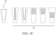
- FIG. 5C illustrates different fiber strand orientations of a super high density fiber connector 530 in accordance with embodiments described herein.
- the super high density fiber 530 may include various configurations for a twenty-four strand fiber orientation. Particular arrangements are not limited thereto. One skilled in the art may be able to determine alternative arrangements for the twenty-four strange fiber orientations without deviating from the spirit of the implementations presented herein, given the trapezoidal shape of the disclosed fiber sectors.
- the fiber planes 140 and banks of fiber strands 143 may be cleaned as described herein.
- the circular ferrule 135 may further house the cleaning media agent 145 used to wipe the surface of the fiber planes 140 and embedded banks of fiber strands 143, during fastening and release of the fiber optics connector 100 to the bulkhead adapter 150.
- a cleaning media may be used in the circular ferrules 135 to swipe or wipe the fiber plane(s) 140 and bank(s) of opposing fiber strands 143 of an opposing fiber optics connector during a twist-and-return fasten and release process of the fiber optics connector 100 to the bulkhead adapter 150, ensuring a clean and debris free connection between two connector interfaces.
- the circular ferrule 135 may include injection port holes (not illustrated) for injecting a liquid or semi-solid cleaning media agent 145 that can saturate a wiping media of the fiber plane 140 which may aid in cleaning debris off of the fiber plane 140 and bank(s) of fiber strands 143.
- the injection port holes may also be used as a push through to remove the wiping media so it can be replaced.
- Tools and detergents can be implemented to cleanse the cleaning media agent 145 on the fiber optics connector 100 or bulkhead adapter 150, ensuring that residual debris may not end up causing cross contamination if the fiber optics connectors 100 are frequently connected or disconnected.
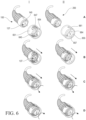
- FIG. 6 illustrates use of a thin cleaning media agent 645 on a bulkhead adapter port 651 in accordance with embodiments described herein.
- a thin cleaning media agent 645 may be disposed on an end face 654 of the bulkhead adapter port 651.
- a thin cleaning media agent 655 may be disposed on an end face 664 of the bulkhead adapter port 661.
- the cleaning media agents 645 and 655 are sufficiently thin so the ferrule faces of both connectors can be placed in close proximity such that their adjoining fiber plane and fiber strands can complete optical connectivity.
- the shape of the cleaning media agents 645 and 655 on the end face 664 may be configured to support a complete wiping and cleaning of the ferrule face during the rotate and return action of the connector's insertion or release.
- the cutout gaps 647 and 657 utilize the remaining space of the end face 664 and may be shaped to fit the ferrule faces 137 and fiber banks 140.
- the cutout gaps 647 and 657 are thus shaped so that fiber planes 140 may extend through the cutout gaps to expose the cleaned tips of the fiber strands to mate with fiber strands of an opposing connector within the bulkhead adapter.
- a fiber optic connector 100 may be loaded into the bulkhead adapter port 651 in a similar manner to the mounting a rotation described regarding FIG. 1 .
- Row “A” illustrates an uncoupled stage.
- Row “B” illustrates a first coupling stage.
- row “C” during a rotation stage along the diagonal portion of the alignment track(s)/groove(s), the fiber plane 140 is moved closer to the cleaning media agent 645 of the bulkhead adapter port 651. At the end of the diagonal alignment groove, the fiber plane 140 has been fully rotated and pushed forward to be flush with the cleaning media agent 645.
- the cleaning agent 545 brushes against the bank(s) of fiber strands 143 that are exposed in the fiber planes 140, attracting and extracting dirt and debris as the cleaning media agent 545 wipes the surface of the fiber plane 140. This action of wiping the fiber plane 140 occurs whether there are one, two, four, or more fiber planes exposed on a ferrule face, in accordance with embodiments described herein.
- Embodiments described herein provide for flexible fiber strand orientation flips and quick polarity changes.
- the design of the fiber optic connector 100 described herein has the ability to flip or reverse polarity of banks of fiber strand 143 sequencing/formations, without the need to disassemble or modify the fiber optic connector 100 or its components. This is performed by simply inserting the fiber optic connector 100 upside-down or right-side up into the bulkhead adapter 150.
- the inverted insertion capability is made possible by the alignment tokens 162, 164, 262, and 264 and/or the alignment track/grooves 161, 163, 261, and 263 placement on opposing sides of the rotatable coupler 130 and bulkhead adapter 150, which can accept the fiber optic connector 100 being inserted either orientation.
- FIGS. 7A and 7B illustrate multiple fiber bank configurations embedded in the fiber optic connector in accordance with embodiments described herein.
- multiple fiber banks of fiber strands may be used in a single connector.
- FIG. 7A illustrates a scenario in which twenty-four to forty-eight fiber strands may be used.
- First and second banks of fiber strands 743A and 743B may be used to increase a quantity of connectivity of a fiber optic connector 100.
- the fiber optic connector of FIG. 7A may thus have a mirrored fiber plane layout.
- Both banks of fiber strands 743A and 743B have the sector trapezoidal shape, maximizing the space within the circular ferrule face 137.
- a first fiber bank FIG. 7A illustrates the use a single alignment token 162, but embodiments are not limited thereto.
- a second alignment token could be used to increase the connectivity of the fiber optic connector 100.
- FIG. 7B illustrates a scenario in which forty-eight to ninety-six fiber strands may be used in a mirrored layout of four banks of fiber planes 743C, 743D, 743E, and 743F.
- the circular ferrule faces 137 with the mirrored fiber plane layout orientation allows for easy polarity changes/flips without the need to modify or remove the connector housing, achieved by simply inserting the fiber optic connector 100 upside down or right-side up into a bulkhead adapter (not illustrated).
- 6B further illustrates and includes the cleaning media agent 145 disposed between the fiber planes 140.
- FIG. 8 illustrates a smaller form factor fiber optic connector 800 in accordance with FIG. 4A.
- any of the banks of fiber strands illustrated in FIGS. 4B, or 4C may be used.
- a smaller fiber optic connectors such as the one illustrated in FIG. 8 with smaller ferrules and smaller ferrule faces may be used accordingly.
- embodiments described herein include a compatible bulkhead adapter to support the smaller form factor fiber optic connectors and ferrules.
- the smaller form factor illustrated in FIG. 8 may host duplex and Quad Small Form-factor Pluggable (QFSP) fiber formations.
- a larger form factor connector 700 illustrated in FIGS. 7A and 7B may host high density and super high density fiber formation.
- QFSP Quad Small Form-factor Pluggable
- a method of operation of the fiber optic connectors 100 described herein may be described with reference to the illustrated figures.
- FIG. 1 , column I, and FIG. 2 when a user desires to connect fiber planes 140 on a male fiber optic connector 102 to a female fiber optic connector 104, several steps may be undertaken. There is no designated order of connection.
- a male 102 or female 104 fiber optic connector may be connected first or second.
- On the side of the male fiber optic connector 102 a user may grab onto the connecting grip portion 132 of the male fiber optic connector 102. If a single alignment token 162 is present on the male fiber optic connector 102, the user may align the alignment token 162 with the alignment track/groove 161.
- the user To begin coupling the male fiber optic connector 102 to the bulkhead adapter 150, the user must push the rotatable coupler 130 forward into the initial straight portion of the alignment track/groove 161 on the bulkhead adapter port 151 of the bulkhead adapter 150.
- the second portion of the alignment track/groove 161 may force the user to rotate the rotatable coupler 130 in a clockwise or counterclockwise direction, depending on an orientation of the alignment track groove 161.
- the fiber optic cable 105, boot portion 110, and fixed body portion 120 may not rotate.
- the rotatable coupler 130 may begin to rotate preloaded by an internal spring mechanism, where preload tension of the spring increases as the degree of rotation increases.
- the user may release the tension on the spring, and the alignment token 162 may move along the final straight portion of the alignment track groove 161 to come to rest position within the bulkhead adapter port 151 of the bulkhead adapter 150.
- This movement is referred to herein as the fasten-and-release mechanism, or twist-and-release movement.
- the configuration and movement succeeds in firmly loading and holding a fiber optic connector 100 into a bulkhead adapter port, such that fiber planes 140 of fiber optic connectors 100 may be properly aligned for mating and signal communication.
- the fiber planes 140 and bank(s) of fiber strands 143 may be cleaned as the fiber optic connector 100 is being mounted.
- the insertion movements may be reversed including compressing and release of the internal spring mechanisms to de-couple a fiber optic connector 100 from a bulkhead adapter 150.
- more than one alignment token and alignment groove may be used to provide additional security to the system.
- the rotatable coupler 130 may include alignment grooves while the bulkhead adapter port includes the alignment tokens, as illustrated in column II of FIG. 1 , and a similar mounting method may be performed.
- Embodiments described herein thus provide a high density fiber strand and low loss connectivity solutions.
- the culmination of unique fiber optic connector 100 components including but not limited to a large circular ferrule, sector shaped fiber planes, radial banks of fiber strands, a center guide pin and gusset, alignment tokens, and tracks/grooves, results in a precise alignment of fiber strands when fiber optic connectors 100 are mated, and at a higher quantity of fiber strands.
- the result is higher fiber optics connectivity performance (>.03db) at fiber strand quantities up to and exceeding forty-eight fiber strands.
- the fiber optic connectors 100 having a circular and cylindrical shape and a rotatable couplers, allows for the "twist-and-return" action described herein for fastening and releasing the fiber optic connectors from a bulkhead adapter port.
- This feature has the added benefit of allowing handling of the fiber optic connectors to be performed away from a connector head or bulkhead adapter port, reducing the overall footprint of the fiber optic connector and allowing for a tighter grouping and higher population of ports per patch panel.
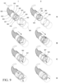
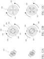
- FIGS. 9 and 10A - 10C illustrate rotatable shroud couplers 930 having fixed circular ferrules 935 in accordance with embodiments described herein.
- the rotatable shroud coupler 930 is a variation of the rotatable coupler 130 described previously.
- the rotatable shroud coupler 930 includes an elongated covering and provides protection to the circular ferrule 935, ferrule face 937, fiber planes 940 and the center guiding pin 972.
- the circular ferrule 935 includes a cylindrical shape and protrudes out of the rotatabe shroud coupler 930 when the rotatable shroud coupler 930 is inserted into the bulkhead 950.
- the rotatable shroud coupler 930 further includes a shroud disc 944 at one end thereof that can host a cleaning media 945.
- the shroud disc 944 of rotatable shroud coupler 930 the includes the cleaning media 945 adjacent cutout gaps 947 in which to receive the bank(s) of fiber strands extending through the ferrule face 937 after they are wiped and cleaned.
- the shroud disc 944 of the rotatable shroud coupler 930 is disposed on an end of the rotatable shroud coupler 930 opposite the connecting grip 932.
- the shroud disc 944 is removable from the rotatable shroud coupler 930 for general maintenance, repair or replacement.
- stages A through D Different stages of insertion of rotatable shroud couplers are illustrated in column I and II, stages A through D. As illustrated in column I, and transitioning from stage A to stage D, a fiber optic cable 105 connected to the rotatable shroud coupler 930 is inserted into the bulkhead adapter 950.
- the stages A to D are not rigid demarcation points. The depictions and descriptions of these stages A to D are meant to represent a continuous movement of parts, from an initial insertion, cleaning, to a secure connection.
- a counter-clockwise turn 1060 may engage the rotatable shroud coupler 930 to a bulkhead 950, and a counter-clockwise turn 1050 may release the rotatable shroud coupler 930.
- Orientations of the alignment tracks and rotation of the rotatable shroud coupler 930 may be mirrored to provide opposite rotations thereof.
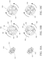
- FIGS. 11 and 12A-12C illustrate fixed shroud couplers 1130 and rotating circular ferrules 1135 in accordance with embodiments described herein.
- the fixed shroud coupler 1130 includes a base portion adjacent the connecting grip 1132 and an extending shroud portion that covers the circular ferrule 1135. Upon rotation of the circular ferrule 1135, the circular ferrule 1135 may protrude out of the base portion of the shroud coupler and within the extended portion of the fixed shroud coupler for it to be cleaned and put into a mating position.
- the fixed shroud coupler 1130 provides protection to the front ferrule face 137, fiber planes 140 and the center guiding pin 172.
- the fixed shroud coupler 1130 further includes a shroud disc 1144 having cleaning media 1145 formed integrally within the shroud disc 1144.
- the shroud disc 1144 includes cutout gaps adjacent the cleaning media.
- the shroud disc 1144 of the fixed shroud coupler 1130 is disposed on an end of the fixed shroud coupler 1130 opposite the connecting grip 1132.
- the shroud disc 1144 is removable from the fixed shroud coupler 1130 for general maintenance, repair or replacement.
- the shroud disc 1144 of the fixed shroud coupler 1130 the includes the cleaning media 1145 adjacent cutout gaps 1147 in which to receive the bank(s) of fiber strands extending through the ferrule face of the ferrule 1135 after they are wiped and cleaned.
- the fixed shroud coupler 1130 may have an alignment token 1162 disposed thereon to be received within a track or groove 1161 of a bulkhead adapter 1150. Illustrated in FIG. 11 are two sides 1150 and 1160 of a bulkhead adapter in accordance with embodiments described herein.
- the track or groove 1161 may have varying shapes as described herein.
- a fiber optic cable 105 connected to the fixed shroud coupler 1130 is inserted into the bulkhead adapter 150.
- the stages A to D are not rigid demarcation points, but represent different snapshots of the movement of the parts described and illustrated herein.
- an initial coupling takes place.
- the shroud coupler 1130 is inserted into the bulkhead adapter 1150 and the alignment token 1162 is inserted into a first straight portion of the track 1161.
- the circular ferrule 1135 does not yet rotate as the circular ferrule 1135 body is pushed through the shroud coupler 1130 until it mates with the cleaning media 1145.
- the orientation of the shroud coupler 1130 does not rotate.
- the fiber plane(s) 1140 within the circular ferrule 1135 do rotate.
- stage D Upon further insertion by a user from stage C to stage D, instead of the fixed shroud coupler 1130 rotating in the bulkhead 1150, it is the circular ferrule 1135 that rotates against the fixed cleaning media 1145 as the fixed shroud coupler 1130 is pushed into the bulkhead adapter 1150.
- the circular ferrule 1135 rotates and the shroud coupler 1130 with cleaning media 1145 remains fixed in place.
- the rotation of the ferrule face 1137 wipes the bank(s) fiber strands against the cleaning media, effectuating cleaning and disinfecting as described herein.
- the pushing and rotation movement of the cylindrical and circular ferrule 1135 effectuates the cleaning action of the cleaning media 1145.
- FIG. 11 illustrates another embodiment of a fixed shroud coupler 1132 and rotating circular ferrule 1135 in which a second alignment groove track 1163 is disposed on the fixed shroud coupler 1132 and an alignment pin 1164 is affixed to the bulkhead adapter 1150.
- the groove 1163 is inserted over the alignment pin 1164.
- Further insertion and rotation of the circular ferrule 1135 then mimics the embodiment of column I in which the circular ferrule 1135 is rotated against the cleaning media 1145 to clean the bank(s) fiber strands.
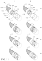
- FIGS. 12A - 12C illustrates front views of various fixed shroud couplers in accordance with FIG. 11 . Multiple form factors may be used.
- FIG. 12A illustrates a duplex or QFSP cable S body connector 1210 which may utilize one to four fiber strands per fiber bank for a total capacity of two to eight fiber strands.
- FIG. 12B illustrates a high density (HD) version of the cable connector in a larger "L" body format 1220 that includes two opposing fiber banks 1240 and 1241 each hosting 12-24 fiber strands for a total capacity of up to 48 strands per connector.
- the upper position of FIG. 12B denotes a starting or ending point of rotation of the ferrule face as opposed to the shroud disc 1244.
- the lower position of FIG. 12B denotes a rotated position of the ferrule face and shroud disc 1244 when completely inserted into the bulkhead adapter 1150.
- FIG. 12C illustrates a super high density (SHD) version of the cable connector which also utilizes the larger "L" body format 1230.
- the SHD cable connector 1230 adds an additional two fiber planes 1251 and 1252 to the embodiment of FIG. 12B . each plane hosting 12-24 fiber strands for a total capacity of up to 96 strands per connector.
- FIGS. 12A - 12C have similar components that will be described with reference to FIG. 12B .
- Each of the embodiments include a rotatable ferrule region 1235 and a cleaning/wiping media area 1245.
- the cleaning/wiping media area 1245 is in the shape of a cross, having four legs, but is not limited thereto.
- the cleaning/wiping media area may take the form of any polygon or shape in which to adequately wipe the bank(s) of fiber strands exposed via a ferrule face. These polygonal shapes are separated by cutout gap regions 1247 in which to receive the cleaned bank(s) of fiber strands.
- the rotatable cylindrical and circular ferrule 1135 provides a ferrule face 1137 exposing bank(s) of fiber planes 1140.
- the rotatable circular ferrule 1135 rotates against the cleaning media area 1245 to wipe the fiber strands over the cleaning media, and the fixed shroud coupler 1130 remains fixed in place.
- the pushing and rotating action then secures the rotatable circular ferrule 1135 within the cutout gaps 1247 of the removable shroud disc 1244, where the clean fiber strands are ready for mating with an opposing cable connector.
- the cleaning/wiping media area 1245 is connected to an outer rim of a removable shroud disc 1244.
- a counter-clockwise turn 1260 may engage the rotatable ferrule 1235 to a bulkhead 1150 triggering the wiping of the fiber strands, and a clockwise turn 1250 may release the rotatable ferrule 1235.
Landscapes
- Physics & Mathematics (AREA)
- General Physics & Mathematics (AREA)
- Optics & Photonics (AREA)
- Mechanical Coupling Of Light Guides (AREA)
Applications Claiming Priority (3)
| Application Number | Priority Date | Filing Date | Title |
|---|---|---|---|
| US15/881,110 US10422965B2 (en) | 2018-01-26 | 2018-01-26 | Fiber optic connector |
| EP19743530.8A EP3743752B1 (de) | 2018-01-26 | 2019-01-23 | Faseroptischer verbinder |
| PCT/US2019/014812 WO2019147716A2 (en) | 2018-01-26 | 2019-01-23 | Fiber optic connector |
Related Parent Applications (1)
| Application Number | Title | Priority Date | Filing Date |
|---|---|---|---|
| EP19743530.8A Division EP3743752B1 (de) | 2018-01-26 | 2019-01-23 | Faseroptischer verbinder |
Publications (2)
| Publication Number | Publication Date |
|---|---|
| EP4524628A2 true EP4524628A2 (de) | 2025-03-19 |
| EP4524628A3 EP4524628A3 (de) | 2025-08-27 |
Family
ID=67391449
Family Applications (2)
| Application Number | Title | Priority Date | Filing Date |
|---|---|---|---|
| EP19743530.8A Active EP3743752B1 (de) | 2018-01-26 | 2019-01-23 | Faseroptischer verbinder |
| EP25154591.9A Pending EP4524628A3 (de) | 2018-01-26 | 2019-01-23 | Faseroptischer stecker |
Family Applications Before (1)
| Application Number | Title | Priority Date | Filing Date |
|---|---|---|---|
| EP19743530.8A Active EP3743752B1 (de) | 2018-01-26 | 2019-01-23 | Faseroptischer verbinder |
Country Status (5)
| Country | Link |
|---|---|
| US (3) | US10422965B2 (de) |
| EP (2) | EP3743752B1 (de) |
| JP (2) | JP7335623B2 (de) |
| CN (1) | CN111919152B (de) |
| WO (1) | WO2019147716A2 (de) |
Families Citing this family (35)
| Publication number | Priority date | Publication date | Assignee | Title |
|---|---|---|---|---|
| US9800017B1 (en) | 2009-05-29 | 2017-10-24 | Soraa Laser Diode, Inc. | Laser device and method for a vehicle |
| US10879673B2 (en) | 2015-08-19 | 2020-12-29 | Soraa Laser Diode, Inc. | Integrated white light source using a laser diode and a phosphor in a surface mount device package |
| US12283790B2 (en) | 2015-08-19 | 2025-04-22 | Kyocera Sld Laser, Inc. | Laser-phosphor integrated light source |
| US11437774B2 (en) | 2015-08-19 | 2022-09-06 | Kyocera Sld Laser, Inc. | High-luminous flux laser-based white light source |
| US10768376B2 (en) | 2018-10-30 | 2020-09-08 | Sumitomo Electric Industries, Ltd. | Optical connector |
| US10527803B1 (en) * | 2018-10-30 | 2020-01-07 | Sumitomo Electric Industries, Ltd. | Optical connector |
| US11421843B2 (en) | 2018-12-21 | 2022-08-23 | Kyocera Sld Laser, Inc. | Fiber-delivered laser-induced dynamic light system |
| US11239637B2 (en) | 2018-12-21 | 2022-02-01 | Kyocera Sld Laser, Inc. | Fiber delivered laser induced white light system |
| JP2020108456A (ja) * | 2018-12-28 | 2020-07-16 | 株式会社三洋物産 | 遊技機 |
| JP2020108458A (ja) * | 2018-12-28 | 2020-07-16 | 株式会社三洋物産 | 遊技機 |
| JP2020108457A (ja) * | 2018-12-28 | 2020-07-16 | 株式会社三洋物産 | 遊技機 |
| JP2020108455A (ja) * | 2018-12-28 | 2020-07-16 | 株式会社三洋物産 | 遊技機 |
| US12000552B2 (en) | 2019-01-18 | 2024-06-04 | Kyocera Sld Laser, Inc. | Laser-based fiber-coupled white light system for a vehicle |
| US12152742B2 (en) | 2019-01-18 | 2024-11-26 | Kyocera Sld Laser, Inc. | Laser-based light guide-coupled wide-spectrum light system |
| US11884202B2 (en) * | 2019-01-18 | 2024-01-30 | Kyocera Sld Laser, Inc. | Laser-based fiber-coupled white light system |
| US12271038B2 (en) * | 2019-04-11 | 2025-04-08 | Sony Group Corporation | Optical connector, optical cable, and electronic device |
| US11054587B1 (en) | 2020-01-29 | 2021-07-06 | Sumitomo Electric Industries, Ltd. | Optical connector |
| US11874505B2 (en) * | 2020-02-21 | 2024-01-16 | Senko Advanced Components, Inc. | Fiber optic connectors and associated adapters |
| US11474310B2 (en) | 2020-02-28 | 2022-10-18 | Bard Access Systems, Inc. | Optical connection systems and methods thereof |
| CN215461207U (zh) | 2020-02-28 | 2022-01-11 | 巴德阿克塞斯系统股份有限公司 | 导管及医疗器械监测系统 |
| EP4114258A1 (de) | 2020-03-03 | 2023-01-11 | Bard Access Systems, Inc. | System und verfahren zur optischen formmessung und elektrischen signalleitung |
| EP4127798A1 (de) | 2020-03-30 | 2023-02-08 | Bard Access Systems, Inc. | Optische und elektrische diagnosesysteme und verfahren dafür |
| CN111487732B (zh) * | 2020-04-15 | 2022-07-12 | 富通光纤光缆(深圳)有限公司 | 一种多功能高容量的光纤一体化托盘 |
| WO2021237127A1 (en) * | 2020-05-21 | 2021-11-25 | US Conec, Ltd | Ferrule seating features for a fiber optic connector |
| US11709324B2 (en) | 2020-08-06 | 2023-07-25 | Canon U.S.A., Inc. | Self-aligning rotating optical connector |
| EP4229456A1 (de) * | 2020-10-13 | 2023-08-23 | Bard Access Systems, Inc. | Desinfektionsabdeckungen für funktionelle verbinder medizinischer vorrichtungen und verfahren dafür |
| CN216558785U (zh) | 2020-11-18 | 2022-05-17 | 巴德阿克塞斯系统股份有限公司 | 光纤管心针保持器 |
| CN114534061A (zh) | 2020-11-24 | 2022-05-27 | 巴德阿克塞斯系统股份有限公司 | 用于将医疗器械插入患者体内的医疗器械系统 |
| TWM612714U (zh) * | 2021-01-22 | 2021-06-01 | 建毅科技股份有限公司 | 光纖適配器 |
| CN113467003B (zh) * | 2021-07-05 | 2022-08-05 | 深圳市飞宇光纤系统有限公司 | 一种方便快速对接的自锁式光纤连接器 |
| US12446988B2 (en) | 2021-09-16 | 2025-10-21 | Bard Access Systems, Inc. | Swappable high mating cycle fiber connection interface |
| US12318149B2 (en) | 2022-03-08 | 2025-06-03 | Bard Access Systems, Inc. | Medical shape sensing devices and systems |
| US12426956B2 (en) | 2022-03-16 | 2025-09-30 | Bard Access Systems, Inc. | Medical system and method for monitoring medical device insertion and illumination patterns |
| US12089815B2 (en) | 2022-03-17 | 2024-09-17 | Bard Access Systems, Inc. | Fiber optic medical systems and devices with atraumatic tip |
| CN119439390B (zh) * | 2025-01-10 | 2025-04-01 | 北京攸维医疗科技有限公司 | 一种光纤定位器及其定位方法 |
Family Cites Families (37)
| Publication number | Priority date | Publication date | Assignee | Title |
|---|---|---|---|---|
| JPS5738648Y2 (de) * | 1978-10-30 | 1982-08-25 | ||
| DE3922475A1 (de) | 1989-07-06 | 1991-01-17 | Siemens Ag | Optisches nachrichtenkabel |
| US5177809A (en) | 1990-12-19 | 1993-01-05 | Siemens Aktiengesellschaft | Optical cable having a plurality of light waveguides |
| US5384885A (en) * | 1993-10-28 | 1995-01-24 | At&T Corp. | Variable attenuation optical fiber coupling |
| US5748819A (en) * | 1995-04-05 | 1998-05-05 | Siecor Corporation | Field installable optical fiber connector and an associated method of fabrication |
| US5870515A (en) * | 1997-06-06 | 1999-02-09 | Siecor Corporation | Receptacle and associated method for permitting the selective withdrawal of a ferrule |
| JPH1164683A (ja) * | 1997-08-12 | 1999-03-05 | Fujikura Ltd | 光コネクタ |
| US6190616B1 (en) * | 1997-09-11 | 2001-02-20 | Molecular Dynamics, Inc. | Capillary valve, connector, and router |
| JP3311681B2 (ja) | 1998-07-07 | 2002-08-05 | 株式会社精工技研 | ラッチングラチェットつき可変光減衰器 |
| JP2003029091A (ja) * | 2001-07-10 | 2003-01-29 | Hikari Tekku Kk | 多心用光ファイバコネクタの構造 |
| JP2005189730A (ja) | 2003-12-26 | 2005-07-14 | Sumitomo Electric Ind Ltd | 光コネクタの保護キャップ及び光コネクタ |
| JP3962412B2 (ja) * | 2005-03-30 | 2007-08-22 | 日本電信電話株式会社 | 光コネクタプラグ |
| US7272283B2 (en) | 2005-11-01 | 2007-09-18 | Corning Cable Systems, Llc. | Distribution fiber optic cables for fiber to the subscriber applications |
| US7481585B2 (en) | 2006-11-29 | 2009-01-27 | Adc Telecommunications, Inc. | Hybrid fiber/copper connector system and method |
| KR20080108903A (ko) | 2007-06-11 | 2008-12-16 | 미크로 가부시키가이샤 | 직액식 필기구 |
| JP4577793B2 (ja) * | 2008-06-04 | 2010-11-10 | ヒロセ電機株式会社 | 防水コネクタ、及び、この防水コネクタを用いた防水装置 |
| CH701439A2 (de) * | 2009-07-06 | 2011-01-14 | Huber+Suhner Ag | Kabeleinführung. |
| JP5798177B2 (ja) * | 2010-03-16 | 2015-10-21 | オーエフエス ファイテル,エルエルシー | マルチコア光ファイバケーブルのための単心コネクタ |
| JP5623621B2 (ja) | 2010-03-19 | 2014-11-12 | コーニング インコーポレイテッド | 位置決め可能なカバー付き光ファイバインターフェース装置 |
| JP5916996B2 (ja) * | 2010-12-28 | 2016-05-11 | Seiオプティフロンティア株式会社 | 光コネクタ及び光コネクタの組立方法 |
| ES2904515T3 (es) * | 2013-01-29 | 2022-04-05 | CommScope Connectivity Belgium BVBA | Conector de fibra óptica con protección de fibra en el extremo |
| US9618704B2 (en) | 2013-07-31 | 2017-04-11 | Corning Optical Communications LLC | Fiber optic connector sub-assemblies having a front-loading locking ferrule holder and related fiber optic components, devices and methods |
| PL3036573T3 (pl) * | 2013-08-24 | 2021-02-08 | CommScope Connectivity Belgium BVBA | Wzmocnione złącza światłowodowe i systemy połączeniowe |
| US9477049B2 (en) * | 2013-12-20 | 2016-10-25 | Senko Advanced Components, Inc. | Lockable connectors and connection assemblies |
| JP6234243B2 (ja) * | 2014-01-24 | 2017-11-22 | オリンパス株式会社 | 光ファイバの接続アダプタおよび内視鏡装置 |
| CN107533200B (zh) | 2015-02-23 | 2020-03-06 | Sei光学前沿株式会社 | 光连接器插头、光连接器用插座及光连接器连接构造 |
| US9755382B2 (en) * | 2015-03-13 | 2017-09-05 | Senko Advanced Components, Inc. | Connector system with interchangeable connector modules for optical fibers, electrical conductors, or both |
| CN104730667B (zh) | 2015-04-23 | 2017-12-01 | 浙江江山博奥电气有限公司 | 骨架式光缆及制作方法 |
| CN106324764B (zh) * | 2015-06-23 | 2018-08-17 | 泰科电子(上海)有限公司 | 光纤连接器组件 |
| JP6429394B2 (ja) | 2015-07-16 | 2018-11-28 | ヒロセ電機株式会社 | 光コネクタ |
| TWI662308B (zh) | 2015-12-04 | 2019-06-11 | 英屬開曼群島商鴻騰精密科技股份有限公司 | 連接器組合 |
| US10641970B2 (en) * | 2015-12-16 | 2020-05-05 | Commscope Technologies Llc | Field installed fiber optic connector |
| WO2018017458A1 (en) * | 2016-07-21 | 2018-01-25 | Corning Optical Communications LLC | Optical reflective filter devices and optical networks using the same |
| JP2018081144A (ja) * | 2016-11-14 | 2018-05-24 | 住友電気工業株式会社 | 光コネクタ |
| FR3066861B1 (fr) * | 2017-05-23 | 2020-10-30 | Axon Cable Sa | Connecteur quart de tour compact |
| US10651663B2 (en) | 2017-06-16 | 2020-05-12 | Nxp B.V. | Charging system and method |
| US10768376B2 (en) * | 2018-10-30 | 2020-09-08 | Sumitomo Electric Industries, Ltd. | Optical connector |
-
2018
- 2018-01-26 US US15/881,110 patent/US10422965B2/en active Active
-
2019
- 2019-01-23 EP EP19743530.8A patent/EP3743752B1/de active Active
- 2019-01-23 CN CN201980022428.7A patent/CN111919152B/zh active Active
- 2019-01-23 EP EP25154591.9A patent/EP4524628A3/de active Pending
- 2019-01-23 JP JP2020540776A patent/JP7335623B2/ja active Active
- 2019-01-23 WO PCT/US2019/014812 patent/WO2019147716A2/en not_active Ceased
- 2019-08-13 US US16/539,718 patent/US10890722B2/en active Active
-
2021
- 2021-01-07 US US17/143,921 patent/US20210124132A1/en not_active Abandoned
-
2023
- 2023-08-10 JP JP2023130856A patent/JP7591841B2/ja active Active
Also Published As
| Publication number | Publication date |
|---|---|
| JP2023154028A (ja) | 2023-10-18 |
| CN111919152B (zh) | 2023-01-17 |
| EP3743752C0 (de) | 2025-02-26 |
| EP3743752A2 (de) | 2020-12-02 |
| CN111919152A (zh) | 2020-11-10 |
| JP7335623B2 (ja) | 2023-08-30 |
| US10422965B2 (en) | 2019-09-24 |
| US20200018908A1 (en) | 2020-01-16 |
| JP2021512360A (ja) | 2021-05-13 |
| US10890722B2 (en) | 2021-01-12 |
| WO2019147716A2 (en) | 2019-08-01 |
| EP4524628A3 (de) | 2025-08-27 |
| EP3743752B1 (de) | 2025-02-26 |
| US20190235182A1 (en) | 2019-08-01 |
| US20210124132A1 (en) | 2021-04-29 |
| JP7591841B2 (ja) | 2024-11-29 |
| WO2019147716A3 (en) | 2019-10-10 |
| EP3743752A4 (de) | 2022-02-09 |
Similar Documents
| Publication | Publication Date | Title |
|---|---|---|
| EP3743752B1 (de) | Faseroptischer verbinder | |
| EP2548061B1 (de) | Simplexstecker für optische mehrkernfaserkabel | |
| US7156561B2 (en) | Optical connector | |
| US9366829B2 (en) | Multi-ferrule connector for multicore fiber terminations | |
| US8506173B2 (en) | Multi-fiber fiber optic receptacle and plug assembly | |
| AU711770B2 (en) | Receptacle for electro-optical device | |
| JPH11508703A (ja) | 劈開/面取りされた端部を有するファイバ用の光ファイバコネクタ | |
| US6374030B2 (en) | Connector cleaning insert and assembly | |
| US9146362B2 (en) | Insertion and removal tool for a fiber optic ferrule alignment sleeve | |
| WO2008106097A1 (en) | Articulated force application for multi-fiber ferrules | |
| US20160077287A1 (en) | Optical plug having a removable and replaceable nosepiece and a complimentary receptacle | |
| WO2013127073A1 (zh) | 一种高密度光纤连接器及其装配方法 | |
| US20190324215A1 (en) | Fiber optic adapter with removable insert for polarity change and removal tool for the same | |
| CN115704938B (zh) | 连接器保护罩 | |
| US11385418B2 (en) | Reconfigurable fix-shuffled waveguides with modular simplex ferrules | |
| JP7213369B2 (ja) | 光コネクタアセンブリ | |
| JP3566881B2 (ja) | 光コネクタの作製方法 | |
| US20250172763A1 (en) | Dust caps and related methods | |
| WO2006076061A2 (en) | Multi fiber optical interconnect system, with push-push type insertion/withdrawal mechanism, mt-type connector and shuttered adapter and method for using same | |
| EP3948377A1 (de) | Träger zur herstellung eines faseroptischen steckers | |
| GB2574320A (en) | Fiber optic adapter with removable insert for polarity change and removal tool for the same | |
| JP2001033663A (ja) | 光ファイバコネクタ |
Legal Events
| Date | Code | Title | Description |
|---|---|---|---|
| PUAI | Public reference made under article 153(3) epc to a published international application that has entered the european phase |
Free format text: ORIGINAL CODE: 0009012 |
|
| STAA | Information on the status of an ep patent application or granted ep patent |
Free format text: STATUS: THE APPLICATION HAS BEEN PUBLISHED |
|
| AC | Divisional application: reference to earlier application |
Ref document number: 3743752 Country of ref document: EP Kind code of ref document: P |
|
| AK | Designated contracting states |
Kind code of ref document: A2 Designated state(s): AL AT BE BG CH CY CZ DE DK EE ES FI FR GB GR HR HU IE IS IT LI LT LU LV MC MK MT NL NO PL PT RO RS SE SI SK SM TR |
|
| RIC1 | Information provided on ipc code assigned before grant |
Ipc: G02B 6/38 20060101AFI20250414BHEP |
|
| PUAL | Search report despatched |
Free format text: ORIGINAL CODE: 0009013 |
|
| AK | Designated contracting states |
Kind code of ref document: A3 Designated state(s): AL AT BE BG CH CY CZ DE DK EE ES FI FR GB GR HR HU IE IS IT LI LT LU LV MC MK MT NL NO PL PT RO RS SE SI SK SM TR |
|
| RIC1 | Information provided on ipc code assigned before grant |
Ipc: G02B 6/38 20060101AFI20250722BHEP |