EP4488679A2 - Automatisiertes flüssigkeitshandhabungssystem - Google Patents
Automatisiertes flüssigkeitshandhabungssystem Download PDFInfo
- Publication number
- EP4488679A2 EP4488679A2 EP24213530.9A EP24213530A EP4488679A2 EP 4488679 A2 EP4488679 A2 EP 4488679A2 EP 24213530 A EP24213530 A EP 24213530A EP 4488679 A2 EP4488679 A2 EP 4488679A2
- Authority
- EP
- European Patent Office
- Prior art keywords
- valve
- fluid handling
- liquid chromatography
- housing
- modular
- Prior art date
- Legal status (The legal status is an assumption and is not a legal conclusion. Google has not performed a legal analysis and makes no representation as to the accuracy of the status listed.)
- Granted
Links
Images



Classifications
-
- G—PHYSICS
- G01—MEASURING; TESTING
- G01N—INVESTIGATING OR ANALYSING MATERIALS BY DETERMINING THEIR CHEMICAL OR PHYSICAL PROPERTIES
- G01N35/00—Automatic analysis not limited to methods or materials provided for in any single one of groups G01N1/00 - G01N33/00; Handling materials therefor
- G01N35/10—Devices for transferring samples or any liquids to, in, or from, the analysis apparatus, e.g. suction devices, injection devices
- G01N35/1095—Devices for transferring samples or any liquids to, in, or from, the analysis apparatus, e.g. suction devices, injection devices for supplying the samples to flow-through analysers
- G01N35/1097—Devices for transferring samples or any liquids to, in, or from, the analysis apparatus, e.g. suction devices, injection devices for supplying the samples to flow-through analysers characterised by the valves
-
- B—PERFORMING OPERATIONS; TRANSPORTING
- B01—PHYSICAL OR CHEMICAL PROCESSES OR APPARATUS IN GENERAL
- B01D—SEPARATION
- B01D15/00—Separating processes involving the treatment of liquids with solid sorbents; Apparatus therefor
- B01D15/08—Selective adsorption, e.g. chromatography
- B01D15/10—Selective adsorption, e.g. chromatography characterised by constructional or operational features
-
- B—PERFORMING OPERATIONS; TRANSPORTING
- B01—PHYSICAL OR CHEMICAL PROCESSES OR APPARATUS IN GENERAL
- B01D—SEPARATION
- B01D29/00—Filters with filtering elements stationary during filtration, e.g. pressure or suction filters, not covered by groups B01D24/00 - B01D27/00; Filtering elements therefor
- B01D29/60—Filters with filtering elements stationary during filtration, e.g. pressure or suction filters, not covered by groups B01D24/00 - B01D27/00; Filtering elements therefor integrally combined with devices for controlling the filtration
-
- G—PHYSICS
- G01—MEASURING; TESTING
- G01N—INVESTIGATING OR ANALYSING MATERIALS BY DETERMINING THEIR CHEMICAL OR PHYSICAL PROPERTIES
- G01N30/00—Investigating or analysing materials by separation into components using adsorption, absorption or similar phenomena or using ion-exchange, e.g. chromatography or field flow fractionation
- G01N30/02—Column chromatography
- G01N30/04—Preparation or injection of sample to be analysed
- G01N30/24—Automatic injection systems
-
- G—PHYSICS
- G01—MEASURING; TESTING
- G01N—INVESTIGATING OR ANALYSING MATERIALS BY DETERMINING THEIR CHEMICAL OR PHYSICAL PROPERTIES
- G01N30/00—Investigating or analysing materials by separation into components using adsorption, absorption or similar phenomena or using ion-exchange, e.g. chromatography or field flow fractionation
- G01N30/02—Column chromatography
- G01N30/26—Conditioning of the fluid carrier; Flow patterns
- G01N30/38—Flow patterns
-
- G—PHYSICS
- G01—MEASURING; TESTING
- G01N—INVESTIGATING OR ANALYSING MATERIALS BY DETERMINING THEIR CHEMICAL OR PHYSICAL PROPERTIES
- G01N30/00—Investigating or analysing materials by separation into components using adsorption, absorption or similar phenomena or using ion-exchange, e.g. chromatography or field flow fractionation
- G01N30/02—Column chromatography
- G01N30/88—Integrated analysis systems specially adapted therefor, not covered by a single one of the groups G01N30/04 - G01N30/86
-
- B—PERFORMING OPERATIONS; TRANSPORTING
- B01—PHYSICAL OR CHEMICAL PROCESSES OR APPARATUS IN GENERAL
- B01D—SEPARATION
- B01D15/00—Separating processes involving the treatment of liquids with solid sorbents; Apparatus therefor
- B01D15/08—Selective adsorption, e.g. chromatography
-
- B—PERFORMING OPERATIONS; TRANSPORTING
- B01—PHYSICAL OR CHEMICAL PROCESSES OR APPARATUS IN GENERAL
- B01D—SEPARATION
- B01D17/00—Separation of liquids, not provided for elsewhere, e.g. by thermal diffusion
- B01D17/12—Auxiliary equipment particularly adapted for use with liquid-separating apparatus, e.g. control circuits
-
- B—PERFORMING OPERATIONS; TRANSPORTING
- B01—PHYSICAL OR CHEMICAL PROCESSES OR APPARATUS IN GENERAL
- B01D—SEPARATION
- B01D2201/00—Details relating to filtering apparatus
- B01D2201/54—Computerised or programmable systems
-
- G—PHYSICS
- G01—MEASURING; TESTING
- G01N—INVESTIGATING OR ANALYSING MATERIALS BY DETERMINING THEIR CHEMICAL OR PHYSICAL PROPERTIES
- G01N30/00—Investigating or analysing materials by separation into components using adsorption, absorption or similar phenomena or using ion-exchange, e.g. chromatography or field flow fractionation
- G01N30/02—Column chromatography
- G01N2030/022—Column chromatography characterised by the kind of separation mechanism
- G01N2030/027—Liquid chromatography
-
- G—PHYSICS
- G01—MEASURING; TESTING
- G01N—INVESTIGATING OR ANALYSING MATERIALS BY DETERMINING THEIR CHEMICAL OR PHYSICAL PROPERTIES
- G01N30/00—Investigating or analysing materials by separation into components using adsorption, absorption or similar phenomena or using ion-exchange, e.g. chromatography or field flow fractionation
- G01N30/02—Column chromatography
- G01N30/88—Integrated analysis systems specially adapted therefor, not covered by a single one of the groups G01N30/04 - G01N30/86
- G01N2030/8804—Integrated analysis systems specially adapted therefor, not covered by a single one of the groups G01N30/04 - G01N30/86 automated systems
-
- G—PHYSICS
- G01—MEASURING; TESTING
- G01N—INVESTIGATING OR ANALYSING MATERIALS BY DETERMINING THEIR CHEMICAL OR PHYSICAL PROPERTIES
- G01N30/00—Investigating or analysing materials by separation into components using adsorption, absorption or similar phenomena or using ion-exchange, e.g. chromatography or field flow fractionation
- G01N30/02—Column chromatography
- G01N30/88—Integrated analysis systems specially adapted therefor, not covered by a single one of the groups G01N30/04 - G01N30/86
- G01N2030/8881—Modular construction, specially adapted therefor
-
- G—PHYSICS
- G01—MEASURING; TESTING
- G01N—INVESTIGATING OR ANALYSING MATERIALS BY DETERMINING THEIR CHEMICAL OR PHYSICAL PROPERTIES
- G01N35/00—Automatic analysis not limited to methods or materials provided for in any single one of groups G01N1/00 - G01N33/00; Handling materials therefor
- G01N2035/00178—Special arrangements of analysers
- G01N2035/00326—Analysers with modular structure
-
- Y—GENERAL TAGGING OF NEW TECHNOLOGICAL DEVELOPMENTS; GENERAL TAGGING OF CROSS-SECTIONAL TECHNOLOGIES SPANNING OVER SEVERAL SECTIONS OF THE IPC; TECHNICAL SUBJECTS COVERED BY FORMER USPC CROSS-REFERENCE ART COLLECTIONS [XRACs] AND DIGESTS
- Y10—TECHNICAL SUBJECTS COVERED BY FORMER USPC
- Y10T—TECHNICAL SUBJECTS COVERED BY FORMER US CLASSIFICATION
- Y10T137/00—Fluid handling
- Y10T137/6416—With heating or cooling of the system
-
- Y—GENERAL TAGGING OF NEW TECHNOLOGICAL DEVELOPMENTS; GENERAL TAGGING OF CROSS-SECTIONAL TECHNOLOGIES SPANNING OVER SEVERAL SECTIONS OF THE IPC; TECHNICAL SUBJECTS COVERED BY FORMER USPC CROSS-REFERENCE ART COLLECTIONS [XRACs] AND DIGESTS
- Y10—TECHNICAL SUBJECTS COVERED BY FORMER USPC
- Y10T—TECHNICAL SUBJECTS COVERED BY FORMER US CLASSIFICATION
- Y10T137/00—Fluid handling
- Y10T137/6416—With heating or cooling of the system
- Y10T137/6525—Air heated or cooled [fan, fins, or channels]
-
- Y—GENERAL TAGGING OF NEW TECHNOLOGICAL DEVELOPMENTS; GENERAL TAGGING OF CROSS-SECTIONAL TECHNOLOGIES SPANNING OVER SEVERAL SECTIONS OF THE IPC; TECHNICAL SUBJECTS COVERED BY FORMER USPC CROSS-REFERENCE ART COLLECTIONS [XRACs] AND DIGESTS
- Y10—TECHNICAL SUBJECTS COVERED BY FORMER USPC
- Y10T—TECHNICAL SUBJECTS COVERED BY FORMER US CLASSIFICATION
- Y10T137/00—Fluid handling
- Y10T137/6851—With casing, support, protector or static constructional installations
-
- Y—GENERAL TAGGING OF NEW TECHNOLOGICAL DEVELOPMENTS; GENERAL TAGGING OF CROSS-SECTIONAL TECHNOLOGIES SPANNING OVER SEVERAL SECTIONS OF THE IPC; TECHNICAL SUBJECTS COVERED BY FORMER USPC CROSS-REFERENCE ART COLLECTIONS [XRACs] AND DIGESTS
- Y10—TECHNICAL SUBJECTS COVERED BY FORMER USPC
- Y10T—TECHNICAL SUBJECTS COVERED BY FORMER US CLASSIFICATION
- Y10T137/00—Fluid handling
- Y10T137/8593—Systems
- Y10T137/85978—With pump
- Y10T137/85986—Pumped fluid control
-
- Y—GENERAL TAGGING OF NEW TECHNOLOGICAL DEVELOPMENTS; GENERAL TAGGING OF CROSS-SECTIONAL TECHNOLOGIES SPANNING OVER SEVERAL SECTIONS OF THE IPC; TECHNICAL SUBJECTS COVERED BY FORMER USPC CROSS-REFERENCE ART COLLECTIONS [XRACs] AND DIGESTS
- Y10—TECHNICAL SUBJECTS COVERED BY FORMER USPC
- Y10T—TECHNICAL SUBJECTS COVERED BY FORMER US CLASSIFICATION
- Y10T137/00—Fluid handling
- Y10T137/8593—Systems
- Y10T137/877—With flow control means for branched passages
- Y10T137/87885—Sectional block structure
Definitions
- the present invention relates to the art of fluid handling system systems, and in particular to an automated fluid handling system that is highly flexible and configurable.
- the fluid handling system may e.g. be a liquid chromatography system, a filtration system, a chemical synthesis system or the like.
- fluid handling systems e.g. in laboratories. Such systems comprise a number of fluid handling units, e.g. one or more pumps, valves, mixers, sensor units etc of different types. Said fluid handling units are interconnected by fluid conduits in the form of, rigid or flexible tubes or the like. Even though some systems may be designed for a specific type of application with a specific flow path, there often exists a need for flexibility and ability to alter or optimize the fluid flow path of the system. Moreover, upgrading is often restricted to specific kits provided by the manufacturer, and upgrade kits often is supplied as external add-on equipment to be arranged besides the original system, thus enlarging the foot print of the system and that need to be connected to the system both fluidically and electrically (i.e. to a system control bus or the like). Moreover, replacement of defect fluid handling units is a time consuming and delicate task.
- liquid handling system is liquid chromatography systems which is a standard method in laboratories, and there are a broad range of liquid chromatography systems available on the market. Common to most of the present systems is the lack of flexibility in adapting the instrument to a variety of different applications.
- the object of the invention is to provide a new fluid handling system, which system overcomes one or more drawbacks of the prior art. This is achieved by the fluid handling system as defined in the independent claims.
- One advantage with such a fluid handling systems is that the system may easily be upgraded without need for add-on equipment, and that the flow path may be easily optimized for new experimental setups.
- an automated fluid handling system comprising a housing and two or more fluid handling units arranged as interchangeable modular components with an external fluidics section and an internal non fluidics section, and wherein the housing comprises a liquid handling panel with two or more of component positions for receiving said interchangeable modular components such that the external fluidics section is separated from the non fluidics section by the liquid handling panel.
- a fluid handling system in the form of a liquid chromatography system comprising a housing, two or more high pressure pumps, at least one sensor unit and a plurality of fluid control valves of at least two different configurations, wherein at least the fluid control valves are arranged as interchangeable modular components and the housing comprises a liquid handling panel with a plurality of component positions for receiving said modular components.
- Fig. 1 shows one embodiment of an automated fluid handling system modular in the form of a liquid chromatography system, with a plurality of interchangeable modular components arranged in a liquid handling panel wherein the reference numbers denotes:
- the disclosed embodiment is supplied with three high precision pumps 7, 10, 12. There are two System pumps 7, 10, System pump A 10 and System pump B 7, and one Sample pump 12.
- the System pumps 7, 10 may be used individually, or in combination to generate isocratic or gradient elution in purification methods.
- the Sample pump 12 is dedicated for direct loading of sample onto a column, or for filling of sample loops.
- Each pump module consists of two pump heads (not shown).
- the individual heads are identical but actuated in opposite phase to each other by individual stepper motors, controlled by a microprocessor.
- the two pistons and pump heads work alternately to give a continuous, low pulsation, liquid delivery.
- the flow rate of the two System pumps may be varied between about 0.001 ml/min and 25.000 ml/min and the maximum operating pressure is about 20 MPa.
- the flow rate of the Sample pump may e.g. be varied between 0.01 and 25 ml/min and according to one embodiment the maximum operating pressure is 10 MPa.
- the plurality of fluid control valves of at least two different configurations are valves of rotary type.
- a motorized rotary valve may consist of a Valve head with a number of defined bores with channels to the inlet and outlet ports of the valve.
- the Rotary disc mounted on the motor, has a number of defined channels.
- the pattern of channels of the Rotary disc together with the pattern and location of the ports of the Valve head, define the flow path and function of each type of valve. When the Rotary disc turns, the flow path in the valve changes.
- Fluid control valves are Inlet valves A and B (9, 6 respectively) that are used to select which buffers or samples to use in a run, and Sample inlet valve 15 that is located before Sample pump 12.
- Inlet valve A 9 1 is located before System pump A 10
- Inlet valve B 6 is located before System pump B 10
- Sample inlet valve 15 is located before Sample pump 12.
- Inlet valve A and Inlet valve B are connected to another embodiment of a fluid control valve in the form of a Quaternary valve 5.
- the Quaternary valve is used for automatic buffer preparation, and for formation of quartenary gradients.
- the number of inlets can be increased by installing component modules with extra inlet valves.
- Inlet valve A and Inlet valve B enable automatic changing between different buffers and wash solutions, and can be used to generate gradients by mixing buffer A and buffer B.
- the air sensors integrated in Inlet valve A and Inlet valve B can be used to prevent introduction of air into the pumps and columns.
- the Quarternary valve is used for automatic mixing of four different solutions.
- the Quaternary valve opens one inlet port at a time, and the diffent solutions are mixed in a Mixer 14 to form the desired buffer.
- the opening time in the switching valve is controlled by the system.
- the volume for each inlet port opening increases stepwise when the flow increases. To obtain a homogeneous buffer composition, one has to make sure to use a mixer chamber volume suitable for the flow rate of the method.
- the Quaternary valve can be used to create a gradient using four different solutions simultaneously in any combination.
- the percentage of each solution is controlled by instructions in the method. It is possible to form gradients that changes the percentage of two, three or four solutions linearly over time. This is useful when advanced methods are developed.
- the Sample inlet valve 15 enables automatic loading of different samples when using the Sample pump 12 to inject sample directly onto the column or to fill a sample loop.
- the Sample inlet valve has an inlet dedicated for buffer. This Buffer inlet is used in methods to fill the Sample pump with solution before sample is introduced. The Buffer inlet is also used to wash the Sample pump with buffer between runs.
- the air sensor integrated in the Sample inlet valve is e.g. used when sample is applied from a vessel onto a column by selecting Inject all sample using air sensor in the Sample application phase of a method. This function uses the Buffer inlet is used to finalize sample injection and to remove air from the Sample pump.
- Still another embodiment of fluid control valve may be an Injection valve 1, which is used to direct sample onto the column.
- the valve enables usage of a number of different sample application techniques.
- a sample loop can be connected to the Injection valve and filled either automatically using the Sample pump or manually using a syringe. The sample can also be injected directly onto the column using the Sample pump.
- Still another embodiment of fluid control valve may be a Column valve 2 that is used for connection of columns to the system, and to direct the flow onto the column. Up to five columns can be connected to the disclosed embodiment of said valve simultaneously.
- the valve also has a built-in bypass capillary that enables bypassing of connected columns.
- the number of column positions can be increased by installing an extra Column valve. Both top and bottom of each column shall be connected to the Column valve. The top of the column shall be connected to one of the A ports (e.g., 1A), and the bottom of the column shall be connected to the corresponding B port (e.g., 1B).
- the flow direction can be set either from the top of the column to the bottom of the column, Down flow, or from the bottom of the column to the top of the column, Up flow. In the default flow path of the Column valve the columns are bypassed. Pressure monitors that measures the actual pressure over the column are integrated into the inlet and outlet ports of the Column valve.
- Still another embodiment of fluid control valve may be a pH valve 17 that has an integrated flow cell where a pH electrode can be installed. This enables in-line monitoring of pH during the run.
- a flow restrictor is connected to the pH valve and can be included in the flow path to generate a backpressure high enough to prevent formation of air bubbles in the UV flow cell.
- the pH valve is used to direct the flow to the pH electrode and to the flow restrictor, or to bypass one or both.
- Still another embodiment of fluid control valve may be an Outlet valve 18 that is used to direct the flow to a Fraction collector (not shown), to any of e.g. 10 outlet ports, or to waste.
- the number of outlets can be increased by installing an extra Outlet valve.
- a Mixer 14 may e.g. be located after System pump A and System pump B and before the Injection valve.
- the purpose of the Mixer is to make sure that the buffers from the System pumps are mixed to give a homogenous buffer composition.
- the Mixer has a built-in filter that prevents impurities from entering the flow path.
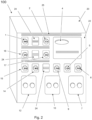
- Fig. 2 is a schematic illustration of a housing 20 with a liquid handling panel 22 of the fluid handling system in the form of a modular liquid chromatography system 100 of fig. 1 .
- the modular liquid chromatography system 100 comprises a plurality of fluid control valves in the form of: Injection valve 1, Column valve 2, Quaternary valve 5, Inlet valve B 6, Inlet valve A 9, Sample inlet valve 15, pH valve 17, and Outlet valve 18.
- the chromatography system 100 further comprises UV monitor 4, System pump B 7, System pump A 10, Sample pump 12, Mixer 14, and three Dummy modules 24.
- all liquid handling components and sensors arranged at the liquid handling panel 22 are designed to be readily interchangeable.
- each modular component is retained in a mating component position by a single screw, and it is connected to the master control unit by a single bus cable providing both communication and system power to each component.
- Fig. 3 is a schematic illustration of the housing with the liquid handling panel of fig. 2 with the modular components of the liquid chromatography system removed.
- Fig. 4b shows a Dummy module 24, which is intended to be placed in non used standard component positions.
- the Dummy modules are provided with mounting grooves for attachment of accessories to the system.
- the dummy module is shown as a panel member 28 without any internal section Figs. 4c and 4d shows a pump module and an UV-module, respectively, each having an external fluidics section 30 and an internal non-fluidics section 32.
- the interchangeable modular components26 comprises a panel member arranged to separate the fluidics section from the non fluidics section and for attachment to a component position in the liquid handling panel.
- Said panel attachment member may be arranged so that all fluid connections of said modular component are arranged on a wet side of the panel attachment member separating them from electrical components that are arranged on a dry side thereof, hence providing a high degree of liquid resistance at the external part of the fluid handling panel, and so that the liquid resistance requirements for the internal sections may be somewhat lightened.
- the interchangeable modular components are sealed against the liquid handling panel by a sealing member.
- the modular component does not comprise any panel member, but there is provided a suitable sealing arrangement between the component position openings of the liquid handling panel and the external surface of the interchangeable modular components 26.
- the component position openings of the liquid handling panel and the interchangeable modular components 26 are shown to have an essentially rectangular crossectional shape, but other shapes may be equally applicable.
- the liquid handling panel 22 of the fluid handling system may e.g. be designed in any suitable manner to allow the modular components to be arranged in an efficient manner.
- Figs. 5a and 5b shows a schematic embodiment of an automated fluid handling system wherein the housing 20 comprises an internal climate panel 29 arranged at a distance behind the liquid handling panel 22 defining an air inlet compartment 35 and air outlet compartment 37 in the housing 20, the climate panel 29 being provided with complementary component positions 39 for receiving the internal non fluidics section 32 of the interchangeable modular components 26, and wherein the non-fluidics section 32 of at least one interchangeable modular component is provided with one or more air inlet openings 31 located in the air inlet compartment 35 and one or more air outlet openings 33 located in the air outlet compartment 37 when the interchangeable modular component arranged in position in the component position.
- Fig. 5b shows the fluid handling system of fig. 5a in a schematic cross sectional view.
- air for cooling interchangeable modular components 26 provided with air inlet and outlet openings 31, 33 is preferably arranged to enter the air inlet compartment 35 at a distance from the outlet vent 43 in order to avoid recirculation of air.
- the air circulation in the system may be achieved by a system cooling unit (not shown) providing a flow of air from the air inlet compartment 35 to the air outlet compartment 37, through the at least one interchangeable modular component 26.
- the at least one interchangeable modular component 26 is provided with a local cooling unit (not shown) providing a flow of air from the air inlet compartment 35 to the air outlet compartment 37.
- the complementary component positions 39 are arranged to provide a relatively air flow tight fit with respect to the internal non fluidics section 32 of the interchangeable modular components 26, and according to one embodiment, this may be achieved by a sealing arrangement.
- a sealing member 45 for sealing the interchangeable modular components 26 with respect to the liquid handling panel 22, as discussed above.
- Other sealing member arrangements may be envisaged by a person skilled in the art.
- fluids are strictly restricted to the fluidics section 30 of the interchangeable modular component 26, but in alternative embodiments, only fluid connections are restricted to the fluidics section 30 allowing fluid to "cross" the fluid handling panel inside the non-fluidics section 30 of the interchangeable modular component 26.
- the component positions including the buss connectors 42 and the interchangeable modular components 26 are of plug and play configuration with respect to each other.
- Fig. 6 is a schematic illustration of an embodiment of a housing 20 with a modular liquid handling panel 22 with the modular components of the liquid chromatography system removed.
- the layout of the liquid handling panel 22 is configurable by means of two interchangeable panel sections 34 which may be selected in accordance with the desired layout of the system.
- two different layouts of the interchangeable panel sections are disclosed, but the layout may include any suitable configuration.
- Figs. 7a and 7b are schematic illustrations of an embodiment of a modular housing with a liquid handling panel with the modular components of the liquid chromatography system removed.
- the modular housing is comprised of a main housing 36 that comprises the master control unit including power supply and climate control for the whole housing, two expansion housing modules 38 and a side member 40.
- This approach provides very flexible expansion possibilities for the chromatography system, while preserving the benefits of a single master control unit including power supply and climate control.
- Fig. 8 is a schematic illustration of an embodiment of the system architecture of one embodiment of a modular liquid chromatography system according to the present invention.
- the chromatography system may comprise a master control unit 40 arranged to communicate with all modular components e.g. 1-26, over a system bus 42 such as a CAN-bus or the like.
- each modular component is provided with a dedicated CPU unit allowing the component to independently perform operations in response to instructions over the BUS 42.
- the bus 42 further comprises power feed for the modular components.
- the Bus 42 may be connected to any suitable number of modular components arranged in the housing 20, but also to one or more modular components 44 outside of the housing 20 or the like.
- the master control unit may further be arranged to control the climate in the housing.
- other components of the chromatography system e.g. a fraction collector or the like, may be arranged in the housing and the controlled climate therein.
- different component modules are automatically identified by the master control unit, whereby they may be moved essentially freely between different positions.
- the master control unit may be arranged to provide said information to Chromatography control software whereby experimental setup and planning may be performed.
- the control system may be arranged to provide an optimized layout of the component modules with respect to the present layout of the liquid handling panel and available component modules for a specific experimental setup.
- each interchangeable panel section 34 and expansion housing module 38 of figs. 6a and 6b may be provided with means for automatic detection of the same to allow automatic configuration of the system by the master control unit 40.
- each interchangeable panel section 34 and expansion housing module 38 comprises a hub (not shown) for connection to the system bus 42 in order to expand the system bus 42 network to the number of component modules in each interchangeable panel section 34 or expansion housing module 38.
- Fig. 9 is a schematic illustration of an embodiment of a master control unit of one embodiment of a modular liquid chromatography system according to the present invention.
- the master control unit 40 comprises a system controller 46 for communicating with internal and external components and control computers (not shown)etc.
- the system controller comprises a suitable CPU 48, a bus controller 52, an external communications controller 50, such as a LAN unit, and a storage device 54.
- the bus controller 52 is providing communication with the component modules.
- the master control unit may further comprise a Power supply 56 and a climate controller 58 arranged to keep the internal climate in the housing 20 at a predetermined level as discussed above.
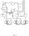
- Fig. 10 is a schematic illustration of one embodiment of a fluidic interconnection arrangement between the modular components of the liquid handling panel. Taking into account the complexity of the disclosed interconnection arrangement, the benefit of optimizing the fluid paths in alternative configurations of the system becomes evident.
- the task of optimizing the fluid paths may e.g. be performed to reduce the total length/volume of the fluid paths/tubing arranged to interconnect the different component modules in the system.
- the optimization may be performed to minimize the length/volume of one or more specific fluid paths, such as the sample output path from the column to the fraction collector, in order to minimize dispersion of the fractionized sample.
Landscapes
- Chemical & Material Sciences (AREA)
- Analytical Chemistry (AREA)
- General Health & Medical Sciences (AREA)
- Life Sciences & Earth Sciences (AREA)
- Health & Medical Sciences (AREA)
- Biochemistry (AREA)
- Physics & Mathematics (AREA)
- General Physics & Mathematics (AREA)
- Immunology (AREA)
- Pathology (AREA)
- Chemical Kinetics & Catalysis (AREA)
- Treatment Of Liquids With Adsorbents In General (AREA)
- Valve Housings (AREA)
- Physical Or Chemical Processes And Apparatus (AREA)
Applications Claiming Priority (4)
| Application Number | Priority Date | Filing Date | Title |
|---|---|---|---|
| SE0950431 | 2009-06-09 | ||
| EP10786454.8A EP2440913B1 (de) | 2009-06-09 | 2010-06-04 | Automatisiertes flüssigchromatographie-system mit flüssigkeitsbehandlungssystem |
| PCT/SE2010/050624 WO2010144037A1 (en) | 2009-06-09 | 2010-06-04 | Automated fluid handling system |
| EP16205536.2A EP3168614B1 (de) | 2009-06-09 | 2010-06-04 | Automatisiertes flüssigkeitsbehandlungssystem für flüssigkeitschromatographie-anwendungen |
Related Parent Applications (2)
| Application Number | Title | Priority Date | Filing Date |
|---|---|---|---|
| EP10786454.8A Division EP2440913B1 (de) | 2009-06-09 | 2010-06-04 | Automatisiertes flüssigchromatographie-system mit flüssigkeitsbehandlungssystem |
| EP16205536.2A Division EP3168614B1 (de) | 2009-06-09 | 2010-06-04 | Automatisiertes flüssigkeitsbehandlungssystem für flüssigkeitschromatographie-anwendungen |
Publications (4)
| Publication Number | Publication Date |
|---|---|
| EP4488679A2 true EP4488679A2 (de) | 2025-01-08 |
| EP4488679A3 EP4488679A3 (de) | 2025-03-19 |
| EP4488679B1 EP4488679B1 (de) | 2026-01-14 |
| EP4488679C0 EP4488679C0 (de) | 2026-01-14 |
Family
ID=43309100
Family Applications (3)
| Application Number | Title | Priority Date | Filing Date |
|---|---|---|---|
| EP10786454.8A Active EP2440913B1 (de) | 2009-06-09 | 2010-06-04 | Automatisiertes flüssigchromatographie-system mit flüssigkeitsbehandlungssystem |
| EP16205536.2A Active EP3168614B1 (de) | 2009-06-09 | 2010-06-04 | Automatisiertes flüssigkeitsbehandlungssystem für flüssigkeitschromatographie-anwendungen |
| EP24213530.9A Active EP4488679B1 (de) | 2009-06-09 | 2010-06-04 | Automatisiertes flüssigkeitshandhabungssystem für anwendungen in hochdruckflüssigkeitschromatographie |
Family Applications Before (2)
| Application Number | Title | Priority Date | Filing Date |
|---|---|---|---|
| EP10786454.8A Active EP2440913B1 (de) | 2009-06-09 | 2010-06-04 | Automatisiertes flüssigchromatographie-system mit flüssigkeitsbehandlungssystem |
| EP16205536.2A Active EP3168614B1 (de) | 2009-06-09 | 2010-06-04 | Automatisiertes flüssigkeitsbehandlungssystem für flüssigkeitschromatographie-anwendungen |
Country Status (6)
| Country | Link |
|---|---|
| US (11) | USRE47124E1 (de) |
| EP (3) | EP2440913B1 (de) |
| JP (1) | JP5856952B2 (de) |
| CN (2) | CN105203689B (de) |
| CA (1) | CA2762900C (de) |
| WO (1) | WO2010144037A1 (de) |
Families Citing this family (33)
| Publication number | Priority date | Publication date | Assignee | Title |
|---|---|---|---|---|
| WO2010144037A1 (en) | 2009-06-09 | 2010-12-16 | Ge Healthcare Bio-Sciences Ab | Automated fluid handling system |
| US9304518B2 (en) * | 2011-08-24 | 2016-04-05 | Bio-Rad Laboratories, Inc. | Modular automated chromatography system |
| US9182886B2 (en) | 2011-11-14 | 2015-11-10 | Bio-Rad Laboratories Inc. | Chromatography configuration interface |
| WO2015011522A1 (en) * | 2013-07-23 | 2015-01-29 | Tubitak Ume | Multi-task sample preparation system with reconfigurable modules for on-line dilution, enzymatic digestion and fractionation |
| JP1516820S (de) * | 2014-07-01 | 2015-02-09 | ||
| US9987414B2 (en) * | 2014-08-07 | 2018-06-05 | Erol Bars | System for delivery of fluids such as ammonia nitrogen 13 |
| US10780410B2 (en) | 2014-08-15 | 2020-09-22 | Massachusetts Institute Of Technology | Systems and methods for synthesizing chemical products, including active pharmaceutical ingredients |
| EP3452220A4 (de) | 2016-05-02 | 2020-01-01 | Massachusetts Institute of Technology | Rekonfigurierbares mehrstufiges chemisches synthesesystem und zugehörige komponenten und verfahren |
| GB201704763D0 (de) * | 2017-01-05 | 2017-05-10 | Illumina Inc | |
| GB201703233D0 (en) * | 2017-02-28 | 2017-04-12 | Ge Healthcare Bio Sciences Ab | A modular bio-processing unit and a bio-processing system employing plural units |
| EP3381530A1 (de) * | 2017-03-29 | 2018-10-03 | EMD Millipore Corporation | Anlage zur behandlung einer biologischen flüssigkeit |
| GB201710279D0 (en) | 2017-06-28 | 2017-08-09 | Ge Healthcare Bio Sciences Ab | Improvements in and relating to bioprocessing equipment and fluid couplings therefor |
| GB201715403D0 (en) * | 2017-09-22 | 2017-11-08 | Ge Healthcare Bio Sciences Ab | Chromatography apparatus |
| GB201808801D0 (en) | 2018-05-30 | 2018-07-11 | Ge Healthcare | Bioprocess system and method providing automated configuration detection |
| JP7031507B2 (ja) * | 2018-06-18 | 2022-03-08 | 株式会社島津製作所 | サンプル温調機能を備えた装置 |
| EP3814282A4 (de) | 2018-06-28 | 2022-03-02 | Aquacycl, Inc. | Skalierbare mikrobielle brennstoffzellen mit kontinuierlichem fluss |
| US11552322B2 (en) | 2018-07-24 | 2023-01-10 | Aquacycl, Inc. | Branched anodes for microbial fuel cells |
| KR102375602B1 (ko) | 2018-07-28 | 2022-03-18 | 한국과학기술원 | 모듈형 유체 칩 및 이를 포함하는 유체 유동 시스템 |
| USD875208S1 (en) * | 2018-07-31 | 2020-02-11 | Aquacycl Llc | Bioelectrochemical reactor |
| USD875207S1 (en) * | 2018-07-31 | 2020-02-11 | Aquacycl Llc | Bioelectrochemical reactor |
| JP7259870B2 (ja) * | 2019-01-11 | 2023-04-18 | 株式会社島津製作所 | 液体クロマトグラフに使用されるミキサおよび液体クロマトグラフ |
| EP3699697A1 (de) | 2019-02-25 | 2020-08-26 | Bayer Aktiengesellschaft | Automatisierte gleichzeitige prozesssteuerung |
| CA3131773A1 (en) | 2019-02-27 | 2020-09-03 | Aquacycl Llc | Scalable floating micro-aeration unit, devices and methods |
| CN110131783B (zh) * | 2019-05-15 | 2020-01-07 | 北京市众诚恒祥能源投资管理有限公司 | 一种高效节能集中供热自动化控制装置 |
| JP7388206B2 (ja) * | 2020-01-22 | 2023-11-29 | 株式会社島津製作所 | 液体クロマトグラフおよび分析方法 |
| US11604482B2 (en) | 2020-03-16 | 2023-03-14 | Aquacycl, Inc. | Fluid flow control for water treatment systems |
| JP7571554B2 (ja) * | 2021-01-14 | 2024-10-23 | 株式会社島津製作所 | pH測定装置及び液体クロマトグラフ |
| US20240402151A1 (en) * | 2021-10-21 | 2024-12-05 | Siemens Healthcare Diagnostics Inc. | Fluidic tubing assembly for blood analyzer |
| EP4212872A1 (de) | 2022-01-18 | 2023-07-19 | Metrohm AG | Modulares flüssigkeitschromatographiesystem |
| USD1039167S1 (en) * | 2022-09-23 | 2024-08-13 | Norroy Bioscience Co., Ltd. | Radiopharmaceutical synthesis device |
| USD1046191S1 (en) * | 2022-10-06 | 2024-10-08 | Eppendorf Se | Hand-operated instrument and tool for laboratories |
| USD1035035S1 (en) * | 2022-11-11 | 2024-07-09 | Biosys Usa Llc | Biochemical analyzer |
| USD1091858S1 (en) * | 2024-01-29 | 2025-09-02 | Inventage Lab Inc. | Lipid nanoparticle preparation device |
Family Cites Families (51)
| Publication number | Priority date | Publication date | Assignee | Title |
|---|---|---|---|---|
| US8003A (en) * | 1851-03-25 | Improvement in scythe-tastenings | ||
| DE1418503U (de) | ||||
| DE1984739U (de) | 1968-02-13 | 1968-05-02 | Schlenker Maier Elektro Joh | Heisswasserbereiter. |
| US4044593A (en) | 1971-03-31 | 1977-08-30 | Shimadzu Seisakusho Ltd. | Chromatograph |
| GB1418503A (en) | 1972-06-14 | 1975-12-24 | Barker P E | Chromatographic apparatus |
| DE2646640C2 (de) * | 1976-10-15 | 1982-05-06 | Bayer Ag, 5090 Leverkusen | Verfahren und Vorrichtung für Mehrfachentwicklungen von Dünnschichtchromatographieplatten |
| SE414554B (sv) * | 1977-02-16 | 1980-08-04 | Bifok Ab | Sett vid kontinuerlig genomstromningsanalys, der en oavbruten, laminer berarstromning, icke segmenterad av luftblasor, genom en huvudledning transporterar en provplugg till en genomstromningsdetektor samt anordning ... |
| DE3785207T2 (de) * | 1987-09-26 | 1993-07-15 | Hewlett Packard Gmbh | Pumpvorrichtung zur abgabe von fluessigkeit bei hohem druck. |
| GB2220369B (en) | 1988-06-10 | 1993-01-27 | Inst Of Child Health | Method for testing body fluids by low pressure liquid chromatography |
| US5065614A (en) * | 1990-07-31 | 1991-11-19 | Rutgers University | Short path thermal desorption apparatus for use in gas chromatography techniques |
| GB9020306D0 (en) * | 1990-09-17 | 1990-10-31 | Dynochrom A S | Improvements in or relating to chromatography |
| US5792742A (en) * | 1991-06-14 | 1998-08-11 | New York University | Fibrin-binding peptide fragments of fibronectin |
| US6190617B1 (en) * | 1992-03-27 | 2001-02-20 | Abbott Laboratories | Sample container segment assembly |
| US5766460A (en) * | 1992-11-02 | 1998-06-16 | Pharmacia Biotech Ab | Liquid chromatographic system |
| US5580523A (en) * | 1994-04-01 | 1996-12-03 | Bard; Allen J. | Integrated chemical synthesizers |
| US5896273A (en) | 1996-12-31 | 1999-04-20 | Compaq Computer Corp. | Modular computer chassis interchangeable between stand alone and rack mounted states |
| US5959841A (en) | 1996-12-31 | 1999-09-28 | Compaq Computer Corp. | Modular computer chassis with extractor device mounted to the housing |
| DE19847439C2 (de) | 1998-10-08 | 2001-10-18 | Sepiatec Gmbh | Verfahren und Vorrichtung zur flüssigchromatographischen Trennung von Substanzgemischen und Identifizierung von Substanzen |
| US20020185442A1 (en) * | 1998-10-30 | 2002-12-12 | Maiefski Romaine R. | Sample separation apparatus and method for multiple channel high throughput purification |
| US7445756B2 (en) * | 1999-06-03 | 2008-11-04 | Fenwal, Inc. | Fluid processing sets and organizers for the same |
| US6355164B1 (en) | 1999-10-29 | 2002-03-12 | Ontogen Corporation | Sample collection apparatus and method for multiple channel high throughput purification |
| DE19954855C1 (de) | 1999-11-15 | 2001-04-05 | Siemens Ag | System zur automatisierten Behandlung von Fluiden, mit einanderreihbaren, austauschbaren Prozeßmodulen |
| US6599484B1 (en) * | 2000-05-12 | 2003-07-29 | Cti, Inc. | Apparatus for processing radionuclides |
| JP2004508919A (ja) | 2000-05-24 | 2004-03-25 | セルラー プロセス ケミストリー インコーポレイテッド | マイクロリアクタを組み入れたモジュラ式化学生産システム |
| US6434018B1 (en) | 2000-10-27 | 2002-08-13 | Rittal Corp. | Rack mount system for pluggable computer modules |
| JP4348025B2 (ja) * | 2001-05-09 | 2009-10-21 | 株式会社日立製作所 | 分離分析装置 |
| EP1404430B1 (de) * | 2001-06-22 | 2011-10-05 | PG Research Foundation, Inc. | Automatisiertes system und verfahren zur trennung von radionukliden |
| CN2567575Y (zh) | 2002-09-16 | 2003-08-20 | 张天龙 | 分析单元模块化的气相色谱仪 |
| WO2004040295A1 (en) | 2002-10-31 | 2004-05-13 | Nanostream, Inc. | Parallel detection chromatography systems |
| US6968958B2 (en) | 2002-11-07 | 2005-11-29 | Hewlett-Packard Development Company, L.P. | Stackable and detachably coupled electronic device modules |
| US6741463B1 (en) | 2003-01-31 | 2004-05-25 | Dell Products L.P. | Rack mountable docking station |
| US20040264145A1 (en) | 2003-05-08 | 2004-12-30 | Miller Greg F. | Compact electronic component system and method |
| DE602004007732T2 (de) | 2003-09-09 | 2008-04-10 | Tosoh Corp., Shunan | Flüssigchromatographievorrichtung |
| JP4561249B2 (ja) | 2003-09-09 | 2010-10-13 | 東ソー株式会社 | 液体クロマトグラフ装置 |
| DK2322278T3 (en) | 2003-10-24 | 2017-04-10 | Aushon Biosystems Inc | Apparatus and method for dispensing liquid, semi-solid and solid samples |
| US7932090B2 (en) | 2004-08-05 | 2011-04-26 | 3M Innovative Properties Company | Sample processing device positioning apparatus and methods |
| US20060047466A1 (en) | 2004-08-27 | 2006-03-02 | White Gene H | System and method for monitoring rack equipment |
| CA2602818C (en) * | 2005-03-31 | 2013-03-26 | Ashland Licensing And Intellectual Property Llc | Apparatuses and systems for monitoring fouling of aqueous systems including enhanced heat exchanger tubes |
| US7910067B2 (en) | 2005-04-19 | 2011-03-22 | Gen-Probe Incorporated | Sample tube holder |
| US7689391B2 (en) | 2005-05-20 | 2010-03-30 | Hewlett-Packard Development Company, L.P. | Data structure relating a device characteristic to a device position in a support structure |
| DE102005028897A1 (de) * | 2005-06-17 | 2006-12-28 | Eckert & Ziegler Eurotope Gmbh | Anordnung und Verfahren zur Verarbeitung von chemischen Stoffen, Computerprogramm zur Steuerung einer solchen Anordnung sowie ein entsprechendes computerlesbares Speichermedium |
| US8348731B2 (en) | 2005-08-05 | 2013-01-08 | Wilmington Research And Development Corporation | Adaptive cooling method for computer rack enclosure |
| CA2621030C (en) | 2005-09-02 | 2011-10-11 | Abb Inc. | Modular gas chromatograph |
| GB0519898D0 (en) | 2005-09-30 | 2005-11-09 | Bioniqs Ltd | Liquids |
| US7791890B2 (en) | 2005-10-07 | 2010-09-07 | Nec Corporation | Computer system |
| US7589974B2 (en) | 2006-04-21 | 2009-09-15 | Helwett-Packard Development Company, L.P. | Modular server and method |
| KR100835355B1 (ko) | 2006-07-25 | 2008-06-04 | 삼성전자주식회사 | 플라즈마를 이용한 이온주입장치 |
| US7641242B2 (en) | 2006-08-12 | 2010-01-05 | Corsolutions, Llc | Compression connection |
| US7586102B2 (en) | 2006-08-14 | 2009-09-08 | Board Of Regents The University Of Texas System | Automated system for formulating radiopharmaceuticals |
| CN101358952A (zh) | 2008-03-28 | 2009-02-04 | 张西咸 | 一种模块化组合结构的便携式化学品快速检测仪 |
| WO2010144037A1 (en) | 2009-06-09 | 2010-12-16 | Ge Healthcare Bio-Sciences Ab | Automated fluid handling system |
-
2010
- 2010-06-04 WO PCT/SE2010/050624 patent/WO2010144037A1/en not_active Ceased
- 2010-06-04 US US15/008,155 patent/USRE47124E1/en active Active
- 2010-06-04 EP EP10786454.8A patent/EP2440913B1/de active Active
- 2010-06-04 US US13/376,929 patent/US8821718B2/en not_active Ceased
- 2010-06-04 CN CN201510602257.9A patent/CN105203689B/zh active Active
- 2010-06-04 EP EP16205536.2A patent/EP3168614B1/de active Active
- 2010-06-04 EP EP24213530.9A patent/EP4488679B1/de active Active
- 2010-06-04 JP JP2012514920A patent/JP5856952B2/ja active Active
- 2010-06-04 CN CN201080026149.7A patent/CN102803948B/zh active Active
- 2010-06-04 CA CA2762900A patent/CA2762900C/en active Active
-
2014
- 2014-08-19 US US14/463,039 patent/US9404902B2/en active Active
-
2016
- 2016-05-26 US US15/165,876 patent/US9709589B2/en active Active
- 2016-07-08 US US15/205,919 patent/US9709590B2/en active Active
- 2016-07-08 US US15/205,956 patent/US9709591B2/en active Active
- 2016-09-09 US US15/261,250 patent/US9671420B2/en active Active
-
2017
- 2017-06-15 US US15/624,547 patent/US10598678B2/en active Active
-
2020
- 2020-02-12 US US16/788,836 patent/US11650219B2/en active Active
-
2023
- 2023-04-05 US US18/131,043 patent/US12072344B2/en active Active
-
2024
- 2024-07-24 US US18/782,221 patent/US20240377425A1/en active Pending
Also Published As
Similar Documents
| Publication | Publication Date | Title |
|---|---|---|
| US12072344B2 (en) | Automated fluid handling system | |
| JP2012529650A5 (de) | ||
| KR20230083325A (ko) | 개별 분리 유닛 및/또는 기능 유닛을 상호 연결 및 고정 배열하기 위한 모듈러 장치 | |
| HK1219532B (en) | Automated fluid handling system | |
| US12411115B2 (en) | Compact and modular capillary liquid chromatography system | |
| HK1178606B (en) | Automated fluid handling system | |
| CN212476752U (zh) | 一种汇流体结构及半导体测序系统 | |
| CN222416133U (zh) | 一种阀集成模块、液路系统以及基因测序仪 | |
| JP2025504441A (ja) | モジュール式液体クロマトグラフィシステム |
Legal Events
| Date | Code | Title | Description |
|---|---|---|---|
| PUAI | Public reference made under article 153(3) epc to a published international application that has entered the european phase |
Free format text: ORIGINAL CODE: 0009012 |
|
| STAA | Information on the status of an ep patent application or granted ep patent |
Free format text: STATUS: REQUEST FOR EXAMINATION WAS MADE |
|
| 17P | Request for examination filed |
Effective date: 20241118 |
|
| AC | Divisional application: reference to earlier application |
Ref document number: 2440913 Country of ref document: EP Kind code of ref document: P Ref document number: 3168614 Country of ref document: EP Kind code of ref document: P |
|
| AK | Designated contracting states |
Kind code of ref document: A2 Designated state(s): AL AT BE BG CH CY CZ DE DK EE ES FI FR GB GR HR HU IE IS IT LI LT LU LV MC MK MT NL NO PL PT RO SE SI SK SM TR |
|
| REG | Reference to a national code |
Ref country code: DE Ref legal event code: R079 Free format text: PREVIOUS MAIN CLASS: G01N0033000000 Ipc: G01N0030820000 Ref country code: DE Ref legal event code: R079 Ref document number: 602010069942 Country of ref document: DE Free format text: PREVIOUS MAIN CLASS: G01N0033000000 Ipc: G01N0030820000 |
|
| PUAL | Search report despatched |
Free format text: ORIGINAL CODE: 0009013 |
|
| AK | Designated contracting states |
Kind code of ref document: A3 Designated state(s): AL AT BE BG CH CY CZ DE DK EE ES FI FR GB GR HR HU IE IS IT LI LT LU LV MC MK MT NL NO PL PT RO SE SI SK SM TR |
|
| RIC1 | Information provided on ipc code assigned before grant |
Ipc: G01N 27/416 20060101ALN20250211BHEP Ipc: G01N 35/00 20060101ALN20250211BHEP Ipc: B01D 15/08 20060101ALN20250211BHEP Ipc: G01N 30/88 20060101ALN20250211BHEP Ipc: G01N 33/00 20060101ALI20250211BHEP Ipc: H05K 7/20 20060101ALI20250211BHEP Ipc: G06F 1/20 20060101ALI20250211BHEP Ipc: F16K 27/00 20060101ALI20250211BHEP Ipc: B01D 15/10 20060101ALI20250211BHEP Ipc: G01N 30/24 20060101ALI20250211BHEP Ipc: B01D 15/14 20060101ALI20250211BHEP Ipc: G01N 30/82 20060101AFI20250211BHEP |
|
| GRAP | Despatch of communication of intention to grant a patent |
Free format text: ORIGINAL CODE: EPIDOSNIGR1 |
|
| STAA | Information on the status of an ep patent application or granted ep patent |
Free format text: STATUS: GRANT OF PATENT IS INTENDED |
|
| GRAJ | Information related to disapproval of communication of intention to grant by the applicant or resumption of examination proceedings by the epo deleted |
Free format text: ORIGINAL CODE: EPIDOSDIGR1 |
|
| RIC1 | Information provided on ipc code assigned before grant |
Ipc: G01N 30/82 20060101AFI20250702BHEP Ipc: B01D 15/14 20060101ALI20250702BHEP Ipc: G01N 30/24 20060101ALI20250702BHEP Ipc: B01D 15/10 20060101ALI20250702BHEP Ipc: F16K 27/00 20060101ALI20250702BHEP Ipc: G06F 1/20 20060101ALI20250702BHEP Ipc: H05K 7/20 20060101ALI20250702BHEP Ipc: G01N 33/00 20060101ALI20250702BHEP Ipc: G01N 30/88 20060101ALN20250702BHEP Ipc: B01D 15/08 20060101ALN20250702BHEP Ipc: G01N 35/00 20060101ALN20250702BHEP Ipc: G01N 27/416 20060101ALN20250702BHEP |
|
| STAA | Information on the status of an ep patent application or granted ep patent |
Free format text: STATUS: REQUEST FOR EXAMINATION WAS MADE |
|
| INTG | Intention to grant announced |
Effective date: 20250717 |
|
| INTC | Intention to grant announced (deleted) | ||
| GRAP | Despatch of communication of intention to grant a patent |
Free format text: ORIGINAL CODE: EPIDOSNIGR1 |
|
| STAA | Information on the status of an ep patent application or granted ep patent |
Free format text: STATUS: GRANT OF PATENT IS INTENDED |
|
| RIC1 | Information provided on ipc code assigned before grant |
Ipc: G06F 1/20 20060101ALI20250825BHEP Ipc: G01N 30/82 20060101AFI20250825BHEP Ipc: B01D 15/14 20060101ALI20250825BHEP Ipc: G01N 30/24 20060101ALI20250825BHEP Ipc: B01D 15/10 20060101ALI20250825BHEP Ipc: F16K 27/00 20060101ALI20250825BHEP Ipc: H05K 7/20 20060101ALI20250825BHEP Ipc: G01N 33/00 20060101ALI20250825BHEP Ipc: G01N 30/88 20060101ALN20250825BHEP Ipc: B01D 15/08 20060101ALN20250825BHEP Ipc: G01N 35/00 20060101ALN20250825BHEP Ipc: G01N 27/416 20060101ALN20250825BHEP |
|
| RIC1 | Information provided on ipc code assigned before grant |
Ipc: G01N 30/82 20060101AFI20250903BHEP Ipc: B01D 15/14 20060101ALI20250903BHEP Ipc: G01N 30/24 20060101ALI20250903BHEP Ipc: B01D 15/10 20060101ALI20250903BHEP Ipc: F16K 27/00 20060101ALI20250903BHEP Ipc: G06F 1/20 20060101ALI20250903BHEP Ipc: H05K 7/20 20060101ALI20250903BHEP Ipc: G01N 33/00 20060101ALI20250903BHEP Ipc: G01N 30/88 20060101ALN20250903BHEP Ipc: B01D 15/08 20060101ALN20250903BHEP Ipc: G01N 35/00 20060101ALN20250903BHEP Ipc: G01N 27/416 20060101ALN20250903BHEP |
|
| INTG | Intention to grant announced |
Effective date: 20250916 |
|
| GRAS | Grant fee paid |
Free format text: ORIGINAL CODE: EPIDOSNIGR3 |
|
| GRAA | (expected) grant |
Free format text: ORIGINAL CODE: 0009210 |
|
| STAA | Information on the status of an ep patent application or granted ep patent |
Free format text: STATUS: THE PATENT HAS BEEN GRANTED |
|
| AC | Divisional application: reference to earlier application |
Ref document number: 3168614 Country of ref document: EP Kind code of ref document: P Ref document number: 2440913 Country of ref document: EP Kind code of ref document: P |
|
| AK | Designated contracting states |
Kind code of ref document: B1 Designated state(s): AL AT BE BG CH CY CZ DE DK EE ES FI FR GB GR HR HU IE IS IT LI LT LU LV MC MK MT NL NO PL PT RO SE SI SK SM TR |
|
| REG | Reference to a national code |
Ref country code: CH Ref legal event code: F10 Free format text: ST27 STATUS EVENT CODE: U-0-0-F10-F00 (AS PROVIDED BY THE NATIONAL OFFICE) Effective date: 20260114 Ref country code: GB Ref legal event code: FG4D |
|
| REG | Reference to a national code |
Ref country code: CH Ref legal event code: R17 Free format text: ST27 STATUS EVENT CODE: U-0-0-R10-R17 (AS PROVIDED BY THE NATIONAL OFFICE) Effective date: 20260119 |
|
| REG | Reference to a national code |
Ref country code: DE Ref legal event code: R096 Ref document number: 602010069942 Country of ref document: DE |
|
| REG | Reference to a national code |
Ref country code: IE Ref legal event code: FG4D |
|
| U01 | Request for unitary effect filed |
Effective date: 20260203 |
|
| U07 | Unitary effect registered |
Designated state(s): AT BE BG DE DK EE FI FR IT LT LU LV MT NL PT RO SE SI Effective date: 20260210 |