EP4471346A2 - Informationsübernahmesystem, zweite platte, klimaanlagenvorrichtung und informationsübernahmeverfahren - Google Patents
Informationsübernahmesystem, zweite platte, klimaanlagenvorrichtung und informationsübernahmeverfahren Download PDFInfo
- Publication number
- EP4471346A2 EP4471346A2 EP24206086.1A EP24206086A EP4471346A2 EP 4471346 A2 EP4471346 A2 EP 4471346A2 EP 24206086 A EP24206086 A EP 24206086A EP 4471346 A2 EP4471346 A2 EP 4471346A2
- Authority
- EP
- European Patent Office
- Prior art keywords
- board
- information
- control unit
- control
- unit
- Prior art date
- Legal status (The legal status is an assumption and is not a legal conclusion. Google has not performed a legal analysis and makes no representation as to the accuracy of the status listed.)
- Granted
Links
Images



Classifications
-
- F—MECHANICAL ENGINEERING; LIGHTING; HEATING; WEAPONS; BLASTING
- F24—HEATING; RANGES; VENTILATING
- F24F—AIR-CONDITIONING; AIR-HUMIDIFICATION; VENTILATION; USE OF AIR CURRENTS FOR SCREENING
- F24F11/00—Control or safety arrangements
- F24F11/89—Arrangement or mounting of control or safety devices
-
- F—MECHANICAL ENGINEERING; LIGHTING; HEATING; WEAPONS; BLASTING
- F24—HEATING; RANGES; VENTILATING
- F24F—AIR-CONDITIONING; AIR-HUMIDIFICATION; VENTILATION; USE OF AIR CURRENTS FOR SCREENING
- F24F11/00—Control or safety arrangements
- F24F11/30—Control or safety arrangements for purposes related to the operation of the system, e.g. for safety or monitoring
-
- F—MECHANICAL ENGINEERING; LIGHTING; HEATING; WEAPONS; BLASTING
- F24—HEATING; RANGES; VENTILATING
- F24F—AIR-CONDITIONING; AIR-HUMIDIFICATION; VENTILATION; USE OF AIR CURRENTS FOR SCREENING
- F24F11/00—Control or safety arrangements
- F24F11/30—Control or safety arrangements for purposes related to the operation of the system, e.g. for safety or monitoring
- F24F11/32—Responding to malfunctions or emergencies
-
- F—MECHANICAL ENGINEERING; LIGHTING; HEATING; WEAPONS; BLASTING
- F24—HEATING; RANGES; VENTILATING
- F24F—AIR-CONDITIONING; AIR-HUMIDIFICATION; VENTILATION; USE OF AIR CURRENTS FOR SCREENING
- F24F11/00—Control or safety arrangements
- F24F11/30—Control or safety arrangements for purposes related to the operation of the system, e.g. for safety or monitoring
- F24F11/46—Improving electric energy efficiency or saving
-
- F—MECHANICAL ENGINEERING; LIGHTING; HEATING; WEAPONS; BLASTING
- F24—HEATING; RANGES; VENTILATING
- F24F—AIR-CONDITIONING; AIR-HUMIDIFICATION; VENTILATION; USE OF AIR CURRENTS FOR SCREENING
- F24F11/00—Control or safety arrangements
- F24F11/30—Control or safety arrangements for purposes related to the operation of the system, e.g. for safety or monitoring
- F24F11/49—Control or safety arrangements for purposes related to the operation of the system, e.g. for safety or monitoring ensuring correct operation, e.g. by trial operation or configuration checks
-
- F—MECHANICAL ENGINEERING; LIGHTING; HEATING; WEAPONS; BLASTING
- F24—HEATING; RANGES; VENTILATING
- F24F—AIR-CONDITIONING; AIR-HUMIDIFICATION; VENTILATION; USE OF AIR CURRENTS FOR SCREENING
- F24F11/00—Control or safety arrangements
- F24F11/50—Control or safety arrangements characterised by user interfaces or communication
- F24F11/52—Indication arrangements, e.g. displays
-
- F—MECHANICAL ENGINEERING; LIGHTING; HEATING; WEAPONS; BLASTING
- F24—HEATING; RANGES; VENTILATING
- F24F—AIR-CONDITIONING; AIR-HUMIDIFICATION; VENTILATION; USE OF AIR CURRENTS FOR SCREENING
- F24F11/00—Control or safety arrangements
- F24F11/88—Electrical aspects, e.g. circuits
Definitions
- the present disclosure relates to an information takeover system, a second board, an air conditioning apparatus, and an information takeover method.
- PATENT LITERATURE 1 Japanese Laid-Open Patent Publication No. 2007-318572
- Patent Literature 1 it is necessary to back up the information stored in the memory of the defective control board and to transfer the backed up information to the memory of the new control board, with a personal computer or the like connected to the air conditioning apparatus. This results in a problem that the backup and transfer of the information stored in the memory take time and effort.
- An object of the present disclosure is to take over information about an air conditioning apparatus with ease.
- the first control unit is configured to perform first control to transmit the first information to the second board with the first board and the second board connected to each other in the information exchangeable manner.
- the first control unit of the first board performs the first control with the first board and the second board connected to each other in the information exchangeable manner, thereby transmitting, to the second board, the first information stored in the first storage unit of the first board.
- This configuration facilitates takeover of the first information about the air conditioning apparatus from the first board to the second board.
- the first control unit or the second control unit receives a first signal serving as a trigger for performing the first control, with the first board and the second board connected to each other in the information exchangeable manner.
- This configuration enables automatic performance of the first control in such a manner that the first control unit or the second control unit receives the first signal.
- the second control unit requests the first control unit to transmit the first information when receiving the first signal with the first board and the second board connected to each other in the information exchangeable manner.
- This configuration facilitates transmission of the first information from the first board to the second board in such a manner that the first control unit performs the first control in response to the request from the second control unit.
- the information takeover system further includes a cable configured to connect the first board and the second board to each other in the information exchangeable manner.
- This configuration enables transmission, to the second board, the first information stored in the first storage unit of the first board, in such a manner that the first control unit performs the first control with the first board and the second board connected to each other with the cable.
- the information takeover system further includes a cable configured to connect the first board and the second board to each other in the information exchangeable manner,
- This configuration allows the second control unit to automatically receive the first signal in such a manner that the first board and the second board are connected to each other with the cable.
- the second board further includes a second storage unit in which the first information is storable, and the second control unit determines whether to store, in the second storage unit, the first information received by the first control from the first board, based on a version of the first information.
- This configuration suppresses the occurrence of malfunction owing to a difference in version, in such a manner that the second control unit does not store the first information in the second storage unit when the version of the first information is old, for example.
- the second board further includes a second storage unit in which the first information is storable, and the second control unit does not store, in the second storage unit, the first information received by the first control from the first board on condition that the first information is empty.
- This configuration suppresses a situation in which the empty first information received from the first board is stored in the second storage unit of the second board.
- one of the first board and the second board is electrically connected to a power supply of the air conditioning apparatus, and a remaining one of the first board and the second board receives electric power from the one of the first board and the second board.
- the cable may be equipped with a battery.
- This configuration enables supply of electric power from the battery on the cable to each of the first board and the second board in such a manner that the first board and the second board are connected to each other with the cable.
- This configuration enables takeover of the first information from the first board to the second board even at a place distant from the air conditioning apparatus.
- a second board according to the present disclosure is connectable, in an information exchangeable manner, to a first board including a first storage unit storing first information about an air conditioning apparatus and a first control unit configured to perform first control to transmit the first information.
- the second board includes a second control unit configured to request the first control unit to transmit the first information with the first board and the second board connected to each other in the information exchangeable manner.
- the first control unit of the first board performs the first control in such a manner that the second control unit requests the first control unit to transmit the first information with the first board and the second board connected to each other in the information exchangeable manner.
- This configuration allows the second board to receive the first information stored in the first storage unit of the first board. This configuration therefore facilitates takeover of the first information about the air conditioning apparatus from the first board to the second board.
- the second control unit requests the first control unit to transmit the first information when receiving a first signal serving as a trigger for performing the first control with the first board and the second board connected to each other in the information exchangeable manner.
- This configuration allows the first control unit to automatically perform the first control in such a manner that the second control unit receives the first signal and makes the request for transmission of the first information.
- the second board further includes a connection unit to be connected to a cable through which information is exchangeable between the first board and the second board, and the connection unit includes a terminal to which the first signal is input with the cable connected to the connection unit.
- This configuration allows the second control unit to receive the first signal in such a manner that the first board and the second board are connected to each other with the cable.
- An air conditioning apparatus includes the second board as recited in any of (10) to (12).
- the first control unit of the first board performs the first control in such a manner that the second control unit requests the first control unit to transmit the first information with the first board and the second board connected to each other in the information exchangeable manner.
- This configuration allows the second board to receive the first information stored in the first storage unit of the first board. This configuration therefore facilitates takeover of the first information about the air conditioning apparatus from the first board to the second board.
- An information takeover method is a method for taking over first information about an air conditioning apparatus, the first information being stored in a first storage unit of a first board, from the first board to a second board.
- the information takeover method includes:
- the first control unit of the first board performs the first control in such a manner that the second control unit requests the first control unit to transmit the first information with the first board and the second board connected to each other in the information exchangeable manner.
- This configuration allows the second board to receive the first information stored in the first storage unit of the first board. This configuration therefore facilitates takeover of the first information about the air conditioning apparatus from the first board to the second board.
- FIG. 1 is a schematic configuration diagram of an information takeover system according to a first embodiment.
- An information takeover system 1 includes an air conditioning apparatus 2.
- the air conditioning apparatus 2 adjusts a temperature, a humidity, and the like in a room through a vapor compression refrigeration cycle.
- the air conditioning apparatus 2 mainly includes an indoor unit 3 and an outdoor unit 4.
- the indoor unit 3 is installed in the room and is connected to the outdoor unit 4 with a refrigerant pipe and an electric wire.
- the indoor unit 3 includes, for example, a heat exchanger configured to perform heat exchange between indoor air and a refrigerant, a valve configured to control a flow of the refrigerant, a fan configured to take in the indoor air, and a control board configured to control operations of the valve, the fan, and the like.
- the outdoor unit 4 is installed outside the room, and includes, for example, a compressor configured to compress the refrigerant, a heat exchanger configured to perform heat exchange between outside air and the refrigerant, a valve configured to control a flow of the refrigerant, a fan configured to take in the outside air, a control board 5 configured to control operations of the compressor, the valve, the fan, and the like, and a power supply 6.
- the power supply 6 is connected to an external power supply system (not illustrated).
- the power supply 6 is electrically connected to the components (e.g., the control board 5, the compressor, the valve, the fan) of the outdoor unit 4.
- the components of the outdoor unit 4 each receive electric power from the power supply 6.
- the control board 5 includes a control unit 11, a storage unit 12, and a connection unit 13.
- the storage unit 12 is, for example, a nonvolatile memory element such as an electrically erasable programmable read only memory (EEPROM).
- the storage unit 12 stores first information about the air conditioning apparatus 2.
- the first information according to this embodiment is information about the outdoor unit 4 of the air conditioning apparatus 2.
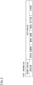
- FIG. 2 is a diagram illustrating an exemplary configuration of the first information.
- the first information includes a header region and a data region.
- the header region stores data indicating a version of the first information.
- the version of the first information is determined in accordance with a model and the like of the control board 5.
- the data region stores data indicating a serial number, a model name, a model setting, and the like of the outdoor unit 4.
- connection unit 13 is a connector to which a cable 7 (to be described later) is connected.
- the connection unit 13 includes a plurality of terminals (five terminals 131, 132, 133, 134, and 135 in this embodiment).
- the terminal 131 is a power supply terminal configured to receive electric power.
- the terminal 132 is a transmission terminal capable of transmitting the first information and the like.
- the terminal 133 is a reception terminal capable of receiving the first information and the like.
- the terminal 134 is an input terminal to which a first signal (to be described later) is input.
- the terminal 135 is a ground terminal that is grounded.
- the control unit 11 is a microcomputer constituted of a central processing unit (CPU) and the like. In a case where the control board 5, on which the control unit 11 is mounted, becomes defective, and the defective control board 5 is replaced with a new control board 5, the control unit 11 is capable of performing first control to transmit the first information to the new control board 5. Details of the first control will be described later.
- control unit 11 is capable of performing second control to receive the first information from the defective control board 5. Details of the second control will be described later.
- the defective control board 5 is referred to as a first board 5A
- the new control board 5 is referred to as a second board 5B (also see FIG. 3 ).
- the control unit 11, the storage unit 12, and the connection unit 13 are respectively referred to as a first control unit 11A, a first storage unit 12A, and a first connection unit 13A.
- the control unit 11, the storage unit 12, and the connection unit 13 are respectively referred to as a second control unit 11B, a second storage unit 12B, and a second connection unit 13B.
- the second storage unit 12B stores empty first information.
- empty means that no data is stored in the data region of the first information, and involves a case where a version is stored in the header region of the first information. In this embodiment, the version is stored in the header region of the empty first information.
- the second storage unit 12B is capable of storing the first information transmitted by the first control from the first board 5A to the second board 5B. Specifically, the second storage unit 12B is capable of copying the data in the data region of the first information transmitted by the first control from the first board 5A to the second board 5B, to the empty data region of the first information stored in the second storage unit 12B.
- the information takeover system 1 further includes the cable 7 configured to connect the first board 5A and the second board 5B to each other in an information exchangeable manner.
- the cable 7 includes a first connector 8 connectable to the first connection unit 13A of the first board 5A, and a second connector 9 connectable to the second connection unit 13B of the second board 5B.
- the first connector 8 includes a plurality of terminals (five terminals 81, 82, 83, 84, and 85 in this embodiment). When the first connector 8 is connected to the first connection unit 13A, the terminals 81, 82, 83, 84, and 85 are respectively connected to the power supply terminal 131, transmission terminal 132, reception terminal 133, input terminal 134, and ground terminal 135 of the first connection unit 13A.
- the second connector 9 includes a plurality of terminals (five terminals 91, 92, 93, 94, and 95 in this embodiment).
- the terminals 91, 92, 93, 94, and 95 are respectively connected to the power supply terminal 131, transmission terminal 132, reception terminal 133, input terminal 134, and ground terminal 135 of the second connection unit 13B.
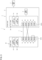
- FIG. 3 is an explanatory diagram illustrating a state in which the first board 5A and the second board 5B are connected to each other with the cable 7.
- the second board 5B is connected with the cable 7 to the first board 5A that remains mounted to the outdoor unit 4.
- the power supply terminal 131 of the first connection unit 13A is electrically connected to the power supply 6, so that the first board 5A receives electric power from the power supply 6.
- the first connector 8 and the second connector 9 of the cable 7 are respectively connected to the first connection unit 13A of the first board 5A and the second connection unit 13B of the second board 5B.
- the terminal 81 of the first connector 8 and the terminal 91 of the second connector 9 are electrically connected to each other.
- the power supply terminal 131 of the second connection unit 13B is electrically connected to the power supply terminal 131 of the first connection unit 13A via the terminals 81 and 91 of the cable 7. With this connection, the second board 5B receives electric power from the first board 5A through the cable 7.
- the terminal 94 and the terminal 95 are electrically connected to each other.
- the input terminal 134 of the second connection unit 13B is electrically connected to the ground terminal 135 of the second connection unit 13B via the terminals 94 and 95 of the second connector 9. Accordingly, when the second connector 9 is connected to the second connection unit 13B, a low-voltage LOW signal (a voltage signal) is automatically output from the terminal 94 of the second connector 9 to the input terminal 134 of the second connection unit 13B.
- the terminal 84 and the terminal 85 are not electrically connected to each other. Therefore, even when the first connector 8 is connected to the first connection unit 13A, the input terminal 134 of the first connection unit 13A is not electrically connected to the ground terminal 135 of the first connection unit 13A. Accordingly, when the first connector 8 is connected to the first connection unit 13A, a high-voltage HIGH signal (a voltage signal) is automatically output from the terminal 84 of the first connector 8 to the input terminal 134 of the first connection unit 13A.
- the first connector 8 and the second connector 9 respectively include the terminal 84 and the terminal 94 from which different signals (e.g., the HIGH signal, the LOW signal) are output.
- the LOW signal output from the terminal 94 of the second connector 9 is used as a first signal serving as a trigger when the first control unit 11A performs the first control.
- the terminal 82 of the first connector 8 is electrically connected to the terminal 93 of the second connector 9.
- the transmission terminal 132 of the first connection unit 13A is electrically connected to the reception terminal 133 of the second connection unit 13B via the terminals 82 and 93 of the cable 7.
- Information can thus be transmitted from the first board 5A to the second board 5B through the cable 7.
- the terminal 92 of the second connector 9 is electrically connected to the terminal 83 of the first connector 8.
- the transmission terminal 132 of the second connection unit 13B is electrically connected to the reception terminal 133 of the first connection unit 13A via the terminals 92 and 83 of the cable 7.
- Information can thus be transmitted from the second board 5B to the first board 5A through the cable 7.
- FIG. 4 is a sequence diagram illustrating exemplary control performed by the first control unit 11A of the first board 5A and exemplary control performed by the second control unit 11B of the second board 5B.
- the first signal (the LOW signal) is input to the second connection unit 13B of the second board 5B as described above.
- the second control unit 11B determines whether the first signal has been received through the second connection unit 13B (step ST1).
- the second control unit 11B when not receiving the first signal ("No" in step ST1), makes a determination in step ST1 again after a lapse of a predetermined time.
- the second control unit 11B when receiving the first signal ("Yes" in step ST1), performs the second control to receive the first information from the first board 5A. Specifically, the second control unit 11B performs the second control to transmit, to the first control unit 11A, a second signal for requesting the first control unit 11A to transmit the first information (step ST2).
- the second signal is transmitted from the transmission terminal 132 of the second connection unit 13B, and then is received at the reception terminal 133 of the first connection unit 13A through the terminals 92 and 83 of the cable 7.
- the first control unit 11A determines whether the second signal has been received through the first connection unit 13A (step ST3).
- the first control unit 11A when not receiving the second signal ("No" in step ST3), makes a determination in step ST3 again after a lapse of a predetermined time.
- the first control unit 11A when receiving the second signal ("Yes" in step ST3), performs the first control to transmit the first information to the second board 5B. Specifically, the first control unit 11A transmits the first information stored in the first storage unit 12A, to the second control unit 11B (step ST4). The first information is transmitted from the transmission terminal 132 of the first connection unit 13A, and then is received at the reception terminal 133 of the second connection unit 13B via the terminals 82 and 93 of the cable 7.
- the second control unit 11B determines whether the first information has been received through the second connection unit 13B (step ST5). The second control unit 11B, when not receiving the first information ("No" in step ST5), terminates the processing.
- the second control unit 11B when receiving the first information ("Yes" in step ST5), determines whether the received first information is empty (step ST6). Specifically, the second control unit 11B determines whether the data capacity in the data region of the received first information is zero. The second control unit 11B, when determining that the received first information is empty ("Yes" in step ST6), terminates the processing without storing the first information in the second storage unit 12B.
- the second control unit 11B when determining that the received first information is not empty ("No" in step ST6), determines whether to store the received first information in the second storage unit 12B, based on the version of the first information. Specifically, the second control unit 11B determines whether the version of the received first information is older than a predetermined version (step ST7). It should be noted that the determination in step ST7 is not limited to that described in this embodiment. For example, the second control unit 11B may determine whether the version of the received first information is older than the version of the first information in the second board 5B.
- the second control unit 11B when determining that the version of the received first information is older than the predetermined version ("Yes" in step ST7), terminates the processing without storing the first information in the second storage unit 12B.
- the second control unit 11B when determining that the version of the received first information is not older than the predetermined version ("No" in step ST7), stores the first information in the second storage unit 12B (step ST8). Specifically, the second control unit 11B copies the data in the data region of the received first information to the empty data region of the first information stored in the second storage unit 12B.
- Takeover of the first information can thus be performed from the first board 5A to the second board 5B.
- the first connector 8 and the second connector 9 of the cable 7 in the state illustrated in FIG. 3 are respectively disconnected from the first connection unit 13A and the second connection unit 13B.
- the first board 5A is removed from the outdoor unit 4, and then the second board 5B is mounted to the outdoor unit 4 as illustrated in FIG. 5 . Replacement of the first board 5A with the second board 5B is thus completed.
- the first board 5A may be removed from the outdoor unit 4 and the second board 5B may be mounted to the outdoor unit 4 as illustrated in FIG. 5 , prior to the takeover of the first information from the first board 5A to the second board 5B.
- the second board 5B mounted to the outdoor unit 4 receives electric power from the power supply 6.
- the first connector 8 of the cable 7 is connected to the first connection unit 13A of the removed first board 5A.
- the second connector 9 of the cable 7 is connected to the second connection unit 13B of the second board 5B mounted to the outdoor unit 4.
- the first board 5A is capable of receiving electric power from the second board 5B through the cable 7.
- the first control unit 11A and the second control unit 11B execute processing (step ST1 to step ST8) similar to that described in the foregoing embodiment.
- Takeover of the first information can thus be performed from the first board 5A to the second board 5B.
- the first connector 8 and the second connector 9 of the cable 7 are respectively disconnected from the first connection unit 13A and the second connection unit 13B. Replacement of the first board 5A with the second board 5B is thus completed.
- the first control unit 11A performs the first control with the first board 5A and the second board 5B connected to each other with the cable 7, thereby transmitting the first information stored in the first storage unit 12A, to the second board 5B.
- This configuration facilitates takeover of the first information about the outdoor unit 4 from the first board 5A to the second board 5B.
- the second control unit 11B of the second board 5B requests the first control unit 11A to transmit the first information when receiving the first signal serving as a trigger for performing the first control with the first board 5A and the second board 5B connected to each other in the information exchangeable manner.
- the first control unit 11A is capable of automatically performing the first control, based on this request.
- the first control unit 11A performs the first control as described above to facilitate transmission of the first information from the first board 5A to the second board 5B.
- the first connector 8 and the second connector 9 of the cable 7 respectively include the terminal 84 and the terminal 94 from which different signals (e.g., the HIGH signal, the LOW signal) are output.
- This configuration allows the second control unit 11B to automatically receive the first signal (the LOW signal) in such a manner that the first board 5A and the second board 5B are connected to each other with the cable 7.
- the second control unit 11B does not store the first information received from the first board 5A in the second storage unit 12B when the version of the received first information is older than the predetermined version. This configuration suppresses the occurrence of malfunction owing to a difference in version.
- the second control unit 11B does not store the first information received from the first board 5A in the second storage unit 12B when the received first information is empty. This configuration suppresses a possibility that the empty first information is stored in the second storage unit 12B of the second board 5B.
- the second board 5B receives electric power from the first board 5A (or the second board 5B) through the cable 7 with the first board 5A (or the second board 5B) electrically connected to the power supply 6 of the outdoor unit 4. According to this configuration, there is no necessity to prepare a dedicated power supply for supplying electric power to the second board 5B (or the first board 5A). This configuration therefore further facilitates takeover of the first information from the first board 5A to the second board 5B.
- FIG. 7 is a schematic configuration diagram of an information takeover system 1 according to a second embodiment.
- a cable 7 is equipped with a battery 20.
- the battery 20 is configured to supply electric power to a first board 5A and a second board 5B with the first board 5A and the second board 5B connected to each other with the cable 7.
- the battery 20 is connected to a terminal 81 of a first connector 8 of the cable 7 and a terminal 91 of a second connector 9 of the cable 7.
- FIG. 8 is an explanatory diagram illustrating a state in which the first board 5A and the second board 5B are connected to each other with the cable 7.
- the first board 5A and the second board 5B are connected to each other with the cable 7 in a state in which neither the first board 5A nor the second board 5B is mounted to an outdoor unit 4.
- the terminal 81 of the first connector 8, which is connected to the battery 20 is connected to a power supply terminal 131 of a first connection unit 13A.
- the terminal 91 of the second connector 9, which is connected to the battery 20, is connected to a power supply terminal 131 of a second connection unit 13B.
- Each of the first board 5A and the second board 5B is thus capable of receiving electric power from the battery 20 through the cable 7.
- the first control unit 11A and the second control unit 11B execute processing (step ST1 to step ST8) similar to that described in the foregoing embodiment.
- Other configurations of this embodiment are similar to those of the first embodiment. Therefore, these configurations are denoted with reference signs identical with those of the similar configurations, and the detailed description thereof will not be given here.
- the first control unit 11A performs first control with the first board 5A and the second board 5B connected to each other with the cable 7, thereby transmitting first information stored in a first storage unit 12A, to the second board 5B.
- This configuration facilitates takeover of the first information about the outdoor unit 4 from the first board 5A to the second board 5B.
- This configuration also enables supply of electric power from the battery 20 on the cable 7 to each of the first board 5A and the second board 5B in such a manner that the first board 5A and the second board 5B are connected to each other with the cable 7.
- This configuration enables takeover of the first information from the first board 5A to the second board 5B even at a place distant from the outdoor unit 4.
- the information takeover system is designed to take over the first information about the outdoor unit 4, but may be applied to a case of taking over first information about another component (e.g., the indoor unit 3) of the air conditioning apparatus 2.
- the second control unit 11B receives the first signal serving as a trigger for performing the first control.
- the first control unit 11A may alternatively receive the first signal.
- the first control unit 11A is preferably configured to perform, when receiving the first signal, first control to transmit the first information to the second board 5B.
- the first control is performed based on reception of the first signal through the cable 7; however, the first control is not necessarily performed based on the reception of the first signal.
- the second control unit 11B may determine whether the first information stored in the second storage unit 12B is empty, and may request the first control unit 11A to perform the first control when the first information is empty.
Landscapes
- Engineering & Computer Science (AREA)
- Chemical & Material Sciences (AREA)
- Combustion & Propulsion (AREA)
- Mechanical Engineering (AREA)
- General Engineering & Computer Science (AREA)
- Human Computer Interaction (AREA)
- Air Conditioning Control Device (AREA)
- Selective Calling Equipment (AREA)
Applications Claiming Priority (3)
| Application Number | Priority Date | Filing Date | Title |
|---|---|---|---|
| JP2020214611A JP7116338B2 (ja) | 2020-12-24 | 2020-12-24 | 情報引き継ぎシステム、第2基板、空気調和装置、及び情報引き継ぎ方法 |
| PCT/JP2021/044528 WO2022138077A1 (ja) | 2020-12-24 | 2021-12-03 | 情報引き継ぎシステム、第2基板、空気調和装置、及び情報引き継ぎ方法 |
| EP21910229.0A EP4269891B8 (de) | 2020-12-24 | 2021-12-03 | Informationsübernahmesystem und informationsübernahmeverfahren |
Related Parent Applications (2)
| Application Number | Title | Priority Date | Filing Date |
|---|---|---|---|
| EP21910229.0A Division-Into EP4269891B8 (de) | 2020-12-24 | 2021-12-03 | Informationsübernahmesystem und informationsübernahmeverfahren |
| EP21910229.0A Division EP4269891B8 (de) | 2020-12-24 | 2021-12-03 | Informationsübernahmesystem und informationsübernahmeverfahren |
Publications (3)
| Publication Number | Publication Date |
|---|---|
| EP4471346A2 true EP4471346A2 (de) | 2024-12-04 |
| EP4471346A3 EP4471346A3 (de) | 2025-02-26 |
| EP4471346B1 EP4471346B1 (de) | 2025-10-15 |
Family
ID=82159502
Family Applications (2)
| Application Number | Title | Priority Date | Filing Date |
|---|---|---|---|
| EP21910229.0A Active EP4269891B8 (de) | 2020-12-24 | 2021-12-03 | Informationsübernahmesystem und informationsübernahmeverfahren |
| EP24206086.1A Active EP4471346B1 (de) | 2020-12-24 | 2021-12-03 | Informationsübernahmesystem und informationsübernahmeverfahren |
Family Applications Before (1)
| Application Number | Title | Priority Date | Filing Date |
|---|---|---|---|
| EP21910229.0A Active EP4269891B8 (de) | 2020-12-24 | 2021-12-03 | Informationsübernahmesystem und informationsübernahmeverfahren |
Country Status (5)
| Country | Link |
|---|---|
| US (1) | US11953219B2 (de) |
| EP (2) | EP4269891B8 (de) |
| JP (1) | JP7116338B2 (de) |
| CN (1) | CN116670441B (de) |
| WO (1) | WO2022138077A1 (de) |
Families Citing this family (1)
| Publication number | Priority date | Publication date | Assignee | Title |
|---|---|---|---|---|
| US12510263B2 (en) * | 2019-01-15 | 2025-12-30 | Hisense (Guangdong) Air Conditioning Co., Ltd. | Air conditioner |
Citations (1)
| Publication number | Priority date | Publication date | Assignee | Title |
|---|---|---|---|---|
| JP2007318572A (ja) | 2006-05-26 | 2007-12-06 | Max Co Ltd | 電子機器 |
Family Cites Families (32)
| Publication number | Priority date | Publication date | Assignee | Title |
|---|---|---|---|---|
| EP0011119A1 (de) * | 1978-10-12 | 1980-05-28 | WLW-Elektrotechnik GmbH & Co. KG | Anzeige- und Bedienungselement |
| JP2799809B2 (ja) * | 1993-02-16 | 1998-09-21 | 株式会社日立製作所 | 空調管理システム |
| JP3109448B2 (ja) * | 1997-04-25 | 2000-11-13 | ダイキン工業株式会社 | 伝送システム |
| CN1290328A (zh) * | 1997-10-28 | 2001-04-04 | 科尔特克工业公司 | 压缩机系统以及用于控制压缩机系统的方法 |
| EP1121245B1 (de) * | 1998-06-18 | 2008-12-24 | Kline & Walker L.L.C. | Automatische vorrichtung zur überwachung von auf abstand zu bedienende ausrüstungen und maschinen weltweit anwendbar |
| US6489742B2 (en) * | 2000-12-26 | 2002-12-03 | John Lumsden | Efficiency maximizing motor controller and method |
| KR100626443B1 (ko) * | 2003-11-24 | 2006-09-20 | 엘지전자 주식회사 | 공기조화기의 실내기 |
| KR20060059031A (ko) * | 2004-11-26 | 2006-06-01 | 엘지전자 주식회사 | 공기 조화기의 상태를 모니터링하는 장치 |
| JP3806882B2 (ja) * | 2004-11-29 | 2006-08-09 | ダイキン工業株式会社 | 空気調和機 |
| CN1896627A (zh) * | 2005-07-15 | 2007-01-17 | 乐金电子(天津)电器有限公司 | 空气调节器的遥控器及其运行方法 |
| JP2008122027A (ja) * | 2006-11-15 | 2008-05-29 | Matsushita Electric Ind Co Ltd | 空気調和機 |
| US8117862B2 (en) * | 2007-03-13 | 2012-02-21 | Trane International Inc. | Device and method for recording air conditioning system information |
| JP5204432B2 (ja) | 2007-07-10 | 2013-06-05 | 東芝キヤリア株式会社 | 電気機器、電気機器のサービス方法 |
| JP2010152641A (ja) | 2008-12-25 | 2010-07-08 | Mitsubishi Electric Corp | データ書換システム |
| US8742814B2 (en) * | 2009-07-15 | 2014-06-03 | Yehuda Binder | Sequentially operated modules |
| US9999717B2 (en) * | 2011-05-24 | 2018-06-19 | Deka Products Limited Partnership | Systems and methods for detecting vascular access disconnection |
| JP5832366B2 (ja) * | 2012-05-02 | 2015-12-16 | 三菱電機株式会社 | 空気調和機 |
| JP2013238340A (ja) | 2012-05-15 | 2013-11-28 | Mitsubishi Electric Corp | 空気調和機 |
| JP5382169B1 (ja) | 2012-07-06 | 2014-01-08 | ダイキン工業株式会社 | 空調管理システム |
| JP6021768B2 (ja) * | 2013-09-09 | 2016-11-09 | 三菱電機株式会社 | 空調システム |
| US9535724B2 (en) * | 2014-04-16 | 2017-01-03 | Komatsu Ltd. | Information processor for work machine, work machine, and information processing method for work machine |
| US9982904B2 (en) * | 2014-11-07 | 2018-05-29 | Daikin Industries, Ltd. | Air conditioning system |
| CN109690201B (zh) * | 2016-09-23 | 2021-03-12 | 三菱电机株式会社 | 空调机 |
| CN110325929B (zh) * | 2016-12-07 | 2021-05-25 | 阿瑞路资讯安全科技股份有限公司 | 用于检测有线网络变化的信号波形分析的系统和方法 |
| JP6818773B2 (ja) * | 2017-02-07 | 2021-01-20 | 三菱電機株式会社 | 空気調和装置 |
| CN107332743A (zh) * | 2017-06-08 | 2017-11-07 | 青岛海信日立空调系统有限公司 | 一种更新家电设备的配置信息的方法及装置 |
| JPWO2019244389A1 (ja) | 2018-06-19 | 2021-06-24 | シャープ株式会社 | 空気調和機 |
| JP7161899B2 (ja) | 2018-09-21 | 2022-10-27 | リンナイ株式会社 | 通信システム |
| CN121815842A (zh) * | 2019-01-29 | 2026-04-07 | 奥斯兰姆奥普托半导体股份有限两合公司 | 微型发光二极管、微型发光二极管装置、显示器及其方法 |
| US11287406B2 (en) * | 2019-04-15 | 2022-03-29 | Mustang Sampling, Llc | Multi-input auto-switching gas sample conditioning system |
| JP7476583B2 (ja) * | 2020-03-11 | 2024-05-01 | 株式会社デンソー | 測定装置 |
| JP7650169B2 (ja) * | 2021-03-09 | 2025-03-24 | Tdk株式会社 | 分波器 |
-
2020
- 2020-12-24 JP JP2020214611A patent/JP7116338B2/ja active Active
-
2021
- 2021-12-03 CN CN202180086966.XA patent/CN116670441B/zh active Active
- 2021-12-03 EP EP21910229.0A patent/EP4269891B8/de active Active
- 2021-12-03 EP EP24206086.1A patent/EP4471346B1/de active Active
- 2021-12-03 WO PCT/JP2021/044528 patent/WO2022138077A1/ja not_active Ceased
-
2023
- 2023-06-07 US US18/206,706 patent/US11953219B2/en active Active
Patent Citations (1)
| Publication number | Priority date | Publication date | Assignee | Title |
|---|---|---|---|---|
| JP2007318572A (ja) | 2006-05-26 | 2007-12-06 | Max Co Ltd | 電子機器 |
Also Published As
| Publication number | Publication date |
|---|---|
| WO2022138077A1 (ja) | 2022-06-30 |
| EP4269891A4 (de) | 2024-06-19 |
| EP4269891B1 (de) | 2025-04-16 |
| EP4269891B8 (de) | 2025-07-09 |
| EP4269891A1 (de) | 2023-11-01 |
| EP4471346A3 (de) | 2025-02-26 |
| JP2022100563A (ja) | 2022-07-06 |
| CN116670441B (zh) | 2024-02-20 |
| JP7116338B2 (ja) | 2022-08-10 |
| EP4471346B1 (de) | 2025-10-15 |
| US11953219B2 (en) | 2024-04-09 |
| US20230314028A1 (en) | 2023-10-05 |
| CN116670441A (zh) | 2023-08-29 |
Similar Documents
| Publication | Publication Date | Title |
|---|---|---|
| US9599359B2 (en) | Integrated controller an HVAC system | |
| CN113865024B (zh) | 中央空调远程升级系统 | |
| EP2479625B1 (de) | Klimaanlage, Verfahren zur Steuerung von Außeneinheiten davon, und zentrales Steuerungssystem damit | |
| US20100298985A1 (en) | Customer equipment profile system for hvac controls | |
| USRE43677E1 (en) | Apparatus for restoring network information for home network system and method thereof | |
| EP3726157A1 (de) | Klimaanlage, fernsteuerungsvorrichtung und verfahren zur einsparung der betriebsdatenhistorie einer klimaanlage | |
| US20110145395A1 (en) | Air conditioning system | |
| US11953219B2 (en) | Takeover system for an air conditioning apparatus to transmit information from a first board to a second board | |
| EP2584277B1 (de) | Mit Klimaanlage ausgerüstetes Netzwerksystem und Steuerungsverfahren davon | |
| US9464835B2 (en) | Remote software loading for refrigerant system | |
| EP3541012B1 (de) | Kommunikationsvorrichtung, kommunikationssystem, kommunikationsverfahren und programm dafür | |
| CN118585499A (zh) | 储能管理系统更新方法、装置以及存储介质 | |
| US6701430B1 (en) | Communication system, communication initialization apparatus and program storage medium | |
| WO2023282079A1 (ja) | システムおよび方法 | |
| EP4550243A1 (de) | Servervorrichtung, kältekreislaufsystem, verwaltungsverfahren und verwaltungsprogramm | |
| EP1818818B1 (de) | Datenverarbeitungsgerät und Verfahren zur Einstellung von Programmdaten | |
| CN115289626B (zh) | 一种多联机空调系统 | |
| JP7817610B1 (ja) | 中継装置、および中継プログラム | |
| JPH02272252A (ja) | 空気調和装置の運転制御装置 | |
| JP3864909B2 (ja) | 冷凍装置の制御プログラムの書き換え方法 | |
| CN117928058A (zh) | 一种空调模块机机组通讯控制的方法 | |
| CN115742664A (zh) | 一种用于热泵的控制方法、装置及相关设备 | |
| JP2001174033A (ja) | 空気調和機の制御装置 | |
| JP2003345433A (ja) | 設備機器制御システムおよび設備機器制御装置。 |
Legal Events
| Date | Code | Title | Description |
|---|---|---|---|
| PUAI | Public reference made under article 153(3) epc to a published international application that has entered the european phase |
Free format text: ORIGINAL CODE: 0009012 |
|
| STAA | Information on the status of an ep patent application or granted ep patent |
Free format text: STATUS: REQUEST FOR EXAMINATION WAS MADE |
|
| 17P | Request for examination filed |
Effective date: 20241011 |
|
| AC | Divisional application: reference to earlier application |
Ref document number: 4269891 Country of ref document: EP Kind code of ref document: P |
|
| AK | Designated contracting states |
Kind code of ref document: A2 Designated state(s): AL AT BE BG CH CY CZ DE DK EE ES FI FR GB GR HR HU IE IS IT LI LT LU LV MC MK MT NL NO PL PT RO RS SE SI SK SM TR |
|
| RAP3 | Party data changed (applicant data changed or rights of an application transferred) |
Owner name: DAIKIN INDUSTRIES, LTD. |
|
| REG | Reference to a national code |
Ref country code: DE Ref legal event code: R079 Free format text: PREVIOUS MAIN CLASS: F24F0011880000 Ipc: F24F0011320000 Ref country code: DE Ref legal event code: R079 Ref document number: 602021040687 Country of ref document: DE Free format text: PREVIOUS MAIN CLASS: F24F0011880000 Ipc: F24F0011320000 |
|
| PUAL | Search report despatched |
Free format text: ORIGINAL CODE: 0009013 |
|
| P01 | Opt-out of the competence of the unified patent court (upc) registered |
Free format text: CASE NUMBER: APP_1124/2025 Effective date: 20250108 |
|
| AK | Designated contracting states |
Kind code of ref document: A3 Designated state(s): AL AT BE BG CH CY CZ DE DK EE ES FI FR GB GR HR HU IE IS IT LI LT LU LV MC MK MT NL NO PL PT RO RS SE SI SK SM TR |
|
| RIC1 | Information provided on ipc code assigned before grant |
Ipc: F24F 11/88 20180101ALI20250120BHEP Ipc: F24F 11/64 20180101ALI20250120BHEP Ipc: F24F 11/63 20180101ALI20250120BHEP Ipc: F24F 11/49 20180101ALI20250120BHEP Ipc: F24F 11/32 20180101AFI20250120BHEP |
|
| REG | Reference to a national code |
Ref country code: DE Ref legal event code: R079 Free format text: PREVIOUS MAIN CLASS: F24F0011320000 Ipc: F24F0011300000 Ref country code: DE Ref legal event code: R079 Ref document number: 602021040687 Country of ref document: DE Free format text: PREVIOUS MAIN CLASS: F24F0011320000 Ipc: F24F0011300000 |
|
| RIC1 | Information provided on ipc code assigned before grant |
Ipc: F24F 11/64 20180101ALI20250428BHEP Ipc: F24F 11/88 20180101ALI20250428BHEP Ipc: F24F 11/63 20180101ALI20250428BHEP Ipc: F24F 11/49 20180101ALI20250428BHEP Ipc: F24F 11/32 20180101ALI20250428BHEP Ipc: F24F 11/30 20180101AFI20250428BHEP |
|
| GRAP | Despatch of communication of intention to grant a patent |
Free format text: ORIGINAL CODE: EPIDOSNIGR1 |
|
| STAA | Information on the status of an ep patent application or granted ep patent |
Free format text: STATUS: GRANT OF PATENT IS INTENDED |
|
| INTG | Intention to grant announced |
Effective date: 20250626 |
|
| GRAS | Grant fee paid |
Free format text: ORIGINAL CODE: EPIDOSNIGR3 |
|
| GRAA | (expected) grant |
Free format text: ORIGINAL CODE: 0009210 |
|
| STAA | Information on the status of an ep patent application or granted ep patent |
Free format text: STATUS: THE PATENT HAS BEEN GRANTED |
|
| AC | Divisional application: reference to earlier application |
Ref document number: 4269891 Country of ref document: EP Kind code of ref document: P |
|
| AK | Designated contracting states |
Kind code of ref document: B1 Designated state(s): AL AT BE BG CH CY CZ DE DK EE ES FI FR GB GR HR HU IE IS IT LI LT LU LV MC MK MT NL NO PL PT RO RS SE SI SK SM TR |
|
| REG | Reference to a national code |
Ref country code: GB Ref legal event code: FG4D Ref country code: CH Ref legal event code: F10 Free format text: ST27 STATUS EVENT CODE: U-0-0-F10-F00 (AS PROVIDED BY THE NATIONAL OFFICE) Effective date: 20251015 |
|
| REG | Reference to a national code |
Ref country code: DE Ref legal event code: R096 Ref document number: 602021040687 Country of ref document: DE |
|
| REG | Reference to a national code |
Ref country code: IE Ref legal event code: FG4D |
|
| PGFP | Annual fee paid to national office [announced via postgrant information from national office to epo] |
Ref country code: DE Payment date: 20251211 Year of fee payment: 5 |
|
| PGFP | Annual fee paid to national office [announced via postgrant information from national office to epo] |
Ref country code: GB Payment date: 20251219 Year of fee payment: 5 |
|
| PGFP | Annual fee paid to national office [announced via postgrant information from national office to epo] |
Ref country code: AT Payment date: 20260113 Year of fee payment: 5 |
|
| PGFP | Annual fee paid to national office [announced via postgrant information from national office to epo] |
Ref country code: FR Payment date: 20251229 Year of fee payment: 5 |
|
| REG | Reference to a national code |
Ref country code: NL Ref legal event code: MP Effective date: 20251015 |
|
| REG | Reference to a national code |
Ref country code: AT Ref legal event code: MK05 Ref document number: 1847257 Country of ref document: AT Kind code of ref document: T Effective date: 20251015 |
|
| PG25 | Lapsed in a contracting state [announced via postgrant information from national office to epo] |
Ref country code: NL Free format text: LAPSE BECAUSE OF FAILURE TO SUBMIT A TRANSLATION OF THE DESCRIPTION OR TO PAY THE FEE WITHIN THE PRESCRIBED TIME-LIMIT Effective date: 20251015 |
|
| PG25 | Lapsed in a contracting state [announced via postgrant information from national office to epo] |
Ref country code: ES Free format text: LAPSE BECAUSE OF FAILURE TO SUBMIT A TRANSLATION OF THE DESCRIPTION OR TO PAY THE FEE WITHIN THE PRESCRIBED TIME-LIMIT Effective date: 20251015 |
|
| REG | Reference to a national code |
Ref country code: LT Ref legal event code: MG9D |
|
| PG25 | Lapsed in a contracting state [announced via postgrant information from national office to epo] |
Ref country code: NO Free format text: LAPSE BECAUSE OF FAILURE TO SUBMIT A TRANSLATION OF THE DESCRIPTION OR TO PAY THE FEE WITHIN THE PRESCRIBED TIME-LIMIT Effective date: 20260115 |
|
| PG25 | Lapsed in a contracting state [announced via postgrant information from national office to epo] |
Ref country code: AT Free format text: LAPSE BECAUSE OF FAILURE TO SUBMIT A TRANSLATION OF THE DESCRIPTION OR TO PAY THE FEE WITHIN THE PRESCRIBED TIME-LIMIT Effective date: 20251015 Ref country code: FI Free format text: LAPSE BECAUSE OF FAILURE TO SUBMIT A TRANSLATION OF THE DESCRIPTION OR TO PAY THE FEE WITHIN THE PRESCRIBED TIME-LIMIT Effective date: 20251015 Ref country code: HR Free format text: LAPSE BECAUSE OF FAILURE TO SUBMIT A TRANSLATION OF THE DESCRIPTION OR TO PAY THE FEE WITHIN THE PRESCRIBED TIME-LIMIT Effective date: 20251015 |
|
| PG25 | Lapsed in a contracting state [announced via postgrant information from national office to epo] |
Ref country code: RS Free format text: LAPSE BECAUSE OF FAILURE TO SUBMIT A TRANSLATION OF THE DESCRIPTION OR TO PAY THE FEE WITHIN THE PRESCRIBED TIME-LIMIT Effective date: 20260115 |
|
| PG25 | Lapsed in a contracting state [announced via postgrant information from national office to epo] |
Ref country code: IS Free format text: LAPSE BECAUSE OF FAILURE TO SUBMIT A TRANSLATION OF THE DESCRIPTION OR TO PAY THE FEE WITHIN THE PRESCRIBED TIME-LIMIT Effective date: 20260215 |
|
| PG25 | Lapsed in a contracting state [announced via postgrant information from national office to epo] |
Ref country code: PT Free format text: LAPSE BECAUSE OF FAILURE TO SUBMIT A TRANSLATION OF THE DESCRIPTION OR TO PAY THE FEE WITHIN THE PRESCRIBED TIME-LIMIT Effective date: 20260216 |
|
| PG25 | Lapsed in a contracting state [announced via postgrant information from national office to epo] |
Ref country code: PL Free format text: LAPSE BECAUSE OF FAILURE TO SUBMIT A TRANSLATION OF THE DESCRIPTION OR TO PAY THE FEE WITHIN THE PRESCRIBED TIME-LIMIT Effective date: 20251015 |
|
| PG25 | Lapsed in a contracting state [announced via postgrant information from national office to epo] |
Ref country code: LV Free format text: LAPSE BECAUSE OF FAILURE TO SUBMIT A TRANSLATION OF THE DESCRIPTION OR TO PAY THE FEE WITHIN THE PRESCRIBED TIME-LIMIT Effective date: 20251015 |
|
| PG25 | Lapsed in a contracting state [announced via postgrant information from national office to epo] |
Ref country code: BG Free format text: LAPSE BECAUSE OF FAILURE TO SUBMIT A TRANSLATION OF THE DESCRIPTION OR TO PAY THE FEE WITHIN THE PRESCRIBED TIME-LIMIT Effective date: 20251015 |