EP4470697A1 - Schneidwerkzeug - Google Patents
Schneidwerkzeug Download PDFInfo
- Publication number
- EP4470697A1 EP4470697A1 EP22923804.3A EP22923804A EP4470697A1 EP 4470697 A1 EP4470697 A1 EP 4470697A1 EP 22923804 A EP22923804 A EP 22923804A EP 4470697 A1 EP4470697 A1 EP 4470697A1
- Authority
- EP
- European Patent Office
- Prior art keywords
- blade
- radial direction
- attachment screw
- piece
- cutting tool
- Prior art date
- Legal status (The legal status is an assumption and is not a legal conclusion. Google has not performed a legal analysis and makes no representation as to the accuracy of the status listed.)
- Pending
Links
- 238000005520 cutting process Methods 0.000 title claims abstract description 181
- 230000002093 peripheral effect Effects 0.000 claims abstract description 13
- 238000005259 measurement Methods 0.000 description 13
- 238000000034 method Methods 0.000 description 12
- 238000010586 diagram Methods 0.000 description 8
- 238000012360 testing method Methods 0.000 description 8
- 230000000694 effects Effects 0.000 description 3
- 238000011156 evaluation Methods 0.000 description 3
- 239000000463 material Substances 0.000 description 3
- 230000000052 comparative effect Effects 0.000 description 2
- 230000007246 mechanism Effects 0.000 description 2
- 230000000087 stabilizing effect Effects 0.000 description 2
- 229910052582 BN Inorganic materials 0.000 description 1
- PZNSFCLAULLKQX-UHFFFAOYSA-N Boron nitride Chemical compound N#B PZNSFCLAULLKQX-UHFFFAOYSA-N 0.000 description 1
- 229910000831 Steel Inorganic materials 0.000 description 1
- 238000005219 brazing Methods 0.000 description 1
- 230000008859 change Effects 0.000 description 1
- 239000000470 constituent Substances 0.000 description 1
- 229910003460 diamond Inorganic materials 0.000 description 1
- 239000010432 diamond Substances 0.000 description 1
- 238000006073 displacement reaction Methods 0.000 description 1
- 230000006872 improvement Effects 0.000 description 1
- 238000012986 modification Methods 0.000 description 1
- 230000004048 modification Effects 0.000 description 1
- 230000004044 response Effects 0.000 description 1
- 239000010959 steel Substances 0.000 description 1
Images


Classifications
-
- B—PERFORMING OPERATIONS; TRANSPORTING
- B23—MACHINE TOOLS; METAL-WORKING NOT OTHERWISE PROVIDED FOR
- B23C—MILLING
- B23C5/00—Milling-cutters
- B23C5/16—Milling-cutters characterised by physical features other than shape
- B23C5/20—Milling-cutters characterised by physical features other than shape with removable cutter bits or teeth or cutting inserts
- B23C5/22—Securing arrangements for bits or teeth or cutting inserts
- B23C5/24—Securing arrangements for bits or teeth or cutting inserts adjustable
-
- B—PERFORMING OPERATIONS; TRANSPORTING
- B23—MACHINE TOOLS; METAL-WORKING NOT OTHERWISE PROVIDED FOR
- B23C—MILLING
- B23C5/00—Milling-cutters
- B23C5/02—Milling-cutters characterised by the shape of the cutter
- B23C5/06—Face-milling cutters, i.e. having only or primarily a substantially flat cutting surface
-
- B—PERFORMING OPERATIONS; TRANSPORTING
- B23—MACHINE TOOLS; METAL-WORKING NOT OTHERWISE PROVIDED FOR
- B23C—MILLING
- B23C5/00—Milling-cutters
- B23C5/16—Milling-cutters characterised by physical features other than shape
- B23C5/20—Milling-cutters characterised by physical features other than shape with removable cutter bits or teeth or cutting inserts
- B23C5/22—Securing arrangements for bits or teeth or cutting inserts
- B23C5/2204—Securing arrangements for bits or teeth or cutting inserts with cutting inserts clamped against the walls of the recess in the cutter body by a clamping member acting upon the wall of a hole in the insert
- B23C5/2226—Securing arrangements for bits or teeth or cutting inserts with cutting inserts clamped against the walls of the recess in the cutter body by a clamping member acting upon the wall of a hole in the insert for plate-like cutting inserts fitted on an intermediate carrier, e.g. shank fixed in the cutter body
-
- B—PERFORMING OPERATIONS; TRANSPORTING
- B23—MACHINE TOOLS; METAL-WORKING NOT OTHERWISE PROVIDED FOR
- B23B—TURNING; BORING
- B23B27/00—Tools for turning or boring machines; Tools of a similar kind in general; Accessories therefor
- B23B27/14—Cutting tools of which the bits or tips or cutting inserts are of special material
- B23B27/16—Cutting tools of which the bits or tips or cutting inserts are of special material with exchangeable cutting bits or cutting inserts, e.g. able to be clamped
- B23B27/1603—Cutting tools of which the bits or tips or cutting inserts are of special material with exchangeable cutting bits or cutting inserts, e.g. able to be clamped with specially shaped plate-like exchangeable cutting inserts, e.g. chip-breaking groove
- B23B27/1611—Cutting tools of which the bits or tips or cutting inserts are of special material with exchangeable cutting bits or cutting inserts, e.g. able to be clamped with specially shaped plate-like exchangeable cutting inserts, e.g. chip-breaking groove characterised by having a special shape
-
- B—PERFORMING OPERATIONS; TRANSPORTING
- B23—MACHINE TOOLS; METAL-WORKING NOT OTHERWISE PROVIDED FOR
- B23C—MILLING
- B23C5/00—Milling-cutters
- B23C5/16—Milling-cutters characterised by physical features other than shape
- B23C5/20—Milling-cutters characterised by physical features other than shape with removable cutter bits or teeth or cutting inserts
- B23C5/22—Securing arrangements for bits or teeth or cutting inserts
- B23C5/24—Securing arrangements for bits or teeth or cutting inserts adjustable
- B23C5/2462—Securing arrangements for bits or teeth or cutting inserts adjustable the adjusting means being oblique surfaces
-
- B—PERFORMING OPERATIONS; TRANSPORTING
- B23—MACHINE TOOLS; METAL-WORKING NOT OTHERWISE PROVIDED FOR
- B23C—MILLING
- B23C5/00—Milling-cutters
- B23C5/16—Milling-cutters characterised by physical features other than shape
- B23C5/20—Milling-cutters characterised by physical features other than shape with removable cutter bits or teeth or cutting inserts
- B23C5/22—Securing arrangements for bits or teeth or cutting inserts
- B23C5/24—Securing arrangements for bits or teeth or cutting inserts adjustable
- B23C5/2472—Securing arrangements for bits or teeth or cutting inserts adjustable the adjusting means being screws
Definitions
- the present disclosure relates to a cutting tool.
- Japanese Patent Laying-Open No. 2013-176827 (PTL 1) describes a cutting tool.
- the cutting tool described in PTL 1 includes a tool main body, a cartridge, a cutting insert, and a vibration adjustment mechanism.
- the cutting insert is attached to the cartridge.
- the cartridge is attached to the tool main body.
- the vibration adjustment mechanism adjusts an amount of protrusion of a cutting edge of the cutting insert in a radial direction.
- a cutting tool of the present disclosure is rotatable about a central axis and has a front end in an axial direction along the central axis.
- the cutting tool includes a body, a blade, a first attachment screw, an adjustment piece, and a second attachment screw.
- the body has an outer peripheral surface.
- a pocket is formed in the outer peripheral surface at an end portion on the front end side.
- the blade is attached to the body by screwing the first attachment screw into the body in the pocket.
- the blade has a blade side surface facing inward in a radial direction that is orthogonal to the axial direction and that passes through the central axis.
- An inner wall surface of the pocket has a contact surface facing the blade side surface with a space being interposed between the blade side surface and the contact surface in the radial direction.
- the space between the blade side surface and the contact surface is smaller in a direction away from the front end in the axial direction.
- the adjustment piece is disposed between the blade side surface and the contact surface.
- the second attachment screw is screwed into the body and is advanced or retracted along the axial direction so as to move the adjustment piece along the axial direction.
- the present disclosure provides a cutting tool to improve precision in position adjustment of a cutting edge.
- the precision in the position adjustment of the cutting edge can be improved.
- cutting tool 100 A cutting tool according to an embodiment will be referred to as "cutting tool 100".
- a configuration of cutting tool 100 will be described below.
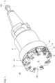
- Fig. 1 is a perspective view of cutting tool 100.
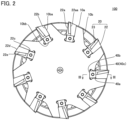
- Fig. 2 is a front view of cutting tool 100.
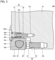
- Fig. 3 is a cross sectional view at III-III in Fig. 2 .
- Fig. 4 is a perspective view of a blade 20.
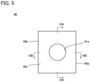
- Fig. 5 is a front view of an adjustment piece 40.
- Fig. 6A is a cross sectional view at VIA-VIA in Fig. 5 .
- Fig. 6B is a cross sectional view at VIB-VIB in Fig. 5 .
- Fig. 6C is a first perspective view of adjustment piece 40.
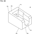
- Fig. 6D is a second perspective view of adjustment piece 40.
- Fig. 6D is a perspective view of adjustment piece 40 when viewed in a direction different from that in Fig. 6C .
- cutting tool 100 is a boring quill.
- cutting tool 100 is not limited thereto.
- the central axis of cutting tool 100 is defined as a central axis A.
- a direction along central axis A is defined as an axial direction.
- a direction orthogonal to the axial direction and passing through central axis A is defined as a radial direction.
- a direction along a circumference centered on central axis A is defined as a peripheral direction.
- Cutting tool 100 has a front end 100a and a base end 100b. Front end 100a and base end 100b are respective ends of cutting tool 100 in the axial direction. Base end 100b is an end opposite to front end 100a. Cutting tool 100 is attached to a main shaft of a machine tool on the base end 100b side. The machine tool rotates cutting tool 100 about central axis A. Cutting tool 100 has a body 10, blade 20, a first attachment screw 30, adjustment piece 40, a second attachment screw 50, and an adjustment screw 60.
- Body 10 is composed of, for example, steel.
- Body 10 has an outer peripheral surface 10a.
- a plurality of pockets 10b are formed in outer peripheral surface 10a at an end portion of body 10 on the front end 100a side.
- the plurality of pockets 10b are formed, for example, at equal intervals in the peripheral direction.
- Each of pockets 10b has a seating surface 10ba and a contact surface 10bb.
- Seating surface 10ba is a portion of an inner wall surface of pocket 10b in contact with a bottom surface 22b described later.
- Contact surface 10bb is a portion of pocket 10b facing a below-described first blade side surface 22c with a space being interposed therebetween in the radial direction in a state in which blade 20 is attached to body 10.
- a screw hole is formed in seating surface 10ba.
- Blade 20 has a cutting edge 21.
- cutting edge 21 When cutting edge 21 is brought into contact with a workpiece with cutting tool 100 being rotated about central axis A, a cutting process on the workpiece is performed.
- Cutting edge 21 has a first cutting edge 21a, a second cutting edge 21b, and a corner cutting edge 21c. First cutting edge 21a and second cutting edge 21b are connected to each other by corner cutting edge 21c. First cutting edge 21a extends along the axial direction when attached to body 10. Second cutting edge 21b extends along the radial direction when attached to body 10. Blade 20 has a base body 22 and a cutting edge tip 23. It should be noted that blade 20 may be constituted only of base body 22.
- Base body 22 is composed of, for example, a cemented carbide.
- Base body 22 has an upper surface 22a, a bottom surface 22b, a first blade side surface 22c, a second blade side surface 22d, a third blade side surface 22e, and a fourth blade side surface 22f.
- Upper surface 22a and bottom surface 22b are end surfaces in the thickness direction of base body 22.
- Bottom surface 22b is a surface opposite to upper surface 22a.
- first blade side surface 22c, second blade side surface 22d, third blade side surface 22e, and fourth blade side surface 22f is contiguous to upper surface 22a at the upper end, and is contiguous to bottom surface 22b at the lower end.
- First blade side surface 22c faces inward in the radial direction when attached to body 10.
- Second blade side surface 22d is a surface opposite to first blade side surface 22c.
- Third blade side surface 22e faces the front end 100a side when attached to body 10.
- Fourth blade side surface 22f is a surface opposite to third blade side surface 22e.
- Upper surface 22a has an attachment surface 22aa.
- Attachment surface 22aa is located at an end portion of upper surface 22a on the third blade side surface 22e side.
- a distance between attachment surface 22aa and bottom surface 22b is smaller than a distance between a portion of upper surface 22a other than attachment surface 22aa and bottom surface 22b.
- a step is formed between attachment surface 22aa and the portion of upper surface 22a other than attachment surface 22aa.
- a through hole 22g is formed in base body 22.
- Through hole 22g extends through base body 22 along the thickness direction. From another viewpoint, it can be said that through hole 22g is opened at upper surface 22a and bottom surface 22b.
- first blade side surface 22c faces contact surface 10bb with a space being interposed therebetween in the radial direction. The space between first blade side surface 22c and contact surface 10bb is smaller in a direction away from front end 100a.
- Cutting edge tip 23 is composed of, for example, a sintered material of cubic boron nitride grains. Cutting edge tip 23 may be composed of a sintered material of diamond grains. However, the constituent material of cutting edge tip 23 is not limited thereto. Cutting edge tip 23 is attached to base body 22. More specifically, cutting edge tip 23 is attached to attachment surface 22aa by brazing, for example. Cutting edge 21 is formed in cutting edge tip 23. It should be noted that when blade 20 does not have cutting edge tip 23, cutting edge 21 is formed in base body 22.
- First attachment screw 30 is used to attach blade 20 to body 10. More specifically, blade 20 is attached to body 10 in pocket 10b by inserting first attachment screw 30 into through hole 22g and screwing first attachment screw 30 into a screw hole formed in seating surface 10ba with bottom surface 22b being in contact with seating surface 10ba.
- Adjustment piece 40 is used to adjust the position of blade 20 (cutting edge 21) in the radial direction. Adjustment piece 40 is disposed between first blade side surface 22c and contact surface 10bb, and is in contact with first blade side surface 22c and contact surface 10bb.
- Adjustment piece 40 has a first piece side surface 40a and a second piece side surface 40b.
- First piece side surface 40a and second piece side surface 40b are end surfaces of adjustment piece 40 in the radial direction.
- First piece side surface 40a is in contact with first blade side surface 22c.
- Second piece side surface 40b is a surface opposite to first piece side surface 40a and is in contact with contact surface 10bb.
- Second piece side surface 40b is preferably parallel to contact surface 10bb.
- first blade side surface 22c and contact surface 10bb is smaller in the direction away from front end 100a, when adjustment piece 40 is moved away from front end 100a along the axial direction, blade 20 is moved outward in the radial direction, with the result that the position of first cutting edge 21a in the radial direction is moved outward.
- Adjustment piece 40 has a third piece side surface 40c and a fourth piece side surface 40d.
- Third piece side surface 40c and fourth piece side surface 40d are end surfaces of adjustment piece 40 in the axial direction.
- Third piece side surface 40c faces the front end 100a side.
- Fourth piece side surface 40d is a surface opposite to third piece side surface 40c.
- Adjustment piece 40 has a first piece side wall 41 and a second piece side wall 42.
- First piece side wall 41 and second piece side wall 42 are side walls of adjustment piece 40 that respectively form third piece side surface 40c and fourth piece side surface 40d.
- First piece side wall 41 and second piece side wall 42 face each other with a space being interposed therebetween in the axial direction.
- a first through hole 41a is formed in first piece side wall 41.
- First through hole 41a extends through first piece side wall 41 along the thickness direction (axial direction).
- One end of first through hole 41a is opened in third piece side surface 40c, and the other end of first through hole 41a is opened in the inside of adjustment piece 40.
- a second through hole 42a is formed in second piece side wall 42.
- Second through hole 42a extends through second piece side wall 42 along the thickness direction (axial direction).
- One end of second through hole 42a is opened in fourth piece side surface 40d, and the other end of second through hole 42a is opened in the inside of adjustment piece 40.
- the center of adjustment piece 40 in the radial direction is defined as a first position P1.
- First position P1 is a midpoint between the end of first piece side surface 40a on the third piece side surface 40c side and the end of second piece side surface 40b on the third piece side surface 40c side.
- the center of a stem portion 52 (described later) in the radial direction is defined as a second position P2.
- a distance between first position P1 and second position P2 in the radial direction is defined as a distance DIS.
- Second position P2 may be close to first piece side surface 40a with respect to first position P1, or may be close to second piece side surface 40b with respect to first position P1.
- Second attachment screw 50 is used to advance or retract adjustment piece 40 along the axial direction.
- Second attachment screw 50 has a head portion 51 and stem portion 52.
- Head portion 51 is disposed inside adjustment piece 40.
- Head portion 51 is preferably in contact with the inner wall surface of second piece side wall 42 such that distance DIS is 1.5 mm or less.
- Distance DIS is more preferably 0 mm (first position P1 coincides with second position P2).
- Stem portion 52 is connected to head portion 51. Stem portion 52 extends along the axial direction. Stem portion 52 is inserted into second through hole 42a and is screwed into a screw hole 10c. It should be noted that screw hole 10c is formed in body 10 and extends along the axial direction.
- second attachment screw 50 is advanced or retracted along the axial direction. Since head portion 51 is in contact with the inner wall surface of second piece side wall 42 as described above, adjustment piece 40 is also advanced or retracted along the axial direction in response to second attachment screw 50 being advanced or retracted along the axial direction.
- Adjustment screw 60 is used to adjust a position of blade 20 (cutting edge 21) in the axial direction.
- Adjustment screw 60 has a head portion 61 and a stem portion 62.
- Head portion 61 is in contact with fourth blade side surface 22f.
- Stem portion 62 is connected to head portion 61.
- Stem portion 62 extends along the axial direction.
- Stem portion 62 is screwed into a screw hole 10d. It should be noted that screw hole 10d is formed in body 10 and extends along the axial direction. Since head portion 61 is in contact with fourth blade side surface 22f, the position of blade 20 in the axial direction is adjusted by rotating head portion 61 about the central axis of adjustment screw 60 so as to advance or retract adjustment screw 60 along the axial direction.
- a method of adjusting the position of blade 20 in cutting tool 100 will be described below.
- blade 20 is temporarily fastened to body 10 using first attachment screw 30.
- a state in which blade 20 is temporarily fastened to body 10 by first attachment screw 30 is a state in which fastening torque of first attachment screw 30 is about 30% of recommended fastening torque.
- the recommended fastening torque is determined by the screw size of first attachment screw 30.
- the position of blade 20 in the axial direction is adjusted by rotating adjustment screw 60.
- the position of blade 20 in the radial direction is adjusted by rotating second attachment screw 50.
- blade 20 is fully fastened to body 10 by further rotating first attachment screw 30.
- a state in which blade 20 is fully fastened to body 10 by first attachment screw 30 is a state in which fastening torque of first attachment screw 30 is more than or equal to the recommended fastening torque. In this way, in cutting tool 100, the positions of blade 20 in the radial direction and the axial direction are adjusted.
- cutting tool 200 Effects of cutting tool 100 will be described below in comparison with a cutting tool according to a comparative example.
- the cutting tool according to the comparative example will be referred to as "cutting tool 200".
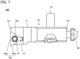
- Fig. 7 is a partial plan view of cutting tool 200.
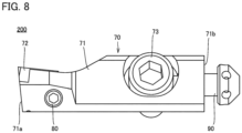
- Fig. 8 is a first partial side view of cutting tool 200.
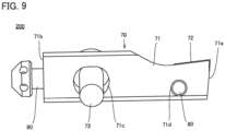
- Fig. 9 is a second partial side view of cutting tool 200.
- body 10 is not illustrated.
- a cartridge 70, a radial-direction adjustment screw 80, and an axial-direction adjustment screw 90 are used instead of blade 20, first attachment screw 30, adjustment piece 40, second attachment screw 50, and adjustment screw 60.
- Cartridge 70 has a cartridge main body 71, a cutting insert 72, an attachment screw 73, and an attachment screw 74.
- Cartridge main body 71 (cartridge 70) extends along the axial direction. Respective ends of cartridge main body 71 in the axial direction are defined as a first end 71a and a second end 71b. First end 71a is an end of cutting tool 200 on the front end side. Second end 71b is an end opposite to first end 71a.
- a through hole 71c and a screw hole 71d are formed in cartridge main body 71.
- Through hole 71c is located close to second end 71b with respect to the center of cartridge main body 71 in the axial direction.
- Screw hole 71d is located close to first end 71a with respect to the center of cartridge main body 71 in the axial direction.
- Cartridge main body 71 is attached to body 10 by inserting attachment screw 73 into through hole 71c and screwing attachment screw 73 into a screw hole (not shown) formed in body 10.
- a through hole 72a is formed in cutting insert 72.
- Cutting insert 72 is attached to cartridge main body 71 by inserting attachment screw 74 into through hole 72a and screwing attachment screw 74 into a screw hole (not shown) formed in cartridge main body 71.
- Cutting insert 72 is attached to an end portion of cartridge main body 71 on the first end 71a side.
- Cutting insert 72 has a cutting edge 72b.
- Cutting edge 72b has a plurality of straight cutting edges 72ba and a plurality of corner cutting edges 72bb.
- Cartridge 70 is attached to body 10 such that the extending direction of one of the plurality of straight cutting edges 72ba is along the radial direction in a state in which cartridge main body 71 is attached to body 10.
- Radial-direction adjustment screw 80 is screwed into screw hole 71d.
- radial-direction adjustment screw 80 When radial-direction adjustment screw 80 is rotated about the central axis, the front end of the stem portion thereof protrudes from cartridge main body 71 and comes into contact with body 10. Thus, the position of the cutting edge of cutting insert 72 in the radial direction is adjusted.
- the stem portion of axial-direction adjustment screw 90 is screwed into a screw hole (not shown) formed in an end surface of cartridge main body 71 on the second end 71b side.
- the head portion of axial-direction adjustment screw 90 is in contact with body 10. Therefore, by rotating axial-direction adjustment screw 90 about the central axis, the position of the cutting edge of cutting insert 72 in the axial direction is adjusted.
- cartridge main body 71 is temporarily fastened to body 10 using attachment screw 73.
- a state in which cartridge main body 71 is temporarily fastened to body 10 by attachment screw 73 is a state in which fastening torque of attachment screw 73 is about 30% of recommended fastening torque.
- the recommended fastening torque is determined by the screw size of attachment screw 73.
- the position of cutting insert 72 in the axial direction is adjusted by advancing or retracting axial-direction adjustment screw 90 along the axial direction.
- the position of cutting insert 72 in the radial direction is adjusted by rotating radial-direction adjustment screw 80 to change an amount of protrusion from cartridge main body 71.
- cartridge main body 71 is fully fastened to body 10 by further rotating attachment screw 73.
- a state in which cartridge main body 71 is fully fastened to body 10 by attachment screw 73 is a state in which fastening torque of attachment screw 73 is more than or equal to the recommended fastening torque.
- the positions of cutting insert 72 (cutting edge 72b) in the radial direction and the axial direction are adjusted.
- the position of cutting insert 72 in the radial direction is adjusted by protruding the front end of the stem portion of radial-direction adjustment screw 80 with respect to cartridge main body 71 and bringing the front end into contact with body 10. Further, the position of radial-direction adjustment screw 80 in the axial direction is greatly separated from the position of attachment screw 73 in the axial direction.
- cartridge main body 71 is deflected with the vicinity of attachment screw 73 serving as a fulcrum. Due to this deflection, the extending direction of cutting edge 72b is inclined with respect to the radial direction. Deflection of cartridge main body 71 occurs also when attachment screw 73 is fully fastened. Accordingly, even though the position of cutting insert 72 in the radial direction is adjusted, the position of cutting insert 72 in the radial direction is displaced when fully fastening attachment screw 73. Thus, in cutting tool 200, precision in position adjustment of cutting insert 72 (cutting edge 72b) becomes low.
- the position of blade 20 in the radial direction is adjusted by advancing or retracting adjustment piece 40, which is located between contact surface 10bb and first blade side surface 22c, along the axial direction.
- the position of adjustment piece 40 in the axial direction is close to the position of first attachment screw 30 in the axial direction.
- blade 20 is less likely to be deflected with first attachment screw 30 serving as a fulcrum, with the result that second cutting edge 21b is less likely to be inclined with respect to the radial direction when adjusting the position of blade 20 in the radial direction and the position of blade 20 in the radial direction is less likely to be displaced when fully fastening first attachment screw 30.
- precision in position adjustment of blade 20 can be improved.
- second cutting edge 21b is further less likely to be inclined with respect to the radial direction when adjusting the position of blade 20 in the radial direction, and displacement of the position in the radial direction is further less likely to occur when fully fastening first attachment screw 30.
- a first test and a second test were performed in order to evaluate precision in position adjustment of cutting edge 21 in cutting tool 100 and precision in position adjustment of cutting edge 72b in cutting tool 200.
- Fig. 10A is a schematic diagram illustrating a method of measuring angle variation amount X1.
- the position of blade 20 is moved outward by 0.05 mm in the radial direction by using second attachment screw 50.
- the shape of cutting edge 21 is measured using venturion 450 (hereinafter, referred to as "cutting edge measurement instrument") provided by Zoller.
- a measurement program used in the cutting edge measurement instrument is Lasso function/No. 21
- a measurement mode of the cutting edge measurement instrument is measurement NN
- measurement precision of the cutting edge measurement instrument is 0.001 mm.
- an angle between second cutting edge 21b and the radial direction is calculated based on the shape of cutting edge 21 obtained as described above. This angle represents angle variation amount X1.
- Fig. 10B is a schematic diagram illustrating a method of measuring angle variation amount X2.
- the position of cutting insert 72 is moved outward by 0.05 mm in the radial direction by using radial-direction adjustment screw 80.
- the shape of cutting edge 72b is measured using a cutting edge measurement instrument. Measurement conditions on this occasion are the same as those described above.
- an angle between straight cutting edge 72ba and the radial direction is calculated based on the shape of cutting edge 72b obtained as described above. This angle represents angle variation amount X2.
- angle variation amount X2 was 0.19°.
- angle variation amount X1 was 0.03°. That is, in cutting tool 100, the variation amount of the cutting edge angle before and after moving it outward in the radial direction was reduced by 84% as compared with cutting tool 200.
- Fig. 11A is a schematic diagram illustrating a method of measuring position variation amount Y1 before and after fully fastening first attachment screw 30.
- Fig. 11A in the measurement of the position variation of blade 20 in the radial direction before and after fully fastening first attachment screw 30, first, the shape of cutting edge 21 before fully fastening first attachment screw 30 (i.e., in a state in which first attachment screw 30 is temporarily fastened) is measured. Second, first attachment screw 30 is fully fastened. Third, the shape of cutting edge 21 after fully fastening first attachment screw 30 is measured.
- position variation amount Y1 is obtained by comparing an outermost position on cutting edge 21 in the radial direction before fully fastening first attachment screw 30 with an outermost position on cutting edge 21 in the radial direction after fully fastening first attachment screw 30. It should be noted that a method of measuring the shape of cutting edge 21 is the same as that in the first test.
- Fig. 11B is a schematic diagram illustrating a method of measuring position variation amount Y2 before and after fully fastening attachment screw 73.
- Fig. 11B in the measurement of the position variation of cutting insert 72 in the radial direction before and after fully fastening attachment screw 73, first, the shape of cutting edge 72b before fully fastening attachment screw 73 (i.e., in a state in which attachment screw 73 is temporarily fastened) is measured. Second, attachment screw 73 is fully fastened. Third, the shape of cutting edge 72b after fully fastening attachment screw 73 is measured.
- position variation amount Y2 is obtained by comparing an outermost position on cutting edge 72b in the radial direction before fully fastening attachment screw 73 with an outermost position on cutting edge 72b in the radial direction after fully fastening attachment screw 73. It should be noted that a method of measuring the shape of cutting edge 72b is the same as that in the first test.
- position variation amount Y2 was 0.009 mm.
- position variation amount Y1 was 0.001 mm. That is, in cutting tool 100, the position variation of the cutting edge in the radial direction before and after fully fastening the attachment screw was reduced by 89% as compared with cutting tool 200.
Landscapes
- Engineering & Computer Science (AREA)
- Mechanical Engineering (AREA)
- Milling Processes (AREA)
- Drilling And Boring (AREA)
- Cutting Tools, Boring Holders, And Turrets (AREA)
Applications Claiming Priority (1)
| Application Number | Priority Date | Filing Date | Title |
|---|---|---|---|
| PCT/JP2022/002921 WO2023144937A1 (ja) | 2022-01-26 | 2022-01-26 | 切削工具 |
Publications (2)
| Publication Number | Publication Date |
|---|---|
| EP4470697A1 true EP4470697A1 (de) | 2024-12-04 |
| EP4470697A4 EP4470697A4 (de) | 2025-03-26 |
Family
ID=84534609
Family Applications (1)
| Application Number | Title | Priority Date | Filing Date |
|---|---|---|---|
| EP22923804.3A Pending EP4470697A4 (de) | 2022-01-26 | 2022-01-26 | Schneidwerkzeug |
Country Status (5)
| Country | Link |
|---|---|
| US (1) | US12397356B2 (de) |
| EP (1) | EP4470697A4 (de) |
| JP (1) | JP7192186B1 (de) |
| CN (1) | CN117980101A (de) |
| WO (1) | WO2023144937A1 (de) |
Families Citing this family (2)
| Publication number | Priority date | Publication date | Assignee | Title |
|---|---|---|---|---|
| USD1085188S1 (en) * | 2023-09-20 | 2025-07-22 | Engis Corporation | Face mill |
| US20250276390A1 (en) * | 2024-02-29 | 2025-09-04 | Iscar, Ltd. | Milling cutter body with insert wedges threadingly engaged to fasteners having transversely directed key recesses |
Family Cites Families (50)
| Publication number | Priority date | Publication date | Assignee | Title |
|---|---|---|---|---|
| US3363299A (en) * | 1966-05-12 | 1968-01-16 | Gen Electric | Cutting tool assembly |
| US3535759A (en) * | 1968-04-12 | 1970-10-27 | Willey S Carbide Tool Co | Milling cutter with adjustable cutting insert bits |
| GB1392445A (en) * | 1971-06-03 | 1975-04-30 | Lloyd Ltd Richard | Milling cutter |
| DE2140004A1 (de) * | 1971-08-10 | 1973-02-22 | Walter Kieninger | Senk- und fraeswerkzeug |
| US3792517A (en) * | 1971-08-17 | 1974-02-19 | Mc Crosky Tool Corp | Rotary machine cutting tools |
| US3708843A (en) * | 1971-11-05 | 1973-01-09 | Ingersoll Milling Machine Co | Holder for indexable cutting insert |
| DE2806079C2 (de) | 1978-02-14 | 1979-10-31 | Guenther 8500 Nuernberg Hertel | Fräswerkzeug mit einstellbar angeordneten Schneideinsätzen |
| US4329091A (en) * | 1980-05-07 | 1982-05-11 | General Electric Company | Floating wedge for use in conjunction with an indexable cutting tool |
| DE3140905C2 (de) * | 1981-06-26 | 1985-10-17 | Sitzmann & Heinlein Gmbh, 8502 Zirndorf | Planfräsmesserkopf |
| DE3201508C1 (de) * | 1982-01-20 | 1988-07-07 | Mapal Fabrik für Präzisionswerkzeuge Dr.Kress KG, 7080 Aalen | Einmesser-Reibahle |
| DE3236921C1 (de) * | 1982-10-06 | 1983-11-17 | Fried. Krupp Gmbh, 4300 Essen | Fräsmesserkopf |
| DE3317916A1 (de) * | 1983-05-17 | 1984-11-22 | Walter Kieninger KG Hartmetallwerkzeugfabrik, 7630 Lahr | Fraeswerkzeug |
| DE3441821A1 (de) * | 1984-11-15 | 1986-05-15 | Walter Kieninger KG Hartmetallwerkzeugfabrik, 7630 Lahr | Messerkopf |
| US4592680A (en) * | 1985-01-24 | 1986-06-03 | Lindsay Harold W | Retention system for rotary cutter having replaceable cutting inserts |
| JPH0511926Y2 (de) | 1987-08-04 | 1993-03-25 | ||
| DE3922963C2 (de) * | 1989-07-12 | 1994-06-01 | Widia Heinlein Gmbh | Drehräumwerkzeug |
| DE8909060U1 (de) * | 1989-07-26 | 1989-09-07 | Hermann Bilz Gmbh & Co, 7300 Esslingen | Zerspanungswerkzeug |
| DE19544556A1 (de) * | 1995-11-29 | 1997-06-05 | Beck August Gmbh Co | Rotierendes Schaftwerkzeug |
| CZ292798A3 (cs) * | 1996-03-19 | 1999-04-14 | Iscar Ltd. | Sestava řezného nástroje |
| US5735649A (en) * | 1996-10-08 | 1998-04-07 | Kaiser Precision Tooling, Inc. | Machine tool cutter position adjustment device |
| DE19800440A1 (de) * | 1998-01-08 | 1999-07-15 | Maier Kg Andreas | Messerkopf mit ein- bis dreidimensional verstellbarem Schneideinsatz und mit formschlüssig aufgenommenem Schneideinsatz |
| US6056484A (en) * | 1998-08-07 | 2000-05-02 | Kennametal Inc. | Device and method for adjusting the position of cutting inserts mounted in a cutting tool |
| US6497537B1 (en) * | 1999-12-17 | 2002-12-24 | Kennametal Pc Inc. | Slotting cutter with cartridge assembly |
| DE10012818B4 (de) * | 2000-03-16 | 2006-04-06 | Wilhelm Fette Gmbh | Plan- oder Eckfräser |
| US6511264B2 (en) * | 2001-02-01 | 2003-01-28 | Ingersoll Cutting Tool Company | Adjustable insert seat |
| US7114890B2 (en) * | 2001-02-13 | 2006-10-03 | Valenite Inc. | Cutting tool adjustment device |
| US6640853B1 (en) * | 2002-09-19 | 2003-11-04 | Hui-Ming Sun | Wood-milling cutter |
| DE10250018A1 (de) * | 2002-10-25 | 2004-05-06 | Komet Präzisionswerkzeuge Robert Breuning Gmbh | Maschinenwerkzeug mit verstellbarer Schneide |
| DE102004058962B4 (de) | 2004-12-08 | 2010-04-01 | MAPAL Fabrik für Präzisionswerkzeuge Dr. Kress KG | Werkzeug |
| JP4393448B2 (ja) * | 2005-11-21 | 2010-01-06 | 株式会社エナテック | 切削装置 |
| DE102006024880A1 (de) * | 2006-05-24 | 2007-11-29 | Kennametal Widia Produktions Gmbh & Co. Kg | Werkzeug mit Einstellvorrichtung |
| JP2009125828A (ja) | 2007-11-20 | 2009-06-11 | Akio Takewa | 外径微調整式ボーリングバー |
| DE102008045674A1 (de) * | 2008-09-04 | 2010-03-11 | Komet Group Gmbh | Maschinenwerkzeug mit verstellbarer Schneidplatte |
| US9597738B2 (en) * | 2011-03-22 | 2017-03-21 | Renault S.A.S. | Milling/surfacing method and device |
| JP5780179B2 (ja) | 2012-02-29 | 2015-09-16 | 三菱マテリアル株式会社 | 穴加工工具 |
| DE102012102747A1 (de) * | 2012-03-29 | 2013-10-02 | Walter Ag | Kurbelwellenfräser |
| US10442016B2 (en) * | 2014-12-17 | 2019-10-15 | Kyocera Corporation | Cutting insert, cutting tool, and method of manufacturing machined product |
| CN107206515A (zh) * | 2015-01-29 | 2017-09-26 | 京瓷株式会社 | 切削工具以及切削加工物的制造方法 |
| US10384275B2 (en) * | 2015-04-21 | 2019-08-20 | Kyocera Corporation | Cutting tool and method for manufacturing the machined product |
| CN107735203B (zh) * | 2015-06-25 | 2019-08-06 | 京瓷株式会社 | 切削工具以及切削加工物的制造方法 |
| WO2016208771A1 (ja) * | 2015-06-26 | 2016-12-29 | 京セラ株式会社 | 切削工具及び切削加工物の製造方法 |
| JP6817717B2 (ja) * | 2016-04-07 | 2021-01-20 | 三菱マテリアル株式会社 | フライスカッタ、切削インサート及びフライス加工方法 |
| DE102016111805A1 (de) * | 2016-06-28 | 2017-12-28 | Komet Group Gmbh | Spanabhebendes Maschinenwerkzeug, insbesondere Maschinenreibwerkzeug |
| US10201861B2 (en) | 2017-02-21 | 2019-02-12 | Iscar, Ltd. | Hole machining tool and guide pad adjustment mechanism therefor |
| DE112017006379T5 (de) * | 2017-07-12 | 2019-08-29 | Beijing Worldia Diamond Tools Co., Ltd. | Wendeplanfräsklinge und Planfräsmesserkopf unter Verwendung dieser Klinge |
| EP3593929B1 (de) * | 2018-05-15 | 2023-03-01 | Sumitomo Electric Hardmetal Corp. | Schneideeinsatz und fräswerkzeug |
| JP6768111B1 (ja) | 2019-04-26 | 2020-10-14 | 株式会社牧野フライス製作所 | 回転工具 |
| JP6765477B1 (ja) | 2019-06-07 | 2020-10-07 | 株式会社牧野フライス製作所 | フライスカッター |
| JP7205707B1 (ja) * | 2022-06-03 | 2023-01-17 | 株式会社タンガロイ | 切削インサート、及び切削インサートを備える切削工具 |
| US11890688B1 (en) * | 2022-08-04 | 2024-02-06 | Iscar, Ltd. | Rotary cutting tool having an integrally formed axial adjustment tongue |
-
2022
- 2022-01-26 US US17/913,859 patent/US12397356B2/en active Active
- 2022-01-26 WO PCT/JP2022/002921 patent/WO2023144937A1/ja not_active Ceased
- 2022-01-26 CN CN202280062542.4A patent/CN117980101A/zh active Pending
- 2022-01-26 EP EP22923804.3A patent/EP4470697A4/de active Pending
- 2022-01-26 JP JP2022538304A patent/JP7192186B1/ja active Active
Also Published As
| Publication number | Publication date |
|---|---|
| EP4470697A4 (de) | 2025-03-26 |
| US12397356B2 (en) | 2025-08-26 |
| WO2023144937A1 (ja) | 2023-08-03 |
| CN117980101A (zh) | 2024-05-03 |
| JP7192186B1 (ja) | 2022-12-20 |
| US20240207946A1 (en) | 2024-06-27 |
| JPWO2023144937A1 (de) | 2023-08-03 |
Similar Documents
| Publication | Publication Date | Title |
|---|---|---|
| EP4470697A1 (de) | Schneidwerkzeug | |
| CN100528434C (zh) | 钻头和具有导引构件的钻尖 | |
| EP2764940B1 (de) | Schneideinsatz und schneidwerkzeug mit austauschbarer klinge | |
| EP2883640B1 (de) | Schneidwerkzeug mit Anschlägen und Werkzeughalter und Schneideinsatz dafür | |
| US9656327B2 (en) | Drill head for deep hole cutting | |
| US20120315101A1 (en) | Throw-away rotating tool | |
| EP2006042B1 (de) | Wegwerfbohrer, einsatz für wegwerfbohrer und den wegwerfbohrer verwendendes schneidverfahren | |
| US9352405B2 (en) | Metal-cutting tool, in particular reaming tool | |
| US20140212235A1 (en) | Drill cutting insert | |
| EP3552742B1 (de) | Wendeschneidplatte und rotierendes schneidwerkzeug mit indexierbaren schneidkanten | |
| US10022810B2 (en) | Cutting tool and method for manufacturing machined product | |
| US12151293B2 (en) | Combination tool as well as drills for such a drilling/chamfering tool | |
| JP5564958B2 (ja) | 刃先交換式溝入れ工具及び端面溝入れ加工方法 | |
| EP4275819A1 (de) | Schneideinsatz, halter und schneidwerkzeug mit auswechselbarer klingenspitze | |
| EP3401047A1 (de) | Schneidwerkzeug | |
| JP4765807B2 (ja) | 穴加工工具及びインサート | |
| JP2655995B2 (ja) | 二枚刃切削工具 | |
| JP4971649B2 (ja) | 切削工具 | |
| JP4946229B2 (ja) | 穴加工工具 | |
| JP4967863B2 (ja) | 穴加工工具 | |
| JP2007130739A (ja) | 穴加工工具 | |
| JP4770254B2 (ja) | 切削工具 | |
| JP4876748B2 (ja) | 穴加工工具 | |
| EP3943227A1 (de) | Wechselbohrer, schneideinsatz und bohrerhauptkörper | |
| JP4816041B2 (ja) | インサート式ドリル及びインサート |
Legal Events
| Date | Code | Title | Description |
|---|---|---|---|
| STAA | Information on the status of an ep patent application or granted ep patent |
Free format text: STATUS: THE INTERNATIONAL PUBLICATION HAS BEEN MADE |
|
| PUAI | Public reference made under article 153(3) epc to a published international application that has entered the european phase |
Free format text: ORIGINAL CODE: 0009012 |
|
| STAA | Information on the status of an ep patent application or granted ep patent |
Free format text: STATUS: REQUEST FOR EXAMINATION WAS MADE |
|
| 17P | Request for examination filed |
Effective date: 20240423 |
|
| AK | Designated contracting states |
Kind code of ref document: A1 Designated state(s): AL AT BE BG CH CY CZ DE DK EE ES FI FR GB GR HR HU IE IS IT LI LT LU LV MC MK MT NL NO PL PT RO RS SE SI SK SM TR |
|
| A4 | Supplementary search report drawn up and despatched |
Effective date: 20250220 |
|
| RIC1 | Information provided on ipc code assigned before grant |
Ipc: B23B 27/16 20060101ALN20250214BHEP Ipc: B23C 5/22 20060101ALI20250214BHEP Ipc: B23C 5/06 20060101ALI20250214BHEP Ipc: B23C 5/24 20060101AFI20250214BHEP |
|
| DAV | Request for validation of the european patent (deleted) | ||
| DAX | Request for extension of the european patent (deleted) |