EP4458501A1 - Drahterosionsmaschine - Google Patents
Drahterosionsmaschine Download PDFInfo
- Publication number
- EP4458501A1 EP4458501A1 EP21969984.0A EP21969984A EP4458501A1 EP 4458501 A1 EP4458501 A1 EP 4458501A1 EP 21969984 A EP21969984 A EP 21969984A EP 4458501 A1 EP4458501 A1 EP 4458501A1
- Authority
- EP
- European Patent Office
- Prior art keywords
- wire
- electrode
- wire electrode
- discharge machine
- cutting
- Prior art date
- Legal status (The legal status is an assumption and is not a legal conclusion. Google has not performed a legal analysis and makes no representation as to the accuracy of the status listed.)
- Pending
Links
Images
Classifications
-
- B—PERFORMING OPERATIONS; TRANSPORTING
- B23—MACHINE TOOLS; METAL-WORKING NOT OTHERWISE PROVIDED FOR
- B23H—WORKING OF METAL BY THE ACTION OF A HIGH CONCENTRATION OF ELECTRIC CURRENT ON A WORKPIECE USING AN ELECTRODE WHICH TAKES THE PLACE OF A TOOL; SUCH WORKING COMBINED WITH OTHER FORMS OF WORKING OF METAL
- B23H7/00—Processes or apparatus applicable to both electrical discharge machining and electrochemical machining
- B23H7/02—Wire-cutting
- B23H7/08—Wire electrodes
- B23H7/10—Supporting, winding or electrical connection of wire-electrode
Definitions
- the present invention relates to a wire electrical discharge machine (wire electric discharge machine).
- JP H06-304819 A discloses a wire electric discharge machine in which a wire electrode is cut by Joule heat between first and second wire cutting electrodes.
- a wire feed pipe structure is provided between the first and second wire cutting electrodes.
- the interior of the wire feed pipe structure is constantly cooled by cooling water. Since the annealing effect on the wire electrode is produced inside the wire feed pipe structure, the tendency of the wire electrode to coil or curl is suppressed.
- the wire electrical discharge machine disclosed in JP H06-304819 A has a problem that the straightness of the wire electrode after cutting is poor in the case of a relatively thin wire electrode.
- the present invention has the object of solving the aforementioned problem.
- a wire electrical discharge machine for machining a workpiece by generating electric discharge by a wire electrode
- the wire electrical discharge machine including: an upper wire guide configured to support the wire electrode above the workpiece; a roller configured to feed the wire electrode from above the upper wire guide to the upper wire guide; a pipe through which the wire electrode fed from the roller is inserted and through which a cooling medium flows; a positive electrode and a negative electrode configured to be in contact with the wire electrode between the pipe and the upper wire guide in a state of being spaced apart from each other in a feeding direction of the wire electrode; and a power supply configured to apply a cutting voltage between the positive electrode and the negative electrode when the wire electrode is cut.
- the straightness of a relatively thin wire electrode after cutting is maintained suitably.
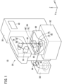
- FIG. 1 is a diagram showing a configuration of a wire electrical discharge machine 10 according to an embodiment.
- the X direction, Y direction, and Z direction shown in FIG. 1 are orthogonal to each other, and gravity acts in the -Z direction.
- the wire electrical discharge machine 10 includes a main body 20, a machining power supply 30, and a control device 40.
- the machining power supply 30 applies a voltage to an inter-electrode gap formed between a wire electrode 60 and a workpiece (not shown) to generate electric discharge.
- the workpiece is supported on a table 62.
- the wire electrical discharge machine 10 performs electrical discharge machining on the workpiece by generating electric discharge at the inter-electrode gap by the wire electrode 60.
- the wire electrical discharge machine 10 causes the wire electrode 60 to move relatively to the workpiece along a machining path specified by a predetermined program, during an electrical discharge machining.
- the relative movement between the wire electrode 60 and the workpiece is performed by moving the table 62, for example.
- the wire electrical discharge machine 10 includes an upper wire guide 64 and a lower wire guide 66.
- the upper wire guide 64 includes an upper guide block 68, an upper die guide 70, and an upper nozzle (not shown).
- the lower wire guide 66 includes a lower guide block 72, a lower die guide 74, and a lower nozzle (not shown).
- the upper wire guide 64 supports the wire electrode 60 above the table 62 and the workpiece (on the +Z direction side).
- the lower wire guide 66 supports the wire electrode 60 below the table 62 (on the -Z direction side).
- the wire electrode 60 is supplied from a wire bobbin 76 in a feeding direction at a predetermined feedrate.
- the wire electrode 60 is fed via a roller 78, the upper wire guide 64, and the lower wire guide 66.
- the roller 78 includes a guide roller (not shown), a brake roller 80, and a first pinch roller 82.
- the roller 78 feeds the wire electrode 60 from above the upper wire guide 64 to the upper wire guide 64.
- the wire electrode 60 is sandwiched and held between a second pinch roller 84 and a feed roller 86.
- the wire electrode 60 is collected in a collection box 88.
- a work pan 90 may store a dielectric working fluid.
- the table 62, the workpiece, the upper wire guide 64, and the lower wire guide 66 are immersed in the dielectric working fluid.
- the work pan 90 is disposed on a bed 92.
- the control device 40 controls the main body 20 to perform the above-described electrical discharge machining.
- the control device 40 controls the main body 20 to cut and feed the wire electrode 60.
- the wire electrode 60 is also cut and fed. Further, also when the wire electrode 60 is broken during electrical discharge machining, the wire electrode 60 is newly cut at a position above the broken position and fed.
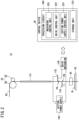
- FIG. 2 is a diagram illustrating how a cutting voltage is applied to the wire electrode 60.
- FIG. 2 shows a workpiece W mounted on the table 62.
- the upper wire guide 64 supports the wire electrode 60 above the workpiece W.
- the wire electrode 60 fed from the roller 78 to the upper wire guide 64 is inserted through a pipe 110.
- a cooling medium flows through the pipe 110.
- the roller 78 rotates in a direction opposite to the direction in which the roller 78 rotates when the wire electrode 60 is fed, and pulls up the wire electrode 60, thereby applying tension to the wire electrode 60.
- a positive electrode 132 and a negative electrode 134 are driven by a drive mechanism 136 and come into contact with the wire electrode 60 below the pipe 110.
- the positive electrode 132 and the negative electrode 134 are in contact with the wire electrode 60 while being spaced apart from each other in the feeding direction of the wire electrode 60.
- the positive electrode 132 and the negative electrode 134 are in contact with the wire electrode 60 between the pipe 110 and the upper wire guide 64.
- the wire electrode 60 and the positive electrode 132 are in contact with each other at a contact position PA.
- the wire electrode 60 and the negative electrode 134 are in contact with each other at a contact position PB.
- the positive terminal of a cutting power supply 140 is connected to the positive electrode 132.
- the negative terminal of the cutting power supply 140 is connected to the negative electrode 134.
- the cutting power supply 140 applies a cutting voltage between the positive electrode 132 and the negative electrode 134.
- the wire electrode 60 is cut by Joule heat generated between the contact position PA of the positive electrode 132 and the contact position PB of the negative electrode 134.
- the control device 40 includes a processing circuit 200 and a storage unit 210.
- the processing circuit 200 includes a processor such as a CPU.
- the storage unit 210 includes a volatile memory such as a RAM and a non-volatile memory such as a ROM and a flash memory.
- the storage unit 210 stores programs and the like.
- the processing circuit 200 executes the program to realize a machining control unit 220, a drive control unit 222, and a cutting power supply control unit 224. At least part of the machining control unit 220, the drive control unit 222, and the cutting power supply control unit 224 may be implemented by an ASIC, an FPGA, or another integrated circuit.
- the machining control unit 220 controls a motor (not shown) to feed the wire electrode 60 from the upper wire guide 64 toward the lower wire guide 66.
- the machining control unit 220 controls a motor (not shown) to move the wire electrode 60 relative to the workpiece W.
- the machining control unit 220 controls the machining power supply 30 to generate electric discharge at the inter-electrode gap.
- the drive control unit 222 controls the drive mechanism 136 to bring the positive electrode 132 and the negative electrode 134 into contact with the wire electrode 60.
- the cutting power supply control unit 224 controls the cutting power supply 140 to apply a cutting voltage between the positive electrode 132 and the negative electrode 134. Joule heat is generated between the contact position PA and the contact position PB.
- JP H06-304819 A when the conventional technique disclosed in JP H06-304819 A is used, Joule heat is generated even in a section where the wire electrode is inserted in the pipe 110.
- the cooling medium flows through the pipe 110 along the wire electrode 60. Therefore, the wire electrode 60 is cooled in the section where the wire electrode is inserted in the pipe 110. Therefore, in this section, an annealing effect is obtained, and it is expected to improve the straightness of the wire electrode 60 after cutting.
- the annealing effect is smaller than in the case of standard diameters exceeding 0.1 mm and accordingly the straightness of the wire electrode 60 after cutting is inferior to that case.
- Joule heat is not generated in the section where the wire electrode 60 is inserted in the pipe 110, and thus the straightness of the wire electrode 60 in this section is maintained after cutting.
- a portion of the wire electrode 60 where Joule heat is generated is limited to the section between the contact position PA and the contact position PB.
- the length of the portion of the wire electrode 60 inserted in the pipe 110 is several tens of centimeters, whereas the length of the section between the contact position PA and the contact position PB is several centimeters. Therefore, the section in which the straightness of the cut wire electrode 60 is impaired is limited to a relatively short section, i.e., the section between the contact position PA and the contact position PB.
- the cutting power supply 140 applies the cutting voltage between the positive electrode 132 and the negative electrode 134.
- the cut voltage may be applied to the section where the wire electrode 60 is inserted in the pipe 110.
- the wire electrode 60 is subjected to an annealing effect due to cooling, so that the straightness of the wire electrode 60 is improved.
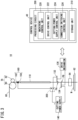
- FIG. 3 is a diagram illustrating how a cutting voltage is applied to the wire electrode 60 in a modification. Description of members shown in FIG. 3 that are denoted by the same reference numerals as those of the members shown in FIG. 2 will be omitted.
- a chuck 160 is disposed between the roller 78 and the pipe 110. The chuck 160 has a pair of clamp electrodes 162 and 164.
- the chuck 160 clamps the wire electrode 60 by the pair of clamp electrodes 162 and 164, thereby holding the wire electrode 60.
- the cutting power supply 140 applies a cutting voltage between at least one of the pair of clamp electrodes 162, 164 and the negative electrode 134.
- the wire electrode 60 is cut by Joule heat generated between the pipe 110, which is not cooled, and the negative electrode 134.
- the wire electrode 60 having a relatively small diameter is cut, the wire electrode 60 is not clamped by the pair of clamp electrodes 162 and 164.
- the cutting power supply 140 applies the cutting voltage between the positive electrode 132 and the negative electrode 134.
- FIG. 3 shows a connection switching control unit 226 and a switch 300.
- the connection switching control unit 226 is realized by the processing circuit 200 of the control device 40 executing a program.
- the connection switching control unit 226 may be realized by an ASIC, an FPGA, or another integrated circuit.
- the switch 300 switches the connection destination of the positive terminal of the cutting power supply 140 between the positive electrode 132 and the clamp electrode 162.
- the switch 300 may connect the positive terminal of the cutting power supply 140 to the clamp electrode 164 instead of the clamp electrode 162 or in addition to the clamp electrode 162.
- the connection switching control unit 226 of the control device 40 controls the switch 300 to select the connection destination of the positive electrode of the cutting power supply 140, in accordance with the wire diameter information.
- the connection switching control unit 226 controls the switch 300 to connect the positive electrode of the cutting power supply 140 to the positive electrode 132.
- the connection switching control unit 226 controls the switch 300 to connect the positive electrode of the cutting power supply 140 to the clamp electrode 162.
- the connection switching control unit 226 of the control device 40 may control the switch 300 to select the connection destination of the positive electrode of the cutting power supply 140, in accordance with material information about the material of the wire electrode 60.
- the connection switching control unit 226 controls the switch 300 to connect the positive terminal of the cutting power supply 140 to the positive electrode 132.
- the connection switching control unit 226 controls the switch 300 to connect the positive terminal of the cutting power supply 140 to the clamp electrode 162.
- the material information is input to the control device 40 by the user.
Landscapes
- Chemical & Material Sciences (AREA)
- Chemical Kinetics & Catalysis (AREA)
- Electrochemistry (AREA)
- Engineering & Computer Science (AREA)
- Mechanical Engineering (AREA)
- Electrical Discharge Machining, Electrochemical Machining, And Combined Machining (AREA)
Applications Claiming Priority (1)
| Application Number | Priority Date | Filing Date | Title |
|---|---|---|---|
| PCT/JP2021/048808 WO2023127103A1 (ja) | 2021-12-28 | 2021-12-28 | ワイヤ放電加工機 |
Publications (2)
| Publication Number | Publication Date |
|---|---|
| EP4458501A1 true EP4458501A1 (de) | 2024-11-06 |
| EP4458501A4 EP4458501A4 (de) | 2026-04-29 |
Family
ID=86998464
Family Applications (1)
| Application Number | Title | Priority Date | Filing Date |
|---|---|---|---|
| EP21969984.0A Pending EP4458501A4 (de) | 2021-12-28 | 2021-12-28 | Drahterosionsmaschine |
Country Status (5)
| Country | Link |
|---|---|
| EP (1) | EP4458501A4 (de) |
| JP (1) | JP7772833B2 (de) |
| CN (1) | CN118434525A (de) |
| TW (1) | TW202325445A (de) |
| WO (1) | WO2023127103A1 (de) |
Family Cites Families (4)
| Publication number | Priority date | Publication date | Assignee | Title |
|---|---|---|---|---|
| JP3371014B2 (ja) | 1993-04-21 | 2003-01-27 | ファナック株式会社 | ワイヤ放電加工機 |
| JP2000126935A (ja) * | 1998-10-27 | 2000-05-09 | Okuma Corp | ワイヤ電極の切断方法及び装置 |
| JP2003285227A (ja) * | 2002-03-28 | 2003-10-07 | Brother Ind Ltd | ワイヤ放電加工機及びその制御方法 |
| JP5155424B2 (ja) * | 2011-05-30 | 2013-03-06 | ファナック株式会社 | ワイヤ電極切断機能を備えたワイヤカット放電加工機 |
-
2021
- 2021-12-28 EP EP21969984.0A patent/EP4458501A4/de active Pending
- 2021-12-28 WO PCT/JP2021/048808 patent/WO2023127103A1/ja not_active Ceased
- 2021-12-28 JP JP2023570584A patent/JP7772833B2/ja active Active
- 2021-12-28 CN CN202180105199.2A patent/CN118434525A/zh active Pending
-
2022
- 2022-12-22 TW TW111149381A patent/TW202325445A/zh unknown
Also Published As
| Publication number | Publication date |
|---|---|
| EP4458501A4 (de) | 2026-04-29 |
| CN118434525A (zh) | 2024-08-02 |
| WO2023127103A1 (ja) | 2023-07-06 |
| JP7772833B2 (ja) | 2025-11-18 |
| JPWO2023127103A1 (de) | 2023-07-06 |
| TW202325445A (zh) | 2023-07-01 |
Similar Documents
| Publication | Publication Date | Title |
|---|---|---|
| CN113677470B (zh) | 线放电加工机 | |
| WO2006041213A1 (ja) | 自動ワイヤ挿通装置 | |
| JP2017087395A (ja) | マルチワイヤ放電加工装置 | |
| JP3815329B2 (ja) | 細穴加工用放電加工装置 | |
| CN109396581B (zh) | 一种导体材料的切割装置及其工作方法 | |
| EP4458501A1 (de) | Drahterosionsmaschine | |
| JPWO2001089752A1 (ja) | 細穴加工用放電加工装置 | |
| JP2015037813A (ja) | 加工用電源を切り替えてワイヤ切断用に使用するワイヤ放電加工機 | |
| JPH06143043A (ja) | 微細穴放電加工方法および装置 | |
| US20110114603A1 (en) | Wire cut electrical discharge machine | |
| JPS63123632A (ja) | ワイヤ放電加工装置 | |
| KR200436567Y1 (ko) | 와이어 방전 가공용 지그 | |
| JP2015009346A (ja) | 電解ドレッシング方法、及び電解ドレッシング装置 | |
| JP3541340B2 (ja) | ワイヤカット放電加工方法 | |
| JPH10315053A (ja) | ワイヤ放電加工装置 | |
| JPS63306829A (ja) | ワイヤカット放電加工装置 | |
| JP2020185621A (ja) | ワイヤ放電加工機およびワイヤ放電加工方法 | |
| JPS61164725A (ja) | ワイヤ電極案内 | |
| JPS61293727A (ja) | ワイヤ切断装置 | |
| JPH07106499B2 (ja) | 微細孔の精密仕上げ装置 | |
| JPH0545368B2 (de) | ||
| JP2017119332A (ja) | 放電加工方法 | |
| JPS61164726A (ja) | ワイヤ電極案内 | |
| JPS6339738A (ja) | 穿孔加工装置 | |
| JP2016140925A (ja) | マルチワイヤ放電加工装置 |
Legal Events
| Date | Code | Title | Description |
|---|---|---|---|
| STAA | Information on the status of an ep patent application or granted ep patent |
Free format text: STATUS: THE INTERNATIONAL PUBLICATION HAS BEEN MADE |
|
| PUAI | Public reference made under article 153(3) epc to a published international application that has entered the european phase |
Free format text: ORIGINAL CODE: 0009012 |
|
| STAA | Information on the status of an ep patent application or granted ep patent |
Free format text: STATUS: REQUEST FOR EXAMINATION WAS MADE |
|
| 17P | Request for examination filed |
Effective date: 20240620 |
|
| AK | Designated contracting states |
Kind code of ref document: A1 Designated state(s): AL AT BE BG CH CY CZ DE DK EE ES FI FR GB GR HR HU IE IS IT LI LT LU LV MC MK MT NL NO PL PT RO RS SE SI SK SM TR |
|
| DAV | Request for validation of the european patent (deleted) | ||
| DAX | Request for extension of the european patent (deleted) | ||
| A4 | Supplementary search report drawn up and despatched |
Effective date: 20260330 |
|
| RIC1 | Information provided on ipc code assigned before grant |
Ipc: B23H 7/10 20060101AFI20260324BHEP |