EP4454512A2 - Systeme, vorrichtungen und techniken zur automatisierten schuhschnürung - Google Patents
Systeme, vorrichtungen und techniken zur automatisierten schuhschnürung Download PDFInfo
- Publication number
- EP4454512A2 EP4454512A2 EP24200161.8A EP24200161A EP4454512A2 EP 4454512 A2 EP4454512 A2 EP 4454512A2 EP 24200161 A EP24200161 A EP 24200161A EP 4454512 A2 EP4454512 A2 EP 4454512A2
- Authority
- EP
- European Patent Office
- Prior art keywords
- lace
- spool
- lacing engine
- cable
- lace cable
- Prior art date
- Legal status (The legal status is an assumption and is not a legal conclusion. Google has not performed a legal analysis and makes no representation as to the accuracy of the status listed.)
- Pending
Links
Images

Classifications
-
- A—HUMAN NECESSITIES
- A43—FOOTWEAR
- A43B—CHARACTERISTIC FEATURES OF FOOTWEAR; PARTS OF FOOTWEAR
- A43B13/00—Soles; Sole-and-heel integral units
- A43B13/14—Soles; Sole-and-heel integral units characterised by the constructive form
-
- A—HUMAN NECESSITIES
- A43—FOOTWEAR
- A43B—CHARACTERISTIC FEATURES OF FOOTWEAR; PARTS OF FOOTWEAR
- A43B3/00—Footwear characterised by the shape or the use
- A43B3/34—Footwear characterised by the shape or the use with electrical or electronic arrangements
-
- A—HUMAN NECESSITIES
- A43—FOOTWEAR
- A43B—CHARACTERISTIC FEATURES OF FOOTWEAR; PARTS OF FOOTWEAR
- A43B3/00—Footwear characterised by the shape or the use
- A43B3/34—Footwear characterised by the shape or the use with electrical or electronic arrangements
- A43B3/38—Footwear characterised by the shape or the use with electrical or electronic arrangements with power sources
-
- A—HUMAN NECESSITIES
- A43—FOOTWEAR
- A43B—CHARACTERISTIC FEATURES OF FOOTWEAR; PARTS OF FOOTWEAR
- A43B5/00—Footwear for sporting purposes
-
- A—HUMAN NECESSITIES
- A43—FOOTWEAR
- A43C—FASTENINGS OR ATTACHMENTS OF FOOTWEAR; LACES IN GENERAL
- A43C1/00—Shoe lacing fastenings
-
- A—HUMAN NECESSITIES
- A43—FOOTWEAR
- A43C—FASTENINGS OR ATTACHMENTS OF FOOTWEAR; LACES IN GENERAL
- A43C11/00—Other fastenings specially adapted for shoes
- A43C11/16—Fastenings secured by wire, bolts, or the like
- A43C11/165—Fastenings secured by wire, bolts, or the like characterised by a spool, reel or pulley for winding up cables, laces or straps by rotation
-
- A—HUMAN NECESSITIES
- A43—FOOTWEAR
- A43C—FASTENINGS OR ATTACHMENTS OF FOOTWEAR; LACES IN GENERAL
- A43C7/00—Holding-devices for laces
-
- A—HUMAN NECESSITIES
- A43—FOOTWEAR
- A43C—FASTENINGS OR ATTACHMENTS OF FOOTWEAR; LACES IN GENERAL
- A43C7/00—Holding-devices for laces
- A43C7/08—Clamps drawn tight by laces
-
- B—PERFORMING OPERATIONS; TRANSPORTING
- B65—CONVEYING; PACKING; STORING; HANDLING THIN OR FILAMENTARY MATERIAL
- B65H—HANDLING THIN OR FILAMENTARY MATERIAL, e.g. SHEETS, WEBS, CABLES
- B65H59/00—Adjusting or controlling tension in filamentary material, e.g. for preventing snarling; Applications of tension indicators
-
- B—PERFORMING OPERATIONS; TRANSPORTING
- B65—CONVEYING; PACKING; STORING; HANDLING THIN OR FILAMENTARY MATERIAL
- B65H—HANDLING THIN OR FILAMENTARY MATERIAL, e.g. SHEETS, WEBS, CABLES
- B65H69/00—Methods of, or devices for, interconnecting successive lengths of material; Knot-tying devices ;Control of the correct working of the interconnecting device
-
- B—PERFORMING OPERATIONS; TRANSPORTING
- B65—CONVEYING; PACKING; STORING; HANDLING THIN OR FILAMENTARY MATERIAL
- B65H—HANDLING THIN OR FILAMENTARY MATERIAL, e.g. SHEETS, WEBS, CABLES
- B65H75/00—Storing webs, tapes, or filamentary material, e.g. on reels
- B65H75/02—Cores, formers, supports, or holders for coiled, wound, or folded material, e.g. reels, spindles, bobbins, cop tubes, cans, mandrels or chucks
- B65H75/34—Cores, formers, supports, or holders for coiled, wound, or folded material, e.g. reels, spindles, bobbins, cop tubes, cans, mandrels or chucks specially adapted or mounted for storing and repeatedly paying-out and re-storing lengths of material provided for particular purposes, e.g. anchored hoses, power cables
- B65H75/36—Cores, formers, supports, or holders for coiled, wound, or folded material, e.g. reels, spindles, bobbins, cop tubes, cans, mandrels or chucks specially adapted or mounted for storing and repeatedly paying-out and re-storing lengths of material provided for particular purposes, e.g. anchored hoses, power cables without essentially involving the use of a core or former internal to a stored package of material, e.g. with stored material housed within casing or container, or intermittently engaging a plurality of supports as in sinuous or serpentine fashion
- B65H75/368—Cores, formers, supports, or holders for coiled, wound, or folded material, e.g. reels, spindles, bobbins, cop tubes, cans, mandrels or chucks specially adapted or mounted for storing and repeatedly paying-out and re-storing lengths of material provided for particular purposes, e.g. anchored hoses, power cables without essentially involving the use of a core or former internal to a stored package of material, e.g. with stored material housed within casing or container, or intermittently engaging a plurality of supports as in sinuous or serpentine fashion with pulleys
-
- B—PERFORMING OPERATIONS; TRANSPORTING
- B65—CONVEYING; PACKING; STORING; HANDLING THIN OR FILAMENTARY MATERIAL
- B65H—HANDLING THIN OR FILAMENTARY MATERIAL, e.g. SHEETS, WEBS, CABLES
- B65H75/00—Storing webs, tapes, or filamentary material, e.g. on reels
- B65H75/02—Cores, formers, supports, or holders for coiled, wound, or folded material, e.g. reels, spindles, bobbins, cop tubes, cans, mandrels or chucks
- B65H75/34—Cores, formers, supports, or holders for coiled, wound, or folded material, e.g. reels, spindles, bobbins, cop tubes, cans, mandrels or chucks specially adapted or mounted for storing and repeatedly paying-out and re-storing lengths of material provided for particular purposes, e.g. anchored hoses, power cables
- B65H75/38—Cores, formers, supports, or holders for coiled, wound, or folded material, e.g. reels, spindles, bobbins, cop tubes, cans, mandrels or chucks specially adapted or mounted for storing and repeatedly paying-out and re-storing lengths of material provided for particular purposes, e.g. anchored hoses, power cables involving the use of a core or former internal to, and supporting, a stored package of material
- B65H75/44—Constructional details
- B65H75/4418—Arrangements for stopping winding or unwinding; Arrangements for releasing the stop means
- B65H75/4428—Arrangements for stopping winding or unwinding; Arrangements for releasing the stop means acting on the reel or on a reel blocking mechanism
-
- B—PERFORMING OPERATIONS; TRANSPORTING
- B65—CONVEYING; PACKING; STORING; HANDLING THIN OR FILAMENTARY MATERIAL
- B65H—HANDLING THIN OR FILAMENTARY MATERIAL, e.g. SHEETS, WEBS, CABLES
- B65H75/00—Storing webs, tapes, or filamentary material, e.g. on reels
- B65H75/02—Cores, formers, supports, or holders for coiled, wound, or folded material, e.g. reels, spindles, bobbins, cop tubes, cans, mandrels or chucks
- B65H75/34—Cores, formers, supports, or holders for coiled, wound, or folded material, e.g. reels, spindles, bobbins, cop tubes, cans, mandrels or chucks specially adapted or mounted for storing and repeatedly paying-out and re-storing lengths of material provided for particular purposes, e.g. anchored hoses, power cables
- B65H75/38—Cores, formers, supports, or holders for coiled, wound, or folded material, e.g. reels, spindles, bobbins, cop tubes, cans, mandrels or chucks specially adapted or mounted for storing and repeatedly paying-out and re-storing lengths of material provided for particular purposes, e.g. anchored hoses, power cables involving the use of a core or former internal to, and supporting, a stored package of material
- B65H75/44—Constructional details
- B65H75/4481—Arrangements or adaptations for driving the reel or the material
- B65H75/4484—Electronic arrangements or adaptations for controlling the winding or unwinding process, e.g. with sensors
-
- F—MECHANICAL ENGINEERING; LIGHTING; HEATING; WEAPONS; BLASTING
- F16—ENGINEERING ELEMENTS AND UNITS; GENERAL MEASURES FOR PRODUCING AND MAINTAINING EFFECTIVE FUNCTIONING OF MACHINES OR INSTALLATIONS; THERMAL INSULATION IN GENERAL
- F16G—BELTS, CABLES, OR ROPES, PREDOMINANTLY USED FOR DRIVING PURPOSES; CHAINS; FITTINGS PREDOMINANTLY USED THEREFOR
- F16G11/00—Means for fastening cables or ropes to one another or to other objects; Caps or sleeves for fixing on cables or ropes
-
- F—MECHANICAL ENGINEERING; LIGHTING; HEATING; WEAPONS; BLASTING
- F16—ENGINEERING ELEMENTS AND UNITS; GENERAL MEASURES FOR PRODUCING AND MAINTAINING EFFECTIVE FUNCTIONING OF MACHINES OR INSTALLATIONS; THERMAL INSULATION IN GENERAL
- F16H—GEARING
- F16H1/00—Toothed gearings for conveying rotary motion
- F16H1/28—Toothed gearings for conveying rotary motion with gears having orbital motion
- F16H1/2863—Arrangements for adjusting or for taking-up backlash
-
- B—PERFORMING OPERATIONS; TRANSPORTING
- B65—CONVEYING; PACKING; STORING; HANDLING THIN OR FILAMENTARY MATERIAL
- B65H—HANDLING THIN OR FILAMENTARY MATERIAL, e.g. SHEETS, WEBS, CABLES
- B65H2403/00—Power transmission; Driving means
- B65H2403/40—Toothed gearings
- B65H2403/46—Toothed gearings worm gearing
-
- B—PERFORMING OPERATIONS; TRANSPORTING
- B65—CONVEYING; PACKING; STORING; HANDLING THIN OR FILAMENTARY MATERIAL
- B65H—HANDLING THIN OR FILAMENTARY MATERIAL, e.g. SHEETS, WEBS, CABLES
- B65H2511/00—Dimensions; Position; Numbers; Identification; Occurrences
- B65H2511/40—Identification
- B65H2511/411—Identification of colour
-
- B—PERFORMING OPERATIONS; TRANSPORTING
- B65—CONVEYING; PACKING; STORING; HANDLING THIN OR FILAMENTARY MATERIAL
- B65H—HANDLING THIN OR FILAMENTARY MATERIAL, e.g. SHEETS, WEBS, CABLES
- B65H2515/00—Physical entities not provided for in groups B65H2511/00 or B65H2513/00
- B65H2515/30—Forces; Stresses
- B65H2515/31—Tensile forces
-
- B—PERFORMING OPERATIONS; TRANSPORTING
- B65—CONVEYING; PACKING; STORING; HANDLING THIN OR FILAMENTARY MATERIAL
- B65H—HANDLING THIN OR FILAMENTARY MATERIAL, e.g. SHEETS, WEBS, CABLES
- B65H2553/00—Sensing or detecting means
- B65H2553/20—Sensing or detecting means using electric elements
-
- B—PERFORMING OPERATIONS; TRANSPORTING
- B65—CONVEYING; PACKING; STORING; HANDLING THIN OR FILAMENTARY MATERIAL
- B65H—HANDLING THIN OR FILAMENTARY MATERIAL, e.g. SHEETS, WEBS, CABLES
- B65H2701/00—Handled material; Storage means
- B65H2701/30—Handled filamentary material
- B65H2701/39—Other types of filamentary materials or special applications
-
- F—MECHANICAL ENGINEERING; LIGHTING; HEATING; WEAPONS; BLASTING
- F16—ENGINEERING ELEMENTS AND UNITS; GENERAL MEASURES FOR PRODUCING AND MAINTAINING EFFECTIVE FUNCTIONING OF MACHINES OR INSTALLATIONS; THERMAL INSULATION IN GENERAL
- F16G—BELTS, CABLES, OR ROPES, PREDOMINANTLY USED FOR DRIVING PURPOSES; CHAINS; FITTINGS PREDOMINANTLY USED THEREFOR
- F16G11/00—Means for fastening cables or ropes to one another or to other objects; Caps or sleeves for fixing on cables or ropes
- F16G11/10—Quick-acting fastenings; Clamps holding in one direction only
- F16G11/105—Clamps holding in one direction only
- F16G11/106—Clamps holding in one direction only using a toothed surface
-
- F—MECHANICAL ENGINEERING; LIGHTING; HEATING; WEAPONS; BLASTING
- F16—ENGINEERING ELEMENTS AND UNITS; GENERAL MEASURES FOR PRODUCING AND MAINTAINING EFFECTIVE FUNCTIONING OF MACHINES OR INSTALLATIONS; THERMAL INSULATION IN GENERAL
- F16G—BELTS, CABLES, OR ROPES, PREDOMINANTLY USED FOR DRIVING PURPOSES; CHAINS; FITTINGS PREDOMINANTLY USED THEREFOR
- F16G11/00—Means for fastening cables or ropes to one another or to other objects; Caps or sleeves for fixing on cables or ropes
- F16G11/12—Connections or attachments, e.g. turnbuckles, adapted for straining of cables, ropes, or wire
-
- F—MECHANICAL ENGINEERING; LIGHTING; HEATING; WEAPONS; BLASTING
- F16—ENGINEERING ELEMENTS AND UNITS; GENERAL MEASURES FOR PRODUCING AND MAINTAINING EFFECTIVE FUNCTIONING OF MACHINES OR INSTALLATIONS; THERMAL INSULATION IN GENERAL
- F16G—BELTS, CABLES, OR ROPES, PREDOMINANTLY USED FOR DRIVING PURPOSES; CHAINS; FITTINGS PREDOMINANTLY USED THEREFOR
- F16G11/00—Means for fastening cables or ropes to one another or to other objects; Caps or sleeves for fixing on cables or ropes
- F16G11/14—Devices or coupling-pieces designed for easy formation of adjustable loops, e.g. choker hooks; Hooks or eyes with integral parts designed to facilitate quick attachment to cables or ropes at any point, e.g. by forming loops
-
- Y—GENERAL TAGGING OF NEW TECHNOLOGICAL DEVELOPMENTS; GENERAL TAGGING OF CROSS-SECTIONAL TECHNOLOGIES SPANNING OVER SEVERAL SECTIONS OF THE IPC; TECHNICAL SUBJECTS COVERED BY FORMER USPC CROSS-REFERENCE ART COLLECTIONS [XRACs] AND DIGESTS
- Y10—TECHNICAL SUBJECTS COVERED BY FORMER USPC
- Y10T—TECHNICAL SUBJECTS COVERED BY FORMER US CLASSIFICATION
- Y10T24/00—Buckles, buttons, clasps, etc.
- Y10T24/34—Combined diverse multipart fasteners
-
- Y—GENERAL TAGGING OF NEW TECHNOLOGICAL DEVELOPMENTS; GENERAL TAGGING OF CROSS-SECTIONAL TECHNOLOGIES SPANNING OVER SEVERAL SECTIONS OF THE IPC; TECHNICAL SUBJECTS COVERED BY FORMER USPC CROSS-REFERENCE ART COLLECTIONS [XRACs] AND DIGESTS
- Y10—TECHNICAL SUBJECTS COVERED BY FORMER USPC
- Y10T—TECHNICAL SUBJECTS COVERED BY FORMER US CLASSIFICATION
- Y10T24/00—Buckles, buttons, clasps, etc.
- Y10T24/37—Drawstring, laced-fastener, or separate essential cooperating device therefor
- Y10T24/3703—Includes separate device for holding drawn portion of lacing
- Y10T24/3724—Includes separate device for holding drawn portion of lacing having lacing wound thereabout or wedged therein
Definitions
- the following specification describes various aspects of a footwear assembly involving a lacing system including a motorized or non-motorized lacing engine, footwear components related to the lacing engines, automated lacing footwear platforms, and related concepts. More specifically, much of the following specification describes various aspects of lacing engine architectures (configurations) for use in footwear including motorized or non-motorized automated lace tightening. The specification may also discuss related concepts, such as battery charging devices, storage and delivery packaging, as well as footwear user interfaces.
- the motorized lacing engine discussed below in reference to FIG. 1 was developed from the ground up to provide a robust, serviceable, and inter-changeable component of an automated lacing footwear platform.
- the lacing engine includes unique design elements that enable retail-level final assembly into a modular footwear platform.
- the lacing engine design allows for the majority of the footwear assembly process to leverage known assembly technologies, with unique adaptions to standard assembly processes still being able to leverage current assembly resources.
- the modular automated lacing footwear platform includes a mid-sole plate secured to the mid-sole for receiving a lacing engine.
- the design of the mid-sole plate allows a lacing engine to be dropped into the footwear platform as late as at a point of purchase.
- the mid-sole plate, and other aspects of the modular automated footwear platform allow for different types of lacing engines to be used interchangeably.
- the motorized lacing engine discussed below could be changed out for a human-powered lacing engine.
- a fully automatic motorized lacing engine with foot presence sensing or other optional features could be accommodated within the standard mid-sole plate.
- Lacing architectures discussed herein have been designed specifically for use with centralized lacing engines and are designed to enable various footwear designs from casual to high-performance.
- automated footwear platform includes various components of the automated footwear platform including a motorized lacing engine, a mid-sole plate, and various other components of the platform. While much of this disclosure focuses on lacing architectures for use with a motorized lacing engine, the discussed designs are applicable to a human-powered lacing engine or other motorized lacing engines with additional or fewer capabilities. Accordingly, the term “automated” as used in “automated footwear platform” is not intended to only cover a system that operates without user input. Rather, the term “automated footwear platform” includes various electrically powered and human-power, automatically activated and human activated mechanisms for tightening a lacing or retention system of the footwear.
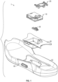
- FIG. 1 is an exploded view illustration of components of a motorized lacing system for footwear, according to some example embodiments.
- the motorized lacing system 1 illustrated in FIG. 1 includes a lacing engine 10, a lid 20, an actuator 30, a mid-sole plate 40, a mid-sole 50, and an outsole 60.
- FIG. 1 illustrates the basic assembly sequence of components of an automated lacing footwear platform.
- the motorized lacing system 1 starts with the mid-sole plate 40 being secured within the mid-sole.
- the actuator 30 is inserted into an opening in the lateral side of the mid-sole plate opposite to interface buttons that can be embedded in the outsole 60.
- the lacing engine 10 is dropped into the mid-sole plate 40.
- the lacing system 1 is inserted under a continuous loop of lacing cable and the lacing cable is aligned with a spool in the lacing engine 10 (discussed below).
- the lid 20 is inserted into grooves in the mid-sole plate 40, secured into a closed position, and latched into a recess in the mid-sole plate 40.
- the lid 20 can capture the lacing engine 10 and can assist in maintaining alignment of a lacing cable during operation.
- the footwear article or the motorized lacing system 1 includes or is configured to interface with one or more sensors that can monitor or determine a foot presence characteristic. Based on information from one or more foot presence sensors, the footwear including the motorized lacing system 1 can be configured to perform various functions.
- a foot presence sensor can be configured to provide binary information about whether a foot is present or not present in the footwear. If a binary signal from the foot presence sensor indicates that a foot is present, then the motorized lacing system 1 can be activated, such as to automatically tighten or relax (i.e., loosen) a footwear lacing cable.
- the footwear article includes a processor circuit that can receive or interpret signals from a foot presence sensor. The processor circuit can optionally be embedded in or with the lacing engine 10, such as in a sole of the footwear article.
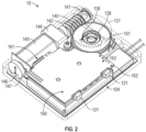
- FIG. 2 is an illustration of various internal components of lacing engine 10, according to example embodiments.
- FIG. 2 also illustrates how a load cell can be incorporated into a lacing engine, such as lacing engine 10.
- the lacing engine 10 further includes spool magnet 136, O-ring seal 138, worm drive 140, bushing 141, worm drive key 142, gear box 144, gear motor 145, motor encoder 146, motor circuit board 147, worm gear 150, circuit board 160, motor header 161, battery connection 162, and wired charging header 163.
- the spool magnet 136 assists in tracking movement of the spool 130 though detection by a magnetometer (not shown in FIG. 2C).
- the O-ring seal 138 functions to seal out dirt and moisture that could migrate into the lacing engine 10 around the spool shaft 133.
- the load cell can be incorporated outboard of bushing 141 to detect forces transmitted from the spool 130 through the worm gear 150 onto the worm drive 140. Information from the load cell can be used as an input to the tension control to tighten or loosen lace tension based on an inference on activity level being experienced by the footwear. For example, if the load cell is detecting frequent shock loading on the laces, it can be inferred that activity level of high (e.g., engaged in basketball game). Alternatively, if the load cell is detecting little or no shock loading, then the lacing engine can infer low activity level and potentially loosen the laces.
- major drive components of the lacing engine 10 include worm drive 140, worm gear 150, gear motor 145 and gear box 144.
- the worm gear 150 is designed to inhibit back driving of worm drive 140 and gear motor 145, which means the major input forces coming in from the lacing cable via the spool 130 are resolved on the comparatively large worm gear and worm drive teeth.
- This arrangement protects the gear box 144 from needing to include gears of sufficient strength to withstand both the dynamic loading from active use of the footwear platform or tightening loading from tightening the lacing system.
- the worm drive 140 includes additional features to assist in protecting the more fragile portions of the drive system, such as the worm drive key 142.
- the worm drive key 142 is a radial slot in the motor end of the worm drive 140 that interfaces with a pin through the drive shaft coming out of the gear box 144.
- This arrangement prevents the worm drive 140 from imparting any axial forces on the gear box 144 or gear motor 145 by allowing the worm drive 140 to move freely in an axial direction (away from the gear box 144) transferring those axial loads onto bushing 141 and the housing structure 100.
- the arrangement also allows for convenience placement of a load cell outboard of the bushing 141 to measure axial forces on the drive training from laces.
- lacing engine 10 Within an automated footwear platform using an automatic lacing engine it may be important to detect various parameters regarding lace position and/or tension.
- the following discusses various concepts for detecting lace position and/or lace tension within a lacing engine, such as lacing engine 10 discussed above.
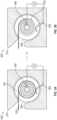
- FIGS. 3A-3B illustrate an electrode technique for directly detecting end of lace travel.
- a flexible electrode is positioned against a portion of the lace spool and impedance is measured across the electrode and spool.
- the impedance will be high, as the lace in this example is an insulator.
- the impedance will drop as the connection improves.
- the end of the lace cable is measured directly through the change in impedance measurement.
- FIG. 3A illustrates the system with some lace on the spool
- FIG. 3B illustrates the system where the lace has run off the spool (at least in the location of the electrode 350).
- the lacing engine 300 includes components such as a housing 310, a lace spool 320, a lace cable 330, a lace end 335, a spool hub 340, and an electrode 350.
- the lace cable 330 is taken up or release by the lace spool 320.
- the electrode 350 measures impedance across a circuit created between the electrode 350 and the lace spool 320.
- the lace spool 320 acts as an electrical conductor and the lace cable 330 acts as an insulator.
- the electrode 350 when there is lace cable wound on the lace spool 320, the electrode 350 is not in contact with the lace spool 320 and the electrical circuit is complete, resulting a high impedance through the circuit.
- the electrode 350 When the lace cable 320 runs off the lace spool 320, the electrode 350 is able to contact the lace spool 320 and complete an electrical circuit. The impedance across this circuit drops when the electrode 350 contacts the lace spool 320, which can be detected by a controller circuit in the lacing engine 310.
- FIG. 3B when the lace end 335 moves past the electrode 350, the electrode 350 comes into contact with the lace spool 340. Once in contact with the conductive lace spool 340, the electrode 350 completes a low impedance electrical circuit.
- the lace cable can be made from a material with a known impedance, which can allow for the electrode 350 to provide data to a controller circuit to approximate the amount of lace cable on the lace spool.
- the width of the lace cable would produce a known impedence level when measured across the circuit produced by the electrode 350 and the lace spool 320.
- Each wrap of lace cable operates to increase the distance between the electrode 350 and the lace spool 320, which would increase the impedance level by a known quantity.
- impedance produced by the lace cable wrapping around the lace spool will not be extremely precise, impedance measurement can be translated into an approximation of the amount of lace cable wrapped around the lace spool.
- the lace spool may be sized in a manner where each wrap of lace cable does not always increase the gap between the electrode and the lace spool by the width of the lace cable, in these examples the impedance measure provides a rougher approximation of lace cable on the lace spool.
- the impedance measurement between the electrode 350 and lace spool 320 can provide aproximations, such as the lace spool is full, 3 ⁇ 4 full, 1 ⁇ 2 full, 1 ⁇ 4 full, or empty.
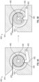
- FIGS. 4A-4B illustrate a lever and divot assembly for detecting lace position (e.g., end of lace travel).
- a spring-loaded lever rides against the lace spool and drops into a divot in the lace spool when the lace runs off the spool.
- a switch or position sensor can detect when the spring-loaded lever drops into the divot.
- FIG. 4A illustrates the interaction between the lever and lace spool prior to the lace end running past the lever.
- FIG. 4B illustrates the condition when the lever drops into the divot after the lace end runs past the lever. The end of travel condition of the lace cable is directly measured by the lever when the lace cable unwraps off the lace spool and allows the lever to drop into the divot in the lace spool.
- the lacing engine 400 can include components such as a housing 410, a lace spool 420, a lace cable 430, a lace end 435, a spool hub 440, a position divot 445, and a lever 450.
- the lever 450 can be spring-loaded and include an integrated cut-off switch to control a motor within the lacing engine.
- the lever 450 pivots on a pivot point 455 integrated into the housing 410.
- the integrated cut-off switch is activated when the lever 450 drops into the divot 445 in the lace spool 420.
- the divot 445 is integrated into the inner surface of the lace spool 420 where the lace cable 430 is taken up.
- the lever 450 With at least one full wrap of lace cable 430 on the lace spool 420, the divot 445 is covered by the lace cable 430, so the lever 450 remains in the normal position with the cut-off switch not activated.
- the lever 450 is free to drop into the divot 445 and activate the cut-off switch stopping the motor.
- the lever 450 is substantially the same width (or depth into the illustration) as the width of the lace spool 420, this allows any amount of lace cable 430 on the lace spool 420 to keep the lever 450 from dropping into the divot 435.
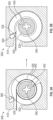
- FIGS. 5A-5B illustrate a split-spool configuration to detect end of lace travel.
- FIG. 5A illustrates the split-spool in a closed state, where there remains lace on the lace spool.
- FIG. 5B illustrates the split-spool in an open state, where the lace has run off the lace spool and causes the hinged (split) portion to extend and activate a cut-off switch.
- the lace spool includes a hinged portion that is held down against the spool when lace is wrapped around the spool. As the lace wraps off the spool, the hinged portion is pulled up into a switch or sensor. Thus, the end of lace travel condition is directly measured or detected when the lace cable pulls the hinged portion off the lace spool and contacts the cut-off switch or sensor.
- the lacing engine 500 can include structures such as a housing 510, a split lace spool 520, a lace cable 530, a lace end 535, a spool hub 540, a hinged portion 550 (also referred to as a split spool section 550), a pivot 555, and a cut-off switch 560.
- the lace cable 530 wraps around the split lace spool 520, which holds the hinged portion 550 in place as the split lace spool 520 rotations about spool hub 540.
- the hinged portion 550 pivots about pivot 555 and contacts cut-off switch 560.
- the hinged portion 550 contacts the cut-off switch 560 the lace spool 520 stops counter-clockwise rotation and any motor input is shut down.
- the lace cable 530 is connected to the hinged portion 550 at lace end 535.
- the lacing engine 500 can reverse (e.g., start clockwise rotation) to take-up lace cable 530 onto the split lace spool 520. Clockwise rotation of the lace spool 520 will cause the hinged portion 550 to pivot back into place on the split lace spool 520, as lace cable 530 is wrapped onto the split lace spool 520.
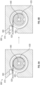
- FIGS. 6A-6B illustrate an optical sensor to detect different markings on a lace cable.
- the lace cable can include characteristics, such as color, pattern, texture, or similar markings, which are detectable by an optical sensor.
- the markings or characteristics can be used to detect certain specific locations on the lace cable, and/or operate like an encoder with markings at regular intervals.
- the optical sensor allows for direct detection or measurement of characteristics of the lace cable as it is manipulated by the lacing engine.
- the lace cable can include alternating (or similar pattern) of different colors that can be detected by an optical sensor. Different colors on various sections of the lace cable can provide a control circuit within an automated lacing engine valuable information about lace travel and/or footwear tightness. For example, using alternating color patterns, a control circuit can receive regular triggers from an optical sensor, which can be used like an encoder signal to track lace cable location (e.g., how much lace cable has been pulled in by the lacing engine).
- the lacing engine 600 can include components such as a housing 610, a lace spool 620, a lace cable 630, a lace end section 635, a spool hub 640, and an optical sensor 660.
- the optical sensor 660 can be utilized to identify transitions between different colored or shaded sections of a lace cable, such as lace cable 620.
- the lace cable 620 is illustrated as having a section of alternating color or shade (shown as alternating shades), as well as a lace end section 635 of a solid color or shade specific to the end of the lace cable.
- the optical sensor 660 is tuned to identify each different transition and color/shade state during operation of the lacing engine 600.
- Data from the optical sensor 660 can be sent to a control circuit, which can use the data to determine amount of lace on the lace spool, speed of lace retraction or extension, or end of lace (e.g., lace end section 635), among other things.
- FIGS. 7A-7B are diagrams illustrating various lace tension detecting assemblies, according to some example embodiments. These example assemblies can be integrated into a lacing engine for an automated footwear platform, such as those discussed above.
- FIG. 7A illustrates a force sensor pulley combination used to detect lace cable tension.
- the lace wraps around (90 degrees) a pin or pulley with a force sensor positioned to sense forces imparted on the pin/pulley by the lace cable.
- the pin/pulley defects under load in a predicable manner, which can then be measured by the force sensor.
- the pin or pulley can be mounted too the force sensor to enable direct detection and/or measurement of the lace cable tension.
- a position sensor is used to detect movement of the pin/pulley, which is then translated into a force.
- the lacing engine 700A can include components such as a housing 710, a spool cavity 715, a lace spool 720, a lace cable 730, a lace free end 735, a pulley 740, and a sensor 750.
- the housing 710 can include a spool cavity 715 designed to receive a lace spool 720, which can be rotated to take-up or release lace cable 730.
- One of the primary functions of a lacing engine, such as lacing engine 700A is to tension a lace cable to secure a footwear platform to a user's foot.
- the senor 750 can detect movement of the pulley (or pin) 740, which can be translated into a force or tension being applied to the lace cable 730.
- the sensor 750 can be a force sensor that directly reads a force being applied against the pulley 740 by the lace cable 730 as it exits the lacing engine 700A.
- the data generated by the sensor 750 can be delivered to a control circuit, which can utilize the data to control tightening or loosening of the lace cable 730 through control of the lacing engine 700A.
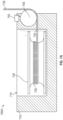
- FIG. 7B illustrates a strain gauge configuration for sensing lace tension.
- a strain gauge can be positions on a bar or structure where the lace exits the lacing engine. The lace can exit the spool and make a 90 degree turn around a structure including the strain gauge. The structure and strain gauge can be calibrated to allow for measurement of the lace tension.
- the lacing engine 700B can include components such as a housing 710, a spool cavity 715, a lace spool 720, a lace cable 730, a lace free end 735, a pulley (or pin) 740, a sensor 750, and a strain gauge 752.
- the lace cable tension is measured by a strain gauge, such as strain gauge 752, on the pin 740.
- a strain gauge such as strain gauge 752
- the tension on the lace cable 730 causes deflection in the pin 740, which is measured by the strain gauge 752.
- the lace cable 730 is taken up by the lace spool 720 as it makes a 90 degree turn around the pin 740.
- the 90 degrees turn around pin 740 imparts sufficient forces against the pin 740 for the strain gauge 752 to measure the defection caused by the tension on lace cable 730.
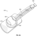
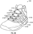
- FIGS. 8A-8B illustrate a direct pressure sensing technique.
- the tongue of a footwear assembly can include one or more force sensing resistors (FSRs).
- the FSRs can detect lace tension across the upper portion of the footwear assembly.
- the FSRs can be positions along the underside of the tongue to press against the foot of the user.
- FIG. 8A illustrates an individual FSR (sensor assembly 810) designed to be positioned at a lace cable junction.
- FIG. 8B illustrates a footwear platform with various FSR locations, such as sensor assembly locations 810A and 810B.
- the sensor assembly 810 can include components such as a sensor platform 815, a lace guide 825, a circuit 830, and a connector 835.
- the sensor platform 815 provides a base for the sensor assembly and it can be designed for integration into various locations within the footwear platform.
- the lace guide 825 can be designed to receive one or more portions of a lace cable and guide the lace cable over the force sensing resistor.
- the circuit 830 can include a calibrated resistor that outputs a resistance measurement that is proportional to an amount of force exerted on the sensor assembly 810.
- the connector 835 is used to interconnect sensor assemblies back to a control circuit within the footwear platform.
- Example 1 describes subject matter including a lacing engine for an automated footwear platform.
- the lacing engine can includes components such as a housing, a lace spool, and a detection mechanism.
- the lace spool can be at least partially disposed within the housing.
- the lace spool can also be adapted to collect a portion of a lace cable in response to rotation in a first direction during tightening of the footwear platform.
- the detection mechanism can directly measure a characteristic of the lace cable while the lace cable is manipulated by the lacing engine.
- Example 2 the subject matter of Example 1 can optionally include the detection mechanism having an electrode adapted to measure an electrical parameter.
- Example 3 the subject matter of Example 2 can optionally include the electrode being adapted to contact a portion of the lace spool with the lace cable is in a first state.
- Example 4 the subject matter of Example 3 can optionally include the electrode completing an electrical circuit through the lace spool when the lace cable is in the first state.
- Example 5 the subject matter of Example 4 can optionally include the electrical circuit exhibiting a low impedance measurement when the lace cable is in the first state.
- Example 6 the subject matter of Example 5 can optionally include the first state of the lace cable being a fully extended state wherein only a portion of the lace spool contacts any lace cable.
- Example 7 the subject matter of any one of Examples 2 to 6 can optionally include the electrode being adapted to contact the lace cable when the lace cable is in a second state.
- Example 8 the subject matter of Example 7 can optionally include a circuit including the electrode and the lace spool, where the circuit exhibits a high impedance measurement when the lace cable is in the second state.
- Example 9 the subject matter of any one of Examples 2 to 8 can optionally include the electrode being spring-loaded to maintain contact against the lace spool with or without lace cable wrapped around the lace spool.
- the electrode can maintain contact throughout a useable range of use for the lace spool (e.g., between a first state (empty) and a second state (full)).
- Example 10 the subject matter of Example 1 can optionally include the detection mechanism including a lever including a free end adapted to follow a contour of the lace spool and a pivot end.
- the detection mechanism including a lever including a free end adapted to follow a contour of the lace spool and a pivot end.
- Example 11 the subject matter of Example 10 can optionally include the lace spool having a divot adapted to receive at least a portion of the free end of the lever.
- Example 12 the subject matter of Example 11 can optionally include the detection mechanism including a sensor to detect when the free end of the lever is received within the divot.
- Example 13 the subject matter of any one of Examples 11 and 12 can optionally include the lace spool being adapted to collect the lace cable upon rotation in a first direction, and where upon collecting at least a first portion of the lace cable the free end of the lever cannot be received within the divot.
- Example 14 the subject matter of any one of Examples 11 to 13 can optionally include the detection mechanism having a cut-off switch activated upon receiving the free end of the lever in the divot.
- Example 15 the subject matter of Example 14 can optionally include the cut-off switch operating to cut-off power to a motor operating the lacing engine.
- Example 16 the subject matter of Example 1 can optionally include the detection mechanism including a cut-off switch and a split portion of the lace spool.
- Example 17 the subject matter of Example 16 can optionally include the split portion of the lace spool having a curved section of the lace spool pivotably coupled to the lace spool.
- Example 18 the subject matter of any one of Examples 16 and 17 can optionally include the lace cable being fixed to a first end of the split portion, wherein the first end is opposite a second end that is pivotably coupled to the lace spool.
- Example 19 the subject matter of any one of Examples 16 to 18 can optionally include the cut-off switch being positioned along the housing such that a first end of the split portion of the lace spool contacts the cut-off switch when the lace cable is in a first state.
- Example 20 the subject matter of any one of Examples 16 to 19 can optionally include, upon the lace cable reaching the first state, continued rotation of the lace spool causing the split portion to pivot radially outward into contact with the cut-off switch.
- Example 21 the subject matter of Example 1 can optionally include the detection mechanism including an optical sensor adapted to sense a characteristic of the lace cable.
- Example 22 the subject matter of Example 21 can optionally include the optical sensor being adapted to sense a transition from a first section of the lace cable to a second section of the lace cable.
- Example 23 the subject matter of Example 22 can optionally include the first section of the lace cable being a first color and the second section of the lace cable being a second color.
- Example 24 the subject matter of Example 23 can optionally include the first section of lace cable having a first pattern within the lace cable and the second section having a second pattern within the lace cable.
- Example 25 the subject matter of any one of Examples 21 to 24 can optionally include the optical sensor being adapted to detect an end portion of the lace cable.
- Example 26 the subject matter of Example 25 can optionally include the end portion of the lace cable having a unique color or a unique pattern in reference to the remainder of the lace cable.
- Example 27 the subject matter of Example 1 can optionally include the detection mechanism including a force sensor to detect tension on the lace cable.
- Example 28 the subject matter of Example 27 can optionally include the detect mechanism including a pin or a pulley receiving a portion of the lace cable.
- Example 29 the subject matter of Example 28 can optionally include the force sensor contacting the pin or the pulley to detect tension transmitted to the pin or the pulley by the portion of the lace cable.
- Example 30 the subject matter of Example 29 can optionally include the portion of the lace cable wraps around 90 degrees of the circumference of the pin or the pulley.
- Example 31 the subject matter of Example 1 can optionally include the detection mechanism including a strain gauge to detect tension on the lace cable.
- Example 32 the subject matter of Example 31 can optionally include the detection mechanism including a pin or a pulley positioned adjacent to the lace spool exit to receive a portion of the lace cable around the circumference of the pin or the pulley.
- the detection mechanism including a pin or a pulley positioned adjacent to the lace spool exit to receive a portion of the lace cable around the circumference of the pin or the pulley.
- Example 33 the subject matter of Example 32 can optionally include the strain gauge being integrated into the pin or the pulley to detect strain induced by tension on the lace cable.
- inventive subject matter has been described with reference to specific example embodiments, various modifications and changes may be made to these embodiments without departing from the broader scope of embodiments of the present disclosure.
- inventive subject matter may be referred to herein, individually or collectively, by the term "invention" merely for convenience and without intending to voluntarily limit the scope of this application to any single disclosure or inventive concept if more than one is, in fact, disclosed.
- the term "or" may be construed in either an inclusive or exclusive sense. Moreover, plural instances may be provided for resources, operations, or structures described herein as a single instance. Additionally, boundaries between various resources, operations, modules, engines, and data stores are somewhat arbitrary, and particular operations are illustrated in a context of specific illustrative configurations. Other allocations of functionality are envisioned and may fall within a scope of various embodiments of the present disclosure. In general, structures and functionality presented as separate resources in the example configurations may be implemented as a combined structure or resource. Similarly, structures and functionality presented as a single resource may be implemented as separate resources. These and other variations, modifications, additions, and improvements fall within a scope of embodiments of the present disclosure as represented by the appended claims. The specification and drawings are, accordingly, to be regarded in an illustrative rather than a restrictive sense.
- Method (process) examples described herein can include machine or robotic implementations at least in part.
Landscapes
- Engineering & Computer Science (AREA)
- General Engineering & Computer Science (AREA)
- Microelectronics & Electronic Packaging (AREA)
- Mechanical Engineering (AREA)
- Health & Medical Sciences (AREA)
- General Health & Medical Sciences (AREA)
- Physical Education & Sports Medicine (AREA)
- Footwear And Its Accessory, Manufacturing Method And Apparatuses (AREA)
- Holders For Apparel And Elements Relating To Apparel (AREA)
Applications Claiming Priority (3)
| Application Number | Priority Date | Filing Date | Title |
|---|---|---|---|
| US201762513213P | 2017-05-31 | 2017-05-31 | |
| EP18810542.3A EP3629821B1 (de) | 2017-05-31 | 2018-05-31 | Systeme, vorrichtungen und techniken zur automatisierten schuhschnürung |
| PCT/US2018/035287 WO2018222805A2 (en) | 2017-05-31 | 2018-05-31 | Automated footwear lacing systems, devices, and techniques |
Related Parent Applications (1)
| Application Number | Title | Priority Date | Filing Date |
|---|---|---|---|
| EP18810542.3A Division EP3629821B1 (de) | 2017-05-31 | 2018-05-31 | Systeme, vorrichtungen und techniken zur automatisierten schuhschnürung |
Publications (2)
| Publication Number | Publication Date |
|---|---|
| EP4454512A2 true EP4454512A2 (de) | 2024-10-30 |
| EP4454512A3 EP4454512A3 (de) | 2024-11-27 |
Family
ID=64455098
Family Applications (6)
| Application Number | Title | Priority Date | Filing Date |
|---|---|---|---|
| EP24200161.8A Pending EP4454512A3 (de) | 2017-05-31 | 2018-05-31 | Systeme, vorrichtungen und techniken zur automatisierten schnürung von schuhwerk |
| EP24182503.3A Pending EP4437899A3 (de) | 2017-05-31 | 2018-05-31 | Systeme, vorrichtungen und techniken zur automatisierten schnürung von schuhwerk |
| EP22184045.7A Active EP4129108B1 (de) | 2017-05-31 | 2018-05-31 | Systeme, vorrichtungen und techniken zur automatisierten schuhschnürung |
| EP18809615.0A Active EP3629819B1 (de) | 2017-05-31 | 2018-05-31 | Systeme, vorrichtungen und techniken zur automatisierten schuhschnürung |
| EP18810542.3A Active EP3629821B1 (de) | 2017-05-31 | 2018-05-31 | Systeme, vorrichtungen und techniken zur automatisierten schuhschnürung |
| EP18810465.7A Active EP3629820B1 (de) | 2017-05-31 | 2018-05-31 | Systeme zur automatisierten schuhschnürung |
Family Applications After (5)
| Application Number | Title | Priority Date | Filing Date |
|---|---|---|---|
| EP24182503.3A Pending EP4437899A3 (de) | 2017-05-31 | 2018-05-31 | Systeme, vorrichtungen und techniken zur automatisierten schnürung von schuhwerk |
| EP22184045.7A Active EP4129108B1 (de) | 2017-05-31 | 2018-05-31 | Systeme, vorrichtungen und techniken zur automatisierten schuhschnürung |
| EP18809615.0A Active EP3629819B1 (de) | 2017-05-31 | 2018-05-31 | Systeme, vorrichtungen und techniken zur automatisierten schuhschnürung |
| EP18810542.3A Active EP3629821B1 (de) | 2017-05-31 | 2018-05-31 | Systeme, vorrichtungen und techniken zur automatisierten schuhschnürung |
| EP18810465.7A Active EP3629820B1 (de) | 2017-05-31 | 2018-05-31 | Systeme zur automatisierten schuhschnürung |
Country Status (4)
| Country | Link |
|---|---|
| US (6) | US11717055B2 (de) |
| EP (6) | EP4454512A3 (de) |
| CN (6) | CN113662314B (de) |
| WO (3) | WO2018222807A2 (de) |
Families Citing this family (32)
| Publication number | Priority date | Publication date | Assignee | Title |
|---|---|---|---|---|
| US10852069B2 (en) | 2010-05-04 | 2020-12-01 | Fractal Heatsink Technologies, LLC | System and method for maintaining efficiency of a fractal heat sink |
| US11103030B2 (en) | 2015-10-07 | 2021-08-31 | Puma SE | Article of footwear having an automatic lacing system |
| US11185130B2 (en) | 2015-10-07 | 2021-11-30 | Puma SE | Article of footwear having an automatic lacing system |
| US11033079B2 (en) | 2015-10-07 | 2021-06-15 | Puma SE | Article of footwear having an automatic lacing system |
| KR102472201B1 (ko) | 2015-12-02 | 2022-11-29 | 푸마 에스이 | 신발, 특히 운동화를 레이싱하는 방법 |
| US10390589B2 (en) | 2016-03-15 | 2019-08-27 | Nike, Inc. | Drive mechanism for automated footwear platform |
| CN113508961B (zh) * | 2016-03-15 | 2023-03-31 | 耐克创新有限合伙公司 | 用于鞋类的机动化张紧系统的传动装置 |
| AU2016430821A1 (en) | 2016-11-22 | 2019-06-13 | Puma SE | Method for fastening a shoe, in particular a sports shoe, and shoe, in particular sports shoe |
| RU2715263C1 (ru) | 2016-11-22 | 2020-02-26 | Пума Се | Способ надевания или снятия предмета одежды на его носчика или с его носчика или способ закрывания, надевания, открывания или снятия носимого человеком предмета багажа |
| US11564452B2 (en) * | 2016-12-09 | 2023-01-31 | Adamant Namiki Precision Jewel Co., Ltd. | Winding device |
| CN107070080B (zh) * | 2017-03-31 | 2019-02-01 | 深圳市索拉太阳能有限公司 | 一种用于休闲鞋的高能发电装置 |
| EP4454512A3 (de) | 2017-05-31 | 2024-11-27 | Nike Innovate C.V. | Systeme, vorrichtungen und techniken zur automatisierten schnürung von schuhwerk |
| US10667580B2 (en) * | 2017-10-11 | 2020-06-02 | Under Armour, Inc. | Lace tightening mechanism and parameter detector disposed therein |
| CN114145546A (zh) * | 2017-10-20 | 2022-03-08 | 耐克创新有限合伙公司 | 用于自动鞋类平台的支撑结构 |
| WO2020047450A1 (en) * | 2018-08-31 | 2020-03-05 | Nike Innovate C.V. | Autolacing footwear having a notched spool |
| US11684110B2 (en) * | 2018-08-31 | 2023-06-27 | Nike, Inc. | Autolacing footwear |
| KR102898772B1 (ko) | 2018-11-30 | 2025-12-10 | 나이키 이노베이트 씨.브이. | 전동식 레이싱 시스템 |
| USD889805S1 (en) | 2019-01-30 | 2020-07-14 | Puma SE | Shoe |
| USD899053S1 (en) | 2019-01-30 | 2020-10-20 | Puma SE | Shoe |
| USD906657S1 (en) | 2019-01-30 | 2021-01-05 | Puma SE | Shoe tensioning device |
| CN114080167B (zh) * | 2019-04-23 | 2024-07-19 | 彪马欧洲公司 | 具有自动系带系统的鞋类物品 |
| EP4013297A4 (de) | 2019-08-16 | 2023-12-13 | Poltorak Technologies, LLC | Vorrichtung und verfahren für medizinische diagnostik |
| US11484089B2 (en) | 2019-10-21 | 2022-11-01 | Puma SE | Article of footwear having an automatic lacing system with integrated sound damping |
| CN113942891B (zh) * | 2020-07-17 | 2024-04-26 | 苏州星诺奇科技股份有限公司 | 绳带松紧组件的制造方法及可穿戴制品的制造方法 |
| US20220110401A1 (en) * | 2020-10-13 | 2022-04-14 | Nike, Inc. | Article of Footwear |
| CN112167934B (zh) * | 2020-10-16 | 2022-05-06 | 杭州星吉信息咨询有限公司 | 一种系鞋带设备 |
| JP7499153B2 (ja) | 2020-11-04 | 2024-06-13 | 朝日インテック株式会社 | 巻取装置、ベルト及び衣類 |
| JP2022090802A (ja) * | 2020-12-08 | 2022-06-20 | 日本電産株式会社 | レーシングモジュール |
| CN112744648A (zh) * | 2021-01-21 | 2021-05-04 | 谭书涛 | 一种柔性多圈转角限位结构及自动绕线模块 |
| US12121366B2 (en) * | 2021-02-12 | 2024-10-22 | The Board Of Trustees Of The University Of Alabama | Sensorized shoelace-tensioning system and method |
| CN113303556B (zh) * | 2021-06-05 | 2025-06-24 | 南京沐瑶信息科技有限公司 | 一种电动系鞋带传动装置 |
| US12171306B2 (en) | 2021-11-16 | 2024-12-24 | Puma SE | Article of footwear having an automatic lacing system |
Family Cites Families (104)
| Publication number | Priority date | Publication date | Assignee | Title |
|---|---|---|---|---|
| US5117893A (en) * | 1985-08-07 | 1992-06-02 | Excel Shutter Systems, Inc. | Rolling shutter system |
| IT1210449B (it) * | 1987-05-15 | 1989-09-14 | Nordica Spa | Dispositivo di serraggio e regolazione particolarmente per scarponi da sci. |
| AT392334B (de) * | 1988-08-08 | 1991-03-11 | Dynafit Gmbh | Wickelvorrichtung fuer seilzuege, insbesondere fuer skischuhe |
| DE3913018A1 (de) | 1989-04-20 | 1990-10-25 | Weinmann & Co Kg | Drehverschluss fuer einen sportschuh, insbesondere einen skischuh |
| DE4240916C1 (de) * | 1992-12-04 | 1993-10-07 | Jungkind Roland | Schuhverschluß |
| DE4302401A1 (de) * | 1993-01-28 | 1994-08-04 | Egolf Heinz | Drehverschluß |
| DE4303569C1 (de) | 1993-02-08 | 1994-03-03 | Jungkind Roland | Zentralverschluß für Schuhe |
| JP3165581B2 (ja) | 1994-04-11 | 2001-05-14 | 株式会社ケット科学研究所 | 穀類水分計の電極装置 |
| US5934599A (en) * | 1997-08-22 | 1999-08-10 | Hammerslag; Gary R. | Footwear lacing system |
| US6289558B1 (en) * | 1997-08-22 | 2001-09-18 | Boa Technology, Inc. | Footwear lacing system |
| US20060156517A1 (en) | 1997-08-22 | 2006-07-20 | Hammerslag Gary R | Reel based closure system |
| US7591050B2 (en) | 1997-08-22 | 2009-09-22 | Boa Technology, Inc. | Footwear lacing system |
| US20020095750A1 (en) * | 1997-08-22 | 2002-07-25 | Hammerslag Gary R. | Footwear lacing system |
| US6032387A (en) * | 1998-03-26 | 2000-03-07 | Johnson; Gregory G. | Automated tightening and loosening shoe |
| US7096559B2 (en) | 1998-03-26 | 2006-08-29 | Johnson Gregory G | Automated tightening shoe and method |
| TW521593U (en) | 2002-02-08 | 2003-02-21 | Kuen-Jung Liou | Shoes capable of being tightened electrically |
| KR200317479Y1 (ko) | 2003-03-20 | 2003-06-25 | 안영기 | 신발끈 결속장치 |
| US6694643B1 (en) * | 2003-04-07 | 2004-02-24 | Cheng-Hui Hsu | Shoelace adjustment mechanism |
| CN2613167Y (zh) | 2003-05-14 | 2004-04-28 | 李伊勇 | 一种系鞋带器 |
| JP2005124597A (ja) * | 2003-10-21 | 2005-05-19 | Satoki Sakabayashi | 靴紐締結装置 |
| US7076843B2 (en) | 2003-10-21 | 2006-07-18 | Toshiki Sakabayashi | Shoestring tying apparatus |
| US7017846B2 (en) * | 2004-02-20 | 2006-03-28 | Comstar Communications Ltd. | Retractable cable winder |
| US7516914B2 (en) * | 2004-05-07 | 2009-04-14 | Enventys, Llc | Bi-directional device |
| JP4874986B2 (ja) * | 2004-10-29 | 2012-02-15 | ボア テクノロジイ インコーポレイテッド | ケーブル締め付け機構およびその付勢方法 |
| US7662122B2 (en) * | 2005-03-07 | 2010-02-16 | Bellacure, Inc. | Orthotic or prosthetic devices with adjustable force dosimeter and sensor |
| DE102005037967A1 (de) * | 2005-08-11 | 2007-02-15 | Head Germany Gmbh | Drehverschluss für einen Schuh |
| US7721468B1 (en) | 2005-08-26 | 2010-05-25 | Gregory G. Johnson | Tightening shoe |
| US7367522B2 (en) * | 2005-10-14 | 2008-05-06 | Chin Chu Chen | String fastening device |
| US8277401B2 (en) * | 2006-09-12 | 2012-10-02 | Boa Technology, Inc. | Closure system for braces, protective wear and similar articles |
| US7617573B2 (en) * | 2007-01-18 | 2009-11-17 | Chin-Chu Chen | Shoelace fastening assembly |
| US7584528B2 (en) * | 2007-02-20 | 2009-09-08 | Meng Hann Plastic Co., Ltd. | Shoelace reel operated easily and conveniently |
| US7752774B2 (en) | 2007-06-05 | 2010-07-13 | Tim James Ussher | Powered shoe tightening with lace cord guiding system |
| US7676957B2 (en) | 2007-06-14 | 2010-03-16 | Johnson Gregory G | Automated tightening shoe |
| US11206891B2 (en) * | 2008-05-02 | 2021-12-28 | Nike, Inc. | Article of footwear and a method of assembly of the article of footwear |
| US8046937B2 (en) * | 2008-05-02 | 2011-11-01 | Nike, Inc. | Automatic lacing system |
| US8056269B2 (en) * | 2008-05-02 | 2011-11-15 | Nike, Inc. | Article of footwear with lighting system |
| US10070680B2 (en) * | 2008-06-13 | 2018-09-11 | Nike, Inc. | Footwear having sensor system |
| EP2306859A1 (de) * | 2008-07-10 | 2011-04-13 | Frans Voskuil | Zieraufsatz für fussbekleidung |
| WO2010059989A2 (en) | 2008-11-21 | 2010-05-27 | Boa Technology, Inc. | Reel based lacing system |
| US8245371B2 (en) * | 2009-04-01 | 2012-08-21 | Chin Chu Chen | String securing device |
| TW201127310A (en) * | 2010-02-11 | 2011-08-16 | jin-zhu Chen | Step-less finetuning buckle |
| US8707486B2 (en) * | 2010-02-16 | 2014-04-29 | Allen Medical Systems, Inc. | Lacing system to secure a limb in a surgical support apparatus |
| KR102128867B1 (ko) | 2010-04-30 | 2020-07-01 | 보아 테크놀러지, 인크. | 릴 기반 끈 조임 시스템 |
| US10070695B2 (en) * | 2010-04-30 | 2018-09-11 | Boa Technology Inc. | Tightening mechanisms and applications including the same |
| US8231074B2 (en) * | 2010-06-10 | 2012-07-31 | Hu rong-fu | Lace winding device for shoes |
| TWM402008U (en) | 2010-06-23 | 2011-04-21 | jin-zhu Chen | Shoelace device |
| CN103228235B (zh) * | 2010-07-01 | 2017-09-15 | 3M创新有限公司 | 使用紧束系统的护具 |
| IT1403347B1 (it) * | 2010-12-03 | 2013-10-17 | Geox Spa | Dispositivo di bloccaggio per lacci, stringhe, corde e simili, particolarmente atti alla chiusura di calzature, zaini, capi di abbigliamento e simili |
| CN103442669B (zh) * | 2011-02-10 | 2015-09-16 | 奥索有限责任公司 | 用于矫形制品的收紧系统 |
| US8353087B2 (en) * | 2011-03-07 | 2013-01-15 | Chin-Chu Chen | Closure device |
| EP2529777A1 (de) | 2011-05-30 | 2012-12-05 | Sanofi-Aventis Deutschland GmbH | Vorrichtung zur Entfernung einer Nadelanordnung |
| US9101181B2 (en) * | 2011-10-13 | 2015-08-11 | Boa Technology Inc. | Reel-based lacing system |
| US8935860B2 (en) * | 2011-10-28 | 2015-01-20 | George Torres | Self-tightening shoe |
| US11071344B2 (en) * | 2012-02-22 | 2021-07-27 | Nike, Inc. | Motorized shoe with gesture control |
| US9241539B1 (en) * | 2012-06-29 | 2016-01-26 | Jeffrey Keswin | Shoelace tightening method and apparatus |
| CN104582519B (zh) | 2012-08-31 | 2016-08-24 | 耐克创新有限合伙公司 | 机动张紧系统 |
| US9365387B2 (en) * | 2012-08-31 | 2016-06-14 | Nike, Inc. | Motorized tensioning system with sensors |
| US9578926B2 (en) | 2012-12-17 | 2017-02-28 | Vibralabs Incorporated | Device for automatically tightening and loosening laces |
| TWI482599B (zh) | 2013-01-22 | 2015-05-01 | Tzy Shenq Entpr Co Ltd | 鞋帶調整器 |
| US9629417B2 (en) * | 2013-07-02 | 2017-04-25 | Boa Technology Inc. | Tension limiting mechanisms for closure devices and methods therefor |
| EP3019043B1 (de) * | 2013-07-10 | 2019-09-18 | Boa Technology Inc. | Verschlussvorrichtungen mit inkrementellen lösemechanismen und verfahren dafür |
| US9491983B2 (en) * | 2013-08-19 | 2016-11-15 | Nike, Inc. | Article of footwear with adjustable sole |
| US10645990B2 (en) | 2013-08-19 | 2020-05-12 | Nike, Inc. | Article of footwear with adjustable sole |
| KR20250004049A (ko) * | 2013-09-13 | 2025-01-07 | 보아 테크놀러지, 인크. | 릴 기반 폐쇄 장치 및 그에 따른 방법 |
| EP3046434B1 (de) | 2013-09-20 | 2019-05-22 | NIKE Innovate C.V. | Schuhwerk mit abnehmbarem motorisiertem einstellsystem |
| WO2015054722A1 (en) | 2013-10-14 | 2015-04-23 | Mahe Falekava F | A shoe lace fastening and locking device |
| TWI561453B (en) | 2014-02-17 | 2016-12-11 | Chin Chu Chen | A device for tightening and loosening a lace |
| US9326566B2 (en) * | 2014-04-15 | 2016-05-03 | Nike, Inc. | Footwear having coverable motorized adjustment system |
| KR101572647B1 (ko) | 2014-05-15 | 2015-12-11 | (주)경도상사 | 잠금커버가 구비된 신발끈 조임장치 |
| CN104585975A (zh) | 2014-05-22 | 2015-05-06 | 郑君 | 自动绑紧和松开系带的装置 |
| CN203952623U (zh) * | 2014-07-18 | 2014-11-26 | 陈祈勋 | 收束物系绑装置 |
| US10231505B2 (en) * | 2015-05-28 | 2019-03-19 | Nike, Inc. | Article of footwear and a charging system for an article of footwear |
| US10292451B2 (en) * | 2015-05-28 | 2019-05-21 | Nike, Inc. | Sole plate for an article of footwear |
| US10743620B2 (en) | 2015-05-28 | 2020-08-18 | Nike, Inc. | Automated tensioning system for an article of footwear |
| KR102595025B1 (ko) | 2015-05-29 | 2023-10-26 | 나이키 이노베이트 씨.브이. | 소형 스풀 시스템을 가지는 동력형 장력화 장치 |
| CN107847016B (zh) * | 2015-05-29 | 2020-11-27 | 耐克创新有限合伙公司 | 包含具有分离线轴系统的机动张紧装置的鞋类物品 |
| FR3038815B1 (fr) * | 2015-07-17 | 2017-08-25 | Digit Solutions | Chaussure a lacage automatique |
| EP3358981B1 (de) * | 2015-10-07 | 2019-07-17 | Puma Se | Schuh, insbesondere sportschuh |
| KR102472201B1 (ko) * | 2015-12-02 | 2022-11-29 | 푸마 에스이 | 신발, 특히 운동화를 레이싱하는 방법 |
| US10660406B2 (en) * | 2016-03-15 | 2020-05-26 | Nike, Inc. | Tensioning system and reel member for footwear |
| US10390589B2 (en) * | 2016-03-15 | 2019-08-27 | Nike, Inc. | Drive mechanism for automated footwear platform |
| US10827804B2 (en) * | 2016-03-15 | 2020-11-10 | Nike, Inc. | Lacing apparatus for automated footwear platform |
| US10342293B2 (en) * | 2016-03-15 | 2019-07-09 | Nike, Inc. | Method of forming an aperture in a reel member of a tensioning system for an article of footwear |
| CN113508961B (zh) * | 2016-03-15 | 2023-03-31 | 耐克创新有限合伙公司 | 用于鞋类的机动化张紧系统的传动装置 |
| US11026481B2 (en) * | 2016-03-15 | 2021-06-08 | Nike, Inc. | Foot presence signal processing using velocity |
| US10238180B2 (en) * | 2016-03-15 | 2019-03-26 | Nike, Inc. | Position sensing assembly for a tensioning system |
| US10244822B2 (en) * | 2016-03-15 | 2019-04-02 | Nike, Inc. | Lace routing pattern of a lacing system for an article of footwear |
| US11064768B2 (en) * | 2016-03-15 | 2021-07-20 | Nike, Inc. | Foot presence signal processing using velocity |
| EP3429406B1 (de) * | 2016-03-15 | 2025-06-25 | NIKE Innovate C.V. | Kapazitiver fusspräsenzsensor für schuhwerk |
| WO2018170148A2 (en) * | 2016-03-15 | 2018-09-20 | Walker Steven H | Foot presence signal processing using velocity |
| US10201212B2 (en) * | 2016-03-15 | 2019-02-12 | Nike, Inc. | Article of footwear with a tensioning system including a guide assembly |
| CN105581438B (zh) * | 2016-03-18 | 2018-03-30 | 黄逢春 | 一种可自动调节鞋带松紧的鞋 |
| US10624423B2 (en) * | 2016-05-18 | 2020-04-21 | Nike, Inc. | Article of footwear with a pulley system having a guide portion |
| US10834999B2 (en) * | 2016-05-18 | 2020-11-17 | Nike, Inc. | Article of footwear with a pulley system |
| CN205902893U (zh) * | 2016-06-20 | 2017-01-25 | 天津联鑫源制鞋有限公司 | 一种运动鞋的自动系紧按扣 |
| US11026472B2 (en) * | 2016-07-22 | 2021-06-08 | Nike, Inc. | Dynamic lacing system |
| CN106108217A (zh) * | 2016-08-19 | 2016-11-16 | 安徽诺豪鞋业有限公司 | 一种自动系鞋带的鞋 |
| KR102591493B1 (ko) * | 2017-01-26 | 2023-10-18 | 전효석 | 끈 조절 장치 |
| EP4454512A3 (de) | 2017-05-31 | 2024-11-27 | Nike Innovate C.V. | Systeme, vorrichtungen und techniken zur automatisierten schnürung von schuhwerk |
| US10575592B1 (en) * | 2018-03-14 | 2020-03-03 | Charles M Jones | Lace tightening apparatus and method |
| DE202019005973U1 (de) * | 2018-09-06 | 2023-09-26 | Nike Innovate C.V. | Dynamisches Schnürsystem mit Rückmeldungsmechanismus |
| WO2020061170A1 (en) * | 2018-09-19 | 2020-03-26 | Nike Innovate C.V. | Zonal dynamic lacing system |
| CN115697127A (zh) * | 2020-04-27 | 2023-02-03 | 耐克创新有限合伙公司 | 用于鞋类物品的张紧系统 |
| US20220110401A1 (en) * | 2020-10-13 | 2022-04-14 | Nike, Inc. | Article of Footwear |
-
2018
- 2018-05-31 EP EP24200161.8A patent/EP4454512A3/de active Pending
- 2018-05-31 WO PCT/US2018/035289 patent/WO2018222807A2/en not_active Ceased
- 2018-05-31 CN CN202110936034.1A patent/CN113662314B/zh active Active
- 2018-05-31 WO PCT/US2018/035287 patent/WO2018222805A2/en not_active Ceased
- 2018-05-31 CN CN201880048164.8A patent/CN111629625B/zh active Active
- 2018-05-31 US US15/993,905 patent/US11717055B2/en active Active
- 2018-05-31 EP EP24182503.3A patent/EP4437899A3/de active Pending
- 2018-05-31 EP EP22184045.7A patent/EP4129108B1/de active Active
- 2018-05-31 CN CN202210367249.0A patent/CN115104810B/zh active Active
- 2018-05-31 EP EP18809615.0A patent/EP3629819B1/de active Active
- 2018-05-31 US US15/993,914 patent/US11559108B2/en active Active
- 2018-05-31 US US15/993,904 patent/US11707115B2/en active Active
- 2018-05-31 WO PCT/US2018/035341 patent/WO2018222836A2/en not_active Ceased
- 2018-05-31 EP EP18810542.3A patent/EP3629821B1/de active Active
- 2018-05-31 CN CN201880048319.8A patent/CN111615344B/zh active Active
- 2018-05-31 CN CN201880048175.6A patent/CN111315249B/zh active Active
- 2018-05-31 CN CN202111515691.5A patent/CN114304812B/zh active Active
- 2018-05-31 EP EP18810465.7A patent/EP3629820B1/de active Active
-
2022
- 2022-12-27 US US18/089,097 patent/US11903452B2/en active Active
-
2023
- 2023-06-08 US US18/207,517 patent/US12133575B2/en active Active
- 2023-08-07 US US18/230,842 patent/US12137774B2/en active Active
Also Published As
Similar Documents
| Publication | Publication Date | Title |
|---|---|---|
| US12133575B2 (en) | Automated footwear lacing systems, devices, and techniques | |
| US12075889B2 (en) | Box lacing channel for automated footwear platform | |
| CN109152443B (zh) | 用于自动化鞋类平台的致动器 |
Legal Events
| Date | Code | Title | Description |
|---|---|---|---|
| PUAI | Public reference made under article 153(3) epc to a published international application that has entered the european phase |
Free format text: ORIGINAL CODE: 0009012 |
|
| STAA | Information on the status of an ep patent application or granted ep patent |
Free format text: STATUS: THE APPLICATION HAS BEEN PUBLISHED |
|
| PUAL | Search report despatched |
Free format text: ORIGINAL CODE: 0009013 |
|
| AC | Divisional application: reference to earlier application |
Ref document number: 3629821 Country of ref document: EP Kind code of ref document: P |
|
| AK | Designated contracting states |
Kind code of ref document: A2 Designated state(s): AL AT BE BG CH CY CZ DE DK EE ES FI FR GB GR HR HU IE IS IT LI LT LU LV MC MK MT NL NO PL PT RO RS SE SI SK SM TR |
|
| AK | Designated contracting states |
Kind code of ref document: A3 Designated state(s): AL AT BE BG CH CY CZ DE DK EE ES FI FR GB GR HR HU IE IS IT LI LT LU LV MC MK MT NL NO PL PT RO RS SE SI SK SM TR |
|
| RIC1 | Information provided on ipc code assigned before grant |
Ipc: A43B 3/34 20220101ALI20241022BHEP Ipc: A43C 1/00 20060101ALI20241022BHEP Ipc: A43B 13/14 20060101ALI20241022BHEP Ipc: A43B 3/00 20220101ALI20241022BHEP Ipc: A43C 11/14 20060101ALI20241022BHEP Ipc: A43C 7/08 20060101ALI20241022BHEP Ipc: A43C 11/00 20060101ALI20241022BHEP Ipc: A43C 11/16 20060101AFI20241022BHEP |
|
| STAA | Information on the status of an ep patent application or granted ep patent |
Free format text: STATUS: REQUEST FOR EXAMINATION WAS MADE |
|
| 17P | Request for examination filed |
Effective date: 20250527 |
|
| P01 | Opt-out of the competence of the unified patent court (upc) registered |
Free format text: CASE NUMBER: APP_24993/2025 Effective date: 20250526 |
|
| GRAP | Despatch of communication of intention to grant a patent |
Free format text: ORIGINAL CODE: EPIDOSNIGR1 |
|
| STAA | Information on the status of an ep patent application or granted ep patent |
Free format text: STATUS: GRANT OF PATENT IS INTENDED |
|
| INTG | Intention to grant announced |
Effective date: 20250818 |
|
| GRAJ | Information related to disapproval of communication of intention to grant by the applicant or resumption of examination proceedings by the epo deleted |
Free format text: ORIGINAL CODE: EPIDOSDIGR1 |
|
| STAA | Information on the status of an ep patent application or granted ep patent |
Free format text: STATUS: REQUEST FOR EXAMINATION WAS MADE |
|
| GRAP | Despatch of communication of intention to grant a patent |
Free format text: ORIGINAL CODE: EPIDOSNIGR1 |
|
| INTC | Intention to grant announced (deleted) | ||
| STAA | Information on the status of an ep patent application or granted ep patent |
Free format text: STATUS: GRANT OF PATENT IS INTENDED |