EP4450742A1 - Band für eine tür oder ein fenster - Google Patents
Band für eine tür oder ein fenster Download PDFInfo
- Publication number
- EP4450742A1 EP4450742A1 EP24169219.3A EP24169219A EP4450742A1 EP 4450742 A1 EP4450742 A1 EP 4450742A1 EP 24169219 A EP24169219 A EP 24169219A EP 4450742 A1 EP4450742 A1 EP 4450742A1
- Authority
- EP
- European Patent Office
- Prior art keywords
- hinge
- tab
- hinge tab
- clamping part
- leaf
- Prior art date
- Legal status (The legal status is an assumption and is not a legal conclusion. Google has not performed a legal analysis and makes no representation as to the accuracy of the status listed.)
- Granted
Links
Images

Classifications
-
- E—FIXED CONSTRUCTIONS
- E05—LOCKS; KEYS; WINDOW OR DOOR FITTINGS; SAFES
- E05D—HINGES OR SUSPENSION DEVICES FOR DOORS, WINDOWS OR WINGS
- E05D7/00—Hinges or pivots of special construction
- E05D7/12—Hinges or pivots of special construction to allow easy detachment of the hinge from the wing or the frame
-
- E—FIXED CONSTRUCTIONS
- E05—LOCKS; KEYS; WINDOW OR DOOR FITTINGS; SAFES
- E05D—HINGES OR SUSPENSION DEVICES FOR DOORS, WINDOWS OR WINGS
- E05D5/00—Construction of single parts, e.g. the parts for attachment
- E05D5/02—Parts for attachment, e.g. flaps
- E05D5/06—Bent flaps
- E05D2005/067—Bent flaps gooseneck shaped
-
- E—FIXED CONSTRUCTIONS
- E05—LOCKS; KEYS; WINDOW OR DOOR FITTINGS; SAFES
- E05D—HINGES OR SUSPENSION DEVICES FOR DOORS, WINDOWS OR WINGS
- E05D7/00—Hinges or pivots of special construction
- E05D7/12—Hinges or pivots of special construction to allow easy detachment of the hinge from the wing or the frame
- E05D2007/128—Hinges or pivots of special construction to allow easy detachment of the hinge from the wing or the frame in a radial direction
-
- E—FIXED CONSTRUCTIONS
- E05—LOCKS; KEYS; WINDOW OR DOOR FITTINGS; SAFES
- E05Y—INDEXING SCHEME ASSOCIATED WITH SUBCLASSES E05D AND E05F, RELATING TO CONSTRUCTION ELEMENTS, ELECTRIC CONTROL, POWER SUPPLY, POWER SIGNAL OR TRANSMISSION, USER INTERFACES, MOUNTING OR COUPLING, DETAILS, ACCESSORIES, AUXILIARY OPERATIONS NOT OTHERWISE PROVIDED FOR, APPLICATION THEREOF
- E05Y2201/00—Constructional elements; Accessories therefor
- E05Y2201/40—Motors; Magnets; Springs; Weights; Accessories therefor
- E05Y2201/47—Springs
- E05Y2201/48—Leaf or leg springs
-
- E—FIXED CONSTRUCTIONS
- E05—LOCKS; KEYS; WINDOW OR DOOR FITTINGS; SAFES
- E05Y—INDEXING SCHEME ASSOCIATED WITH SUBCLASSES E05D AND E05F, RELATING TO CONSTRUCTION ELEMENTS, ELECTRIC CONTROL, POWER SUPPLY, POWER SIGNAL OR TRANSMISSION, USER INTERFACES, MOUNTING OR COUPLING, DETAILS, ACCESSORIES, AUXILIARY OPERATIONS NOT OTHERWISE PROVIDED FOR, APPLICATION THEREOF
- E05Y2600/00—Mounting or coupling arrangements for elements provided for in this subclass
- E05Y2600/50—Mounting methods; Positioning
- E05Y2600/52—Toolless
- E05Y2600/53—Snapping
-
- E—FIXED CONSTRUCTIONS
- E05—LOCKS; KEYS; WINDOW OR DOOR FITTINGS; SAFES
- E05Y—INDEXING SCHEME ASSOCIATED WITH SUBCLASSES E05D AND E05F, RELATING TO CONSTRUCTION ELEMENTS, ELECTRIC CONTROL, POWER SUPPLY, POWER SIGNAL OR TRANSMISSION, USER INTERFACES, MOUNTING OR COUPLING, DETAILS, ACCESSORIES, AUXILIARY OPERATIONS NOT OTHERWISE PROVIDED FOR, APPLICATION THEREOF
- E05Y2600/00—Mounting or coupling arrangements for elements provided for in this subclass
- E05Y2600/60—Mounting or coupling members; Accessories therefor
-
- E—FIXED CONSTRUCTIONS
- E05—LOCKS; KEYS; WINDOW OR DOOR FITTINGS; SAFES
- E05Y—INDEXING SCHEME ASSOCIATED WITH SUBCLASSES E05D AND E05F, RELATING TO CONSTRUCTION ELEMENTS, ELECTRIC CONTROL, POWER SUPPLY, POWER SIGNAL OR TRANSMISSION, USER INTERFACES, MOUNTING OR COUPLING, DETAILS, ACCESSORIES, AUXILIARY OPERATIONS NOT OTHERWISE PROVIDED FOR, APPLICATION THEREOF
- E05Y2900/00—Application of doors, windows, wings or fittings thereof
- E05Y2900/10—Application of doors, windows, wings or fittings thereof for buildings or parts thereof
- E05Y2900/13—Type of wing
- E05Y2900/132—Doors
Definitions
- the subject matter of the invention is a hinge for a door or a window according to the preamble of claim 1.
- the hinge consists of a frame part and a sash part.
- the sash part and the frame part are mounted separately on the sash and frame.
- the frame part consists of a fastening section and a coupling piece articulated to it.
- the coupling piece has a hinge tab, which is flat and rectangular in the form of a tongue with a tapered end and two holding recesses with open edges on opposite parallel side edges. Hinge pockets are attached to the sash in recesses. To attach the sash to the frame, the hinge pockets, which can be moved together with the sash, are slipped over the hinge tabs and the sash is then lowered.
- the holding projection can be moved horizontally using an adjusting device so that the hinge tab can be adjusted relative to the hinge pocket. As long as the sash presses the hinge pocket with the holding projection into the holding recess using its weight, the sash is secured.
- an anti-lift device is provided.
- a hinge holder PFVP7000 is used.
- the anti-lift device here consists of a cover plate attached to the front at the lower end of the hinge pocket, a section of which protrudes into the opening of the hinge pocket and partially closes it. This means that the hinge flap can hit the cover plate when the sash is lifted, which prevents it from being lifted any further.
- the cover plate must be attached manually.
- the EP 3529440 B1 a clamping part which is mounted in the hinge pocket so that it can move in the direction of insertion of the hinge flap against a spring force. If the sash with hinge pockets is pushed over the hinge flaps, the hinge flap pushes the clamping part in the pocket backwards into the hinge pocket. If the sash is lowered, the hinge flap releases the clamping part, which is pushed in the direction of the fold due to the spring force. The clamping part then grips under the hinge flap with a key-bit-like projection. This limits the movement of the hinge flap in the hinge pocket.
- the clamping part must be guided in a guide in the hinge pocket so that it can move.
- the clamping part therefore has the cross-sectional shape of a key with a bit.
- the cylindrical section forms the Guide of the clamping part and on this acts the compression spring, which must also be accommodated in the guide.
- the design therefore consists of at least the spring and the clamping part.
- the movable clamping part must be mounted in the guide and requires additional space behind the hinge pocket. Since the guide and the clamping part are attached to the lower end of the hinge pocket, dirt and abrasion can impair the mobility of the clamping part.
- the design requires considerable effort during assembly and has the disadvantage that the clamping part in the previously described embodiment supports the hinge flap over a small part of its length. To prevent this, the EP 3529440 B1 additional means, for example in Fig. 4 and Fig. 7.
- the invention is based on the object of avoiding the disadvantages of the prior art and of providing a simple, easy-to-install anti-lift device which is activated without manual intervention and consists of few components.
- the clamping part is a clamp which is spread apart by the hinge flap when it is inserted and enables a vertical displacement of the hinge flap until the hinge flap interacts with the holding projection and the clamp engages under the hinge flap with the support section.
- the invention therefore provides a spring with only one leg, which deflects sideways and elastically deforms when the hinge flap is pushed in and springs back into the space created when the sash is lowered.
- bracket to be U-shaped. This achieves greater stability while retaining the basic function.
- the spring is formed from a leaf spring strip that is arranged upright in the strap pocket.
- the spring is provided with a bow in a central section pointing towards the middle of the hinge pocket.
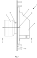
- a hinge 1 consisting of the sash part 2 and a frame part 3 is shown.
- the sash part 2 consists of a rebate rail 4 and a hinge pocket 5 attached to it.
- the rebate rail 5 is fixed in place with fastening screws on the rebate of the sash (not shown).
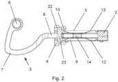
- the frame part 3 has a hinge axis 6 and ends with an angled cantilever arm 7 in a hinge flap 8.
- the hinge flap 8 is designed to be coupled to the sash part 2.
- the hinge pocket 5 has a hinge pocket opening 9 which is open towards the frame fold. The width of the hinge pocket opening 9 in the upper part is adapted to the dimensions of the hinge flap.
- the clamp is U-shaped and symmetrical with respect to a horizontal insertion direction E.
- the hinge pocket 5 forms a housing for the hinge flap 8 and the clamping parts and adjustment pieces arranged therein, as will be shown below.
- the strap pocket 5 is equipped with a clamp 10 in the lower section.
- the clamp 10 is in the embodiment according to Fig. 2 U-shaped and rests on a lower horizontal wall 11.
- the clamp 10 is formed from a leaf spring strip and has an arc-shaped course in the middle region in which the two legs 12, 13 of the clamp 10 approach each other.
- a diverter 14 is located between the legs 12, 13 of the clamp 10.
- the diverter 14 is designed as a flat strip in one plane.
- the thickness of the flat strip is less in this direction than the thickness of the band flap 8.
- the diverter 14 is provided with three reinforcements 15, 16 and 17.
- the reinforcement 16 is arranged in such a way that it is between the smallest distance between the two mutually facing arches of the Clamp 10, while the reinforcements 15 and 17 are located near the ends of the diverter 14.
- the reinforcements 15, 16, 17 are designed symmetrically with respect to a longitudinal center axis of the diverter 14 and their dimensions widen the diverter 14 to a size that is slightly larger than the thickness of the band flap 8.
- This design gives the diverter 14 a first flat rectangular shape and, in the plane running transversely thereto, the flat rectangular contour with two elongated constrictions between the reinforcements 15, 16, 17.
- the diverter 14 can be swiveled by means of a tool engagement (not shown here).
- the function of the hinge is determined from the arrangement as follows: The wing to which the hinge pocket 5 is attached is guided in the insertion direction E towards the frame part 3. The wing part 2 is pulled over the hinge flap 8. The hinge flap 8 thereby penetrates into the hinge pocket opening 9. In order to be able to pass the retaining projection 18 of the adjustment piece 19 protruding into the hinge pocket opening 9, the wing is raised so far that the hinge flap 8 is guided along the lower wall 11. The hinge flap 8 pivots the legs 12, 13 outwards.
- the retaining projection 18 moves into the retaining recess 20 of the hinge flap 8.
- the legs 12, 13 spring back again and the long edges of the legs 12, 13 grip in the area of the arches facing each other under the hinge flap 8 that has been moved upwards.
- the legs 12, 13 bounce off the diverter 14 and produce an audible clicking noise, which signals to the user that the lifting lock has been activated.
- the legs 12, 13 are supported on the lower wall 11.
- the retaining projection 18 can therefore no longer emerge from the retaining recess 20 of the hinge flap 8.
- the clamp 10 forms a clamping part 21. The sash is thus secured against being lifted out.
- the diverter 14 can be pivoted by 90°.
- the diverter 14 with the reinforcement 16 spreads the clamp 10 and is held in this position by the clamp 10.
- the hinge flap 8 can now pass unhindered between the pivoted back legs when the sash is lifted.
- the Fig. 2 The embodiment shown shows a U-shaped clamp 10.
- the clamp 10 can also be equipped with only one leg, which is initially swung out to the side by the hinge flap during assembly and swings back into its clamping position when the sash is lifted as a result of the elastic restoring force.
- the folding rail 4 forms a recess 22 which is open in the direction of the fold and into which the hinge pocket 5 is seated with a flange 23.
- the folding rail 4 thus forms a stationary bearing for the hinge pocket 5, which enables adjustment of the hinge pocket 5 relative to the folding rail 4 via adjusting means such as eccentric pins.
Landscapes
- Engineering & Computer Science (AREA)
- Mechanical Engineering (AREA)
- Hinges (AREA)
- Specific Sealing Or Ventilating Devices For Doors And Windows (AREA)
Abstract
Description
- Gegenstand der Erfindung ist ein Band für eine Tür oder ein Fenster nach dem Obergriff des Anspruchs 1.
- Ein solches Band ist aus der
EP 3529440 B1 bereits bekannt. Das Band besteht aus einem Rahmenteil und einem Flügelteil. Das Flügelteil und das Rahmenteil werden getrennt voneinander an Flügel und Rahmen montiert. Das Rahmenteil besteht aus einem Befestigungsabschnitt und einem daran gelenkig gelagerten Kupplungsstück. Das Kupplungsstück weist einen Bandlappen auf, der flach rechteckig als Zunge mit konisch zulaufendem Ende und zwei sich an parallelen Seitenkanten gegenüberliegenden randoffenen Halteausnehmungen. An dem Flügel sind Bandtaschen in Ausnehmungen befestigt. Um den Flügel am Rahmen zu befestigten werden die zusammen mit dem Flügel beweglichen Bandtaschen über die Bandlappen gestülpt und der Flügel anschließend abgesenkt. Dadurch greift ein im Flügelteil angeordneter Haltevorsprung in die obere Halteausnehmung des Bandlappens ein. Der Haltevorsprung ist über eine Stellvorrichtung horizontal verschiebbar, so dass der Bandlappen relativ zu der Bandtasche justiert werden kann. Solange der Flügel durch sein Gewicht die Bandtasche mit dem Haltevorsprung in die Halteausnehmung presst, ist der Flügel gesichert. Um zu verhindern, dass der Haltevorsprung aus der Halteausnehmung herausrückt, ist eine Aushebesicherung vorgesehen. - Bei der offenkundigen Vorbenutzung SIEGENIA- Axxent von 06/2011 wird eine Bandaufnahme PFVP7000 verwendet. Die Aushebesicherung hier besteht aus einem frontseitig an dem unteren Ende der Bandtasche angebrachten Abdeckblech, welches mit einem Abschnitt in die Öffnung der Bandtasche vorragt und diese teilweise verschließt. Dadurch kann der Bandlappen beim Anheben des Flügels an das Abdeckblech anstoßen, was ein weiteres Anheben verhindert. Das Abdeckblech muss manuell angebracht werden.
- Daher sieht die
EP 3529440 B1 ein Klemmteil vor, welches in Einschubrichtung des Bandlappens entgegen einer Federkraft beweglich in der Bandtasche gelagert ist. Wird der Flügel mit Bandtaschen über die Bandlappen geschoben, dann drückt der Bandlappen das Klemmteil in der Tasche nach hinten in die Bandtasche. Wird der Flügel abgesenkt, dann gibt der Bandlappen das Klemmteil frei, welches infolge der Federkraft in Richtung des Falzes gedrückt wird. Das Klemmteil untergreift dann mit einem schlüsselbartartigen Vorsprung den Bandlappen. Damit ist das Bewegungsspiel des Bandlappens in der Bandtasche begrenzt. Das Klemmteil muss dazu in der Bandtasche in einer Führung beweglich geführt sein. Daher hat das Klemmteil die Querschnittsform eines Schlüssels mit Bart. Der zylindrische Abschnitt bildet die Führung des Klemmteils und auf diesen wirkt die Druckfeder, die ebenfalls in der Führung untergebracht werden muss. - Die Ausgestaltung besteht daher zumindest aus der Feder und dem Klemmteil. Das bewegliche Klemmteil muss in der Führung montiert werden und erfordert zusätzlichen Raum hinter der Bandtasche. Da die Führung und das Klemmteil am unteren Ende der Bandtasche angebracht sind, können Verschmutzungen und Abrieb die Beweglichkeit des Klemmteils beeinträchtigen. Zudem stellt die Ausgestaltung einen erheblichen Aufwand bei der Montage da und besitzt den Nachteil., dass das Klemmteil in der vorbeschriebenen Ausführungsform den Bandlappen auf einer geringen Teillänge abstützt. Um dies zu verhindern, sieht die
EP 3529440 B1 zusätzliche Mittel vor, beispielsweise in Fig. 4 und Fig. 7. - Aus der
DE 20 2017 005 348 U1 ist ein Band entsprechend der offenkundigen Vorbenutzung SIEGENIA-Axxent bekannt geworden, bei dem eine zusätzliche Verstelleinrichtung vorgeschlagen wird. - Der Erfindung liegt die Aufgabe zugrunde, die Nachteile des Standes der Technik zu vermeiden und eine einfache leicht zu montierende Aushebesicherung bereitzustellen, die ohne manuellen Eingriff aktiviert wird und aus wenigen Bauteilen besteht.
- Zur Lösung sieht die Erfindung vor, dass das Klemmteil eine Klammer ist, die beim Einführen des Bandlappens von diesem gespreizt wird und eine Vertikalverschiebung des Bandlappens ermöglicht, bis der Bandlappen mit dem Haltevorsprung zusammenwirkt und die Klammer den Bandlappen mit dem Stützabschnitt untergreift.
- Durch diese Ausgestaltung muss nur die Feder in der Bandtasche vorgesehen werden, die beim Einschieben des Bandlappens seitlich durch eine horizontale Bewegung ausweicht und keinen Bauraum im Rückraum der Bandtasche beansprucht. Im einfachsten Fall sieht die Erfindung daher eine Feder mit nur einem Schenkel vor, der bei Einschieben durch seitliches Ausweichen und elastische Verformung beim Einschieben des Bandlappens ausweicht und beim Absenken des Flügels in den freiwerdenden Raum zurückfedert.
- Eine Weiterbildung sieht vor, dass die Klammer U-förmig ist. Dadurch wird eine größere Stabilität erreicht, wobei die grundsätzliche Funktion erhalten bleibt.
- Für die letztgenannte Ausgestaltung ist es vorteilhaft, wenn die beiden Schenkel in der Sicherungsstellung horizontal in die Entspannungslage zurückkehren, um den Bandlappen sicher untergreifen zu können.
- Eine einfache und zugleich stabile Ausgestaltung wird erreicht, wenn die Feder aus einem Blattfederstreifen gebildet ist, der hochkant in der Bandtasche angeordnet ist.
- Damit der Bandlappen zuverlässig abgestützt ist, wird vorgesehen, dass die Feder in einem Mittleren Abschnitt einen zur Bandtaschenmitte weisenden Bogen aufweist.
- Um eine Deaktivierung der Aushebesicherung, z.B. im Falle einer Demontage, erreichen zu können reicht das Einführen eines entsprechenden Werkzeugs in den Bereich der Feder. Es wird aber mit Vorteil vorgeschlagen, dass in der Bandtasche ein Umsteller angeordnet ist, der das Klemmteil bedarfsweise in eine Freigabestellung auslenkt.
- In den Zeichnungen werden weitere vorteilhafte Ausgestaltungen dargestellt. Es zeigt:
-
Fig. 1 eine Gesamtansicht eines Bandes bestehend aus einem Flügelbandteil und einem Rahmenbandteil, -
Fig. 2 eine Schnittdarstellung des Bandes entlang der Linie II-II inFig. 1 , -
Fig. 3 eine Gesamtdarstellung des montierten Bandes mit teilweise geöffneter Bandtasche. - In der
Fig. 1 ist ein Band 1 bestehend aus dem Flügelteil 2 und einem Rahmenteil 3 dargestellt. Das Flügelteil 2 besteht aus einer Falzschiene 4 und einer daran befestigten Bandtasche 5. Die Falzschiene 5 ist mit Befestigungsschrauben ortsfest am Falz des nicht dargestellten Flügels festgelegt. - Aus der
Fig. 2 ist ersichtlich, dass das Rahmenteil 3 eine Scharnierachse 6 aufweist und mit einem abgewinkelten Kragarm 7 in einem Bandlappen 8 endet. Der Bandlappen 8 ist zur Kopplung mit dem Flügelteil 2 ausgelegt. Die Bandtasche 5 weist dazu eine Bandtaschenöffnung 9 auf, die zum Rahmenfalz hin offen ist. Die Bandtaschenöffnung 9 ist in ihrer Breite im oberen Teil an die Abmessung des Bandlappens angepasst. Im Ausführungsbeispiel ist die Klammer U-förmig und symmetrisch bezogen auf einer horizontale Einschubrichtung E. Die Bandtasche 5 bildet ein Gehäuse für den Bandlappen 8 und darin angeordnete Klemmteile und Verstellstücke, wie nachstehend noch gezeigt werden wird. - Wie die
Fig. 3 zeigt, ist die Bandtasche 5 im unteren Abschnitt mit einer Klammer 10 ausgestattet. Die Klammer 10 ist im Ausführungsbeispiel nachFig. 2 U-förmig und stützt sich auf einer unteren horizontalen Wand 11 ab. Ausweislich derFig. 2 ist die Klammer 10 aus einem Blattfederstreifen geformt und weist in dem mittleren Bereich einen bogenförmigen Verlauf auf, in dem sich die beiden Schenkeln 12, 13 der Klammer 10 annähern. - Zwischen den Schenkeln 12, 13 der Klammer 10 liegt ein Umsteller 14. Der Umsteller 14 ist in einer Ebene als Flachstreifen ausgebildet. Die Stärke des Flachstreifens ist in dieser Richtung geringer bemessen als die Stärke des Bandlappens 8. In der Ebene quer dazu ist der Umsteller 14 mit drei Verstärkungen 15, 16 und 17 versehen. Die Verstärkung 16 ist so angeordnet, dass sie zwischen dem geringsten Abstand der beiden aufeinander zuweisenden Bögen der Klammer 10 liegt, während die Verstärkungen 15 und 17 nahe der Enden des Umstellers 14 liegen. Die Verstärkungen 15, 16, 17 sind bezogen auf eine Längsmittelachse des Umstellers 14 symmetrisch ausgebildet und ihre Abmessungen verbreitern den Umsteller 14 auf ein Maß, dass geringfügig größer bemessen ist als die Stärke des Bandlappens 8. Der Umsteller 14 erhält durch diese Ausgestaltung eine erste flachrechteckige Form und in der quer dazu verlaufenden Ebene die flachrechteckige Kontur mit zwei länglichen Einschnürungen zwischen den Verstärkungen 15, 16, 17. Der Umsteller 14 ist durch einen hier nicht dargestellten Werkzeugeingriff umschwenkbar.
- Die Funktionsweise des Bandes ergibt sich aus der Anordnung wie folgt: Der Flügel, an dem die Bandtasche 5 befestigt ist, wird in Einschubrichtung E an das Rahmenteil 3 herangeführt. Das Flügelteil 2 wird über den Bandlappen 8 gestülpt. Der Bandlappen 8 dringt dadurch in die Bandtaschenöffnung 9 ein. Um den in die Bandtaschenöffnung 9 vorragenden Haltevorsprung 18 des Verstellstücks 19 passieren zu können wird der Flügel soweit angehoben, dass der Bandlappen 8 entlang der unteren Wand 11 geführt wird. Dabei schwenkt der Bandlappen 8 die Schenkel 12, 13 nach außen.
- Wird der Flügel abgesenkt, rückt der Haltevorsprung 18 in die Halteausnehmung 20 des Bandlappens 8 ein. Die Schenkel 12, 13 federn wieder zurück und die Längskanten der Schenkel 12, 13 greifen im Bereich der aufeinander zuweisenden Bögen unter den nach oben verlagerten Bandlappen 8. Dabei prallen die Schenkel 12, 13 an den Umsteller 14 und erzeugen ein vernehmliches Klackgeräusch, welches dem Nutzer die aktivierte Aushebesperre signalisiert. Die Schenkel 12, 13 stützen sich an der unteren Wand 11 ab. Der Haltevorsprung 18 kann dadurch nicht mehr aus der Halteausnehmung 20 des Bandlappens 8 heraustreten. Die Klammer 10 bildet ein Klemmteil 21. Der Flügel ist dadurch gegen ein Ausheben gesichert.
- Um den Flügel wieder demontieren zu können, kann der Umsteller 14 um 90° geschwenkt werden. Dabei spreizt der Umsteller 14 mit der Verstärkung 16 die Klammer 10 und wird in dieser Haltung durch die Klammer 10 gehalten. Der Bandlappen 8 kann nun ungehindert zwischen die zurückgeschwenkten Schenkel treten, wenn der Flügel angehoben wird.
- Das in den
Fig. 2 dargestellte Ausführungsbeispiel zeigt eine U-förmige Klammer 10. Abweichend davon kann die Klammer 10 auch mit nur einem Schenkel ausgestattet sein, der von dem Bandlappen bei der Montage zunächst seitlich ausgeschwenkt wird und durch das Anheben des Flügels infolge der elastischen Rückstellkraft in seine Klemmstellung zurückschwenkt. - Wie aus der
Fig. 2 noch hervorgeht, bildet die Falzschiene 4 eine in Richtung des Falzes offene Mulde 22 aus, in welche die Bandtasche 5 mit einem Flansch 23 einsitzt. Die Falzschiene 4 bildet dadurch ein ortsfestes Lager für die Bandtasche 5 die über Stellmittel wie Exzenterzapfen eine Justage der Bandtasche 5 relativ zu der Falzschiene 4 ermöglicht. -
- 1
- Band
- 2
- Flügelteil
- 3
- Rahmenteil
- 4
- Falzschiene
- 5
- Bandtasche
- 6
- Scharnierachse
- 7
- Kragarm
- 8
- Bandlappen
- 9
- Bandtaschenöffnung
- 10
- Klammer
- 11
- Wand
- 12
- Schenkel
- 13
- Schenkel
- 14
- Umsteller
- 15
- Verstärkung
- 16
- Verstärkung
- 17
- Verstärkung
- 18
- Haltevorsprung
- 19
- Verstellstück
- 20
- Halteausnehmung
- 21
- Klemmteil
- 22
- Mulde
- 23
- Flansch
Claims (6)
- Band (1) für eine Tür oder ein Fenster,welches ein Rahmenteil (3) und ein Flügelteil (2) umfasst,die jeweils im Rahmen bzw. im Flügel der Tür oder des Fensters anordnenbar sind, wobei der Rahmenteil (3) einen Befestigungsabschnitt aufweist, der über eine Scharnierachse (6) mit einem sich im Wesentlichen normal zum Falz in eine Bandtaschenöffnung (9) in einem Gehäuse des Flügelteils (2) erstreckenden Bandlappen (8) verbunden ist,und wobei die Eindringtiefe des Bandlappens (8) im Flügelteil (2) einem Mehrfachen seiner Dicke in Richtung normal zur Flügelebene der Tür bzw. des Fensters entspricht, wobei zur Lagefixierung des Bandlappens (8) im Flügelteil (2) ein Klemmteil (21) vorgesehen ist,das Klemmteil (21) ist innerhalb der Bandtaschenöffnung (9) für den Bandlappen (8) angeordnet,das Klemmteil (21) stützt den Bandlappen (8) gegen das Flügelteil (2) ab,das Klemmteil (21) beim Einführen des Bandlappens (8) mit dem Bandlappen (8) zusammenwirkt,nach vollständigem Einschieben des Bandlappens (8) und Absenken des Flügelteils (2) greift ein im Flügelteil (2) angeordneter Haltevorsprung (18) in einer Halteausnehmung (20) des Bandlappens (8) ein, dadurch gekennzeichnet,dass das Klemmteil (21) eine Klammer (10) ist, die beim Einführen des Bandlappens (8) von diesem ausgelenkt wird und eine Vertikalverschiebung des Bandlappens (8) ermöglicht, bis der Bandlappen (8) mit dem Haltevorsprung (18) zusammenwirkt und die Klammer (10) den Bandlappen (8) untergreift.
- Band nach Anspruch 1, dadurch gekennzeichnet,
dass die Klammer (10) U-förmig ist. - Band nach Anspruch 2, dadurch gekennzeichnet,
dass die beiden Schenkel (12, 13) in der Sicherungsstellung horizontal in die Entspannungslage zurückkehren. - Band nach einem der Ansprüche 1 bis 3, dadurch gekennzeichnet, dass die Klammer (10) aus einem Blattfederstreifen gebildet ist, der hochkant in der Bandtaschenöffnung (9) angeordnet ist.
- Band nach einem der Ansprüche 1 bis 4, dadurch gekennzeichnet, dass die Schenkel (12, 13) in einem mittleren Abschnitt einen zur Bandtaschenmitte weisenden Bogen aufweist.
- Band nach einem der Ansprüche 1 bis 5, dadurch gekennzeichnet, dass in der Bandtasche (8) ein Umsteller (14) angeordnet ist, der das Klemmteil (21) bedarfsweise in eine Freigabestellung auslenkt.
Applications Claiming Priority (1)
| Application Number | Priority Date | Filing Date | Title |
|---|---|---|---|
| DE202023102012.7U DE202023102012U1 (de) | 2023-04-19 | 2023-04-19 | Band für eine Tür oder ein Fenster |
Publications (2)
| Publication Number | Publication Date |
|---|---|
| EP4450742A1 true EP4450742A1 (de) | 2024-10-23 |
| EP4450742B1 EP4450742B1 (de) | 2025-12-31 |
Family
ID=86499056
Family Applications (1)
| Application Number | Title | Priority Date | Filing Date |
|---|---|---|---|
| EP24169219.3A Active EP4450742B1 (de) | 2023-04-19 | 2024-04-09 | Band für eine tür oder ein fenster |
Country Status (2)
| Country | Link |
|---|---|
| EP (1) | EP4450742B1 (de) |
| DE (1) | DE202023102012U1 (de) |
Citations (4)
| Publication number | Priority date | Publication date | Assignee | Title |
|---|---|---|---|---|
| US20090089974A1 (en) * | 2006-04-05 | 2009-04-09 | Bror Fries | Height adjustment device for a hinge |
| AT14782U1 (de) * | 2014-12-19 | 2016-06-15 | Roto Frank Ag | Band für eine Tür oder ein Fenster |
| DE202017005348U1 (de) | 2017-10-13 | 2017-11-10 | Siegenia-Aubi Kg | Drehbeschlag für die verdeckte Anordnung an Fenster oder Türen |
| WO2018073327A1 (de) * | 2016-10-19 | 2018-04-26 | Roto Frank Ag | Band für eine tür oder ein fenster |
-
2023
- 2023-04-19 DE DE202023102012.7U patent/DE202023102012U1/de active Active
-
2024
- 2024-04-09 EP EP24169219.3A patent/EP4450742B1/de active Active
Patent Citations (5)
| Publication number | Priority date | Publication date | Assignee | Title |
|---|---|---|---|---|
| US20090089974A1 (en) * | 2006-04-05 | 2009-04-09 | Bror Fries | Height adjustment device for a hinge |
| AT14782U1 (de) * | 2014-12-19 | 2016-06-15 | Roto Frank Ag | Band für eine Tür oder ein Fenster |
| WO2018073327A1 (de) * | 2016-10-19 | 2018-04-26 | Roto Frank Ag | Band für eine tür oder ein fenster |
| EP3529440B1 (de) | 2016-10-19 | 2020-08-05 | Roto Frank Fenster- und Türtechnologie GmbH | Band für eine tür oder ein fenster |
| DE202017005348U1 (de) | 2017-10-13 | 2017-11-10 | Siegenia-Aubi Kg | Drehbeschlag für die verdeckte Anordnung an Fenster oder Türen |
Also Published As
| Publication number | Publication date |
|---|---|
| EP4450742B1 (de) | 2025-12-31 |
| DE202023102012U1 (de) | 2023-05-08 |
Similar Documents
| Publication | Publication Date | Title |
|---|---|---|
| DE3001260C2 (de) | Flügelrahmen mit Treibstangenbeschlag | |
| DE2262341A1 (de) | Oberkantenhalterung fuer einen schwenkkippfluegel eines fensters, einer tuer od. dgl | |
| DE3619682C2 (de) | ||
| EP4450742B1 (de) | Band für eine tür oder ein fenster | |
| DE3004854C2 (de) | Feststellvorrichtung für Flügel von Fenstern, Türen o.dgl. in wenigstens einer Spaltlüftungsstellung | |
| DE1810671A1 (de) | Stelleinrichtung an Fenstern,Tueren od.dgl. | |
| DE7634928U1 (de) | Oberkantenhalterung für einen kippbaren Flügel eines Fensters, einer Tür o.dgl | |
| DE102005056151B4 (de) | Ecklageranordnung für Fenster, Türen oder dergleichen | |
| DE10056607C1 (de) | Fehlbedienungssperre für Treibstangenbeschläge | |
| EP1614844A2 (de) | Drehlagervorrichtung | |
| DE7520486U (de) | Ausstellvorrichtung für aus Metalloder Kunststoffprofilen zusammengesetzte Fenster und Türen o.dgl | |
| EP0246431A2 (de) | Ausstellvorrichtung für Kippflügel, insbesondere Drehkipp- oder auch Schiebekippflügel, von Fenstern, Türen od. dgl. | |
| DE659001C (de) | Beschlag, insbesondere fuer Fluegelfenster | |
| DE4133343C1 (en) | Door hinge for furniture - has arm end with joint connection bent or angled to bring hinge arm in parallel to arm long axis | |
| DE2202433A1 (de) | Schnappvorrichtung | |
| DE2937889C2 (de) | ||
| EP2573304B1 (de) | Beschlag zur leichten Einstellung einer Sperrkraft | |
| DE2020240C3 (de) | Verschluss für einen Schwenk-Kippflügel eines Fensters, einer Tür o.dgl. | |
| DE973610C (de) | Mit einem Scharnier vereinigte Hebevorrichtung fuer Tuer- oder Fensterfluegel od. dgl. | |
| DE1459209A1 (de) | Beschlag fuer wahlweise um eine lotrechte seitliche Achse schwenkbare oder um eine waagerechte untere Achse kippbare Fluegel von Fenstern,Tueren od. dgl. | |
| DE202025101377U1 (de) | Band für eine Tür oder ein Fenster | |
| DE102022131675A1 (de) | Schließvorrichtung | |
| DE202005009745U1 (de) | Beschlaganordnung | |
| DE8624314U1 (de) | Ausstellvorrichtung für den wenigstens drehbaren Flügel eines Fensters, einer Tür od.dgl. | |
| EP3205803B1 (de) | Vorrichtung zur dämpfung und begrenzung einer öffnungsbewegung |
Legal Events
| Date | Code | Title | Description |
|---|---|---|---|
| PUAI | Public reference made under article 153(3) epc to a published international application that has entered the european phase |
Free format text: ORIGINAL CODE: 0009012 |
|
| STAA | Information on the status of an ep patent application or granted ep patent |
Free format text: STATUS: THE APPLICATION HAS BEEN PUBLISHED |
|
| AK | Designated contracting states |
Kind code of ref document: A1 Designated state(s): AL AT BE BG CH CY CZ DE DK EE ES FI FR GB GR HR HU IE IS IT LI LT LU LV MC ME MK MT NL NO PL PT RO RS SE SI SK SM TR |
|
| STAA | Information on the status of an ep patent application or granted ep patent |
Free format text: STATUS: REQUEST FOR EXAMINATION WAS MADE |
|
| 17P | Request for examination filed |
Effective date: 20250318 |
|
| RIC1 | Information provided on ipc code assigned before grant |
Ipc: E05D 7/12 20060101AFI20250804BHEP |
|
| GRAP | Despatch of communication of intention to grant a patent |
Free format text: ORIGINAL CODE: EPIDOSNIGR1 |
|
| STAA | Information on the status of an ep patent application or granted ep patent |
Free format text: STATUS: GRANT OF PATENT IS INTENDED |
|
| INTG | Intention to grant announced |
Effective date: 20250916 |
|
| GRAS | Grant fee paid |
Free format text: ORIGINAL CODE: EPIDOSNIGR3 |
|
| GRAA | (expected) grant |
Free format text: ORIGINAL CODE: 0009210 |
|
| STAA | Information on the status of an ep patent application or granted ep patent |
Free format text: STATUS: THE PATENT HAS BEEN GRANTED |
|
| AK | Designated contracting states |
Kind code of ref document: B1 Designated state(s): AL AT BE BG CH CY CZ DE DK EE ES FI FR GB GR HR HU IE IS IT LI LT LU LV MC ME MK MT NL NO PL PT RO RS SE SI SK SM TR |
|
| REG | Reference to a national code |
Ref country code: CH Ref legal event code: F10 Free format text: ST27 STATUS EVENT CODE: U-0-0-F10-F00 (AS PROVIDED BY THE NATIONAL OFFICE) Effective date: 20251231 Ref country code: GB Ref legal event code: FG4D Free format text: NOT ENGLISH |
|
| REG | Reference to a national code |
Ref country code: DE Ref legal event code: R096 Ref document number: 502024000569 Country of ref document: DE |
|
| REG | Reference to a national code |
Ref country code: IE Ref legal event code: FG4D Free format text: LANGUAGE OF EP DOCUMENT: GERMAN |
|
| REG | Reference to a national code |
Ref country code: LT Ref legal event code: MG9D |
|
| PG25 | Lapsed in a contracting state [announced via postgrant information from national office to epo] |
Ref country code: NO Free format text: LAPSE BECAUSE OF FAILURE TO SUBMIT A TRANSLATION OF THE DESCRIPTION OR TO PAY THE FEE WITHIN THE PRESCRIBED TIME-LIMIT Effective date: 20260331 |
|
| PG25 | Lapsed in a contracting state [announced via postgrant information from national office to epo] |
Ref country code: HR Free format text: LAPSE BECAUSE OF FAILURE TO SUBMIT A TRANSLATION OF THE DESCRIPTION OR TO PAY THE FEE WITHIN THE PRESCRIBED TIME-LIMIT Effective date: 20251231 Ref country code: FI Free format text: LAPSE BECAUSE OF FAILURE TO SUBMIT A TRANSLATION OF THE DESCRIPTION OR TO PAY THE FEE WITHIN THE PRESCRIBED TIME-LIMIT Effective date: 20251231 |
|
| REG | Reference to a national code |
Ref country code: NL Ref legal event code: FP |
|
| PG25 | Lapsed in a contracting state [announced via postgrant information from national office to epo] |
Ref country code: RS Free format text: LAPSE BECAUSE OF FAILURE TO SUBMIT A TRANSLATION OF THE DESCRIPTION OR TO PAY THE FEE WITHIN THE PRESCRIBED TIME-LIMIT Effective date: 20260331 |
|
| PG25 | Lapsed in a contracting state [announced via postgrant information from national office to epo] |
Ref country code: LV Free format text: LAPSE BECAUSE OF FAILURE TO SUBMIT A TRANSLATION OF THE DESCRIPTION OR TO PAY THE FEE WITHIN THE PRESCRIBED TIME-LIMIT Effective date: 20251231 |