EP4450030A2 - Implantat mit gekrümmten knochenkontaktelementen - Google Patents
Implantat mit gekrümmten knochenkontaktelementen Download PDFInfo
- Publication number
- EP4450030A2 EP4450030A2 EP24198492.1A EP24198492A EP4450030A2 EP 4450030 A2 EP4450030 A2 EP 4450030A2 EP 24198492 A EP24198492 A EP 24198492A EP 4450030 A2 EP4450030 A2 EP 4450030A2
- Authority
- EP
- European Patent Office
- Prior art keywords
- implant
- bone contacting
- arched
- contacting element
- arched bone
- Prior art date
- Legal status (The legal status is an assumption and is not a legal conclusion. Google has not performed a legal analysis and makes no representation as to the accuracy of the status listed.)
- Pending
Links
- 239000007943 implant Substances 0.000 title claims abstract description 459
- 210000000988 bone and bone Anatomy 0.000 title claims abstract description 273
- 230000002093 peripheral effect Effects 0.000 claims abstract description 75
- 230000008468 bone growth Effects 0.000 claims description 23
- 238000003780 insertion Methods 0.000 description 54
- 230000037431 insertion Effects 0.000 description 54
- 210000002414 leg Anatomy 0.000 description 53
- 238000000034 method Methods 0.000 description 38
- 238000002513 implantation Methods 0.000 description 37
- 239000000463 material Substances 0.000 description 27
- 230000004927 fusion Effects 0.000 description 15
- 230000001737 promoting effect Effects 0.000 description 12
- 210000003131 sacroiliac joint Anatomy 0.000 description 11
- 230000006641 stabilisation Effects 0.000 description 6
- 238000011105 stabilization Methods 0.000 description 6
- 108010007726 Bone Morphogenetic Proteins Proteins 0.000 description 4
- 102000007350 Bone Morphogenetic Proteins Human genes 0.000 description 4
- RTAQQCXQSZGOHL-UHFFFAOYSA-N Titanium Chemical compound [Ti] RTAQQCXQSZGOHL-UHFFFAOYSA-N 0.000 description 4
- 229940112869 bone morphogenetic protein Drugs 0.000 description 4
- 238000007373 indentation Methods 0.000 description 4
- 230000001788 irregular Effects 0.000 description 4
- 239000011148 porous material Substances 0.000 description 4
- 210000002303 tibia Anatomy 0.000 description 4
- 239000010936 titanium Substances 0.000 description 4
- 229910052719 titanium Inorganic materials 0.000 description 4
- 238000010146 3D printing Methods 0.000 description 3
- 238000002955 isolation Methods 0.000 description 3
- 238000004519 manufacturing process Methods 0.000 description 3
- 229910052751 metal Inorganic materials 0.000 description 3
- 239000002184 metal Substances 0.000 description 3
- 210000000130 stem cell Anatomy 0.000 description 3
- 239000000126 substance Substances 0.000 description 3
- VTYYLEPIZMXCLO-UHFFFAOYSA-L Calcium carbonate Chemical compound [Ca+2].[O-]C([O-])=O VTYYLEPIZMXCLO-UHFFFAOYSA-L 0.000 description 2
- 102000008186 Collagen Human genes 0.000 description 2
- 108010035532 Collagen Proteins 0.000 description 2
- 102000018233 Fibroblast Growth Factor Human genes 0.000 description 2
- 108050007372 Fibroblast Growth Factor Proteins 0.000 description 2
- 102000010780 Platelet-Derived Growth Factor Human genes 0.000 description 2
- 108010038512 Platelet-Derived Growth Factor Proteins 0.000 description 2
- 239000004696 Poly ether ether ketone Substances 0.000 description 2
- 239000011324 bead Substances 0.000 description 2
- 210000000459 calcaneus Anatomy 0.000 description 2
- OSGAYBCDTDRGGQ-UHFFFAOYSA-L calcium sulfate Chemical compound [Ca+2].[O-]S([O-])(=O)=O OSGAYBCDTDRGGQ-UHFFFAOYSA-L 0.000 description 2
- 210000000038 chest Anatomy 0.000 description 2
- 239000011248 coating agent Substances 0.000 description 2
- 238000000576 coating method Methods 0.000 description 2
- 229920001436 collagen Polymers 0.000 description 2
- 230000006835 compression Effects 0.000 description 2
- 238000007906 compression Methods 0.000 description 2
- 229940126864 fibroblast growth factor Drugs 0.000 description 2
- 210000002683 foot Anatomy 0.000 description 2
- 210000003692 ilium Anatomy 0.000 description 2
- 238000001746 injection moulding Methods 0.000 description 2
- 210000003127 knee Anatomy 0.000 description 2
- 210000000113 medial cuneiform Anatomy 0.000 description 2
- 150000002739 metals Chemical class 0.000 description 2
- 229920002530 polyetherether ketone Polymers 0.000 description 2
- 102000004169 proteins and genes Human genes 0.000 description 2
- 108090000623 proteins and genes Proteins 0.000 description 2
- 239000007787 solid Substances 0.000 description 2
- 238000001356 surgical procedure Methods 0.000 description 2
- 229920002994 synthetic fiber Polymers 0.000 description 2
- QORWJWZARLRLPR-UHFFFAOYSA-H tricalcium bis(phosphate) Chemical compound [Ca+2].[Ca+2].[Ca+2].[O-]P([O-])([O-])=O.[O-]P([O-])([O-])=O QORWJWZARLRLPR-UHFFFAOYSA-H 0.000 description 2
- 229910000951 Aluminide Inorganic materials 0.000 description 1
- IYMAXBFPHPZYIK-BQBZGAKWSA-N Arg-Gly-Asp Chemical class NC(N)=NCCC[C@H](N)C(=O)NCC(=O)N[C@@H](CC(O)=O)C(O)=O IYMAXBFPHPZYIK-BQBZGAKWSA-N 0.000 description 1
- 208000010392 Bone Fractures Diseases 0.000 description 1
- 108010049931 Bone Morphogenetic Protein 2 Proteins 0.000 description 1
- 108010049955 Bone Morphogenetic Protein 4 Proteins 0.000 description 1
- 108010049974 Bone Morphogenetic Protein 6 Proteins 0.000 description 1
- 108010049870 Bone Morphogenetic Protein 7 Proteins 0.000 description 1
- 102100028728 Bone morphogenetic protein 1 Human genes 0.000 description 1
- 108090000654 Bone morphogenetic protein 1 Proteins 0.000 description 1
- 102100024506 Bone morphogenetic protein 2 Human genes 0.000 description 1
- 102100024505 Bone morphogenetic protein 4 Human genes 0.000 description 1
- 102100022525 Bone morphogenetic protein 6 Human genes 0.000 description 1
- 102100022544 Bone morphogenetic protein 7 Human genes 0.000 description 1
- OYPRJOBELJOOCE-UHFFFAOYSA-N Calcium Chemical compound [Ca] OYPRJOBELJOOCE-UHFFFAOYSA-N 0.000 description 1
- 229910000684 Cobalt-chrome Inorganic materials 0.000 description 1
- 206010010356 Congenital anomaly Diseases 0.000 description 1
- 206010017076 Fracture Diseases 0.000 description 1
- 208000007366 Genu Valgum Diseases 0.000 description 1
- 208000010300 Genu Varum Diseases 0.000 description 1
- 206010061246 Intervertebral disc degeneration Diseases 0.000 description 1
- 206010062061 Knee deformity Diseases 0.000 description 1
- 206010028980 Neoplasm Diseases 0.000 description 1
- 208000007103 Spondylolisthesis Diseases 0.000 description 1
- 229910001069 Ti alloy Inorganic materials 0.000 description 1
- 239000002253 acid Substances 0.000 description 1
- 108010072041 arginyl-glycyl-aspartic acid Proteins 0.000 description 1
- 238000000429 assembly Methods 0.000 description 1
- 230000000712 assembly Effects 0.000 description 1
- 239000011230 binding agent Substances 0.000 description 1
- 239000000560 biocompatible material Substances 0.000 description 1
- 229920000249 biocompatible polymer Polymers 0.000 description 1
- 238000005422 blasting Methods 0.000 description 1
- 210000002805 bone matrix Anatomy 0.000 description 1
- 239000011575 calcium Substances 0.000 description 1
- 229910052791 calcium Inorganic materials 0.000 description 1
- 229910000019 calcium carbonate Inorganic materials 0.000 description 1
- 239000001506 calcium phosphate Substances 0.000 description 1
- 235000011010 calcium phosphates Nutrition 0.000 description 1
- 210000004027 cell Anatomy 0.000 description 1
- 239000000919 ceramic Substances 0.000 description 1
- 239000010952 cobalt-chrome Substances 0.000 description 1
- 238000000748 compression moulding Methods 0.000 description 1
- 210000000460 cuneiform bone Anatomy 0.000 description 1
- 208000018180 degenerative disc disease Diseases 0.000 description 1
- 230000001419 dependent effect Effects 0.000 description 1
- 238000003618 dip coating Methods 0.000 description 1
- 201000010099 disease Diseases 0.000 description 1
- 208000037265 diseases, disorders, signs and symptoms Diseases 0.000 description 1
- 238000005530 etching Methods 0.000 description 1
- 239000003102 growth factor Substances 0.000 description 1
- 229940088597 hormone Drugs 0.000 description 1
- 239000005556 hormone Substances 0.000 description 1
- 229910052588 hydroxylapatite Inorganic materials 0.000 description 1
- 238000003384 imaging method Methods 0.000 description 1
- 208000015181 infectious disease Diseases 0.000 description 1
- 208000014674 injury Diseases 0.000 description 1
- 208000021600 intervertebral disc degenerative disease Diseases 0.000 description 1
- 230000036244 malformation Effects 0.000 description 1
- 239000003550 marker Substances 0.000 description 1
- 239000011159 matrix material Substances 0.000 description 1
- 210000002901 mesenchymal stem cell Anatomy 0.000 description 1
- 238000003801 milling Methods 0.000 description 1
- 238000012986 modification Methods 0.000 description 1
- 230000004048 modification Effects 0.000 description 1
- 230000000921 morphogenic effect Effects 0.000 description 1
- 238000000465 moulding Methods 0.000 description 1
- 201000008482 osteoarthritis Diseases 0.000 description 1
- 210000000963 osteoblast Anatomy 0.000 description 1
- 230000004820 osteoconduction Effects 0.000 description 1
- XYJRXVWERLGGKC-UHFFFAOYSA-D pentacalcium;hydroxide;triphosphate Chemical compound [OH-].[Ca+2].[Ca+2].[Ca+2].[Ca+2].[Ca+2].[O-]P([O-])([O-])=O.[O-]P([O-])([O-])=O.[O-]P([O-])([O-])=O XYJRXVWERLGGKC-UHFFFAOYSA-D 0.000 description 1
- 238000002360 preparation method Methods 0.000 description 1
- 238000007639 printing Methods 0.000 description 1
- 102000004196 processed proteins & peptides Human genes 0.000 description 1
- 108090000765 processed proteins & peptides Proteins 0.000 description 1
- 230000001681 protective effect Effects 0.000 description 1
- 206010039722 scoliosis Diseases 0.000 description 1
- 238000000926 separation method Methods 0.000 description 1
- 238000004904 shortening Methods 0.000 description 1
- 238000005245 sintering Methods 0.000 description 1
- 238000009751 slip forming Methods 0.000 description 1
- 208000005198 spinal stenosis Diseases 0.000 description 1
- 239000007921 spray Substances 0.000 description 1
- 238000005507 spraying Methods 0.000 description 1
- 238000004544 sputter deposition Methods 0.000 description 1
- 239000000758 substrate Substances 0.000 description 1
- 230000003746 surface roughness Effects 0.000 description 1
- 229920001059 synthetic polymer Polymers 0.000 description 1
- 238000001721 transfer moulding Methods 0.000 description 1
- 230000008733 trauma Effects 0.000 description 1
- 238000012800 visualization Methods 0.000 description 1
Images


Classifications
-
- A—HUMAN NECESSITIES
- A61—MEDICAL OR VETERINARY SCIENCE; HYGIENE
- A61F—FILTERS IMPLANTABLE INTO BLOOD VESSELS; PROSTHESES; DEVICES PROVIDING PATENCY TO, OR PREVENTING COLLAPSING OF, TUBULAR STRUCTURES OF THE BODY, e.g. STENTS; ORTHOPAEDIC, NURSING OR CONTRACEPTIVE DEVICES; FOMENTATION; TREATMENT OR PROTECTION OF EYES OR EARS; BANDAGES, DRESSINGS OR ABSORBENT PADS; FIRST-AID KITS
- A61F2/00—Filters implantable into blood vessels; Prostheses, i.e. artificial substitutes or replacements for parts of the body; Appliances for connecting them with the body; Devices providing patency to, or preventing collapsing of, tubular structures of the body, e.g. stents
- A61F2/02—Prostheses implantable into the body
- A61F2/30—Joints
- A61F2/44—Joints for the spine, e.g. vertebrae, spinal discs
- A61F2/4455—Joints for the spine, e.g. vertebrae, spinal discs for the fusion of spinal bodies, e.g. intervertebral fusion of adjacent spinal bodies, e.g. fusion cages
-
- A—HUMAN NECESSITIES
- A61—MEDICAL OR VETERINARY SCIENCE; HYGIENE
- A61B—DIAGNOSIS; SURGERY; IDENTIFICATION
- A61B17/00—Surgical instruments, devices or methods
- A61B17/56—Surgical instruments or methods for treatment of bones or joints; Devices specially adapted therefor
- A61B17/58—Surgical instruments or methods for treatment of bones or joints; Devices specially adapted therefor for osteosynthesis, e.g. bone plates, screws or setting implements
- A61B17/68—Internal fixation devices, including fasteners and spinal fixators, even if a part thereof projects from the skin
- A61B17/70—Spinal positioners or stabilisers, e.g. stabilisers comprising fluid filler in an implant
- A61B17/7055—Spinal positioners or stabilisers, e.g. stabilisers comprising fluid filler in an implant connected to sacrum, pelvis or skull
-
- A—HUMAN NECESSITIES
- A61—MEDICAL OR VETERINARY SCIENCE; HYGIENE
- A61B—DIAGNOSIS; SURGERY; IDENTIFICATION
- A61B17/00—Surgical instruments, devices or methods
- A61B17/56—Surgical instruments or methods for treatment of bones or joints; Devices specially adapted therefor
- A61B17/58—Surgical instruments or methods for treatment of bones or joints; Devices specially adapted therefor for osteosynthesis, e.g. bone plates, screws or setting implements
- A61B17/68—Internal fixation devices, including fasteners and spinal fixators, even if a part thereof projects from the skin
- A61B17/80—Cortical plates, i.e. bone plates; Instruments for holding or positioning cortical plates, or for compressing bones attached to cortical plates
- A61B17/8095—Wedge osteotomy devices
-
- A—HUMAN NECESSITIES
- A61—MEDICAL OR VETERINARY SCIENCE; HYGIENE
- A61F—FILTERS IMPLANTABLE INTO BLOOD VESSELS; PROSTHESES; DEVICES PROVIDING PATENCY TO, OR PREVENTING COLLAPSING OF, TUBULAR STRUCTURES OF THE BODY, e.g. STENTS; ORTHOPAEDIC, NURSING OR CONTRACEPTIVE DEVICES; FOMENTATION; TREATMENT OR PROTECTION OF EYES OR EARS; BANDAGES, DRESSINGS OR ABSORBENT PADS; FIRST-AID KITS
- A61F2/00—Filters implantable into blood vessels; Prostheses, i.e. artificial substitutes or replacements for parts of the body; Appliances for connecting them with the body; Devices providing patency to, or preventing collapsing of, tubular structures of the body, e.g. stents
- A61F2/02—Prostheses implantable into the body
- A61F2/30—Joints
- A61F2/30721—Accessories
- A61F2/30734—Modular inserts, sleeves or augments, e.g. placed on proximal part of stem for fixation purposes or wedges for bridging a bone defect
-
- A—HUMAN NECESSITIES
- A61—MEDICAL OR VETERINARY SCIENCE; HYGIENE
- A61F—FILTERS IMPLANTABLE INTO BLOOD VESSELS; PROSTHESES; DEVICES PROVIDING PATENCY TO, OR PREVENTING COLLAPSING OF, TUBULAR STRUCTURES OF THE BODY, e.g. STENTS; ORTHOPAEDIC, NURSING OR CONTRACEPTIVE DEVICES; FOMENTATION; TREATMENT OR PROTECTION OF EYES OR EARS; BANDAGES, DRESSINGS OR ABSORBENT PADS; FIRST-AID KITS
- A61F2/00—Filters implantable into blood vessels; Prostheses, i.e. artificial substitutes or replacements for parts of the body; Appliances for connecting them with the body; Devices providing patency to, or preventing collapsing of, tubular structures of the body, e.g. stents
- A61F2/02—Prostheses implantable into the body
- A61F2/30—Joints
- A61F2/30721—Accessories
- A61F2/30744—End caps, e.g. for closing an endoprosthetic cavity
-
- A—HUMAN NECESSITIES
- A61—MEDICAL OR VETERINARY SCIENCE; HYGIENE
- A61F—FILTERS IMPLANTABLE INTO BLOOD VESSELS; PROSTHESES; DEVICES PROVIDING PATENCY TO, OR PREVENTING COLLAPSING OF, TUBULAR STRUCTURES OF THE BODY, e.g. STENTS; ORTHOPAEDIC, NURSING OR CONTRACEPTIVE DEVICES; FOMENTATION; TREATMENT OR PROTECTION OF EYES OR EARS; BANDAGES, DRESSINGS OR ABSORBENT PADS; FIRST-AID KITS
- A61F2/00—Filters implantable into blood vessels; Prostheses, i.e. artificial substitutes or replacements for parts of the body; Appliances for connecting them with the body; Devices providing patency to, or preventing collapsing of, tubular structures of the body, e.g. stents
- A61F2/02—Prostheses implantable into the body
- A61F2/30—Joints
- A61F2/30767—Special external or bone-contacting surface, e.g. coating for improving bone ingrowth
- A61F2/30771—Special external or bone-contacting surface, e.g. coating for improving bone ingrowth applied in original prostheses, e.g. holes or grooves
-
- A—HUMAN NECESSITIES
- A61—MEDICAL OR VETERINARY SCIENCE; HYGIENE
- A61F—FILTERS IMPLANTABLE INTO BLOOD VESSELS; PROSTHESES; DEVICES PROVIDING PATENCY TO, OR PREVENTING COLLAPSING OF, TUBULAR STRUCTURES OF THE BODY, e.g. STENTS; ORTHOPAEDIC, NURSING OR CONTRACEPTIVE DEVICES; FOMENTATION; TREATMENT OR PROTECTION OF EYES OR EARS; BANDAGES, DRESSINGS OR ABSORBENT PADS; FIRST-AID KITS
- A61F2/00—Filters implantable into blood vessels; Prostheses, i.e. artificial substitutes or replacements for parts of the body; Appliances for connecting them with the body; Devices providing patency to, or preventing collapsing of, tubular structures of the body, e.g. stents
- A61F2/02—Prostheses implantable into the body
- A61F2/30—Joints
- A61F2/30988—Other joints not covered by any of the groups A61F2/32 - A61F2/4425
-
- A—HUMAN NECESSITIES
- A61—MEDICAL OR VETERINARY SCIENCE; HYGIENE
- A61F—FILTERS IMPLANTABLE INTO BLOOD VESSELS; PROSTHESES; DEVICES PROVIDING PATENCY TO, OR PREVENTING COLLAPSING OF, TUBULAR STRUCTURES OF THE BODY, e.g. STENTS; ORTHOPAEDIC, NURSING OR CONTRACEPTIVE DEVICES; FOMENTATION; TREATMENT OR PROTECTION OF EYES OR EARS; BANDAGES, DRESSINGS OR ABSORBENT PADS; FIRST-AID KITS
- A61F2/00—Filters implantable into blood vessels; Prostheses, i.e. artificial substitutes or replacements for parts of the body; Appliances for connecting them with the body; Devices providing patency to, or preventing collapsing of, tubular structures of the body, e.g. stents
- A61F2/02—Prostheses implantable into the body
- A61F2/30—Joints
- A61F2/38—Joints for elbows or knees
- A61F2/389—Tibial components
-
- A—HUMAN NECESSITIES
- A61—MEDICAL OR VETERINARY SCIENCE; HYGIENE
- A61F—FILTERS IMPLANTABLE INTO BLOOD VESSELS; PROSTHESES; DEVICES PROVIDING PATENCY TO, OR PREVENTING COLLAPSING OF, TUBULAR STRUCTURES OF THE BODY, e.g. STENTS; ORTHOPAEDIC, NURSING OR CONTRACEPTIVE DEVICES; FOMENTATION; TREATMENT OR PROTECTION OF EYES OR EARS; BANDAGES, DRESSINGS OR ABSORBENT PADS; FIRST-AID KITS
- A61F2/00—Filters implantable into blood vessels; Prostheses, i.e. artificial substitutes or replacements for parts of the body; Appliances for connecting them with the body; Devices providing patency to, or preventing collapsing of, tubular structures of the body, e.g. stents
- A61F2/02—Prostheses implantable into the body
- A61F2/30—Joints
- A61F2/42—Joints for wrists or ankles; for hands, e.g. fingers; for feet, e.g. toes
- A61F2/4225—Joints for wrists or ankles; for hands, e.g. fingers; for feet, e.g. toes for feet, e.g. toes
-
- A—HUMAN NECESSITIES
- A61—MEDICAL OR VETERINARY SCIENCE; HYGIENE
- A61F—FILTERS IMPLANTABLE INTO BLOOD VESSELS; PROSTHESES; DEVICES PROVIDING PATENCY TO, OR PREVENTING COLLAPSING OF, TUBULAR STRUCTURES OF THE BODY, e.g. STENTS; ORTHOPAEDIC, NURSING OR CONTRACEPTIVE DEVICES; FOMENTATION; TREATMENT OR PROTECTION OF EYES OR EARS; BANDAGES, DRESSINGS OR ABSORBENT PADS; FIRST-AID KITS
- A61F2/00—Filters implantable into blood vessels; Prostheses, i.e. artificial substitutes or replacements for parts of the body; Appliances for connecting them with the body; Devices providing patency to, or preventing collapsing of, tubular structures of the body, e.g. stents
- A61F2/02—Prostheses implantable into the body
- A61F2/30—Joints
- A61F2/44—Joints for the spine, e.g. vertebrae, spinal discs
- A61F2/4455—Joints for the spine, e.g. vertebrae, spinal discs for the fusion of spinal bodies, e.g. intervertebral fusion of adjacent spinal bodies, e.g. fusion cages
- A61F2/4465—Joints for the spine, e.g. vertebrae, spinal discs for the fusion of spinal bodies, e.g. intervertebral fusion of adjacent spinal bodies, e.g. fusion cages having a circular or kidney shaped cross-section substantially perpendicular to the axis of the spine
-
- A—HUMAN NECESSITIES
- A61—MEDICAL OR VETERINARY SCIENCE; HYGIENE
- A61F—FILTERS IMPLANTABLE INTO BLOOD VESSELS; PROSTHESES; DEVICES PROVIDING PATENCY TO, OR PREVENTING COLLAPSING OF, TUBULAR STRUCTURES OF THE BODY, e.g. STENTS; ORTHOPAEDIC, NURSING OR CONTRACEPTIVE DEVICES; FOMENTATION; TREATMENT OR PROTECTION OF EYES OR EARS; BANDAGES, DRESSINGS OR ABSORBENT PADS; FIRST-AID KITS
- A61F2/00—Filters implantable into blood vessels; Prostheses, i.e. artificial substitutes or replacements for parts of the body; Appliances for connecting them with the body; Devices providing patency to, or preventing collapsing of, tubular structures of the body, e.g. stents
- A61F2/02—Prostheses implantable into the body
- A61F2/30—Joints
- A61F2/44—Joints for the spine, e.g. vertebrae, spinal discs
- A61F2/4455—Joints for the spine, e.g. vertebrae, spinal discs for the fusion of spinal bodies, e.g. intervertebral fusion of adjacent spinal bodies, e.g. fusion cages
- A61F2/447—Joints for the spine, e.g. vertebrae, spinal discs for the fusion of spinal bodies, e.g. intervertebral fusion of adjacent spinal bodies, e.g. fusion cages substantially parallelepipedal, e.g. having a rectangular or trapezoidal cross-section
-
- B—PERFORMING OPERATIONS; TRANSPORTING
- B33—ADDITIVE MANUFACTURING TECHNOLOGY
- B33Y—ADDITIVE MANUFACTURING, i.e. MANUFACTURING OF THREE-DIMENSIONAL [3-D] OBJECTS BY ADDITIVE DEPOSITION, ADDITIVE AGGLOMERATION OR ADDITIVE LAYERING, e.g. BY 3-D PRINTING, STEREOLITHOGRAPHY OR SELECTIVE LASER SINTERING
- B33Y80/00—Products made by additive manufacturing
-
- A—HUMAN NECESSITIES
- A61—MEDICAL OR VETERINARY SCIENCE; HYGIENE
- A61F—FILTERS IMPLANTABLE INTO BLOOD VESSELS; PROSTHESES; DEVICES PROVIDING PATENCY TO, OR PREVENTING COLLAPSING OF, TUBULAR STRUCTURES OF THE BODY, e.g. STENTS; ORTHOPAEDIC, NURSING OR CONTRACEPTIVE DEVICES; FOMENTATION; TREATMENT OR PROTECTION OF EYES OR EARS; BANDAGES, DRESSINGS OR ABSORBENT PADS; FIRST-AID KITS
- A61F2/00—Filters implantable into blood vessels; Prostheses, i.e. artificial substitutes or replacements for parts of the body; Appliances for connecting them with the body; Devices providing patency to, or preventing collapsing of, tubular structures of the body, e.g. stents
- A61F2/02—Prostheses implantable into the body
- A61F2/30—Joints
- A61F2002/30001—Additional features of subject-matter classified in A61F2/28, A61F2/30 and subgroups thereof
- A61F2002/30003—Material related properties of the prosthesis or of a coating on the prosthesis
- A61F2002/30004—Material related properties of the prosthesis or of a coating on the prosthesis the prosthesis being made from materials having different values of a given property at different locations within the same prosthesis
- A61F2002/30011—Material related properties of the prosthesis or of a coating on the prosthesis the prosthesis being made from materials having different values of a given property at different locations within the same prosthesis differing in porosity
-
- A—HUMAN NECESSITIES
- A61—MEDICAL OR VETERINARY SCIENCE; HYGIENE
- A61F—FILTERS IMPLANTABLE INTO BLOOD VESSELS; PROSTHESES; DEVICES PROVIDING PATENCY TO, OR PREVENTING COLLAPSING OF, TUBULAR STRUCTURES OF THE BODY, e.g. STENTS; ORTHOPAEDIC, NURSING OR CONTRACEPTIVE DEVICES; FOMENTATION; TREATMENT OR PROTECTION OF EYES OR EARS; BANDAGES, DRESSINGS OR ABSORBENT PADS; FIRST-AID KITS
- A61F2/00—Filters implantable into blood vessels; Prostheses, i.e. artificial substitutes or replacements for parts of the body; Appliances for connecting them with the body; Devices providing patency to, or preventing collapsing of, tubular structures of the body, e.g. stents
- A61F2/02—Prostheses implantable into the body
- A61F2/30—Joints
- A61F2002/30001—Additional features of subject-matter classified in A61F2/28, A61F2/30 and subgroups thereof
- A61F2002/30108—Shapes
- A61F2002/3011—Cross-sections or two-dimensional shapes
- A61F2002/30112—Rounded shapes, e.g. with rounded corners
- A61F2002/30113—Rounded shapes, e.g. with rounded corners circular
- A61F2002/30116—Rounded shapes, e.g. with rounded corners circular partial circles, i.e. circular segments
-
- A—HUMAN NECESSITIES
- A61—MEDICAL OR VETERINARY SCIENCE; HYGIENE
- A61F—FILTERS IMPLANTABLE INTO BLOOD VESSELS; PROSTHESES; DEVICES PROVIDING PATENCY TO, OR PREVENTING COLLAPSING OF, TUBULAR STRUCTURES OF THE BODY, e.g. STENTS; ORTHOPAEDIC, NURSING OR CONTRACEPTIVE DEVICES; FOMENTATION; TREATMENT OR PROTECTION OF EYES OR EARS; BANDAGES, DRESSINGS OR ABSORBENT PADS; FIRST-AID KITS
- A61F2/00—Filters implantable into blood vessels; Prostheses, i.e. artificial substitutes or replacements for parts of the body; Appliances for connecting them with the body; Devices providing patency to, or preventing collapsing of, tubular structures of the body, e.g. stents
- A61F2/02—Prostheses implantable into the body
- A61F2/30—Joints
- A61F2002/30001—Additional features of subject-matter classified in A61F2/28, A61F2/30 and subgroups thereof
- A61F2002/30108—Shapes
- A61F2002/3011—Cross-sections or two-dimensional shapes
- A61F2002/30112—Rounded shapes, e.g. with rounded corners
- A61F2002/30125—Rounded shapes, e.g. with rounded corners elliptical or oval
-
- A—HUMAN NECESSITIES
- A61—MEDICAL OR VETERINARY SCIENCE; HYGIENE
- A61F—FILTERS IMPLANTABLE INTO BLOOD VESSELS; PROSTHESES; DEVICES PROVIDING PATENCY TO, OR PREVENTING COLLAPSING OF, TUBULAR STRUCTURES OF THE BODY, e.g. STENTS; ORTHOPAEDIC, NURSING OR CONTRACEPTIVE DEVICES; FOMENTATION; TREATMENT OR PROTECTION OF EYES OR EARS; BANDAGES, DRESSINGS OR ABSORBENT PADS; FIRST-AID KITS
- A61F2/00—Filters implantable into blood vessels; Prostheses, i.e. artificial substitutes or replacements for parts of the body; Appliances for connecting them with the body; Devices providing patency to, or preventing collapsing of, tubular structures of the body, e.g. stents
- A61F2/02—Prostheses implantable into the body
- A61F2/30—Joints
- A61F2002/30001—Additional features of subject-matter classified in A61F2/28, A61F2/30 and subgroups thereof
- A61F2002/30108—Shapes
- A61F2002/3011—Cross-sections or two-dimensional shapes
- A61F2002/30138—Convex polygonal shapes
- A61F2002/30153—Convex polygonal shapes rectangular
-
- A—HUMAN NECESSITIES
- A61—MEDICAL OR VETERINARY SCIENCE; HYGIENE
- A61F—FILTERS IMPLANTABLE INTO BLOOD VESSELS; PROSTHESES; DEVICES PROVIDING PATENCY TO, OR PREVENTING COLLAPSING OF, TUBULAR STRUCTURES OF THE BODY, e.g. STENTS; ORTHOPAEDIC, NURSING OR CONTRACEPTIVE DEVICES; FOMENTATION; TREATMENT OR PROTECTION OF EYES OR EARS; BANDAGES, DRESSINGS OR ABSORBENT PADS; FIRST-AID KITS
- A61F2/00—Filters implantable into blood vessels; Prostheses, i.e. artificial substitutes or replacements for parts of the body; Appliances for connecting them with the body; Devices providing patency to, or preventing collapsing of, tubular structures of the body, e.g. stents
- A61F2/02—Prostheses implantable into the body
- A61F2/30—Joints
- A61F2002/30001—Additional features of subject-matter classified in A61F2/28, A61F2/30 and subgroups thereof
- A61F2002/30108—Shapes
- A61F2002/3011—Cross-sections or two-dimensional shapes
- A61F2002/30159—Concave polygonal shapes
- A61F2002/30176—V-shaped
-
- A—HUMAN NECESSITIES
- A61—MEDICAL OR VETERINARY SCIENCE; HYGIENE
- A61F—FILTERS IMPLANTABLE INTO BLOOD VESSELS; PROSTHESES; DEVICES PROVIDING PATENCY TO, OR PREVENTING COLLAPSING OF, TUBULAR STRUCTURES OF THE BODY, e.g. STENTS; ORTHOPAEDIC, NURSING OR CONTRACEPTIVE DEVICES; FOMENTATION; TREATMENT OR PROTECTION OF EYES OR EARS; BANDAGES, DRESSINGS OR ABSORBENT PADS; FIRST-AID KITS
- A61F2/00—Filters implantable into blood vessels; Prostheses, i.e. artificial substitutes or replacements for parts of the body; Appliances for connecting them with the body; Devices providing patency to, or preventing collapsing of, tubular structures of the body, e.g. stents
- A61F2/02—Prostheses implantable into the body
- A61F2/30—Joints
- A61F2002/30001—Additional features of subject-matter classified in A61F2/28, A61F2/30 and subgroups thereof
- A61F2002/30108—Shapes
- A61F2002/30199—Three-dimensional shapes
- A61F2002/30289—Three-dimensional shapes helically-coiled
-
- A—HUMAN NECESSITIES
- A61—MEDICAL OR VETERINARY SCIENCE; HYGIENE
- A61F—FILTERS IMPLANTABLE INTO BLOOD VESSELS; PROSTHESES; DEVICES PROVIDING PATENCY TO, OR PREVENTING COLLAPSING OF, TUBULAR STRUCTURES OF THE BODY, e.g. STENTS; ORTHOPAEDIC, NURSING OR CONTRACEPTIVE DEVICES; FOMENTATION; TREATMENT OR PROTECTION OF EYES OR EARS; BANDAGES, DRESSINGS OR ABSORBENT PADS; FIRST-AID KITS
- A61F2/00—Filters implantable into blood vessels; Prostheses, i.e. artificial substitutes or replacements for parts of the body; Appliances for connecting them with the body; Devices providing patency to, or preventing collapsing of, tubular structures of the body, e.g. stents
- A61F2/02—Prostheses implantable into the body
- A61F2/30—Joints
- A61F2002/30001—Additional features of subject-matter classified in A61F2/28, A61F2/30 and subgroups thereof
- A61F2002/30108—Shapes
- A61F2002/30199—Three-dimensional shapes
- A61F2002/30291—Three-dimensional shapes spirally-coiled, i.e. having a 2D spiral cross-section
- A61F2002/30298—Parallelepipedal body made by spirally rolling up a sheet or a strip around itself
-
- A—HUMAN NECESSITIES
- A61—MEDICAL OR VETERINARY SCIENCE; HYGIENE
- A61F—FILTERS IMPLANTABLE INTO BLOOD VESSELS; PROSTHESES; DEVICES PROVIDING PATENCY TO, OR PREVENTING COLLAPSING OF, TUBULAR STRUCTURES OF THE BODY, e.g. STENTS; ORTHOPAEDIC, NURSING OR CONTRACEPTIVE DEVICES; FOMENTATION; TREATMENT OR PROTECTION OF EYES OR EARS; BANDAGES, DRESSINGS OR ABSORBENT PADS; FIRST-AID KITS
- A61F2/00—Filters implantable into blood vessels; Prostheses, i.e. artificial substitutes or replacements for parts of the body; Appliances for connecting them with the body; Devices providing patency to, or preventing collapsing of, tubular structures of the body, e.g. stents
- A61F2/02—Prostheses implantable into the body
- A61F2/30—Joints
- A61F2002/30001—Additional features of subject-matter classified in A61F2/28, A61F2/30 and subgroups thereof
- A61F2002/30316—The prosthesis having different structural features at different locations within the same prosthesis; Connections between prosthetic parts; Special structural features of bone or joint prostheses not otherwise provided for
- A61F2002/30329—Connections or couplings between prosthetic parts, e.g. between modular parts; Connecting elements
- A61F2002/30405—Connections or couplings between prosthetic parts, e.g. between modular parts; Connecting elements made by screwing complementary threads machined on the parts themselves
-
- A—HUMAN NECESSITIES
- A61—MEDICAL OR VETERINARY SCIENCE; HYGIENE
- A61F—FILTERS IMPLANTABLE INTO BLOOD VESSELS; PROSTHESES; DEVICES PROVIDING PATENCY TO, OR PREVENTING COLLAPSING OF, TUBULAR STRUCTURES OF THE BODY, e.g. STENTS; ORTHOPAEDIC, NURSING OR CONTRACEPTIVE DEVICES; FOMENTATION; TREATMENT OR PROTECTION OF EYES OR EARS; BANDAGES, DRESSINGS OR ABSORBENT PADS; FIRST-AID KITS
- A61F2/00—Filters implantable into blood vessels; Prostheses, i.e. artificial substitutes or replacements for parts of the body; Appliances for connecting them with the body; Devices providing patency to, or preventing collapsing of, tubular structures of the body, e.g. stents
- A61F2/02—Prostheses implantable into the body
- A61F2/30—Joints
- A61F2002/30001—Additional features of subject-matter classified in A61F2/28, A61F2/30 and subgroups thereof
- A61F2002/30316—The prosthesis having different structural features at different locations within the same prosthesis; Connections between prosthetic parts; Special structural features of bone or joint prostheses not otherwise provided for
- A61F2002/30535—Special structural features of bone or joint prostheses not otherwise provided for
- A61F2002/30593—Special structural features of bone or joint prostheses not otherwise provided for hollow
-
- A—HUMAN NECESSITIES
- A61—MEDICAL OR VETERINARY SCIENCE; HYGIENE
- A61F—FILTERS IMPLANTABLE INTO BLOOD VESSELS; PROSTHESES; DEVICES PROVIDING PATENCY TO, OR PREVENTING COLLAPSING OF, TUBULAR STRUCTURES OF THE BODY, e.g. STENTS; ORTHOPAEDIC, NURSING OR CONTRACEPTIVE DEVICES; FOMENTATION; TREATMENT OR PROTECTION OF EYES OR EARS; BANDAGES, DRESSINGS OR ABSORBENT PADS; FIRST-AID KITS
- A61F2/00—Filters implantable into blood vessels; Prostheses, i.e. artificial substitutes or replacements for parts of the body; Appliances for connecting them with the body; Devices providing patency to, or preventing collapsing of, tubular structures of the body, e.g. stents
- A61F2/02—Prostheses implantable into the body
- A61F2/30—Joints
- A61F2/30721—Accessories
- A61F2/30734—Modular inserts, sleeves or augments, e.g. placed on proximal part of stem for fixation purposes or wedges for bridging a bone defect
- A61F2002/30736—Augments or augmentation pieces, e.g. wedges or blocks for bridging a bone defect
-
- A—HUMAN NECESSITIES
- A61—MEDICAL OR VETERINARY SCIENCE; HYGIENE
- A61F—FILTERS IMPLANTABLE INTO BLOOD VESSELS; PROSTHESES; DEVICES PROVIDING PATENCY TO, OR PREVENTING COLLAPSING OF, TUBULAR STRUCTURES OF THE BODY, e.g. STENTS; ORTHOPAEDIC, NURSING OR CONTRACEPTIVE DEVICES; FOMENTATION; TREATMENT OR PROTECTION OF EYES OR EARS; BANDAGES, DRESSINGS OR ABSORBENT PADS; FIRST-AID KITS
- A61F2/00—Filters implantable into blood vessels; Prostheses, i.e. artificial substitutes or replacements for parts of the body; Appliances for connecting them with the body; Devices providing patency to, or preventing collapsing of, tubular structures of the body, e.g. stents
- A61F2/02—Prostheses implantable into the body
- A61F2/30—Joints
- A61F2/30767—Special external or bone-contacting surface, e.g. coating for improving bone ingrowth
- A61F2/30771—Special external or bone-contacting surface, e.g. coating for improving bone ingrowth applied in original prostheses, e.g. holes or grooves
- A61F2002/30772—Apertures or holes, e.g. of circular cross section
- A61F2002/30774—Apertures or holes, e.g. of circular cross section internally-threaded
-
- A—HUMAN NECESSITIES
- A61—MEDICAL OR VETERINARY SCIENCE; HYGIENE
- A61F—FILTERS IMPLANTABLE INTO BLOOD VESSELS; PROSTHESES; DEVICES PROVIDING PATENCY TO, OR PREVENTING COLLAPSING OF, TUBULAR STRUCTURES OF THE BODY, e.g. STENTS; ORTHOPAEDIC, NURSING OR CONTRACEPTIVE DEVICES; FOMENTATION; TREATMENT OR PROTECTION OF EYES OR EARS; BANDAGES, DRESSINGS OR ABSORBENT PADS; FIRST-AID KITS
- A61F2/00—Filters implantable into blood vessels; Prostheses, i.e. artificial substitutes or replacements for parts of the body; Appliances for connecting them with the body; Devices providing patency to, or preventing collapsing of, tubular structures of the body, e.g. stents
- A61F2/02—Prostheses implantable into the body
- A61F2/30—Joints
- A61F2/30767—Special external or bone-contacting surface, e.g. coating for improving bone ingrowth
- A61F2/30771—Special external or bone-contacting surface, e.g. coating for improving bone ingrowth applied in original prostheses, e.g. holes or grooves
- A61F2002/30838—Microstructures
-
- A—HUMAN NECESSITIES
- A61—MEDICAL OR VETERINARY SCIENCE; HYGIENE
- A61F—FILTERS IMPLANTABLE INTO BLOOD VESSELS; PROSTHESES; DEVICES PROVIDING PATENCY TO, OR PREVENTING COLLAPSING OF, TUBULAR STRUCTURES OF THE BODY, e.g. STENTS; ORTHOPAEDIC, NURSING OR CONTRACEPTIVE DEVICES; FOMENTATION; TREATMENT OR PROTECTION OF EYES OR EARS; BANDAGES, DRESSINGS OR ABSORBENT PADS; FIRST-AID KITS
- A61F2/00—Filters implantable into blood vessels; Prostheses, i.e. artificial substitutes or replacements for parts of the body; Appliances for connecting them with the body; Devices providing patency to, or preventing collapsing of, tubular structures of the body, e.g. stents
- A61F2/02—Prostheses implantable into the body
- A61F2/30—Joints
- A61F2/30767—Special external or bone-contacting surface, e.g. coating for improving bone ingrowth
- A61F2/30771—Special external or bone-contacting surface, e.g. coating for improving bone ingrowth applied in original prostheses, e.g. holes or grooves
- A61F2002/30878—Special external or bone-contacting surface, e.g. coating for improving bone ingrowth applied in original prostheses, e.g. holes or grooves with non-sharp protrusions, for instance contacting the bone for anchoring, e.g. keels, pegs, pins, posts, shanks, stems, struts
- A61F2002/30889—Arcuate pegs
-
- A—HUMAN NECESSITIES
- A61—MEDICAL OR VETERINARY SCIENCE; HYGIENE
- A61F—FILTERS IMPLANTABLE INTO BLOOD VESSELS; PROSTHESES; DEVICES PROVIDING PATENCY TO, OR PREVENTING COLLAPSING OF, TUBULAR STRUCTURES OF THE BODY, e.g. STENTS; ORTHOPAEDIC, NURSING OR CONTRACEPTIVE DEVICES; FOMENTATION; TREATMENT OR PROTECTION OF EYES OR EARS; BANDAGES, DRESSINGS OR ABSORBENT PADS; FIRST-AID KITS
- A61F2/00—Filters implantable into blood vessels; Prostheses, i.e. artificial substitutes or replacements for parts of the body; Appliances for connecting them with the body; Devices providing patency to, or preventing collapsing of, tubular structures of the body, e.g. stents
- A61F2/02—Prostheses implantable into the body
- A61F2/30—Joints
- A61F2/30767—Special external or bone-contacting surface, e.g. coating for improving bone ingrowth
- A61F2/30771—Special external or bone-contacting surface, e.g. coating for improving bone ingrowth applied in original prostheses, e.g. holes or grooves
- A61F2002/30878—Special external or bone-contacting surface, e.g. coating for improving bone ingrowth applied in original prostheses, e.g. holes or grooves with non-sharp protrusions, for instance contacting the bone for anchoring, e.g. keels, pegs, pins, posts, shanks, stems, struts
- A61F2002/30891—Plurality of protrusions
- A61F2002/30894—Plurality of protrusions inclined obliquely with respect to each other
-
- A—HUMAN NECESSITIES
- A61—MEDICAL OR VETERINARY SCIENCE; HYGIENE
- A61F—FILTERS IMPLANTABLE INTO BLOOD VESSELS; PROSTHESES; DEVICES PROVIDING PATENCY TO, OR PREVENTING COLLAPSING OF, TUBULAR STRUCTURES OF THE BODY, e.g. STENTS; ORTHOPAEDIC, NURSING OR CONTRACEPTIVE DEVICES; FOMENTATION; TREATMENT OR PROTECTION OF EYES OR EARS; BANDAGES, DRESSINGS OR ABSORBENT PADS; FIRST-AID KITS
- A61F2/00—Filters implantable into blood vessels; Prostheses, i.e. artificial substitutes or replacements for parts of the body; Appliances for connecting them with the body; Devices providing patency to, or preventing collapsing of, tubular structures of the body, e.g. stents
- A61F2/02—Prostheses implantable into the body
- A61F2/30—Joints
- A61F2/30767—Special external or bone-contacting surface, e.g. coating for improving bone ingrowth
- A61F2002/3092—Special external or bone-contacting surface, e.g. coating for improving bone ingrowth having an open-celled or open-pored structure
-
- A—HUMAN NECESSITIES
- A61—MEDICAL OR VETERINARY SCIENCE; HYGIENE
- A61F—FILTERS IMPLANTABLE INTO BLOOD VESSELS; PROSTHESES; DEVICES PROVIDING PATENCY TO, OR PREVENTING COLLAPSING OF, TUBULAR STRUCTURES OF THE BODY, e.g. STENTS; ORTHOPAEDIC, NURSING OR CONTRACEPTIVE DEVICES; FOMENTATION; TREATMENT OR PROTECTION OF EYES OR EARS; BANDAGES, DRESSINGS OR ABSORBENT PADS; FIRST-AID KITS
- A61F2/00—Filters implantable into blood vessels; Prostheses, i.e. artificial substitutes or replacements for parts of the body; Appliances for connecting them with the body; Devices providing patency to, or preventing collapsing of, tubular structures of the body, e.g. stents
- A61F2/02—Prostheses implantable into the body
- A61F2/30—Joints
- A61F2/30767—Special external or bone-contacting surface, e.g. coating for improving bone ingrowth
- A61F2002/3093—Special external or bone-contacting surface, e.g. coating for improving bone ingrowth for promoting ingrowth of bone tissue
-
- A—HUMAN NECESSITIES
- A61—MEDICAL OR VETERINARY SCIENCE; HYGIENE
- A61F—FILTERS IMPLANTABLE INTO BLOOD VESSELS; PROSTHESES; DEVICES PROVIDING PATENCY TO, OR PREVENTING COLLAPSING OF, TUBULAR STRUCTURES OF THE BODY, e.g. STENTS; ORTHOPAEDIC, NURSING OR CONTRACEPTIVE DEVICES; FOMENTATION; TREATMENT OR PROTECTION OF EYES OR EARS; BANDAGES, DRESSINGS OR ABSORBENT PADS; FIRST-AID KITS
- A61F2/00—Filters implantable into blood vessels; Prostheses, i.e. artificial substitutes or replacements for parts of the body; Appliances for connecting them with the body; Devices providing patency to, or preventing collapsing of, tubular structures of the body, e.g. stents
- A61F2/02—Prostheses implantable into the body
- A61F2/30—Joints
- A61F2/3094—Designing or manufacturing processes
- A61F2/30942—Designing or manufacturing processes for designing or making customized prostheses, e.g. using templates, CT or NMR scans, finite-element analysis or CAD-CAM techniques
- A61F2002/30957—Designing or manufacturing processes for designing or making customized prostheses, e.g. using templates, CT or NMR scans, finite-element analysis or CAD-CAM techniques using a positive or a negative model, e.g. moulds
-
- A—HUMAN NECESSITIES
- A61—MEDICAL OR VETERINARY SCIENCE; HYGIENE
- A61F—FILTERS IMPLANTABLE INTO BLOOD VESSELS; PROSTHESES; DEVICES PROVIDING PATENCY TO, OR PREVENTING COLLAPSING OF, TUBULAR STRUCTURES OF THE BODY, e.g. STENTS; ORTHOPAEDIC, NURSING OR CONTRACEPTIVE DEVICES; FOMENTATION; TREATMENT OR PROTECTION OF EYES OR EARS; BANDAGES, DRESSINGS OR ABSORBENT PADS; FIRST-AID KITS
- A61F2/00—Filters implantable into blood vessels; Prostheses, i.e. artificial substitutes or replacements for parts of the body; Appliances for connecting them with the body; Devices providing patency to, or preventing collapsing of, tubular structures of the body, e.g. stents
- A61F2/02—Prostheses implantable into the body
- A61F2/30—Joints
- A61F2/3094—Designing or manufacturing processes
- A61F2/30942—Designing or manufacturing processes for designing or making customized prostheses, e.g. using templates, CT or NMR scans, finite-element analysis or CAD-CAM techniques
- A61F2002/30962—Designing or manufacturing processes for designing or making customized prostheses, e.g. using templates, CT or NMR scans, finite-element analysis or CAD-CAM techniques using stereolithography
-
- A—HUMAN NECESSITIES
- A61—MEDICAL OR VETERINARY SCIENCE; HYGIENE
- A61F—FILTERS IMPLANTABLE INTO BLOOD VESSELS; PROSTHESES; DEVICES PROVIDING PATENCY TO, OR PREVENTING COLLAPSING OF, TUBULAR STRUCTURES OF THE BODY, e.g. STENTS; ORTHOPAEDIC, NURSING OR CONTRACEPTIVE DEVICES; FOMENTATION; TREATMENT OR PROTECTION OF EYES OR EARS; BANDAGES, DRESSINGS OR ABSORBENT PADS; FIRST-AID KITS
- A61F2/00—Filters implantable into blood vessels; Prostheses, i.e. artificial substitutes or replacements for parts of the body; Appliances for connecting them with the body; Devices providing patency to, or preventing collapsing of, tubular structures of the body, e.g. stents
- A61F2/02—Prostheses implantable into the body
- A61F2/30—Joints
- A61F2/3094—Designing or manufacturing processes
- A61F2002/30985—Designing or manufacturing processes using three dimensional printing [3DP]
-
- A—HUMAN NECESSITIES
- A61—MEDICAL OR VETERINARY SCIENCE; HYGIENE
- A61F—FILTERS IMPLANTABLE INTO BLOOD VESSELS; PROSTHESES; DEVICES PROVIDING PATENCY TO, OR PREVENTING COLLAPSING OF, TUBULAR STRUCTURES OF THE BODY, e.g. STENTS; ORTHOPAEDIC, NURSING OR CONTRACEPTIVE DEVICES; FOMENTATION; TREATMENT OR PROTECTION OF EYES OR EARS; BANDAGES, DRESSINGS OR ABSORBENT PADS; FIRST-AID KITS
- A61F2/00—Filters implantable into blood vessels; Prostheses, i.e. artificial substitutes or replacements for parts of the body; Appliances for connecting them with the body; Devices providing patency to, or preventing collapsing of, tubular structures of the body, e.g. stents
- A61F2/02—Prostheses implantable into the body
- A61F2/30—Joints
- A61F2/30988—Other joints not covered by any of the groups A61F2/32 - A61F2/4425
- A61F2002/30995—Other joints not covered by any of the groups A61F2/32 - A61F2/4425 for sacro-iliac joints
-
- A—HUMAN NECESSITIES
- A61—MEDICAL OR VETERINARY SCIENCE; HYGIENE
- A61F—FILTERS IMPLANTABLE INTO BLOOD VESSELS; PROSTHESES; DEVICES PROVIDING PATENCY TO, OR PREVENTING COLLAPSING OF, TUBULAR STRUCTURES OF THE BODY, e.g. STENTS; ORTHOPAEDIC, NURSING OR CONTRACEPTIVE DEVICES; FOMENTATION; TREATMENT OR PROTECTION OF EYES OR EARS; BANDAGES, DRESSINGS OR ABSORBENT PADS; FIRST-AID KITS
- A61F2310/00—Prostheses classified in A61F2/28 or A61F2/30 - A61F2/44 being constructed from or coated with a particular material
- A61F2310/00005—The prosthesis being constructed from a particular material
- A61F2310/00011—Metals or alloys
- A61F2310/00023—Titanium or titanium-based alloys, e.g. Ti-Ni alloys
-
- B—PERFORMING OPERATIONS; TRANSPORTING
- B22—CASTING; POWDER METALLURGY
- B22F—WORKING METALLIC POWDER; MANUFACTURE OF ARTICLES FROM METALLIC POWDER; MAKING METALLIC POWDER; APPARATUS OR DEVICES SPECIALLY ADAPTED FOR METALLIC POWDER
- B22F10/00—Additive manufacturing of workpieces or articles from metallic powder
- B22F10/20—Direct sintering or melting
-
- B—PERFORMING OPERATIONS; TRANSPORTING
- B22—CASTING; POWDER METALLURGY
- B22F—WORKING METALLIC POWDER; MANUFACTURE OF ARTICLES FROM METALLIC POWDER; MAKING METALLIC POWDER; APPARATUS OR DEVICES SPECIALLY ADAPTED FOR METALLIC POWDER
- B22F3/00—Manufacture of workpieces or articles from metallic powder characterised by the manner of compacting or sintering; Apparatus specially adapted therefor ; Presses and furnaces
- B22F3/10—Sintering only
- B22F3/11—Making porous workpieces or articles
-
- B—PERFORMING OPERATIONS; TRANSPORTING
- B22—CASTING; POWDER METALLURGY
- B22F—WORKING METALLIC POWDER; MANUFACTURE OF ARTICLES FROM METALLIC POWDER; MAKING METALLIC POWDER; APPARATUS OR DEVICES SPECIALLY ADAPTED FOR METALLIC POWDER
- B22F3/00—Manufacture of workpieces or articles from metallic powder characterised by the manner of compacting or sintering; Apparatus specially adapted therefor ; Presses and furnaces
- B22F3/22—Manufacture of workpieces or articles from metallic powder characterised by the manner of compacting or sintering; Apparatus specially adapted therefor ; Presses and furnaces for producing castings from a slip
- B22F3/225—Manufacture of workpieces or articles from metallic powder characterised by the manner of compacting or sintering; Apparatus specially adapted therefor ; Presses and furnaces for producing castings from a slip by injection molding
-
- B—PERFORMING OPERATIONS; TRANSPORTING
- B22—CASTING; POWDER METALLURGY
- B22F—WORKING METALLIC POWDER; MANUFACTURE OF ARTICLES FROM METALLIC POWDER; MAKING METALLIC POWDER; APPARATUS OR DEVICES SPECIALLY ADAPTED FOR METALLIC POWDER
- B22F3/00—Manufacture of workpieces or articles from metallic powder characterised by the manner of compacting or sintering; Apparatus specially adapted therefor ; Presses and furnaces
- B22F3/22—Manufacture of workpieces or articles from metallic powder characterised by the manner of compacting or sintering; Apparatus specially adapted therefor ; Presses and furnaces for producing castings from a slip
- B22F3/227—Manufacture of workpieces or articles from metallic powder characterised by the manner of compacting or sintering; Apparatus specially adapted therefor ; Presses and furnaces for producing castings from a slip by organic binder assisted extrusion
-
- Y—GENERAL TAGGING OF NEW TECHNOLOGICAL DEVELOPMENTS; GENERAL TAGGING OF CROSS-SECTIONAL TECHNOLOGIES SPANNING OVER SEVERAL SECTIONS OF THE IPC; TECHNICAL SUBJECTS COVERED BY FORMER USPC CROSS-REFERENCE ART COLLECTIONS [XRACs] AND DIGESTS
- Y02—TECHNOLOGIES OR APPLICATIONS FOR MITIGATION OR ADAPTATION AGAINST CLIMATE CHANGE
- Y02P—CLIMATE CHANGE MITIGATION TECHNOLOGIES IN THE PRODUCTION OR PROCESSING OF GOODS
- Y02P10/00—Technologies related to metal processing
- Y02P10/25—Process efficiency
Definitions
- the embodiments are generally directed to implants for supporting bone growth in a patient.
- Implants used in the body to stabilize an area and promote bone ingrowth provide both stability (i.e. minimal deformation under pressure over time) and space for bone ingrowth.
- Spinal fusion also known as spondylodesis or spondylosyndesis, is a surgical treatment method used for the treatment of various morbidities such as degenerative disc disease, spondylolisthesis (slippage of a vertebra), spinal stenosis, scoliosis, fracture, infection or tumor.
- the aim of the spinal fusion procedure is to reduce instability and thus pain.
- the spinal fusion cage In preparation for the spinal fusion, most of the intervertebral disc is removed.
- An implant, the spinal fusion cage may be placed between the vertebra to maintain spine alignment and disc height.
- the fusion i.e. bone bridge, occurs between the endplates of the vertebrae.
- Wedge implants may also be used in other parts of the body to fuse adjacent bones other than vertebrae, or to fuse segments of a single bone such as for an opening wedge osteotomy.
- wedge implants may also be used for osteotomy procedures, as well as sacroiliac (S.I.) joint fusion or stabilization procedures.
- an implant in one aspect, includes a body, a first arched bone contacting element having two ends attached to the body; and a second arched bone contacting element having two ends attached to the body.
- an implant in another aspect, includes a body including a lateral axis.
- the implant also includes a first arched bone contacting element oriented at a first angle with respect to the lateral axis and a second arched bone contacting element oriented at a second angle with respect to the lateral axis. The first angle is different from the second angle.
- an implant in another aspect, includes a body comprising a peripheral structure, a first support beam and a second support beam.
- the peripheral structure bounds an interior region and the first support beam and the second support beam span the interior region.
- the implant also includes a first arched bone contacting element extending from a portion of the peripheral structure to the first support beam and a second arched bone contacting element extending from the first support beam to the second support beam.
- an implant in another aspect, includes a body having a leading edge portion, a trailing edge portion, and an intermediate portion extending between the leading edge portion and the trailing edge portion.
- the leading edge portion includes a substantially smooth surface forming a substantial majority of a leading edge surface of the leading edge portion.
- the trailing edge portion includes a monolithic structure including at least one receptacle configured to receive an insertion tool.
- the intermediate portion includes a plurality of elongate curved structural members.
- an implant in another aspect, includes a body having a leading edge portion, a trailing edge portion, and an intermediate portion extending between the leading edge portion and the trailing edge portion.
- the leading edge portion includes a substantially smooth surface forming a substantial majority of a leading edge surface of the leading edge portion.
- the trailing edge portion includes a monolithic structure including at least one receptacle configured to receive an insertion tool.
- the implant further includes at least one elongate substantially spiral member forming perimeter portions of the implant extending between the leading edge portion and the trailing edge portion.
- an implant in another aspect, includes a body having a leading edge portion, a trailing edge portion, and an intermediate portion extending between the leading edge portion and the trailing edge portion.
- the leading edge portion includes a substantially smooth surface forming a substantial majority of a leading edge surface of the leading edge portion.
- the trailing edge portion includes a monolithic structure including at least one receptacle configured to receive an insertion tool.
- the implant includes at least one support beam extending between the leading edge portion and the trailing edge portion.
- the implant includes at least one elongate substantially helical member extending between the leading edge portion and the trailing edge portion.
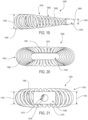
- the embodiments described herein are directed to implants including portions for insertion within recesses in bone.
- the portions configured for insertion within the recesses each include a body having a substrate or central portion and a multi-layer bone interfacing lattice.
- the layers of the bone interfacing lattice may include elongate curved structural members.
- Such structural members may have any of a variety of curved configurations.
- the structural members may include portions that are helical, spiraled, coiled, sinusoidal, arched, or otherwise curved. Examples of such curved configurations are provided in the following applications.
- any of the embodiments disclosed herein may make use of any of the body/support structures, frames, plates, coils or other structures disclosed in McShane III et al., Protected Fusion Zones," and which is incorporated herein by reference in its entirety.
- this application will be referred to throughout the present application as "The Protective Fusion Zones application.” (Currently U.S. Patent Application No. 15/334,022, filed on October 25, 2016 ; Attorney Docket No. 138-1007.)
- any of the embodiments disclosed herein may make use of any of the body/support structures, elements, frames, plates or other structures disclosed in McShane III et al., U.S. Publication Number 2017/0042697, published on February 16, 2017 , and titled “Implant with Arched Bone Contacting Elements,” and which is incorporated herein by reference in its entirety. (Attorney Docket No. 138-1009.)
- any of the embodiments disclosed herein may make use of any of the body/support structures, elements, frames, plates or other structures disclosed in McShane III et al., U.S. Publication Number _, published on _, and titled “Implant with Structural Members Arranged Around a Ring,” and which is incorporated herein by reference in its entirety and referred to herein as "The Ring application.”
- the Ring application currently U.S. Patent Application No. 15/457,470, filed on March 13, 2017 ; Attorney Docket No. 138-1012.
- any of the embodiments disclosed herein may make use of any of the body/support structures, elements, frames, plates, or other structures disclosed in Morris et al., U.S. Publication Number 2016/0324656, published on November 10, 2016 , and titled “Coiled Implants and Systems and Methods of Use Thereof,” and which is incorporated herein by reference in its entirety and referred to herein as "The Coiled Implant Application.” (Attorney Docket No. 138-1024.)
- any of the embodiments disclosed herein may make use of any of the body/support structures, elements, frames, plates, or other structures disclosed in Nyahay et al., U.S. Publication Number ______, published on ______, and entitled “Implant with Bone Contacting Elements Having Helical and Undulating Planar Geometries,” and which is incorporated herein by reference in its entirety.
- any of the embodiments disclosed herein may make use of any of the body/support structures, elements, frames, plates, or other structures disclosed in Nyahay et al., U.S. Publication Number ___, published on ___, and entitled “Corpectomy Implant,” and which is incorporated herein by reference in its entirety.
- any of the embodiments disclosed herein may make use of any of the body/support structures, elements, frames, plates, or other structures disclosed in Bishop et al., U.S. Publication Number ___, published on ___, and entitled “Implant with Supported Helical Members,” and which is incorporated herein by reference in its entirety.
- any of the embodiments disclosed herein may make use of any of the body/support structures, elements, frames, plates, or other structures disclosed in ___ et al., U.S. Publication Number ___, published on ___, and entitled “________,” and which is incorporated herein by reference in its entirety. (Currently U.S. Patent Application No. ___, filed on ____; Attorney Docket No. 138-1046.)
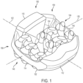
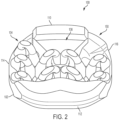
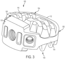
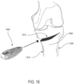
- FIGS. 1-3 illustrate isometric views of an embodiment of implant 100.
- Implant 100 may also be referred to as a cage or fusion device.
- implant 100 is configured to be implanted within a portion of the human body.
- implant 100 may be configured for implantation into the spine.
- implant 100 may be a spinal fusion implant, or spinal fusion device, that is inserted between adjacent vertebrae to provide support and/or facilitate fusion between the vertebrae.
- implant 100 may include a body 102.
- Body 102 may generally provide a frame or skeleton for implant 100.
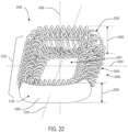
- implant 100 may also include a plurality of arched bone contacting elements 104. Plurality of arched bone contacting elements 104 may be attached, and/or continuously formed (or "integrally formed") with, body 102.
- each arched bone contacting element comprises a distinctive member or element that spans a region or area of an implant.
- these elements may overlap or intersect, similar to elements in a lattice or other 3D mesh structure. In other embodiments, the elements may not overlap or intersect.
- Some embodiments may use elements in which the length of the element is greater than its width and its thickness. For example, in embodiments where an element has an approximately circular cross-sectional shape, the element has a length greater than its diameter. In the embodiments seen in FIGS. 1-3 , each arched bone contacting element is seen to have an approximately rounded or circular cross-sectional shape (i.e., the element has the geometry of a solid tube) along at least a portion of the element.
- an element could have any other cross-sectional shape, including, but not limited to various polygonal cross-sectional shapes, as well as any other regular and/or irregular cross-sectional shapes.
- the cross-sectional shape of an arched bone contacting element could vary along its length (e.g., the diameter or shape could change along its length).
- anterior refers to a side or portion of an implant that is intended to be oriented towards the front of the human body when the implant has been placed in the body.
- posterior refers to a side or portion of an implant that is intended to be oriented towards the back of the human body following implantation.
- superior refers to a side or portion of an implant that is intended to be oriented towards a top (e.g., the head) of the body while “inferior” refers to a side or portion of an implant that is intended to be oriented towards a bottom of the body.
- lateral sides or portions of an implant, which are sides or portions facing along lateral directions of the body following implantation.
- implant 100 is understood to be configured with an anterior side 110 and a posterior side 112.
- Implant 100 may also include a first lateral side 114 and a second lateral side 116 that extend between the posterior side 112 and the anterior side 110 on opposing sides of implant 100.
- implant 100 may also include a superior side 130 and an inferior side 140.
- distal refers to a part that is located further from a center of an implant
- proximal refers to a part that is located closer to the center of the implant.
- center of the implant could be the center of mass and/or a central plane and/or another centrally located reference surface.
- fixedly attached shall refer to two components joined in a manner such that the components may not be readily separated (for example, without destroying one or both components).
- implant 100 may be associated with a lateral axis 120 that extends along implant 100 between first lateral side 114 and second lateral side 116. Additionally, implant 100 may be associated with a posterior-anterior axis 122 that extends between posterior side 112 and anterior side 110. Moreover, implant 100 may be associated with a vertical axis 124 that extends along the thickness dimension of implant 100 and which is generally perpendicular to both lateral axis 120 and posterior-anterior axis 122.
- An implant may also be associated with various reference planes or surfaces.
- the term “median plane” refers to a vertical plane which passes from the anterior side to the posterior side of the implant, dividing the implant into right and left halves, or lateral halves.
- the term “transverse plane” refers to a horizontal plane located in the center of the implant that divides the implant into superior and inferior halves.
- the term “coronal plane” refers to a vertical plane located in the center of the implant that divides the implant into anterior and posterior halves.
- the implant is symmetric about two planes, such as the transverse plane.
- a body may comprise a peripheral structure and one or more support beams that extend from the peripheral structure.
- a peripheral structure may be comprised of any number of plates, walls or similar structures.
- the peripheral structure could comprise a ring.
- the peripheral structure could be a peripheral ring structure.
- body 102 may be further comprised of a peripheral structure 150. Peripheral structure 150 is seen to have a ring-like geometry.
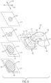
- FIG. 4 is a schematic isometric view of body 102 shown in isolation without any arched bone contacting elements
- FIG. 5 is a schematic top view of body 102 in isolation from any arched bone contacting elements.
- peripheral structure 150 may be further comprised of an anterior side 152, a posterior side 154, a first lateral side 156 and a second lateral side 158.
- peripheral structure 150 is a continuous structure so that anterior side 152 is connected to first lateral side 156, first lateral side 156 is connected to posterior side 154, posterior side 154 is connected to second lateral side 158 and second lateral side 158 is connected to anterior side 152. That is, anterior side 152, first lateral side 156, posterior side 154 and second lateral side 158 together form a continuous or unbroken ring.
- FIG. 6 is a schematic front view of implant 100 while FIG. 7 is a schematic rear view of implant 100.
- anterior side 152 is further comprised of a first anterior portion 160 and a second anterior portion 162.
- First lateral side 156 extends from first anterior portion 160 of anterior side 152 to posterior side 154.
- second lateral side 158 extends from second anterior portion 162 of anterior side 152 to posterior side 154.
- First anterior portion 160 is comprised of a distal surface 164 (best seen in FIG. 6 ), a superior surface 166 and an inferior surface 168. First anterior portion 160 also includes a first lateral surface 170 and a second lateral surface (not shown) opposite first lateral surface 170. In addition, first anterior portion 160 includes a proximal surface 174 that is joined with a second support beam 254 as discussed below.
- Second anterior portion 162 includes distal surface 184 (best seen in FIG. 6 ), a superior surface 186 and an inferior surface (not shown). Second anterior portion 162 also includes a first lateral surface 190 (see FIG. 5 ). In addition, second anterior portion 162 includes a proximal surface 194 that is joined with a third support beam 256 as discussed below. Moreover, second anterior portion 162 is disposed adjacent to first anterior portion 160. In some embodiments, first anterior portion 160 and second anterior portion 162 are joined together.
- first lateral side 156 and second lateral side 158 comprise a distal surface joined with a proximal surface.
- the proximal surface may be convex.
- first lateral side 156 includes distal surface 210 and proximal surface 212, where proximal surface 212 is convex and joined directly to distal surface 210 along the superior and inferior sides of implant 100.
- Posterior side 154 of implant 100 comprises a superior surface 200 and an inferior surface 202 (see FIG. 7 ).
- Posterior side 154 also includes a distal surface 204 and a proximal surface 206. As seen in FIG. 5 , the geometry of implant 100 at posterior side 154 tapers towards first lateral side 156 and second lateral side 158.
- first anterior portion 160 is shown to have a first height 300 while second anterior portion 162 is shown to have a second height 302.
- first height 300 is seen to be greater than second height 302.
- this tapering in height from the centrally located first anterior portion 160 to the adjacent second anterior portion 162 helps give anterior side 152 of peripheral structure 150 a convex shape to better fit between adjacent vertebral bodies upon implantation.
- third height 304 is less than first height 300.
- third height 304 may be slightly less than second height 302.
- variations in height or vertical thickness between the posterior and anterior sides of an implant may allow for an implant with hyper-lordotic angles between the inferior and superior surfaces.
- variations in vertical thickness may be used to control the relative rigidity of the device in different locations.
- the thickness of peripheral structure 150 may be smaller along both of first lateral side 156 and second lateral side 158 than along either of anterior side 152 or posterior side 154.
- first lateral side 156 and second lateral side 158 have a similar fourth height 306.
- fourth height 306 is less than first height 300, second height 302 and third height 304.
- a body may be provided with one or more support beams (or support structures) that act to reinforce a peripheral structure.
- one or more support beams could be disposed along the interior of a peripheral structure.
- one or more support beams could extend from a first location on an inwardly (or proximally) facing surface of the support structure to a second location on the inwardly facing surface of the support structure.
- one or more support beams may span an interior region bounded by the peripheral structure.
- body 102 includes a plurality of support beams 250. These include first support beam 252, second support beam 254 and third support beam 256. In the embodiment shown in FIGS. 4-5 , each of these support beams extends from a first location on inwardly facing surface 260 of peripheral structure 150 to a second location on an inwardly facing surface of peripheral structure 150.
- the inwardly facing surface 260 of peripheral structure 150 is comprised of the proximal surfaces of the various sides of peripheral structure 150 (e.g., proximal surface 174, proximal surface 194, proximal surface 212, etc.).
- first support beam 252 includes a first end 270 attached to a first anterior location 271 of inwardly facing surface 260 and a second end 272 attached at a second anterior location 273 of inwardly facing surface 260.
- each of second support beam 254 and third support beam 256 include opposing ends attached to different locations along inwardly facing surface 260.
- plurality of support beams 250 are seen to span an interior region 290 (or central region) that is bounded by peripheral structure 150.
- the plurality of support beams 250 may be characterized as being centrally located within implant 100 with respect to peripheral structure 150.
- centrally located does not refer to a precise location that is at the geometric center or center of mass of an implant, but rather a general area or region disposed inwardly of a peripheral structure (e.g., within interior region 290).
- a support beam may be referred to as a central beam.
- the number of support beams could vary. In some embodiments, a single support beam could be used. In other embodiments, two or more support beams could be used. In the exemplary embodiment shown in FIGS. 4-5 , three support beams are used.
- the orientation of one or more beams could vary.
- two or more support beams could be oriented in parallel.
- two or more support beams could be disposed at oblique angles to one another.
- first support beam 252, second support beam 254 and third support beam 256 may be disposed in parallel to one another.
- plurality of support beams 250 may be oriented in a posterior-anterior direction (i.e., along posterior-anterior axis 122).
- plurality of support beams 250 could be oriented in any other directions.
- the spacing, or separation, between adjacent support beams could vary.
- the spacing between adjacent support beams could be small relative to the lateral width of an implant.
- the spacing could range between 0% and 10% of the width of an implant.
- the spacing between adjacent support beams could be large relative to the width of an implant.
- the spacing could range between 10% and 95% of the width of an implant (for example, two beams located adjacent to opposing lateral sides of the implant may could be spaced apart by 95% of the width of the implant).
- the spacing between adjacent beams (or between a beam and a portion of a peripheral structure) may be constant or may vary across an implant.
- the relative spacing between support beams may be selected according to many factors, including the thicknesses of one or more support beams, the number of support beams used, the desired strength to weight ratio for an implant as well as other factors. Moreover, the spacing between adjacent support beams may be determined according to the dimensions of one or more arched bone contacting elements, since the arched bone contacting elements extend between adjacent support beams (or between a support beam and the peripheral structure).
- first support beam 252 is spaced apart from first lateral side 156 by a spacing 292.
- First support beam 252 and second support beam 254 are spaced apart from one another by a spacing 294.
- Second support beam 254 and third support beam 256 are spaced apart from one another by a spacing 296.
- Third support beam 256 is spaced apart from second lateral side 158 by spacing 298.
- each of spacing 292, spacing 294, spacing 296 and spacing 298 generally have a value in the range between 15% and 30% of width 199 of implant 100.
- each spacing is an average or approximate spacing, since the spacing between adjacent components can vary, for example, along posterior-anterior axis 122.
- the geometry of one or more support beams could vary. In some embodiments, one or more support beams could have a curved geometry. In other embodiments, one or more support beams could have a substantially straight geometry. In the embodiment shown in FIGS. 4-5 , each of plurality of support beams 250 has a substantially straight geometry. Moreover, the cross-sectional geometry of each support beam is substantially rounded. However, in other embodiments, one or more support beams could have any other cross-sectional shape, including but not limited to: rectangular shapes, polygonal shapes, regular shapes and/or irregular shapes.
- cross-sectional shapes could also vary across a length of a support beam from, for example, a rounded cross-sectional shape (e.g., circular or elliptic) to a polygonal cross-sectional shape (e.g., rectangular).
- a rounded cross-sectional shape e.g., circular or elliptic
- a polygonal cross-sectional shape e.g., rectangular
- the thickness of one or more support beams could vary.
- the thickness (or diameter) of a support beam could vary in a range between 1 % and 95% of the width (or length) of an implant.
- first support beam 252, second support beam 254 and third support beam 256 have diameters in a range approximately between 2% and 15% of width 199 of implant 100, as seen in FIG. 4 .
- second support beam 254 has a diameter 255 that is greater than a diameter 253 of first support beam 252 and also that is greater than a diameter 257 of third support beam 256.
- second support beam 254 may have the largest diameter. Because impact forces are applied at the center of implant 100 (where second support beam 254 is located) by a device coupled to implant 100 at first interior portion 160, this greater diameter for second support beam 254 may help reinforce the center of implant 100.
- support beams in the body of an implant may be coplanar.
- first support beam 252, second support beam 254 and third support beam 256 are seen to reside in a similar plane of implant 100.
- the coplanar arrangement of support beams may help provide a generally symmetric arrangement for implant 100 between the superior and inferior sides.
- portions of a body of an implant could vary from one embodiment to another.
- portions of a body can include one or more windows, slots and/or openings that may facilitate bone growth through the implant and/or may reduce weight.
- Some embodiments can include one or more fastener receiving provisions. Some embodiments can include one or more attachment openings that may engage an insertion or implantation device. In some embodiments, an implant can include one or more threaded cavities. In some embodiments, a threaded cavity can be configured to mate with a corresponding threaded tip on an implantation tool or device. In other embodiments, a threaded cavity can receive a fastener for purposes of fastening an implant to another device or component in an implantation system that uses multiple implants and/or multiple components.
- implant 100 includes a first threaded cavity 360 disposed in first anterior portion 160.
- Implant 100 also includes second threaded cavity 362 disposed in second anterior portion 162.
- first threaded cavity 360 may receive the threaded tip of an implantation tool (not shown). Such a tool could be used to drive implant 100 between adjacent vertebral bodies.
- implant 100 may also include a pair of indentations (indentation 365 and indentation 367) that may facilitate alignment between an implantation tool and implant 100.
- second threaded cavity 362 could be used to fasten implant 100 to a separate component (not shown) of a broader implantation system.
- some embodiments could incorporate a separate plate that may be fastened to implant 100 using a fastener secured within first threaded cavity 360 or second threaded cavity 362.
- a plate could include additional fixation members (e.g., screws) that could be used with the implant.
- an arched bone contacting element may include a first end portion, an intermediate portion and a second end portion.
- the intermediate portion may have an arched geometry.
- an intermediate portion having an arched geometry may be referred to as an "arched portion”.
- the first end portion and/or the second end portion could have a flared geometry.
- an end having a flared geometry may be referred to as a "flared leg" of the arched bone contacting element.
- FIG. 8 is a schematic view of an exemplary arched bone contacting element seen in isolation, including several enlarged schematic cross-sectional views taken at various locations of the element.
- arched bone contacting element 400 is comprised of a first end portion, which is referred to as a first flared leg 402.
- Arched bone contacting element 400 is also comprised of an arched portion 404.
- arched bone contacting element 400 is comprised of a second end portion, which is referred to as a second flared leg 406.
- an arched bone contacting element can include provisions for engaging a vertebral body following implantation.
- one or more arched bone contacting elements can include at least one distal surface region that is configured to directly contact a vertebral endplate.
- a distal surface region could be a flattened surface region.
- a distal surface region could be a convex surface region.
- a distal surface region could be a concave surface region. More generally, a distal surface region could have a different curvature from the adjacent surface regions of an arched portion. Moreover, the particular curvature for a distal surface region could be selected to match the local geometry of an opposing vertebral endplate.
- arched bone contacting element 400 is seen to include a distal surface region 490 that is located in arched portion 404.
- distal surface region 490 may have a convex curvature that is smaller than the curvature of adjacent regions of arched portion 404.
- the remaining arched bone contacting elements of implant 100 are also configured with distal bone contacting regions having a smaller curvature than adjacent surface regions of arched portion 404 (i.e., these distal surface regions may be flatter than the remaining regions of arched portion 404, but may not be completely flat). Together, these distal bone contacting regions provide a partial smooth surface that can engage a vertebral body.
- the collection of flattened (or convex) bone contacting regions together form a minimal contact surface with the bone and thereby allow for an increased amount of graft material or bone growth promoting material to be placed in direct contact with the bone.
- bone growth promoting material that is disposed in between arched bone contacting elements, including being disposed in the open regions along the superior and inferior surfaces, may directly contact the bone.
- arched bone contacting element 400 may be characterized as having a curved central axis 401.
- the curved central axis of an element is an axis that extends along the length of the element and is located at an approximate center of the element at each location along its length. It may be understood that the cross-sections discussed below and shown in FIG. 8 are taken along planes that are perpendicular to curved central axis 401.
- arched portion 404 has an arched geometry.
- Arched portion 404 is also seen to have a rounded cross-sectional shape. More specifically, in some cases, arched portion 404 has an approximately circular (or near-circular) cross-sectional shape. In some embodiments, the diameter and cross-sectional shape of arched portion 404 stays relatively constant along much of the length of arched portion 404 (i.e., along curved central axis 401). However, it may be understood that the cross-sectional shape of arched portion 404 could vary, for example, along flattened bone contacting region 490. For reference, a cross-section of arched portion 404 taken at reference plane 471 is shown in FIG. 8 . Of course, in other embodiments, arched portion 404 could have any other cross-sectional shape.
- the cross-sectional shape of arched bone contacting element 400 may vary.
- the cross-sectional shape of first flared leg 402 has a first cross-sectional shape 410 at a location adjacent arched portion 404 (taken at reference plane 472).
- First flared leg 402 also has a second cross-sectional shape 412 and a third cross-sectional shape 414.
- the third cross-sectional shape 414 is taken at a location furthest from arched portion 404 (taken at reference plane 474)
- second cross-sectional shape 412 is taken at an intermediate location along first flared leg 402 (taken at reference plane 473).
- first flared leg 402 varies from an approximately circular cross-sectional shape (i.e., first cross-sectional shape 410) to an approximately elliptic cross-sectional shape (i.e., third cross-sectional shape 414).
- first cross-sectional shape 410 of first flared leg 402 has a similar diameter 420 along both a first axis 430 and a second axis 432.
- second cross-sectional shape 412 has a major diameter 422 along first axis 430 that is greater than its minor diameter 424 along second axis 432.
- the third cross-sectional shape 414 also has a major diameter 426 along first axis 430 and a minor diameter 428 along second axis 432, where major diameter 426 is greater than major diameter 422 and minor diameter 428 is greater than minor diameter 424.
- the cross-sectional size of first flared leg 402 increases as its shape also changes from an approximately circular shape to an approximately elliptic shape.
- the cross-sectional area of arched bone contacting element 400 may be a minimum in arched portion 404. Moreover, moving along curved central axis 401 from arched portion 404 to first flared leg 402, the cross-sectional area increases through first flared leg 402 until reaching a maximum at the furthest end of first flared leg 402 (and similarly reaching a maximum at the furthest end of second flared leg 406).
- first flared leg 402 has a longest dimension parallel with a central axis 480 of peripheral segment 482 to which first flared leg 402 is attached.
- peripheral segment 482 is a segment of implant 499.
- first flared leg 402 has a smallest dimension parallel with a widthwise axis 484 of peripheral segment 482.
- the surface area of the attachment between arched bone contacting element 400 and peripheral segment 482 is increased while preventing first flared leg 402 from extending beyond peripheral segment 482 in the direction of widthwise axis 484.
- first flared leg 402 While the geometry of first flared leg 402 is discussed in detailed, it may be appreciated that second flared leg 406 may have a similar geometry to first flared leg 402. Likewise, the flared legs of the remaining arched bone contacting elements of implant 100 may also have similar geometries to first flared leg 402.
- a flared leg could have a more irregular geometry, which while increasing in size and becoming elongated along one axis, does not have a substantially elliptic cross-sectional shape.
- the cross-sectional shape could change between any two shapes at opposing ends of the flared leg.
- Exemplary cross-sectional shapes include, but are not limited to: rounded (including circular and elliptic), rectangular, polygonal, regular, irregular as well as any other shapes.
- Embodiments could include any number of arched bone contacting elements. Some embodiments may include a single arched bone contacting element. Still other embodiments could include any number of arched bone contacting elements in the range between 2 and 50. In still further embodiments, an implant could include more than 50 elements. In the exemplary embodiment shown in FIGS. 1-3 , implant 100 includes 18 arched bone contacting elements, including nine elements on superior side 130 and nine elements on inferior side 140. The number of arched bone contacting elements used can vary according to factors including implant size, desired implant strength, desired volume for bone graft or other bone growth promoting materials as well as possibly other factors.
- arched bone contacting elements could vary.
- arched bone contacting elements could attach to any portions of a peripheral structure, to any beams of an implant, as well as other arched bone contacting elements.
- an arched bone contacting element could extend across the entire width of an implant. In other embodiments, an arched bone contacting element may only extend across a portion of the width of an implant.
- some embodiments may use arched bone contacting elements that only extend between adjacent beams or between a beam and an adjacent portion of a peripheral structure.
- FIG. 10 is a schematic top view of implant 100.
- plurality of arched bone contacting elements 104 includes a superior set of arched bone contacting elements 502 and an inferior set of arched bone contacting element 504 (visible in FIG. 7 ).
- Superior set 502 is further comprised of a first group of arched bone contacting elements 510 (or simply, first group 510), a second group of arched bone contacting elements 512 (or simply second group 512), a third group of arched bone contacting elements 514 (or simply third group 514) and a fourth group of arched bone contacting elements 516 (or simply fourth group 516).
- each group of arched bone contacting elements includes two or more elements that extend between the same two beams or between the same beam and the same side of peripheral structure 150.
- first group 510 includes first arched bone contacting element 521, second arched bone contacting element 522 and third arched bone contacting element 523.
- Each of these elements extends between first lateral side 156 of peripheral structure 150 and first support beam 252.
- first arched bone contacting element 521 has a flared leg 531 attached to first lateral side 156 and a flared leg 532 attached to first support beam 252.
- second arched bone contacting element 522 and third arched bone contacting element 523 have one flared leg attached to first lateral side 156 and another flared leg attached to first support beam 252.
- Second group 512 includes fourth arched bone contacting element 524 and fifth arched bone contacting element 525. Each of these elements extends between first support beam 252 and second support beam 254.
- fourth arched bone contacting element 524 has a flared leg 541 attached to first support beam 252 and another flared leg 542 attached to second support beam 254.
- fifth arched bone contacting element 525 has a flared leg attached to first support beam 252 and another flared leg attached to second support beam 254.
- Third group 514 includes sixth arched bone contacting element 526 and seventh arched bone contacting element 527. Each of these elements extends between second support beam 254 and third support beam 256.
- sixth arched bone contacting element 526 has a flared leg 551 attached to second support beam 254 and another flared leg 552 attached to third support beam 256.
- seventh arched bone contacting element 527 has a flared leg attached to second support beam 254 and another flared leg attached to third support beam 256.
- Fourth group 516 includes eighth arched bone contacting element 528 and ninth arched bone contacting element 529. Each of these elements extends between third support beam 256 and second lateral side 158 of peripheral structure 150.
- eighth arched bone contacting element 528 has a flared leg 561 attached to third support beam 256 and another flared leg 562 attached to second lateral side 158.
- ninth arched bone contacting element 529 has a flared leg attached to third support beam 256 and another flared leg attached to second lateral side 158.
- some portions of adjacent arched bone contacting elements could be in contact or partially overlap.
- some embodiments could have flared legs that are in contact or partially overlap.
- flared leg 532 is disposed adjacent to, and in partial contact with flared leg 541. It may be appreciated, though, that each arched bone contacting element attaches at its ends to portions of the body of implant 100.
- arched bone contacting elements may be in contact with one another, the arched portions of each element remain separated from adjacent elements. In other words, there is no intersection between the arched portions of different arched bone contacting elements. Specifically, in some embodiments, the arched portion of each arched bone contacting element may be non-intersecting or separated from one another. Also, there is no intersection of arched bone contacting elements at or near the regions where the arched bone contacting elements contact the vertebrae. Thus it may be seen that implant 100 provides a plurality of arched bone contacting elements 104 that are non-intersecting and are arranged to be in contact with an opposing vertebral surface.
- Some embodiments may include provisions that allow a structure to be self-supporting during manufacturing, for example, when the structure is manufactured using a 3D printing process.
- the arrangement of arched bone contacting elements may be selected to facilitate self-support during manufacturing (e.g., during a 3D printing process).
- the arched bone contacting elements can be arranged in angled orientations relative to the body or an axis of the body.
- the arched bone contacting elements may be arranged into a herringbone-like pattern that is further comprised of individual V-like configurations of elements. Such a configuration may enable the implant to be printed with self-supporting structures.
- One or more arched bone contacting elements may be angled with respect to one or more axes of an implant.
- second arched bone contacting element 522 is oriented at an oblique angle with respect to lateral axis 120 (and also with respect to posterior-anterior axis 122).
- fourth arched bone contacting element 524 is oriented at an oblique angle with respect to lateral axis 120 (and also with respect to posterior-anterior axis 122).
- second bone contacting element 522 and fourth bone contacting element 524 are oriented at different angles from lateral axis 122.
- the remaining arched bone contacting elements may also be oriented at an oblique angle with respect to lateral axis 120 of implant 100.
- the arched bone contacting elements are not arranged in parallel on implant 100.
- At least two arched bone contacting elements may be arranged in a V-like configuration, or pattern, on a body of an implant.
- second arched bone contacting element 522 and fourth arched bone contacting element 524 are arranged in a first V-like configuration 600.
- sixth arched bone contacting element 526 and eighth arched bone contacting element 528 are arranged in a second V-like configuration 602.
- third arched bone contacting element 523 and fifth arched bone contacting element 525 are arranged in a third V-like configuration 604.
- seventh arched bone contacting element 527 and ninth arched bone contacting element 529 are arranged in a fourth V-like configuration 606.
- the present embodiment includes four V-like configurations on the superior side (i.e., superior set of arched bone contacting elements 502), as well as another four V-like configurations on the inferior side, other embodiments could include any other number of V-like configurations on the superior side or the inferior side.
- V-like configurations could vary. In some embodiments, all of the V-like configurations may be oriented in a similar direction. In other embodiments, two or more V-like configurations could be oriented in different directions. Moreover, in some cases, two or more V-like configurations could be arranged in rows and/or columns.
- each V-like configuration has a common orientation corresponding to the posterior-anterior axis 122.
- each configuration is arranged such that the tip of the V points along posterior-anterior axis 122 and in the direction towards posterior side 154.
- first V-like configuration 600 and second V-like configuration 602 are disposed adjacent to one another in a first row such that they have different positions along lateral axis 120.
- third V-like configuration 604 and fourth V-like configuration 606 are disposed adjacent to one another in a second row.
- first V-like configuration 600 and third V-like configuration 604 are disposed adjacent to one another in a first column such that they have different positions along posterior-anterior axis 122.
- second V-like configuration 602 and fourth V-like configuration 606 are disposed adjacent one another in a second column. As seen in FIG. 10 , when considered together, the four V-like configurations form a larger herringbone pattern 620 on body 102.
- Each V-like configuration may be centered around a single support beam.
- first V-like configuration 600 and second V-like configuration may be centered around first support beam 252.
- third V-like configuration and fourth V-like configuration may be centered around third support beam 256.
- Each V-like configuration may extend from a lateral side of body 102 to a central support beam (e.g., second support beam 254).
- first V-like configuration 600 extends from first lateral side 156 to second support beam 254.
- second V-like configuration 602 extends from second support beam 254 to second lateral side 158.
- orienting arched bone contacting elements into a herringbone pattern may facilitate easier insertion of the implant.
- the elements may present a smaller surface area along the implantation direction (i.e., the posterior direction), which could potentially ease insertion effort.
- the arrangement of arched bone contacting elements may also be designed to achieve a desired total open volume.
- a total volume is the combined volume of any openings between arched bone contacting elements, any openings in the body, or between arched bone contacting elements and the body.
- This open configuration may facilitate bone growth in and through the implant.
- a portion or all of the open spaces is optionally filled with a bone graft or bone growth promoting material prior to or after insertion of the implant to facilitate bone growth.
- the total volume of the open spaces (also referred to simply as the open space volume) within any particular implant is dependent on the overall dimension of the implant as well as the size and dimension of individual components within the implant including arched bone contacting elements.
- the open space volume may range from about 20% to 80% of the volume of the implant.
- implant 100 may have an open space volume that is between 25% and 80% of the implant's total volume.
- implant 100 may have an open space volume that is between 50% and 70% of the total implant volume.
- an implant can be configured with one or more symmetries.
- an implant may have a mirrored symmetry about one or more reference planes.
- an implant may have a translational symmetry about one or more reference planes.
- an implant could have both a mirror symmetry and a translational symmetry.
- implant 100 may include at least one mirror symmetry.
- implant 100 may be split into a superior half and an inferior half.
- the "superior half' of implant 100 includes the portions of body 102 and plurality of arched bone contacting elements 104 disposed above the transverse plane.
- the "inferior half” of implant 100 includes the portions of body 102 and plurality of arched bone contacting elements 104 disposed below the transverse.
- the superior half of implant 100 mirrors the inferior half of implant 100.
- the symmetric configuration of implant 100 for example the mirror symmetry between the superior and inferior halves of implant 100, may help to balance loads in the vertical direction, or the direction along the length of the spine.
- the dimensions of an implant can vary. Exemplary dimensions that could be varied include length, width and thickness. Moreover, in some cases, the diameter of one or more arched bone contacting elements could vary from one embodiment to another.
- FIG. 11 is a schematic view of another embodiment of an implant 700.
- Implant 700 may be similar in many ways to implant 100 discussed above and shown in FIGS. 1-10 .
- implant 700 may have a greater width and length (and thus a larger overall footprint) than implant 100.
- implant 700 may include an additional arched bone contacting element 702 on superior side 710, as well as a corresponding element on an inferior side (not shown).
- arched bone contacting element 702 extends from support beam 720 to lateral side 722 of implant 700.
- group of arched bone contacting elements 730 on lateral side 724 is seen to have the same number of elements (i.e., three) as group of arched bone contacting elements 732 on lateral side 722.
- This configuration of arched bone contacting elements is thus seen to have a mirror symmetry about a central axis 740 of implant 700.
- FIGS. 12-13 illustrate a schematic view of another embodiment of an implant 800.
- Implant 800 may be similar in many ways to implant 100 and implant 700 discussed above and shown in FIGS. 1-11 .
- implant 800 may have a greater width and length (and thus a larger overall footprint) than implant 700.
- Some embodiments can include one or more arched bone contacting elements that are attached at both ends to a single support beam. Some embodiments can include one or more arched bone contacting elements that are attached to a single segment of a peripheral structure.
- implant 800 is comprised of a plurality of arched bone contacting elements 804 attached to a body 802.
- Body 802 is further comprised of a peripheral structure 806, a first support beam 810, a second support beam 812 and a third support beam 814.
- plurality of arched bone contacting elements 804 is further comprised of a first group of arched bone contacting elements 820 (or first group 820), a second group of arched bone contacting elements 822 (or second group 822), a third group of arched bone contacting elements 824 (or third group 824), a fourth group of arched bone contacting elements 826 (or fourth group 826), a fifth group of arched bone contacting elements 828 (or fifth group 828), a sixth group of arched bone contacting elements 830 (or sixth group 830), a seventh group of arched bone contacting elements 832 (or seventh group 832) and an eighth group of arched bone contacting elements 834 (or eighth group 834).
- Second group 822 includes arched bone contacting elements extending from first lateral side 811 of peripheral structure 806 to first support beam 810.
- Fourth group 826 includes arched bone contacting elements extending from first support beam 810 to second support beam 812.
- Fifth group 828 includes arched bone contacting elements extending from second support beam 812 to third support beam 814.
- Seventh group 832 includes arched bone contacting elements extending from third support beam 814 to second lateral side 813 of peripheral structure 806.
- the arched bone contacting elements in second group 822, fourth group 826, fifth group 828 and seventh group 832 are generally arranged into V-like configurations organized into a herringbone-like pattern, similar to the arrangement of arched bone contacting elements of implant 100.
- additional arched bone contacting elements may be included to provide a larger (partial) contact surface on the superior and inferior sides of implant 800.
- some of these additional arched bone contacting elements are added along the lateral sides of body 802 as well as first support beam 810, second support beam 812 and third support beam 814.
- First group 820 includes an arched bone contacting element 901 and an arched bone contacting element 902, which are both connected at each end to first lateral side 811 of peripheral structure 806.
- arched bone contacting element 901 includes a first flared leg 911 attached to first lateral side 811 and a second flared leg 912 attached to first lateral side 811.
- third group 824 includes three arched bone contacting elements, each of which are attached at both ends to first support beam 810.
- arched bone contacting element 903 includes first flared leg 921 attached to first support beam 810 and a second flared leg 922 attached to first support beam 810.
- sixth group 830 includes three arched bone contacting elements. Each of these elements includes two flared legs that are both attached at third support beam 814.
- eighth group 834 includes two arched bone contacting elements. Each of these elements includes two flared legs that are both attached at second lateral side 813 of peripheral structure 806.
- Embodiments can include provisions for texturing one or more surfaces of an implant. Such texturing can increase or otherwise promote bone growth and/or fusion to surfaces of the implant. In some embodiments, arched bone contacting elements and/or sections of a body may be textured.
- the surface structure of one or more regions of an implant may be roughened or provided with irregularities.
- this roughened structure may be accomplished through the use of acid etching, bead or grit blasting, sputter coating with titanium, sintering beads of titanium or cobalt chrome onto the implant surface, as well as other methods.
- the roughness can be created by 3D printing a raised pattern on the surface of one or more regions of an implant.
- the resulting roughened surface may have pores of varying sizes. In some embodiments, pore sizes could range between approximately 0.2 mm and 0.8 mm. In one embodiment, pore sizes could be approximately 0.5 mm. Of course in other embodiments, surface roughness comprising pore sizes less than 0.2 mm and/or greater than 0.8 mm are possible.
- implant 900 includes a smooth peripheral surface 902.
- the remaining surfaces of implant 900 have been roughened. These include the visible portions of superior surface 904, which is further comprised of superior surfaces of peripheral structure 950 and the surfaces of plurality of arched bone contacting elements 952.
- the roughened surfaces are indicated schematically using stippling. These roughened or porous surfaces may help improve bone growth along surfaces of the implant.
- arched bone contacting element 960 is seen to have a roughened surface region 962 (also seen in the enlarged schematic view of FIG. 15 ) that extends through the entire element including distal surface region 964 which is intended to directly contact an adjacent vertebra.
- any of the embodiments illustrated in the Figures can include one or more roughened surfaces.
- implant 100, implant 700 or implant 900 could include one or more roughened surfaces.
- the roughened surfaces could be selectively applied to some portions of an implant but not others.
- bone growth can be facilitated by applying a bone growth promoting material in or around portions of an implant.
- a bone growth promoting material is any material that helps bone growth.
- Bone growth promoting materials may include provisions that are freeze dried onto a surface or adhered to the metal through the use of linker molecules or a binder.
- Examples of bone growth promoting materials are any materials including bone morphogenetic proteins (BMPs), such as BMP-1, BMP-2, BMP-4, BMP-6, and BMP-7. These are hormones that convert stem cells into bone forming cells.
- BMPs bone morphogenetic proteins
- rhBMPs recombinant human BMPs
- rhBMP-7 recombinant human BMPs
- PDGF platelet derived growth factor
- FGF fibroblast growth factor
- collagen BMP mimetic peptides
- RGD peptides RGD peptides
- Some bone growth promoting materials may also be applied to an implantable prosthesis through the use of a plasma spray or electrochemical techniques.
- these materials include, but are not limited to, hydroxyapatite, beta tri-calcium phosphate, calcium sulfate, calcium carbonate, as well as other chemicals.
- a bone growth promoting material can include, or may be used in combination with a bone graft or a bone graft substitute.
- a variety of materials may serve as bone grafts or bone graft substitutes, including autografts (harvested from the iliac crest of the patient's body), allografts, demineralized bone matrix, and various synthetic materials.
- Autograft provides the spinal fusion with calcium collagen scaffolding for the new bone to grow on (osteoconduction). Additionally, autograft contains bone-growing cells, mesenchymal stem cells and osteoblast that regenerate bone. Lastly, autograft contains bone-growing proteins, including bone morphogenic proteins (BMPs), to foster new bone growth in the patient.
- BMPs bone morphogenic proteins
- Bone graft substitutes may comprise synthetic materials including calcium phosphates or hydroxyapatites, stem cell containing products which combine stem cells with one of the other classes of bone graft substitutes, and growth factor containing matrices such as INFUSE ® (rhBMP-2-containing bone graft) from Medtronic, Inc.
- BGPM may be applied to one or more outer surfaces of an implant. In other embodiments, BGPM may be applied to internal volumes within an implant. In still other embodiments, BGPM may be applied to both external surfaces and internally within an implant.
- the implant may be configured for implantation as part of an opening osteotomy procedure.
- the implant may be substantially wedge-shaped.
- the leading edge (i.e., the narrow end) of the wedge may have a substantially smooth surface.
- the trailing edge (i.e., the thicker end) of the wedge may have a monolithic structure.
- the monolithic structure may include a receptacle configured to receive an insertion tool, for example, via a threaded connection.
- FIG. 16 is a schematic illustration of an osteotomy procedure involving the implantation of a wedge implant.
- an implant 1600 may be substantially wedge-shaped.
- a bone such as tibia 1605
- Implant 1600 may be inserted into recess 1610 to fill in the gap and, thereby, effectively lengthen one side of the bone. That is, the bone may have a first side 1615 and a second side 1620.
- Recess 1610 may be created in first side 1615, and thus, insertion of wedge-shaped implant 1600 effectively lengthens first side 1615 of tibia 1605.
- This lengthening of one side of a bone can correct malformations, whether congenital or due to trauma or disease.
- the lengthening of a lateral or medial side of the tibia can correct for conditions such as bowlegs or knock-knees.
- Such procedures can also be used to treat osteoarthritis on one side of the knee, by shifting a person's weight to the healthy side of the knee.
- FIG. 17 is a schematic leading edge perspective view of implant 1600.
- implant 1600 may include a body 1625.
- Body 1625 may have a leading edge portion 1635, a trailing edge portion 1640, and an intermediate portion 1645 extending between leading edge portion 1635 and trailing edge portion 1640.
- Implant 1600 may be used in osteotomy procedures in a number of anatomical locations. Accordingly, the directional references are provided with respect to a plurality of axes.
- implant 1600 may have a length extending from leading edge portion 1635 to trailing edge portion 1640 along a longitudinal axis 1650, as shown in FIG. 17 .
- implant 1600 may have a width extending along a lateral axis 1655 perpendicular to longitudinal axis 1650.
- implant 1600 may have a thickness in a third dimension along a third axis 1660 perpendicular to longitudinal axis 1650 and lateral axis 1655.
- the leading edge of the implant may include provisions to facilitate insertion of the implant between opposing sides of a bone recess.
- the leading edge may be provided with a bullnose feature. That is, the leading edge may include a substantially smooth surface forming a substantial majority of a leading edge surface of the leading edge portion.
- leading edge portion 1635 may have a leading edge surface 1665 that is substantially smooth across a substantial majority of leading edge portion 1635.
- the substantially smooth leading edge surface 1665 may extend the entire thickness of leading edge portion 1635 in the direction of third axis 1660, as shown in FIG. 17 .
- leading edge surface 1665 may be substantially rounded in the direction of third axis 1660. (See also FIG. 19 .)
- leading edge surface 1665 may be rounded in the direction of lateral axis 1655. (See also FIG. 18 .)
- FIG. 18 is a schematic trailing edge perspective view of the implant 1600.
- trailing edge 1640 may include a monolithic structure 1670.
- Monolithic structure 1670 may including a receptacle 1675 configured to receive an insertion tool (see, e.g., FIG. 24 for an exemplary insertion tool).
- receptacle 1675 may include female threading 1676 configured to receive male threading on an insertion tool.
- the implant may include provisions to promote bone ingrowth.
- the implant may include a plurality of elongate curved structural members. Spaces may be defined between the elongate curved structural members to permit bone ingrowth in between and around the elongate curved structural members.
- the elongate curved structural members may have any of a variety of curved configurations.
- the structural members may include portions that are helical, spiraled, coiled, sinusoidal, arched, or otherwise curved.
- implant 1600 may include one or more elongate curved structural members 1680.
- elongate curved structural members 1680 may be substantially spiral members, such as a first spiral member 1685 and a second spiral member 1690.
- the two spiral members may be substantially concentric about third axis 1660.
- first spiral member 1685 may be an outer spiral forming perimeter portions of implant 1600 extending between leading edge portion 1635 and trailing edge portion 1640.
- Second spiral member 1690 may be an inner spiral.
- first spiral member 1685 and second spiral member 1690 may have substantially the same gauge (e.g., wire diameter). In other embodiments, first spiral member 1685 and second spiral member 1690 may be formed with different gauges.
- Elongate curved structural members 1680 may provide longitudinal compressive strength to implant 1600. That is, since implant 1600 is inserted in the direction of longitudinal axis 1650 by pushing it toward leading edge portion 1635 with an insertion tool from trailing edge portion 1640, implant 1600 may be subjected to significant longitudinal compressive forces. Accordingly, elongate curved structural members 1680 may be configured to withstand such compressive forces and to maintain an amount of rigidity that enables insertion of leading edge portion 1635 without buckling or undue compression of intermediate portion 1645. Accordingly, the gauge, material, and geometrical shape of elongate curved structural members 1680 may be selected to provide the longitudinal compressive strength desired for the intended implantation location.
- First spiral member 1685 may have a substantially tapered thickness in the direction of third axis 1660, providing implant 1600 with its substantially wedge-shaped configuration.
- second spiral member 1690 may have a substantially constant thickness in the direction of third axis 1660. Due to one spiral member having a tapered thickness and the other spiral member having a constant thicknesses, in at least one area of the implant, the two spirals will have different thicknesses. For example, one end of the implant may be provided with a difference in thickness of the two spirals. As shown in FIG.
- first spiral member 1685 and second spiral member 1690 may have substantially the same thickness, whereas, in the trailing edge end of implant 1600, first spiral member 1685 and second spiral member 1690 have different thicknesses, with first spiral member 1685 having a larger thickness than second spiral member 1690.
- a hollowed central region 1691 of implant 1600 may be provided, which may facilitate use of bone graft material.
- FIG. 19 is a schematic lateral view of the implant 1600.
- the body of implant 1600 may be substantially wedge-shaped. That is, the thickness of implant 1600 may be tapered.
- implant 1600 may have a first thickness 1695 proximate leading edge portion 1635, and a second thickness 1700 at trailing edge portion 1640, wherein second thickness 1700 is greater than first thickness 1695.
- first thickness 1695 of implant 1600 is completely formed by the substantially smooth leading edge surface 1665 of leading edge portion 1635.
- the previously discussed rounded profile of leading edge surface 1665 is also clearly shown in FIG. 19 . Both of these features may facilitate insertion of implant 1600 into a recess in bone.
- FIG. 20 is a schematic leading edge view of implant 1600. Previously discussed hollow central region 1691 is shown from a different perspective in FIG. 20 .
- FIG. 21 is a schematic trailing edge view of implant 1600.
- FIG. 21 illustrates the relative proportions of trailing edge portion 1640.
- trailing edge portion 1640 may have a thickness 1705 that extends a substantial majority of second thickness 1700 of elongate curved structural members 1680 in the trailing edge end of implant 1600.
- the perimeter portions of implant 1600 may define a substantially teardrop shape.
- the substantially teardrop shape may be suitable for implantation in certain bone locations.
- the substantially teardrop shape may be suitable for implantation in a tibial osteotomy due to the curved nature of the outer surface of the tibia at the location the osteotomy is typically performed.
- implants having different shapes may be used.
- implants having substantially square or rectangular shapes may be used, particularly where the surface of the bone in which the implant is to be inserted has a less rounded surface.
- FIG. 22 is a schematic leading edge perspective view of another embodiment of an implant.
- FIG. 22 shows an implant 2200.
- Implant 2200 may have a substantially square shape.
- implant 2200 may include a body 2225.
- Body 2225 may have a leading edge portion 2235, a trailing edge portion 2240, and an intermediate portion 2245 extending between leading edge portion 2235 and trailing edge portion 2240.
- Implant 2200 may be used in osteotomy procedures in a number of anatomical locations. Accordingly, the directional references are provided with respect to a plurality of axes.
- implant 2200 may have a length extending from leading edge portion 2235 to trailing edge portion 2240 along a longitudinal axis 2250, as shown in FIG. 22 .
- implant 2200 may have a width extending along a lateral axis 2255 perpendicular to longitudinal axis 2250.
- implant 2200 may have a thickness in a third dimension along a third axis 2260 perpendicular to longitudinal axis 2250 and lateral axis 2255.
- the leading edge of the implant may include provisions to facilitate insertion of the implant between opposing sides of a bone recess.
- the leading edge may be provided with a bullnose feature. That is, the leading edge may include a substantially smooth surface forming a substantial majority of a leading edge surface of the leading edge portion.
- leading edge portion 2235 may have a leading edge surface 2265 that is substantially smooth across a substantial majority of leading edge portion 2235.
- the substantially smooth leading edge surface 2265 may extend the entire thickness of leading edge portion 2235 in the direction of third axis 2260, as shown in FIG. 22 .
- leading edge surface 2265 may be substantially rounded in the direction of third axis 2260.
- the implant may include provisions for receiving an insertion tool.
- some embodiments can include a monolithic structure in the trailing edge of the implant.
- the monolithic structure can include one or more receptacles configured to engage an insertion or implantation tool.
- such receptacles may include female threads configured to engage insertion or implantation tools.
- FIG. 23 is a schematic illustration of another osteotomy procedure.
- implant 2200 may be implanted as part of an opening osteotomy procedure performed on a cuneiform bone in the foot, such as medial cuneiform 2220.
- implant 2200 may have a substantially wedge-shaped configuration in which the trailing edge end has a greater thickness than the leading edge end of implant 2200. Accordingly, implant 2200 may be inserted into a recess 2210 in medial cuneiform 2220.
- FIG. 23 includes a schematic trailing edge perspective view of implant 2200.
- trailing edge 2240 may include a monolithic structure 2270.
- Monolithic structure 2270 may include a receptacle 2275 configured to receive an insertion tool (see, e.g., FIG. 24 for an exemplary insertion tool).
- receptacle 2275 may include female threading 2276 configured to receive male threading on an insertion tool.
- implant 2200 may include one or more inserter features similar to indentations 365 and 367 shown in FIG. 6 .
- the implant may include provisions to promote bone ingrowth.
- the implant may include a plurality of elongate curved structural members. Spaces may be defined between the elongate curved structural members to permit bone ingrowth in between and around the elongate curved structural members.
- the elongate curved structural members may have any of a variety of curved configurations.
- the structural members may include portions that are helical, spiraled, coiled, sinusoidal, arched, or otherwise curved.
- implant 2200 may have a plurality of elongate curved structural members 2280 stacked in the direction of third axis 2260.
- Elongate curved structural members 2280 may include a plurality of spiral members.
- One or more of the spiral members may form perimeter portions of implant 2200, as shown in FIG. 23 .
- one or more of the spiral members may extend between leading edge portion 2235 and trailing edge portion 2240. Accordingly, such spiral members may provide implant 2200 with longitudinal compressive strength to maintain structural integrity during insertion into an osteotomy recess.
- FIG. 24 is a schematic illustration of another osteotomy procedure involving the implantation of implant 2200.
- an osteotomy procedure may be performed on other bones a foot 2400, such as a calcaneus 2405.
- Such an osteotomy procedure may create a recess 2410 in calcaneus 2405.
- Implant 2200 may be configured (and sized) for insertion into recess 2410.
- FIG. 24 also shows an insertion tool 2415, configured to engage receptacle 2275 of implant 2200.
- insertion tool 2415 may include male threads 2420 configured to engage the female threads in receptacle 2275.
- FIG. 25 is a schematic trailing edge perspective view of another embodiment of a wedge type implant.
- an implant 2500 may have substantially the same structure as implant 2200.
- implant 2500 may include a body 2525.
- Body 2525 may have a leading edge portion 2535, a trailing edge portion 2540, and an intermediate portion 2545 extending between leading edge portion 2535 and trailing edge portion 2540.
- Body 2525 may also include a plurality of elongate curved structural members 2580.
- implant 2500 may also include a first structural support beam 2286 extending between leading edge portion 2535 and trailing edge portion 2540.
- first structural support beam 2586 may provide longitudinal compressive strength to implant 2500.
- implant 2500 may include more than one structural support beam.
- implant 2500 may include a second structural support beam 2587.
- first structural support beam 2586 and second structural support beam 2587 may be disposed on opposing lateral sides of implant 2500.
- the structural support beams may be disposed within one or more of elongate support members 2580.
- first structural support member 2586 may be disposed within a first spiral member 2585 extending between leading edge portion 2535 and trailing edge portion 2540.
- FIG. 26 is a schematic trailing edge perspective view of another embodiment of a wedge type implant.
- an implant 2600 may have substantially the same structure as implant 2200.
- implant 2600 may include a body 2625.
- Body 2625 may have a leading edge portion 2635, a trailing edge portion 2640, and an intermediate portion 2645 extending between leading edge portion 2635 and trailing edge portion 2640.
- Body 2625 may also include a plurality of elongate curved structural members 2680.
- implant 2600 may also include a structural support beam 2686 extending between leading edge portion 2635 and trailing edge portion 2640.
- first structural support beam 2686 may provide longitudinal compressive strength to implant 2500.
- Wedge type implants may be used in other surgical procedures.
- wedge type implants may be used in sacroiliac joint stabilization procedures. Such implants may be inserted between the sacrum and ilium in order to immobilize or fuse the joint between these two bones.
- Such implants may have provisions to facilitate insertion.
- such implants may have a substantially wedge-shaped configuration, and may include a bullnose leading edge and a monolithic trailing edge portion configured to engage an insertion tool.
- such implants may have provisions to promote bone ingrowth.
- such implants may include a plurality of elongate curved structural members arranged to define spaces between the structural members. This open structure may promote bone ingrowth between and around the elongate curved structural members.
- FIG. 27 is a schematic illustration of a sacroiliac joint stabilization procedure involving the implantation of a wedge implant.
- an implant 2700 may be substantially wedge-shaped.
- the sacroiliac joint 2704 between the sacrum 2705 and the ilium 2710 may be stabilized by inserting implant 2700 between these two bones.
- an insertion tool 2715 may be used to deliver implant 2700 into sacroiliac joint 2704. Insertion tool 2715 may be configured to engage a trailing edge portion of implant 2700 and may be utilized to drive into and orient implant 2700 with respect to sacroiliac joint 2704. In some embodiments, insertion tool 2715 may engage with implant 2700 via a threaded connection.
- FIG. 28 is a schematic leading edge perspective view of implant 2700.
- implant 2700 may include a body 2725.
- Body 1625 may have a leading edge portion 2735, a trailing edge portion 2740, and an intermediate portion 2745 extending between leading edge portion 2735 and trailing edge portion 2740.
- implant 2700 is illustrated as implantable for sacroiliac stabilization procedures, such an implant with the same or similar configuration may be used in a variety of medical procedures, such as osteotomy procedures, bone fusion procedures, etc. Accordingly, the directional references are provided with respect to a plurality of axes.
- implant 2700 may have a length extending from leading edge portion 2735 to trailing edge portion 2740 along a longitudinal axis 2750, as shown in FIG. 28 .
- implant 2700 may have a width extending along a lateral axis 2755 perpendicular to longitudinal axis 2750.
- implant 2700 may have a thickness in a third dimension along a third axis 2760 perpendicular to longitudinal axis 2750 and lateral axis 2755.
- the leading edge of the implant may include provisions to facilitate insertion of the implant between opposing bones of the sacroiliac joint.
- the leading edge may be provided with a bullnose feature. That is, the leading edge may include a substantially smooth surface forming a substantial majority of a leading edge surface of the leading edge portion.
- leading edge portion 2735 may have a leading edge surface 2765 that is substantially smooth across a substantial majority of a width of leading edge portion 2735. As shown in FIG. 28 , in some embodiments, leading edge surface 2765 may be rounded in the direction of lateral axis 2755.
- Leading edge portion 2735 may have a substantially tapered thickness in the direction of third axis 2760, providing implant 2700 with its substantially wedge-shaped configuration. That is, leading edge portion 2735 may have a first thickness 2795 and trailing edge portion 2740 may have a second thickness 2800. As shown in FIG. 28 , second thickness 2800 may be greater than first thickness 2795.
- the implant may include provisions to promote bone ingrowth.
- the implant may include a plurality of elongate curved structural members. Spaces may be defined between the elongate curved structural members to permit bone ingrowth in between and around the elongate curved structural members.
- the elongate curved structural members may have any of a variety of curved configurations.
- the structural members may include portions that are helical, spiraled, coiled, sinusoidal, arched, or otherwise curved.
- implant 2700 may include one or more elongate curved structural members 2780.
- elongate curved structural members 2780 may include at least one elongate curved structural member 2785 extending longitudinally from leading edge portion 2735 to trailing edge portion 2740 of implant 2700.
- elongate curved structural member 2785 may have a substantially sinusoidal configuration. Accordingly, elongate curved structural member 2785 may curve back and forth in the direction of third axis 2760. The sinusoidal configuration may provide open spaces on opposing sides of the structural member to facilitate bone ingrowth, receive bone graft material, or both.
- implant 2700 may include a plurality of sinusoidal structural members having opposing curvatures. That is, where a first structural member curves in a first direction, the adjacent structural member may curve in the opposite direction.
- Elongate curved structural members 2780 may provide longitudinal compressive strength to implant 2700. That is, since implant 2700 is inserted in the direction of longitudinal axis 2750 by pushing it toward leading edge portion 2735 with an insertion tool from trailing edge portion 2740, implant 2700 may be subjected to significant longitudinal compressive forces. Accordingly, elongate curved structural members 2780 may be configured to withstand such compressive forces and to maintain an amount of rigidity that enables insertion of leading edge portion 2735 without buckling or undue compression of intermediate portion 2745. Accordingly, the gauge, material, and geometrical shape of elongate curved structural members 2780 may be selected to provide the longitudinal compressive strength desired for the intended implantation location.
- the implant may include provisions for receiving an insertion tool.
- some embodiments can include a monolithic structure in the trailing edge of the implant.
- the monolithic structure can include one or more receptacles configured to engage an insertion or implantation tool.
- such receptacles may include female threads configured to engage insertion or implantation tools.
- FIG. 29 is a schematic trailing edge perspective view of implant 2700.
- trailing edge 2740 may include a monolithic structure 2770.
- Monolithic structure 2770 may including a receptacle 2775 configured to receive an insertion tool (see, e.g., FIG. 27 for an exemplary insertion tool).
- receptacle 2775 may include female threading 2776 configured to receive male threading on an insertion tool.
- the implant can be formed with elongate curved structural members having a variety of configurations.
- FIGS. 30-34 illustrate several embodiments that implement substantially the same leading edge portion and trailing edge portion as implant 2700, but which include differing elongate curved structural members.
- FIG. 30 is a schematic leading edge perspective view of another embodiment of an implant.
- FIG. 30 illustrates an implant 3000 having a body 3025.
- Body 3025 may have a leading edge portion 3035, a trailing edge portion 3040, and an intermediate portion 3045 extending between leading edge portion 3035 and trailing edge portion 3040.
- Implant 3000 may also include a plurality of elongate curved structural members 3080.
- One or more of elongate curved structural members 3080 may have a sinusoidal configuration.
- a first sinusoidal structural member 3085 and a second sinusoidal member 3090 may extend between leading edge portion 3035 and trailing edge portion 3040.
- first sinusoidal structural member 3085 and second sinusoidal member 3090 may curve back and forth in a lateral direction.
- First sinusoidal structural member 3085 and second sinusoidal member 3090 may also provide longitudinal compressive strength to implant 3000.
- a portion of one or more of elongate curved structural members 3080 may have a substantially helical configuration.
- FIG. 31 is a schematic leading edge perspective view of another embodiment of an implant.
- FIG. 31 illustrates an implant 3100 having a body 3125.
- Body 3125 may have a leading edge portion 3135, a trailing edge portion 3140, and an intermediate portion 3145 extending between leading edge portion 3135 and trailing edge portion 3140.
- Implant 3100 may also include a plurality of elongate curved structural members 3180.
- plurality of elongate curved structural members 3180 may include one or more substantially helical members longitudinally from leading edge portion 3135 to trailing edge portion 3140.
- implant 3100 may include a first substantially helical member 3185, a second substantially helical member 3190, and a third substantially helical member 3195 extending between leading edge portion 3135 and trailing edge portion 3140.
- implant 3100 may include one or more structural support beams.
- implant 3100 may include a first structural support beam 3196 and a second structural support beam 3197.
- First structural support beam 3196 and second structural support beam 3197 may provide implant 3100 with longitudinal compressive strength.
- first structural support beam 3196 and second structural support beam 3197 may also provide a framework upon which one or more of the substantially helical members may be disposed.
- FIG. 32 is a schematic leading edge perspective view of another embodiment of an implant.
- FIG. 32 illustrates an implant 3200 having a body 3225.
- Body 3225 may have a leading edge portion 3235, a trailing edge portion 3240, and an intermediate portion 3245 extending between leading edge portion 3235 and trailing edge portion 3240.
- Implant 3200 may also include a plurality of elongate curved structural members 3280.
- implant 3200 may include a first structural support beam 3296 and a second structural support beam 3297.
- First structural support beam 3296 and second structural support beam 3297 may provide implant 3200 with longitudinal compressive strength.
- first structural support beam 3296 and second structural support beam 3297 may also provide a framework upon which one or more of the elongate curved structural members may be disposed.
- implant 3200 may include a central wall portion 3260 disposed between leading edge portion 3235 and trailing edge portion 3240 of implant 3200.
- Central wall portion 3260 may span between first structural support beam 3296 and second structural support beam 3297, thus forming a framework.
- central wall portion 3260 may provide structural strength to implant 3200 both by adding a structural member to form a framework, and by shortening the length of the elongate curved structural members.
- elongate curved structural members 3280 may be substantially symmetrically arranged on opposing sides of central wall portion 3260, as shown in FIG. 32 . This may ensure that the strength of implant 3200 is consistent along a substantial majority of the longitudinal length of implant 3200.
- FIG. 33 is a schematic leading edge perspective view of another embodiment of an implant.
- FIG. 33 illustrates an implant 3300 having a body 3325.
- Body 3325 may have a leading edge portion 3335, a trailing edge portion 3340, and an intermediate portion 3345 extending between leading edge portion 3335 and trailing edge portion 3340.
- Implant 3300 may also include a plurality of elongate curved structural members 3380.
- implant 3300 may include a plurality of structural support beams extending between leading edge portion 3335 and trailing edge portion 3340.
- implant 3300 may include a first structural support beam 3396 and a second structural support beam 3397.
- Implant 3300 may also include a third structural support beam 3398 and a fourth structural support beam 3399 extending. Since first structural support beam 3396, second structural support beam 3397, third structural support beam 3398, and fourth structural support beam 3399 extend between leading edge portion 3335 and trailing edge portion 3340, these structural support beams may provide implant 3300 with longitudinal compressive strength.
- these structural support beams may also provide a framework upon which one or more of the elongate curved structural members may be disposed.
- elongate curved structural members 3380 and the structural support beams may be configured in a rib-cage structure, defining an interior volume of space.
- the interior volume of space may be configured to receive bone graft material and facilitate the ingrowth of bone around the support members of implant 3300.
- FIG. 34 is a schematic leading edge perspective view of another embodiment of an implant.
- FIG. 34 illustrates an implant 3400 having a body 3425.
- Body 3425 may have a leading edge portion 3435, a trailing edge portion 3440, and an intermediate portion 3445 extending between leading edge portion 3435 and trailing edge portion 3440.
- Implant 3400 may also include a plurality of elongate curved structural members 3480.
- implant 3400 may include a plurality of structural support beams extending between leading edge portion 3435 and trailing edge portion 3440.
- implant 3400 may include a first structural support beam 3496, a second structural support beam 3497, and a third structural support beam 3498. Since first structural support beam 3496, second structural support beam 3497, and third structural support beam 3498 extend between leading edge portion 3435 and trailing edge portion 3440, these structural support beams may provide implant 3400 with longitudinal compressive strength.
- these structural support beams may also provide a framework upon which one or more of the elongate curved structural members may be disposed.
- elongate curved structural members 3480 and the structural support beams may be configured in a rib-cage structure, defining an interior volume of space.
- the interior volume of space may be configured to receive bone graft material and facilitate the ingrowth of bone around the support members of implant 3400.
- an implant may be fabricated from biocompatible materials suitable for implantation in a human body, including but not limited to, metals (e.g. titanium or other metals), synthetic polymers, ceramics, and/or their combinations, depending on the particular application and/or preference of a medical practitioner.
- the implant can be formed from any suitable biocompatible, non-degradable material with sufficient strength.
- suitable materials include, but are not limited to, titanium, biocompatible titanium alloys (e.g. ⁇ Titanium Aluminides, Ti6-Al4-V ELI (ASTM F 136), or Ti6-AI4-V (ASTM F 1108 and ASTM F 1472)) and inert, biocompatible polymers, such as polyether ether ketone (PEEK) (e.g. PEEK-OPTIMA ® , Invibio Inc).
- the implant contains a radiopaque marker to facilitate visualization during imaging.
- processes for making an implant can vary.
- the entire implant may be manufactured and assembled via injection-molding, cast or injection molding, insert-molding, coextrusion, pultrusion, transfer molding, overmolding, compression molding, 3-Dimensional (3-D) printing, dip-coating, spray-coating, powder-coating, porous-coating, milling from a solid stock material and their combinations.
- the embodiments can make use of any of the features, parts, assemblies, processes and/or methods disclosed in the "Coiled Implants Application".
- Implants according to the present disclosure may include a variety of features disclosed in the list of items below.
Landscapes
- Health & Medical Sciences (AREA)
- Orthopedic Medicine & Surgery (AREA)
- Engineering & Computer Science (AREA)
- Biomedical Technology (AREA)
- Life Sciences & Earth Sciences (AREA)
- Veterinary Medicine (AREA)
- Public Health (AREA)
- General Health & Medical Sciences (AREA)
- Heart & Thoracic Surgery (AREA)
- Animal Behavior & Ethology (AREA)
- Oral & Maxillofacial Surgery (AREA)
- Vascular Medicine (AREA)
- Transplantation (AREA)
- Cardiology (AREA)
- Neurology (AREA)
- Surgery (AREA)
- Nuclear Medicine, Radiotherapy & Molecular Imaging (AREA)
- Medical Informatics (AREA)
- Molecular Biology (AREA)
- Neurosurgery (AREA)
- Physical Education & Sports Medicine (AREA)
- Chemical & Material Sciences (AREA)
- Manufacturing & Machinery (AREA)
- Materials Engineering (AREA)
- Prostheses (AREA)
- Surgical Instruments (AREA)
Applications Claiming Priority (5)
| Application Number | Priority Date | Filing Date | Title |
|---|---|---|---|
| US201662412657P | 2016-10-25 | 2016-10-25 | |
| US15/334,053 US10492921B2 (en) | 2015-04-29 | 2016-10-25 | Implant with arched bone contacting elements |
| US15/791,279 US10449051B2 (en) | 2015-04-29 | 2017-10-23 | Implant with curved bone contacting elements |
| PCT/US2017/058100 WO2018081131A1 (en) | 2016-10-25 | 2017-10-24 | Implant with curved bone contacting elements |
| EP17866284.7A EP3531942B1 (de) | 2016-10-25 | 2017-10-24 | Implantat mit gekrümmten knochenkontaktelementen |
Related Parent Applications (2)
| Application Number | Title | Priority Date | Filing Date |
|---|---|---|---|
| EP17866284.7A Division EP3531942B1 (de) | 2016-10-25 | 2017-10-24 | Implantat mit gekrümmten knochenkontaktelementen |
| EP17866284.7A Division-Into EP3531942B1 (de) | 2016-10-25 | 2017-10-24 | Implantat mit gekrümmten knochenkontaktelementen |
Publications (2)
| Publication Number | Publication Date |
|---|---|
| EP4450030A2 true EP4450030A2 (de) | 2024-10-23 |
| EP4450030A3 EP4450030A3 (de) | 2025-01-22 |
Family
ID=62023979
Family Applications (2)
| Application Number | Title | Priority Date | Filing Date |
|---|---|---|---|
| EP24198492.1A Pending EP4450030A3 (de) | 2016-10-25 | 2017-10-24 | Implantat mit gekrümmten knochenkontaktelementen |
| EP17866284.7A Active EP3531942B1 (de) | 2016-10-25 | 2017-10-24 | Implantat mit gekrümmten knochenkontaktelementen |
Family Applications After (1)
| Application Number | Title | Priority Date | Filing Date |
|---|---|---|---|
| EP17866284.7A Active EP3531942B1 (de) | 2016-10-25 | 2017-10-24 | Implantat mit gekrümmten knochenkontaktelementen |
Country Status (6)
| Country | Link |
|---|---|
| US (2) | US10449051B2 (de) |
| EP (2) | EP4450030A3 (de) |
| JP (3) | JP7245780B2 (de) |
| CN (1) | CN110418615B (de) |
| BR (1) | BR112019008325A2 (de) |
| WO (1) | WO2018081131A1 (de) |
Families Citing this family (39)
| Publication number | Priority date | Publication date | Assignee | Title |
|---|---|---|---|---|
| US9381045B2 (en) * | 2010-01-13 | 2016-07-05 | Jcbd, Llc | Sacroiliac joint implant and sacroiliac joint instrument for fusing a sacroiliac joint |
| US10363140B2 (en) | 2012-03-09 | 2019-07-30 | Si-Bone Inc. | Systems, device, and methods for joint fusion |
| WO2014146018A1 (en) | 2013-03-15 | 2014-09-18 | Jcbd, Llc | Systems and methods for fusing a sacroiliac joint and anchoring an orthopedic appliance |
| US11147688B2 (en) | 2013-10-15 | 2021-10-19 | Si-Bone Inc. | Implant placement |
| EP3193752B1 (de) | 2014-09-18 | 2020-07-22 | SI-Bone, Inc. | Matriximplantat |
| US10166033B2 (en) | 2014-09-18 | 2019-01-01 | Si-Bone Inc. | Implants for bone fixation or fusion |
| US10449051B2 (en) | 2015-04-29 | 2019-10-22 | Institute for Musculoskeletal Science and Education, Ltd. | Implant with curved bone contacting elements |
| US10492921B2 (en) | 2015-04-29 | 2019-12-03 | Institute for Musculoskeletal Science and Education, Ltd. | Implant with arched bone contacting elements |
| US10709570B2 (en) | 2015-04-29 | 2020-07-14 | Institute for Musculoskeletal Science and Education, Ltd. | Implant with a diagonal insertion axis |
| JP6768001B2 (ja) | 2015-04-29 | 2020-10-14 | インスティテュート フォー マスキュロスケレタル サイエンス アンド エジュケイション,リミテッド | コイル状インプラントおよびシステムならびにその作製方法 |
| US10478312B2 (en) | 2016-10-25 | 2019-11-19 | Institute for Musculoskeletal Science and Education, Ltd. | Implant with protected fusion zones |
| US11033394B2 (en) | 2016-10-25 | 2021-06-15 | Institute for Musculoskeletal Science and Education, Ltd. | Implant with multi-layer bone interfacing lattice |
| US10512549B2 (en) * | 2017-03-13 | 2019-12-24 | Institute for Musculoskeletal Science and Education, Ltd. | Implant with structural members arranged around a ring |
| US10357377B2 (en) | 2017-03-13 | 2019-07-23 | Institute for Musculoskeletal Science and Education, Ltd. | Implant with bone contacting elements having helical and undulating planar geometries |
| US10603055B2 (en) | 2017-09-15 | 2020-03-31 | Jcbd, Llc | Systems for and methods of preparing and fusing a sacroiliac joint |
| US11116519B2 (en) | 2017-09-26 | 2021-09-14 | Si-Bone Inc. | Systems and methods for decorticating the sacroiliac joint |
| US10940015B2 (en) | 2017-11-21 | 2021-03-09 | Institute for Musculoskeletal Science and Education, Ltd. | Implant with improved flow characteristics |
| US10744001B2 (en) | 2017-11-21 | 2020-08-18 | Institute for Musculoskeletal Science and Education, Ltd. | Implant with improved bone contact |
| EP3773281B1 (de) | 2018-03-28 | 2025-01-08 | SI-Bone, Inc. | Gewindeimplantate zur verwendung über knochensegmente hinweg |
| US11166821B2 (en) * | 2018-11-19 | 2021-11-09 | John Anthony Sazy | Implants and implantation techniques for sacroiliac joint fusion |
| US20210145596A1 (en) * | 2018-12-04 | 2021-05-20 | Beijing Chunlizhengda Medical Instruments Co., Ltd | Toe joint prosthesis and manufacturing method therefor |
| JP2022520101A (ja) | 2019-02-14 | 2022-03-28 | エスアイ-ボーン・インコーポレイテッド | 脊椎の固定及び、又は融合のためのインプラント |
| US11857420B2 (en) * | 2019-03-19 | 2024-01-02 | Brad MULLIN | Sacroiliac joint fusion implants and methods |
| EP4061262A1 (de) | 2019-11-21 | 2022-09-28 | SI-Bone, Inc. | Stabkupplung für knochenstabilisierungskonstrukte |
| EP4065015B1 (de) | 2019-11-27 | 2025-08-27 | SI-Bone, Inc. | Knochenstabilisierende implantate über si-gelenken |
| EP4072452A4 (de) | 2019-12-09 | 2023-12-20 | SI-Bone, Inc. | Implantate zum stabilisieren des iliosakralgelenks und verfahren zur implantation |
| USD920517S1 (en) | 2020-01-08 | 2021-05-25 | Restor3D, Inc. | Osteotomy wedge |
| USD920516S1 (en) | 2020-01-08 | 2021-05-25 | Restor3D, Inc. | Osteotomy wedge |
| USD920515S1 (en) | 2020-01-08 | 2021-05-25 | Restor3D, Inc. | Spinal implant |
| WO2022125619A1 (en) | 2020-12-09 | 2022-06-16 | Si-Bone Inc. | Sacro-iliac joint stabilizing implants and methods of implantation |
| US12433767B2 (en) * | 2021-04-02 | 2025-10-07 | Paragon 28, Inc. | Systems and methods for controlled facet repositioning in the calcaneus |
| US12458413B2 (en) | 2021-12-03 | 2025-11-04 | Si-Bone Inc. | Fusion cages and methods for sacro-iliac joint stabilization |
| US11850144B1 (en) | 2022-09-28 | 2023-12-26 | Restor3D, Inc. | Ligament docking implants and processes for making and using same |
| US11806028B1 (en) | 2022-10-04 | 2023-11-07 | Restor3D, Inc. | Surgical guides and processes for producing and using the same |
| USD1051384S1 (en) | 2023-03-24 | 2024-11-12 | Restor3D, Inc. | Bone fixation pin |
| USD1053353S1 (en) | 2023-03-24 | 2024-12-03 | Restor3D, Inc. | Orthopedic screw |
| USD1052732S1 (en) | 2023-05-25 | 2024-11-26 | Restor3D, Inc. | Subtalar wedge |
| US12433733B2 (en) | 2023-08-15 | 2025-10-07 | Si-Bone Inc. | Pelvic stabilization implants, methods of use and manufacture |
| US11960266B1 (en) | 2023-08-23 | 2024-04-16 | Restor3D, Inc. | Patient-specific medical devices and additive manufacturing processes for producing the same |
Citations (2)
| Publication number | Priority date | Publication date | Assignee | Title |
|---|---|---|---|---|
| US20160324656A1 (en) | 2015-04-29 | 2016-11-10 | Institute for Musculoskeletal Science and Education, Ltd. | Coiled implants and systems and methods of use thereof |
| US20170042697A1 (en) | 2015-04-29 | 2017-02-16 | Institute of Musculoskeletal Science & Education | Implant With Arched Bone Contacting Elements |
Family Cites Families (467)
| Publication number | Priority date | Publication date | Assignee | Title |
|---|---|---|---|---|
| US3720959A (en) | 1970-08-26 | 1973-03-20 | G Hahn | Mandibular prosthetic apparatus |
| US4038703A (en) * | 1975-11-14 | 1977-08-02 | General Atomic Company | Prosthetic devices having a region of controlled porosity |
| US4309777A (en) | 1980-11-13 | 1982-01-12 | Patil Arun A | Artificial intervertebral disc |
| JPS62127489A (ja) * | 1985-11-27 | 1987-06-09 | Permelec Electrode Ltd | 表面コイル状骨格構造チタン複合体及びその製造方法 |
| CA1283501C (en) | 1987-02-12 | 1991-04-30 | Thomas P. Hedman | Artificial spinal disc |
| CH672589A5 (de) | 1987-07-09 | 1989-12-15 | Sulzer Ag | |
| US4851008A (en) * | 1988-02-01 | 1989-07-25 | Orthomet, Inc. | Bone implant prosthesis with substantially stress-free outer surface |
| US7534254B1 (en) * | 1988-06-13 | 2009-05-19 | Warsaw Orthopedic, Inc. | Threaded frusto-conical interbody spinal fusion implants |
| US6210412B1 (en) * | 1988-06-13 | 2001-04-03 | Gary Karlin Michelson | Method for inserting frusto-conical interbody spinal fusion implants |
| US6923810B1 (en) | 1988-06-13 | 2005-08-02 | Gary Karlin Michelson | Frusto-conical interbody spinal fusion implants |
| US5609635A (en) | 1988-06-28 | 1997-03-11 | Michelson; Gary K. | Lordotic interbody spinal fusion implants |
| US4961740B1 (en) | 1988-10-17 | 1997-01-14 | Surgical Dynamics Inc | V-thread fusion cage and method of fusing a bone joint |
| US5458638A (en) | 1989-07-06 | 1995-10-17 | Spine-Tech, Inc. | Non-threaded spinal implant |
| US5055104A (en) * | 1989-11-06 | 1991-10-08 | Surgical Dynamics, Inc. | Surgically implanting threaded fusion cages between adjacent low-back vertebrae by an anterior approach |
| US5198308A (en) | 1990-12-21 | 1993-03-30 | Zimmer, Inc. | Titanium porous surface bonded to a cobalt-based alloy substrate in an orthopaedic implant device |
| DE59108588D1 (de) * | 1991-08-07 | 1997-04-10 | Oscobal Ag | Endoprothese mit einem Metalldrahtwerk |
| DE4128332A1 (de) * | 1991-08-27 | 1993-03-04 | Man Ceramics Gmbh | Wirbelknochenersatz |
| DE4133877C1 (de) | 1991-10-12 | 1993-05-19 | S + G Implants Gmbh, 2400 Luebeck, De | |
| US5263953A (en) * | 1991-12-31 | 1993-11-23 | Spine-Tech, Inc. | Apparatus and system for fusing bone joints |
| US5423817A (en) * | 1993-07-29 | 1995-06-13 | Lin; Chih-I | Intervertebral fusing device |
| US5397364A (en) | 1993-10-12 | 1995-03-14 | Danek Medical, Inc. | Anterior interbody fusion device |
| US5973222A (en) | 1994-04-18 | 1999-10-26 | Bristol-Myers Squibb Co. | Orthopedic implant having a porous metal pad |
| NZ281462A (en) * | 1994-05-23 | 1999-02-25 | Spine Tech Inc | Intervertebral fusion implant comprising two spaced apart, parallel bearing surfaces |
| DE4423257C2 (de) | 1994-07-02 | 2001-07-12 | Ulrich Heinrich | Implantat zum Einsetzen zwischen Wirbelkörper der Wirbelsäule als Platzhalter |
| US5582616A (en) | 1994-08-05 | 1996-12-10 | Origin Medsystems, Inc. | Surgical helical fastener with applicator |
| US5885299A (en) * | 1994-09-15 | 1999-03-23 | Surgical Dynamics, Inc. | Apparatus and method for implant insertion |
| DE19504867C1 (de) | 1995-02-14 | 1996-02-29 | Harms Juergen | Platzhalter, insbesondere für einen Wirbel bzw. eine Bandscheibe |
| US6758849B1 (en) | 1995-02-17 | 2004-07-06 | Sdgi Holdings, Inc. | Interbody spinal fusion implants |
| US5607424A (en) | 1995-04-10 | 1997-03-04 | Tropiano; Patrick | Domed cage |
| US6039762A (en) | 1995-06-07 | 2000-03-21 | Sdgi Holdings, Inc. | Reinforced bone graft substitutes |
| EP0915687A4 (de) | 1995-12-08 | 1999-11-10 | Robert S Bray Jr | Vorrichtung zur vorderen stabilisierung |
| US5709683A (en) | 1995-12-19 | 1998-01-20 | Spine-Tech, Inc. | Interbody bone implant having conjoining stabilization features for bony fusion |
| US5766253A (en) * | 1996-01-16 | 1998-06-16 | Surgical Dynamics, Inc. | Spinal fusion device |
| US5716416A (en) | 1996-09-10 | 1998-02-10 | Lin; Chih-I | Artificial intervertebral disk and method for implanting the same |
| US5968098A (en) * | 1996-10-22 | 1999-10-19 | Surgical Dynamics, Inc. | Apparatus for fusing adjacent bone structures |
| ATE429181T1 (de) | 1997-02-06 | 2009-05-15 | Howmedica Osteonics Corp | Erweiterbare, gewindelose vorrichtung zur wirbelsäulenfusion |
| IL128261A0 (en) | 1999-01-27 | 1999-11-30 | Disc O Tech Medical Tech Ltd | Expandable element |
| US5954504A (en) | 1997-03-31 | 1999-09-21 | Biohorizons Implants Systems | Design process for skeletal implants to optimize cellular response |
| ES2150405T1 (es) | 1997-04-25 | 2000-12-01 | Stryker France Sa | Implantes intersomaticos en dos partes. |
| DE19721661A1 (de) | 1997-05-23 | 1998-11-26 | Zimmer Markus | Knochen- und Knorpel Ersatzstrukturen |
| DE19722389C2 (de) | 1997-05-28 | 1999-07-01 | Eska Implants Gmbh & Co | Modulares Knie-Arthrodeseimplantat |
| US5897556A (en) | 1997-06-02 | 1999-04-27 | Sdgi Holdings, Inc. | Device for supporting weak bony structures |
| US6585770B1 (en) | 1997-06-02 | 2003-07-01 | Sdgi Holdings, Inc. | Devices for supporting bony structures |
| USD403069S (en) | 1997-06-02 | 1998-12-22 | Sdgi Holdings, Inc. | Orthopedic bone support |
| US6149651A (en) | 1997-06-02 | 2000-11-21 | Sdgi Holdings, Inc. | Device for supporting weak bony structures |
| FR2774280B1 (fr) | 1998-01-30 | 2000-07-28 | Dimso Sa | Implant pour remplacer une vertebre |
| DE19804765C2 (de) | 1998-02-06 | 2000-09-28 | Biedermann Motech Gmbh | Platzhalter mit einstellbarer axialer Länge |
| DE19818143A1 (de) | 1998-04-23 | 1999-10-28 | Medinorm Ag | Vorrichtung zur Verbindung von Wirbeln der Wirbelsäule |
| US6126689A (en) | 1998-06-15 | 2000-10-03 | Expanding Concepts, L.L.C. | Collapsible and expandable interbody fusion device |
| US6530956B1 (en) | 1998-09-10 | 2003-03-11 | Kevin A. Mansmann | Resorbable scaffolds to promote cartilage regeneration |
| US6090143A (en) | 1998-09-21 | 2000-07-18 | Meriwether; Michael W. | Box cage for intervertebral body fusion |
| US6156037A (en) | 1998-10-28 | 2000-12-05 | Sdgi Holdings, Inc. | Anterior lateral spine cage-plate fixation device and technique |
| US6537320B1 (en) | 1998-10-30 | 2003-03-25 | Gary K. Michelson | Self-broaching, rotatable, push-in interbody spinal fusion implant and method for deployment thereof |
| AU4988700A (en) | 1999-05-05 | 2000-11-17 | Gary K. Michelson | Spinal fusion implants with opposed locking screws |
| US6520996B1 (en) | 1999-06-04 | 2003-02-18 | Depuy Acromed, Incorporated | Orthopedic implant |
| US6464727B1 (en) | 1999-09-01 | 2002-10-15 | Hugh R. Sharkey | Intervertebral spacer implant |
| US6494883B1 (en) | 2000-05-26 | 2002-12-17 | Bret A. Ferree | Bone reinforcers |
| US6206924B1 (en) | 1999-10-20 | 2001-03-27 | Interpore Cross Internat | Three-dimensional geometric bio-compatible porous engineered structure for use as a bone mass replacement or fusion augmentation device |
| DE60022891T2 (de) | 1999-10-20 | 2006-06-29 | SDGI Holdings, Inc., Wilmington | Eingeschlagenes orthopädisches knochenstützimplantat |
| EP1114625B1 (de) | 1999-12-15 | 2006-10-11 | Zimmer GmbH | Intervertebrales Implantat |
| KR200188511Y1 (ko) | 2000-01-06 | 2000-07-15 | 구자교 | 척추용 보철 플러그 |
| US6709458B2 (en) | 2000-02-04 | 2004-03-23 | Gary Karlin Michelson | Expandable push-in arcuate interbody spinal fusion implant with tapered configuration during insertion |
| EP1645248B8 (de) | 2000-02-04 | 2010-06-16 | Warsaw Orthopedic, Inc. | Ausdehnbares interspinales Fusionsimplantat mit schwenkbarem Blocker |
| US6500205B1 (en) | 2000-04-19 | 2002-12-31 | Gary K. Michelson | Expandable threaded arcuate interbody spinal fusion implant with cylindrical configuration during insertion |
| CA2402627A1 (en) * | 2000-03-09 | 2001-09-13 | Osteotech, Inc. | Anterior lumbar spacer |
| AU4554101A (en) | 2000-03-10 | 2001-09-24 | Sdgi Holdings Inc | Synthetic reinforced interbody fusion implants |
| US6436141B2 (en) * | 2000-04-07 | 2002-08-20 | Surgical Dynamics, Inc. | Apparatus for fusing adjacent bone structures |
| GB2363115A (en) | 2000-06-10 | 2001-12-12 | Secr Defence | Porous or polycrystalline silicon orthopaedic implants |
| US6808537B2 (en) | 2000-07-07 | 2004-10-26 | Gary Karlin Michelson | Expandable implant with interlocking walls |
| FR2811543B1 (fr) | 2000-07-12 | 2003-07-04 | Spine Next Sa | Implant intersomatique |
| FR2812188B1 (fr) | 2000-07-31 | 2003-06-13 | Spinevision Sa | Cage d'immobilisation du rachis et d'osteosynthese, procede de fabrication de ladite cage et equipement de forage pour l'implantation de ladite cage |
| US6666888B1 (en) * | 2000-08-23 | 2003-12-23 | Roger P. Jackson | Threaded fusion cage with enhanced anterior support |
| US6953462B2 (en) | 2000-10-05 | 2005-10-11 | The Cleveland Clinic Foundation | Apparatus for implantation into bone |
| US6468309B1 (en) | 2000-10-05 | 2002-10-22 | Cleveland Clinic Foundation | Method and apparatus for stabilizing adjacent bones |
| EP1330188B1 (de) * | 2000-10-24 | 2008-02-13 | Howmedica Osteonics Corp. | Tonnenförmige vorrichtung mit gewinde zum fusionieren von benachbarten knochenstrukturen |
| FR2815846B1 (fr) | 2000-10-30 | 2004-09-24 | Fixano | Dispositif d'arthrodese vertebrale |
| US6582467B1 (en) | 2000-10-31 | 2003-06-24 | Vertelink Corporation | Expandable fusion cage |
| US6863689B2 (en) | 2001-07-16 | 2005-03-08 | Spinecore, Inc. | Intervertebral spacer having a flexible wire mesh vertebral body contact element |
| US20030078660A1 (en) | 2001-02-15 | 2003-04-24 | Dale Clifford | Orthopedic implant and method for orthopedic treatment |
| US6673113B2 (en) | 2001-10-18 | 2004-01-06 | Spinecore, Inc. | Intervertebral spacer device having arch shaped spring elements |
| US6827743B2 (en) | 2001-02-28 | 2004-12-07 | Sdgi Holdings, Inc. | Woven orthopedic implants |
| US6849093B2 (en) | 2001-03-09 | 2005-02-01 | Gary K. Michelson | Expansion constraining member adapted for use with an expandable interbody spinal fusion implant and method for use thereof |
| US7128760B2 (en) | 2001-03-27 | 2006-10-31 | Warsaw Orthopedic, Inc. | Radially expanding interbody spinal fusion implants, instrumentation, and methods of insertion |
| US6890355B2 (en) | 2001-04-02 | 2005-05-10 | Gary K. Michelson | Artificial contoured spinal fusion implants made of a material other than bone |
| US20050177238A1 (en) | 2001-05-01 | 2005-08-11 | Khandkar Ashok C. | Radiolucent bone graft |
| US6790233B2 (en) | 2001-05-01 | 2004-09-14 | Amedica Corporation | Radiolucent spinal fusion cage |
| US6974480B2 (en) | 2001-05-03 | 2005-12-13 | Synthes (Usa) | Intervertebral implant for transforaminal posterior lumbar interbody fusion procedure |
| US20030003127A1 (en) | 2001-06-27 | 2003-01-02 | Ethicon, Inc. | Porous ceramic/porous polymer layered scaffolds for the repair and regeneration of tissue |
| GB0119652D0 (en) | 2001-08-11 | 2001-10-03 | Stanmore Implants Worldwide | Surgical implant |
| US6569201B2 (en) * | 2001-09-28 | 2003-05-27 | Depuy Acromed, Inc. | Hybrid composite interbody fusion device |
| WO2003032801A2 (en) * | 2001-10-18 | 2003-04-24 | Third Millennium Engineering Llc | Artificial intervertebral disc having a spider spring force restoring element |
| US20030083746A1 (en) | 2001-10-31 | 2003-05-01 | Kuslich Stephen D. | Vertebral spacer for spinal stabilization |
| JP4313005B2 (ja) | 2002-08-23 | 2009-08-12 | タキロン株式会社 | インプラント材料 |
| US7485134B2 (en) | 2001-12-07 | 2009-02-03 | Simonson Rush E | Vertebral implants adapted for posterior insertion |
| FR2835739B1 (fr) * | 2002-02-11 | 2004-05-14 | Spinevision | Systeme permettant de fixer une piece sur un corps osseux |
| US7527649B1 (en) | 2002-02-15 | 2009-05-05 | Nuvasive, Inc. | Intervertebral implant and related methods |
| DE10222872B4 (de) | 2002-05-23 | 2018-08-16 | Johnson & Johnson Medical Gmbh | Medizinisches Implantat und Verfahren zum Herstellen eines medizinischen Implantats |
| US20050222681A1 (en) * | 2002-06-17 | 2005-10-06 | Richard Richley | Devices and methods for minimally invasive treatment of degenerated spinal discs |
| KR101081268B1 (ko) | 2002-07-22 | 2011-11-08 | 어큠드 엘엘씨 | 뼈 접합 기구체 |
| US20060293753A1 (en) | 2002-08-19 | 2006-12-28 | Lanx, Llc | Corrective artificial disc |
| JP4088495B2 (ja) | 2002-08-20 | 2008-05-21 | 昭和医科工業株式会社 | 椎間ケージ |
| US6712852B1 (en) | 2002-09-30 | 2004-03-30 | Depuy Spine, Inc. | Laminoplasty cage |
| US20060147332A1 (en) | 2004-12-30 | 2006-07-06 | Howmedica Osteonics Corp. | Laser-produced porous structure |
| US7537664B2 (en) | 2002-11-08 | 2009-05-26 | Howmedica Osteonics Corp. | Laser-produced porous surface |
| EP1567075B1 (de) | 2002-12-06 | 2013-11-27 | Synthes GmbH | Vorrichtung für die osteosynthese |
| US7192447B2 (en) | 2002-12-19 | 2007-03-20 | Synthes (Usa) | Intervertebral implant |
| EP2335656B1 (de) | 2003-02-06 | 2012-09-05 | Synthes GmbH | Zwischenwirbelimplantat |
| WO2004082526A2 (en) | 2003-03-14 | 2004-09-30 | Schneiderman Gary A | Intervertebral disk nuclear augmentation system |
| DE10311477A1 (de) | 2003-03-15 | 2004-09-23 | Ulrich Gmbh & Co. Kg | Implantat zum Einsetzen zwischen Wirbelkörper der Wirbelsäule |
| ES2331125T3 (es) | 2003-03-24 | 2009-12-22 | Synthes Gmbh | Protesis de disco intervertebral o protesis intervertebral. |
| US20040193270A1 (en) | 2003-03-31 | 2004-09-30 | Depuyacromed, Inc. | Implantable bone graft |
| US7563281B2 (en) | 2003-04-03 | 2009-07-21 | Warsaw Orthopedic, Inc. | Apparatus and method for supporting vertebral bodies |
| BR0318245A (pt) | 2003-04-14 | 2006-04-04 | Mathys Medizinaltechnik Ag | implante intervertebral |
| CA2545515C (en) | 2003-06-25 | 2012-03-27 | Baylor College Of Medicine | Tissue integration design for seamless implant fixation |
| US7141068B2 (en) | 2003-07-01 | 2006-11-28 | Thomas Ross | Spinal spacer assembly |
| US7153325B2 (en) | 2003-08-01 | 2006-12-26 | Ultra-Kinetics, Inc. | Prosthetic intervertebral disc and methods for using the same |
| US8062365B2 (en) | 2003-08-04 | 2011-11-22 | Warsaw Orthopedic, Inc. | Bone supporting devices with bio-absorbable end members |
| US7815665B2 (en) * | 2003-09-24 | 2010-10-19 | N Spine, Inc. | Adjustable spinal stabilization system |
| DE102004021861A1 (de) * | 2004-05-04 | 2005-11-24 | Biedermann Motech Gmbh | Flexibler Platzhalter |
| US7569074B2 (en) * | 2003-12-11 | 2009-08-04 | Warsaw Orthopedic, Inc. | Expandable intervertebral implant |
| GB0401362D0 (en) | 2004-01-22 | 2004-02-25 | Depuy Int Ltd | Vertebral fusion parts, devices and methods |
| ES2351981T3 (es) | 2004-03-03 | 2011-02-14 | Mentor Worldwide Llc | Método para producir implantes que tienen una superficie texturizada. |
| ATE520372T1 (de) | 2004-03-26 | 2011-09-15 | Nuvasive Inc | Poröses implantat für den bandscheibennukleus- ersatz |
| US7507241B2 (en) * | 2004-04-05 | 2009-03-24 | Expanding Orthopedics Inc. | Expandable bone device |
| US9232971B2 (en) | 2004-04-15 | 2016-01-12 | Globus Medical, Inc. | Cement-directing orthopedic implants |
| US7465318B2 (en) | 2004-04-15 | 2008-12-16 | Soteira, Inc. | Cement-directing orthopedic implants |
| WO2005114120A2 (en) | 2004-05-19 | 2005-12-01 | Intellimed, Llc | Interlaced wire for implants |
| US7621952B2 (en) | 2004-06-07 | 2009-11-24 | Dfine, Inc. | Implants and methods for treating bone |
| US7297162B2 (en) * | 2004-06-09 | 2007-11-20 | Zimmer Spine, Inc. | Expandable helical cage |
| US20050278027A1 (en) | 2004-06-11 | 2005-12-15 | Hyde Edward R Jr | Annulus fibrosus stent |
| MX2007000350A (es) * | 2004-06-30 | 2007-06-25 | Johnson & Johnson | Stent con elementos asimetricos de longitud desigual. |
| US9237958B2 (en) | 2004-06-30 | 2016-01-19 | Synergy Disc Replacement Inc. | Joint prostheses |
| US7955357B2 (en) | 2004-07-02 | 2011-06-07 | Ellipse Technologies, Inc. | Expandable rod system to treat scoliosis and method of using the same |
| US9662158B2 (en) | 2004-08-09 | 2017-05-30 | Si-Bone Inc. | Systems and methods for the fixation or fusion of bone at or near a sacroiliac joint |
| US8986348B2 (en) | 2004-08-09 | 2015-03-24 | Si-Bone Inc. | Systems and methods for the fusion of the sacral-iliac joint |
| DE102004041354A1 (de) | 2004-08-25 | 2006-03-30 | Buck, Alfred | Implantat für den chirurgischen Einsatz bei Menschen oder Wirbeltieren |
| US20060058881A1 (en) | 2004-09-16 | 2006-03-16 | Trieu Hai H | Intervertebral disc nucleus implants and methods |
| WO2006034436A2 (en) | 2004-09-21 | 2006-03-30 | Stout Medical Group, L.P. | Expandable support device and method of use |
| US7452369B2 (en) | 2004-10-18 | 2008-11-18 | Barry Richard J | Spine microsurgery techniques, training aids and implants |
| CA2509253A1 (en) | 2004-10-27 | 2006-04-27 | Brent A. Felix | Surgical implant |
| US20060100706A1 (en) | 2004-11-10 | 2006-05-11 | Shadduck John H | Stent systems and methods for spine treatment |
| JP5028276B2 (ja) | 2005-01-19 | 2012-09-19 | ケー2エム, インコーポレイテッド | 剛体構造物へのエラストマーの固定 |
| US7582114B2 (en) * | 2005-03-03 | 2009-09-01 | Cervical Xpand, Llc | Intervertebral stabilizer, methods of use, and instrumentation therefor |
| US7780732B2 (en) | 2005-03-16 | 2010-08-24 | Dennis Lee Abernathie | Spinal fusion cage and method of use |
| US9456907B1 (en) | 2005-03-24 | 2016-10-04 | Igip, Llc | Extendable spinal implant |
| US8246683B2 (en) | 2005-03-24 | 2012-08-21 | Cardinal Spine, Llc | Spinal implant |
| US8016887B1 (en) | 2005-03-24 | 2011-09-13 | Cardinal Spine, Llc | Spinal implant with overlay |
| US8361149B2 (en) | 2005-03-24 | 2013-01-29 | Cardinal Spine, Llc | Wedge-like spinal implant |
| US8986383B2 (en) | 2005-03-24 | 2015-03-24 | Igip, Llc | End cap and connector for a spinal implant |
| US7435261B1 (en) | 2005-03-24 | 2008-10-14 | Frank Castro | Spinal implant and method of using spinal implant |
| US8673006B2 (en) | 2005-03-24 | 2014-03-18 | Igip, Llc | Spinal implant |
| US8226718B2 (en) | 2005-03-24 | 2012-07-24 | Cardinal Spine, Llc | Spinal implant and method of using spinal implant |
| US7749269B2 (en) | 2005-03-28 | 2010-07-06 | Warsaw Orthopedic, Inc. | Spinal system and method including lateral approach |
| EP1868539A2 (de) | 2005-04-15 | 2007-12-26 | Musculoskeletal Transplant Foundation | Bandscheibenreparatur |
| JP5112295B2 (ja) | 2005-04-27 | 2013-01-09 | スタウト メディカル グループ,エル.ピー. | 拡張型支持具およびその使用方法 |
| US7749270B2 (en) | 2005-04-29 | 2010-07-06 | Warsaw Orthopedic, Inc. | Expandable intervertebral implant and associated instrumentation |
| US8480749B2 (en) | 2005-05-06 | 2013-07-09 | Titan Spine, Llc | Friction fit and vertebral endplate-preserving spinal implant |
| US8262737B2 (en) | 2005-05-06 | 2012-09-11 | Titan Spine, Llc | Composite interbody spinal implant having openings of predetermined size and shape |
| US8568413B2 (en) | 2008-12-18 | 2013-10-29 | Sonoma Orthopedic Products, Inc. | Bone fixation device, tools and methods |
| US20060271196A1 (en) | 2005-05-26 | 2006-11-30 | Saal Jeffrey A | Spinal disc annulus augmentation |
| US8021426B2 (en) | 2005-06-15 | 2011-09-20 | Ouroboros Medical, Inc. | Mechanical apparatus and method for artificial disc replacement |
| JP5081822B2 (ja) | 2005-07-14 | 2012-11-28 | スタウト メディカル グループ,エル.ピー. | 拡張可能支持デバイスおよびシステム |
| US20070027544A1 (en) | 2005-07-28 | 2007-02-01 | Altiva Corporation | Spinal cage implant |
| US20090112321A1 (en) * | 2005-08-04 | 2009-04-30 | Kitchen Michael S | Spinal stabilization device and method |
| US20100070043A1 (en) | 2005-08-04 | 2010-03-18 | Kitchen Michael S | Shape memory orthopedic joint |
| US8057544B2 (en) | 2005-08-16 | 2011-11-15 | Benvenue Medical, Inc. | Methods of distracting tissue layers of the human spine |
| US8882841B2 (en) | 2005-09-16 | 2014-11-11 | Us Spine, Inc. | Steerable interbody fusion cage |
| WO2007035968A2 (en) | 2005-09-26 | 2007-03-29 | Warsaw Orthopedic, Inc. | Hybrid intervertebral spinal fusion implant |
| CN101316558B (zh) | 2005-09-27 | 2013-03-27 | 帕拉迪格脊骨有限责任公司 | 棘突间脊椎稳定装置 |
| US7611217B2 (en) | 2005-09-29 | 2009-11-03 | Applied Materials, Inc. | Methods and systems for inkjet drop positioning |
| ES2385618T3 (es) | 2005-10-26 | 2012-07-27 | Biedermann Motech Gmbh | Implante con articulación giratoria de una sola pieza |
| EP1779812A1 (de) | 2005-10-26 | 2007-05-02 | Etervind AB | Implantat zur Integration in den Knochen |
| US7674294B2 (en) | 2005-12-01 | 2010-03-09 | Warsaw Orthopedic, Inc. | End device for a vertebral implant |
| EP1958650B1 (de) | 2005-12-05 | 2015-10-21 | Mitsubishi Materials Corporation | Verfahren zur modifizierung der oberfläche eines medizinprodukts |
| DE102005061932A1 (de) | 2005-12-23 | 2007-07-05 | Biedermann Motech Gmbh | Mehrwandiger Platzhalter |
| US20070198090A1 (en) | 2006-02-03 | 2007-08-23 | Abdou M S | Use of Carbon Nanotubes in the Manufacture of Orthopedic Implants |
| WO2007130648A2 (en) | 2006-05-05 | 2007-11-15 | Ceramatec, Inc. | Fully or partially bioresorbable orthopedic implant |
| US8092536B2 (en) | 2006-05-24 | 2012-01-10 | Disc Dynamics, Inc. | Retention structure for in situ formation of an intervertebral prosthesis |
| EP2289469B1 (de) | 2006-07-14 | 2012-06-27 | Biedermann Technologies GmbH & Co. KG | Distanzstück zur Einführung zwischen zwei Wirbeln |
| US8894661B2 (en) * | 2007-08-16 | 2014-11-25 | Smith & Nephew, Inc. | Helicoil interference fixation system for attaching a graft ligament to a bone |
| US8715350B2 (en) | 2006-09-15 | 2014-05-06 | Pioneer Surgical Technology, Inc. | Systems and methods for securing an implant in intervertebral space |
| US9439948B2 (en) | 2006-10-30 | 2016-09-13 | The Regents Of The University Of Michigan | Degradable cage coated with mineral layers for spinal interbody fusion |
| AU2007322137B2 (en) | 2006-11-16 | 2013-01-24 | Rex Medical, L.P. | Spinal implant and method of use |
| EP1925272B1 (de) | 2006-11-23 | 2010-01-13 | BIEDERMANN MOTECH GmbH | Expandierbares Zwischenwirbelimplantat |
| US8298286B2 (en) | 2006-12-19 | 2012-10-30 | Warsaw Orthopedic, Inc. | Non-linear vertebral mesh |
| US20080177389A1 (en) | 2006-12-21 | 2008-07-24 | Rob Gene Parrish | Intervertebral disc spacer |
| US20080167686A1 (en) * | 2007-01-05 | 2008-07-10 | Warsaw Orthopedic, Inc. | Non-Rigid Intervertebral Spacers |
| US7879100B2 (en) | 2007-01-19 | 2011-02-01 | Spinemedica, Llc | Methods and systems for forming implants with selectively exposed mesh for fixation and related implants |
| EP1961433A1 (de) | 2007-02-20 | 2008-08-27 | National University of Ireland Galway | Poröse Substrate zur Implantation |
| US11179243B2 (en) | 2007-02-28 | 2021-11-23 | Happe Spine Llc | Implantable devices |
| EP2134890B1 (de) | 2007-03-02 | 2015-10-07 | Atex Technologies, Inc. | Medizintechnisches flächengebilde mit sich verjüngendem übergang und herstellungsverfahren dafür |
| US8197513B2 (en) * | 2007-04-13 | 2012-06-12 | Depuy Spine, Inc. | Facet fixation and fusion wedge and method of use |
| EP2152205A4 (de) | 2007-04-18 | 2013-05-01 | Nuvasive Inc | Chirurgisches implantat auf textilbasis und relevante verfahren |
| WO2008130654A1 (en) | 2007-04-18 | 2008-10-30 | Life Spine, Inc. | Spinal disc prostheses |
| US20090048675A1 (en) | 2007-04-25 | 2009-02-19 | Bhatnagar Mohit K | Spinal Fusion Implants with Selectively Applied Bone Growth Promoting Agent |
| US20080312742A1 (en) | 2007-06-12 | 2008-12-18 | Dennis Lee Abernathie | Anterior Spinal Fusion and Fixation Cage with Integrated Plate and Method of Use |
| EP2160142B1 (de) | 2007-06-29 | 2011-10-12 | Synthes GmbH | Flexible kettenimplantate und instrumente |
| US10342674B2 (en) | 2007-07-02 | 2019-07-09 | Theken Spine, Llc | Spinal cage having deployable member |
| US7922767B2 (en) | 2007-07-07 | 2011-04-12 | Jmea Corporation | Disk fusion implant |
| US20090024174A1 (en) | 2007-07-17 | 2009-01-22 | Stark John G | Bone screws and particular applications to sacroiliac joint fusion |
| ES2404883T3 (es) | 2007-07-26 | 2013-05-29 | Biedermann Technologies Gmbh & Co. Kg | Dispositivo de fijación para huesos |
| US20090062917A1 (en) | 2007-08-27 | 2009-03-05 | Foley Kevin T | Spinal interbody replacement devices |
| GB2453383A (en) * | 2007-10-05 | 2009-04-08 | Iti Scotland Ltd | Authentication method using a third party |
| WO2009051779A1 (en) | 2007-10-17 | 2009-04-23 | Kitchen Michael S | Spinal stabilization device and method |
| US8182538B2 (en) | 2007-10-31 | 2012-05-22 | Depuy Spine, Inc. | Expandable fusion cage |
| US20090149958A1 (en) | 2007-11-01 | 2009-06-11 | Ann Prewett | Structurally reinforced spinal nucleus implants |
| DE102007056993A1 (de) | 2007-11-27 | 2009-06-04 | Kilian Kraus | Knochenkontaktierende Implantate |
| US8540769B2 (en) | 2007-11-28 | 2013-09-24 | Pioneer Surgical Technology, Inc. | Device for securing an implant to tissue |
| US8241363B2 (en) | 2007-12-19 | 2012-08-14 | Depuy Spine, Inc. | Expandable corpectomy spinal fusion cage |
| US9101491B2 (en) * | 2007-12-28 | 2015-08-11 | Nuvasive, Inc. | Spinal surgical implant and related methods |
| US7799056B2 (en) | 2007-12-31 | 2010-09-21 | Warsaw Orthopedic, Inc. | Bone fusion device and methods |
| EP2237748B1 (de) | 2008-01-17 | 2012-09-05 | Synthes GmbH | Dehnbares bandscheibenimplantat |
| DE102008005998B4 (de) | 2008-01-25 | 2010-01-14 | Aesculap Ag | Zwischenwirbelimplantat |
| US8740912B2 (en) | 2008-02-27 | 2014-06-03 | Ilion Medical Llc | Tools for performing less invasive orthopedic joint procedures |
| US20090248162A1 (en) | 2008-03-25 | 2009-10-01 | Warsaw Orthopedic, Inc. | Microparticle delivery syringe and needle for placing suspensions and removing vehicle fluid |
| US20100036498A1 (en) * | 2008-04-03 | 2010-02-11 | Mcdevitt Dennis | Fusion cage with reverse thread profile (rtp) |
| FR2929502B1 (fr) | 2008-04-04 | 2011-04-08 | Clariance | Implant nucleique. |
| JP5491497B2 (ja) | 2008-05-23 | 2014-05-14 | グーグル・インコーポレーテッド | ステータス・メッセージング・サービス経由のパーソナライズされた招待案内を使った、ウェブ・サービスのオンライン・口コミ・マーケティング |
| US20100057216A1 (en) | 2008-07-23 | 2010-03-04 | Jamy Gannoe | System and method for joint resurfacing with dynamic fixation |
| KR20110060916A (ko) * | 2008-09-02 | 2011-06-08 | 신세스 게엠바하 | 나선형 앵커를 갖는 임플란트 |
| WO2010044758A1 (en) | 2008-10-17 | 2010-04-22 | National University Of Singapore | Resorbable scaffolds for bone repair and long bone tissue engineering |
| HUE043110T2 (hu) | 2008-11-20 | 2019-08-28 | Cartiheal 2009 Ltd | Szilárd formák szövetjavításhoz |
| CN102292054B (zh) | 2008-12-17 | 2014-05-21 | 斯恩蒂斯有限公司 | 全金属阻尼椎间植入件 |
| EP2358309B1 (de) | 2008-12-18 | 2015-09-09 | 4-web Spine, Inc. | Gerippeimplantat |
| US20120035730A1 (en) | 2008-12-26 | 2012-02-09 | Scott Spann | Minimally-invasive retroperitoneal lateral approach for spinal surgery |
| US8157865B2 (en) * | 2009-01-22 | 2012-04-17 | Stephen Hochschuler | Apparatus and method for stabilizing adjacent bone portions |
| CN101708138A (zh) | 2009-02-12 | 2010-05-19 | 北京爱康宜诚医疗器材有限公司 | 人工膝关节骨融合假体 |
| DE202009001900U1 (de) | 2009-02-23 | 2009-07-16 | Zrinski Ag | Implantat zur Fusion von Knochen oder Knochenteilen |
| GB0903251D0 (en) | 2009-02-26 | 2009-04-08 | Depuy Int Ltd | Bone cavity support structure assembly |
| US8636803B2 (en) | 2009-04-07 | 2014-01-28 | Spinal Stabilization Technologies, Llc | Percutaneous implantable nuclear prosthesis |
| US8940050B2 (en) * | 2009-04-15 | 2015-01-27 | DePuy Synthes Products, LLC | Flexible vertebral spacer |
| WO2010141910A2 (en) * | 2009-06-05 | 2010-12-09 | Magellan Spine Technologies, Inc. | Spinal implants and methods |
| JP5455020B2 (ja) | 2009-06-08 | 2014-03-26 | ナカシマメディカル株式会社 | 椎間ケージ |
| JP5815926B2 (ja) | 2009-06-10 | 2015-11-17 | 株式会社ハイレックスコーポレーション | スキャフォールド材料およびそれを用いた三次元構造体 |
| US20110035019A1 (en) | 2009-07-09 | 2011-02-10 | Wright State University | Total ankle replacement system |
| US20110015741A1 (en) | 2009-07-16 | 2011-01-20 | Warsaw Orthopedic, Inc. | Spinal implant configured to apply radiation treatment and method |
| US9399086B2 (en) | 2009-07-24 | 2016-07-26 | Warsaw Orthopedic, Inc | Implantable medical devices |
| US20110029085A1 (en) * | 2009-07-31 | 2011-02-03 | Warsaw Orthopedic, Inc. | Flexible spinal implant |
| KR101721279B1 (ko) | 2009-08-19 | 2017-03-29 | 신세스 게엠바하 | 뼈를 보강하기 위한 방법 및 장치 |
| US9402656B2 (en) | 2009-09-11 | 2016-08-02 | Globus Medical, Inc. | Spinous process fusion devices |
| US9615933B2 (en) | 2009-09-15 | 2017-04-11 | DePuy Synthes Products, Inc. | Expandable ring intervertebral fusion device |
| EP2477578B1 (de) | 2009-09-23 | 2015-08-19 | Zimmer Spine, Inc. | Verbundimplantat |
| US9033993B2 (en) | 2009-11-03 | 2015-05-19 | Howmedica Osteonics Corp. | Intervertebral implant with integrated fixation |
| FR2955025B1 (fr) | 2010-01-11 | 2012-11-30 | Kasios | Piece en titane poreux et son procede de fabrication. |
| US9554909B2 (en) | 2012-07-20 | 2017-01-31 | Jcbd, Llc | Orthopedic anchoring system and methods |
| US8303879B2 (en) | 2010-02-01 | 2012-11-06 | Sb Technologies, Llc | Composite interbody device and method of manufacture |
| US9913726B2 (en) | 2010-02-24 | 2018-03-13 | Globus Medical, Inc. | Expandable intervertebral spacer and method of posterior insertion thereof |
| AU2011227293A1 (en) * | 2010-03-16 | 2012-11-08 | Pinnacle Spine Group, Llc | Intervertebral implants and graft delivery systems and methods |
| WO2011121375A1 (en) | 2010-03-31 | 2011-10-06 | Nokia Corporation | Apparatuses, methods and computer programs for a virtual stylus |
| WO2011123439A2 (en) * | 2010-03-31 | 2011-10-06 | Kitchen Michael S | Intervertebral spacer and methods of use |
| US20110301709A1 (en) | 2010-06-03 | 2011-12-08 | Kilian Kraus | Intervertebral implant |
| EP2579817B1 (de) | 2010-06-08 | 2022-08-31 | Smith & Nephew, Inc. | Implantatkomponenten und verfahren dafür |
| US8377139B2 (en) | 2010-06-17 | 2013-02-19 | Aesculap Implant Systems, Llc | Standalone interbody fusion device with locking and release mechanism |
| US20110313532A1 (en) | 2010-06-18 | 2011-12-22 | Jessee Hunt | Bone implant interface system and method |
| WO2017066518A1 (en) | 2010-06-29 | 2017-04-20 | Mighty Oak Medical, Inc. | Patient-matched apparatus and methods for performing surgical procedures |
| JP5328051B2 (ja) | 2010-07-14 | 2013-10-30 | ナカシマメディカル株式会社 | 椎間ケージ |
| KR20130037243A (ko) | 2010-07-23 | 2013-04-15 | 프리벨로프-스피네 아게 | 수술용 임플란트 |
| US20190298542A1 (en) | 2010-07-23 | 2019-10-03 | Privelop-Spine Ag | Surgical implant |
| US9402734B2 (en) | 2010-07-30 | 2016-08-02 | Igip, Llc | Spacer for spinal implant |
| DE102010041959A1 (de) | 2010-10-05 | 2012-04-05 | Aces Gmbh | Medizinisches Implantat |
| WO2012068062A1 (en) | 2010-11-15 | 2012-05-24 | Synthes Usa, Llc | Graft collection and containment system for bone defects |
| US20120150300A1 (en) | 2010-12-08 | 2012-06-14 | Raj Nihalani | Inter-vertebral-body spacer |
| US20120158143A1 (en) | 2010-12-20 | 2012-06-21 | Shapiro Gary S | ALIF Spinal Cage |
| US20120191188A1 (en) | 2011-01-20 | 2012-07-26 | Huang meng-feng | Spinal implant with bone engaging projections |
| US20120191189A1 (en) | 2011-01-20 | 2012-07-26 | Huang meng-feng | Spinal implant with padded bone engaging projections |
| US9623148B2 (en) | 2011-01-28 | 2017-04-18 | Spinesmith Partners, L.P. | Composite bone graft device |
| US9271765B2 (en) | 2011-02-24 | 2016-03-01 | Spinal Elements, Inc. | Vertebral facet joint fusion implant and method for fusion |
| US9326791B2 (en) | 2011-03-23 | 2016-05-03 | Aleeva Medical Inc. | Tissue repair with space-seeking spirals of filament |
| JP6223958B2 (ja) | 2011-03-30 | 2017-11-01 | トリニティ・オーソペディックス・リミテッド・ライアビリティ・カンパニーTrinity Orthopedics Llc | 椎間装置 |
| BR112013027058A2 (pt) * | 2011-04-26 | 2019-09-24 | Alphatec Spine Inc | sistema individual de fixação intercorporal |
| CN103932841B (zh) | 2011-06-16 | 2015-08-12 | 王宁利 | 一种施莱姆氏管(Schlemm)扩张支架及其组合体 |
| US9039766B1 (en) | 2011-06-30 | 2015-05-26 | Mx Orthopedics, Corp. | Wave spring for a spinal implant |
| US10307254B2 (en) | 2011-07-05 | 2019-06-04 | Corelink, Llc | Bone structural device |
| WO2013009837A1 (en) | 2011-07-13 | 2013-01-17 | Amendia, Inc. | Spinal implants with stem cells |
| US9186252B2 (en) | 2011-07-26 | 2015-11-17 | Rita Leibinger GmbH & Co. KG | Tibia implant for tightening the patella tendons |
| US20130030529A1 (en) | 2011-07-29 | 2013-01-31 | Jessee Hunt | Implant interface system and method |
| US9066734B2 (en) | 2011-08-31 | 2015-06-30 | Biomet Manufacturing, Llc | Patient-specific sacroiliac guides and associated methods |
| WO2013043221A1 (en) | 2011-09-21 | 2013-03-28 | Flexmedex, LLC | Support device and method |
| US8454700B2 (en) | 2011-10-04 | 2013-06-04 | Zimmer Spine, Inc. | Interbody vertebral spacer |
| FR2981262B1 (fr) | 2011-10-14 | 2014-09-19 | Pierre Roussouly | Implant intersomatique |
| PL218461B1 (pl) | 2011-10-18 | 2014-12-31 | Lfc Spółka Z Ograniczoną Odpowiedzialnością | Międzykręgowy implant kręgosłupowy |
| USD739935S1 (en) | 2011-10-26 | 2015-09-29 | Spinal Elements, Inc. | Interbody bone implant |
| WO2013067528A1 (en) | 2011-11-03 | 2013-05-10 | 4-Web, Inc. | Method of length preservation during bone repair |
| FR2982764B1 (fr) | 2011-11-17 | 2015-01-02 | Prosteel | Implant rachidien intervertebral |
| US8414654B1 (en) | 2011-11-23 | 2013-04-09 | Amendia, Inc. | Bone implants and method of manufacture |
| US9554914B2 (en) | 2011-12-12 | 2017-01-31 | Wright Medical Technology, Inc. | Fusion implant |
| US20130184826A1 (en) | 2011-12-22 | 2013-07-18 | Basix Spine Llc | Bioabsorbable enclosures |
| CA2863865C (en) | 2012-02-08 | 2021-08-24 | 4-Web, Inc. | Prosthetic implant for ball and socket joints and method of use |
| US9907657B2 (en) | 2012-02-09 | 2018-03-06 | Arthrex, Inc. | Porous coating for orthopedic implant utilizing porous, shape memory materials |
| US9155819B2 (en) | 2012-02-09 | 2015-10-13 | Mx Orthopedics, Corp. | Dynamic porous coating for orthopedic implant |
| FR2987256B1 (fr) | 2012-02-24 | 2014-08-08 | Ldr Medical | Dispositif d'ancrage pour implant intervertebral, implant intervertebral et instrumentation d'implantation |
| US10363140B2 (en) | 2012-03-09 | 2019-07-30 | Si-Bone Inc. | Systems, device, and methods for joint fusion |
| JP5684177B2 (ja) | 2012-03-19 | 2015-03-11 | シンセス ゲゼルシャフト ミット ベシュレンクテル ハフツングSynthes Gmbh | 多孔質インプラント |
| US8900310B2 (en) * | 2012-04-05 | 2014-12-02 | Zimmer Spine, Inc. | Interbody spacer |
| USD681812S1 (en) | 2012-04-23 | 2013-05-07 | Nanovis, LLC | Interbody spacer implant |
| USD681204S1 (en) | 2012-04-23 | 2013-04-30 | Nanovis, LLC | Lumbar-sacral interbody spacer implant |
| US8771368B2 (en) | 2012-04-24 | 2014-07-08 | William F. McKay | Interspinous bone implant device |
| WO2013169475A1 (en) | 2012-05-08 | 2013-11-14 | Neal David J | Porous spacers, instruments, and methods for foot and ankle fusion |
| EP2662037B1 (de) | 2012-05-09 | 2023-01-11 | CoLigne AG | Iliakalverbinder, Verbinderkopf und Wirbelsäulenfixiersystem |
| US20140018814A1 (en) | 2012-07-10 | 2014-01-16 | Zimmer, Inc. | Cementing of an orthopedic implant |
| WO2014018098A1 (en) | 2012-07-26 | 2014-01-30 | DePuy Synthes Products, LLC | Expandable implant |
| US9295488B2 (en) | 2012-08-09 | 2016-03-29 | Wilson T. Asfora | Joint fusion |
| US9226831B2 (en) | 2012-08-27 | 2016-01-05 | Globus Medical, Inc. | Intervertebral implant |
| WO2014033651A1 (en) | 2012-08-29 | 2014-03-06 | Nlt Spine Ltd | Method and system for implants |
| US9636229B2 (en) | 2012-09-20 | 2017-05-02 | Conformis, Inc. | Solid freeform fabrication of implant components |
| US8882818B1 (en) | 2012-09-24 | 2014-11-11 | Vg Innovations, Llc | Method for deploying a fusion device for sacroiliac joint fusion |
| KR20150060828A (ko) | 2012-09-25 | 2015-06-03 | 4웹, 인코포레이티드 | 프로그래밍가능한 임플란트 및 프로그래밍가능한 임플란트를 사용하여 뼈 구조물을 복원하는 방법 |
| US8475533B1 (en) | 2012-09-27 | 2013-07-02 | Igip, Llc | System and stabilizer for spinal implant and methods of assisting stabilization of spinal implant |
| US20140107786A1 (en) | 2012-10-11 | 2014-04-17 | Rhausler, Inc. | Fusion cage implant with lattice structure |
| US9186257B2 (en) | 2012-10-11 | 2015-11-17 | Rhausler, Inc. | Bone plate and fusion cage interface |
| US20170020685A1 (en) | 2012-10-11 | 2017-01-26 | Rhausler, Inc. | Fusion cage implant with lattice structure and grooves |
| US10524909B2 (en) | 2012-10-12 | 2020-01-07 | St. Jude Medical, Cardiology Division, Inc. | Retaining cage to permit resheathing of a tavi aortic-first transapical system |
| ITPI20120106A1 (it) | 2012-10-19 | 2014-04-20 | Giancarlo Guizzardi | Dispositivo e sistema per artrodesi vertebrale |
| US9456904B2 (en) * | 2012-10-23 | 2016-10-04 | Spinesmith Partners, L.P. | Facet fixation device |
| US9622880B2 (en) | 2012-10-23 | 2017-04-18 | Spinesmith Partners, L.P. | Mesenchymal cell-based soft fusion as a biological intervertebral disc replacement |
| US9265609B2 (en) | 2013-01-08 | 2016-02-23 | Warsaw Orthopedic, Inc. | Osteograft implant |
| DE102013202211A1 (de) | 2013-02-11 | 2014-08-14 | Rita Leibinger GmbH & Co. KG | Canines Halswirbelimplantat |
| US9770343B2 (en) | 2013-03-01 | 2017-09-26 | Globus Medical Inc. | Articulating expandable intervertebral implant |
| US8900312B2 (en) | 2013-03-12 | 2014-12-02 | Spine Wave, Inc. | Expandable interbody fusion device with graft chambers |
| US20140277569A1 (en) | 2013-03-13 | 2014-09-18 | Warsaw Orthopedic, Inc. | Hybrid osteoinductive bone graft |
| US9629727B2 (en) * | 2013-03-14 | 2017-04-25 | Atlas Spine, Inc. | Pedicle-based construct facet joint fixation device |
| US9358120B2 (en) | 2013-03-14 | 2016-06-07 | DePuy Synthes Products, Inc. | Expandable coil spinal implant |
| KR20150130528A (ko) | 2013-03-15 | 2015-11-23 | 4웹, 인코포레이티드 | 외상성 뼈 골절 복구 시스템들 및 방법들 |
| WO2014145567A1 (en) | 2013-03-15 | 2014-09-18 | 4-Web, Inc. | Motion preservation implant and methods |
| US10433880B2 (en) | 2013-03-15 | 2019-10-08 | Jcbd, Llc | Systems and methods for fusing a sacroiliac joint and anchoring an orthopedic appliance |
| ES2924235T3 (es) | 2013-04-12 | 2022-10-05 | Mo Sci Corp | Andamiajes de vidrio bioactivo y método de fabricación |
| US9549822B2 (en) * | 2013-05-03 | 2017-01-24 | DePuy Synthes Products, Inc. | Vertebral body replacement or fusion device |
| US9522028B2 (en) | 2013-07-03 | 2016-12-20 | Interventional Spine, Inc. | Method and apparatus for sacroiliac joint fixation |
| JP6419181B2 (ja) | 2013-07-24 | 2018-11-07 | レノビス サージカル テクノロジーズ,インコーポレイテッド | 多孔質表層を組み込んでいる外科用インプラント装置 |
| WO2015017593A1 (en) | 2013-07-30 | 2015-02-05 | Jcbd, Llc | Systems for and methods of fusing a sacroiliac joint |
| US10016811B2 (en) | 2013-08-09 | 2018-07-10 | David J. Neal | Orthopedic implants and methods of manufacturing orthopedic implants |
| DE202014003441U1 (de) | 2013-08-14 | 2014-11-18 | Joimax Gmbh | Zwischenwirbel-Körbchen |
| WO2015051080A1 (en) | 2013-10-02 | 2015-04-09 | Renovis Surgical Technologies, Inc. | Surgical implant devices incorporating porous surfaces and a locking plate |
| US20150112351A1 (en) * | 2013-10-22 | 2015-04-23 | Spirit Spine Holdings Corporation, Inc. | Device for bone fixation |
| US9517095B2 (en) | 2013-11-16 | 2016-12-13 | Rahul Vaidya | Method and apparatus for minimally invasive treatment of unstable pelvic ring injuries combined with hip arthroplasty |
| US9662224B2 (en) | 2014-02-07 | 2017-05-30 | Globus Medical, Inc. | Variable lordosis spacer and related methods of use |
| US9839528B2 (en) | 2014-02-07 | 2017-12-12 | Globus Medical, Inc. | Variable lordosis spacer and related methods of use |
| US9427328B2 (en) * | 2014-03-10 | 2016-08-30 | Warsaw Orthopedic, Inc. | Interbody implant system and method |
| JP2017513642A (ja) | 2014-04-25 | 2017-06-01 | ネオ・メディカル・ソシエテ・アノニム | 脊椎ケージ |
| WO2015168478A1 (en) | 2014-05-01 | 2015-11-05 | Lorio Morgan Packard | Sacroiliac joint fastener, systems, and methods of using the same |
| CA2947775C (en) | 2014-05-02 | 2023-06-13 | The Royal Institution For The Advancement Of Learning/Mcgill University | Structural porous biomaterial and implant formed of same |
| US10716604B2 (en) | 2014-07-21 | 2020-07-21 | Maurho Medical, Inc. | Bone fusing device for fusing phalanges |
| US10561456B2 (en) | 2014-07-24 | 2020-02-18 | KYOCERA Medical Technologies, Inc. | Bone screw incorporating a porous surface formed by an additive manufacturing process |
| US9662226B2 (en) | 2014-07-28 | 2017-05-30 | Warsaw Orthopedic, Inc. | Spinal implant system and method |
| US9649200B2 (en) | 2014-07-28 | 2017-05-16 | Wasaw Orthopedic, Inc. | Spinal implant system and method |
| US9782270B2 (en) | 2014-08-08 | 2017-10-10 | Warsaw Orthopedic, Inc. | Spinal implant system and method |
| ES2984000T3 (es) | 2014-08-29 | 2024-10-28 | Newsouth Innovations Pty Ltd | Dispositivo de fusión |
| BR112016025200A2 (pt) | 2014-09-12 | 2017-08-15 | Wright Medical Tech Inc | prótese de cúpula talar |
| EP3193752B1 (de) | 2014-09-18 | 2020-07-22 | SI-Bone, Inc. | Matriximplantat |
| US9452056B2 (en) | 2014-09-29 | 2016-09-27 | Biomet C.V. | Implants for fixation of the distal tibia |
| WO2016061148A1 (en) | 2014-10-16 | 2016-04-21 | Additive Innovations, Llc | Additive manufactured titanium bone device |
| US10751185B2 (en) | 2014-10-23 | 2020-08-25 | Spinesmith Partners, L.P. | Treatment of skeletal voids with implantable substrate hydrated with bone marrow concentrate |
| KR101524532B1 (ko) | 2014-12-01 | 2015-06-01 | 조대진 | 척추 임플란트용 추간 케이지 |
| US20160166284A1 (en) | 2014-12-16 | 2016-06-16 | Oxford Performance Materials, Inc. | Methods and Systems For Local Administration of Therapeutics |
| US20160184099A1 (en) | 2014-12-29 | 2016-06-30 | Yechiel Gotfried | Orthopedic implants |
| AU2016200179B2 (en) | 2015-01-14 | 2020-09-17 | Stryker European Operations Holdings Llc | Spinal implant with porous and solid surfaces |
| US9060876B1 (en) | 2015-01-20 | 2015-06-23 | Ouroboros Medical, Inc. | Stabilized intervertebral scaffolding systems |
| US9907670B2 (en) | 2015-01-21 | 2018-03-06 | Warsaw Orthopedic, Inc. | Unitarily formed expandable spinal implant and method of manufacturing and implanting same |
| US20160213405A1 (en) | 2015-01-27 | 2016-07-28 | K2M, Inc. | Vertebral plate systems and methods of use |
| ES2968195T3 (es) | 2015-03-03 | 2024-05-08 | Smed Ta Td Llc | Implante ortopédico con miembro estructural poroso |
| US10413427B2 (en) | 2015-03-19 | 2019-09-17 | Warsaw Orthopedic, Inc. | Spinal implant system and method |
| US10449055B2 (en) | 2015-04-23 | 2019-10-22 | Disc Fix L.L.C. | Systems and methods for treatment of intervertebral disc derangements |
| US10555818B2 (en) | 2015-04-23 | 2020-02-11 | Institute for Musculoskeletal Science and Education, Ltd. | Spinal fusion implant for oblique insertion |
| US9474624B1 (en) | 2015-04-28 | 2016-10-25 | Aegis Spine, Inc. | Intervertebral fusion cage |
| US10449051B2 (en) | 2015-04-29 | 2019-10-22 | Institute for Musculoskeletal Science and Education, Ltd. | Implant with curved bone contacting elements |
| US10709570B2 (en) | 2015-04-29 | 2020-07-14 | Institute for Musculoskeletal Science and Education, Ltd. | Implant with a diagonal insertion axis |
| CA2930123A1 (en) | 2015-05-18 | 2016-11-18 | Stryker European Holdings I, Llc | Partially resorbable implants and methods |
| DE102015110202B3 (de) | 2015-06-25 | 2016-06-09 | Heraeus Medical Gmbh | Bausatz zum Aufbau eines Käfigs für die Spondylodese und Verfahren hierzu sowie entsprechender Käfig und dessen Verwendung |
| FR3038831B1 (fr) | 2015-07-16 | 2017-07-21 | Spineart Sa | Cage intervertebrale pour arthrodese |
| CN204931903U (zh) | 2015-08-14 | 2016-01-06 | 西安交通大学第二附属医院 | 一种下颈椎3d打印钛笼 |
| GB201609448D0 (en) | 2015-09-10 | 2016-07-13 | Obl S A | Medical device |
| US11129726B2 (en) | 2015-09-14 | 2021-09-28 | Zygofix Ltd. | Facet distraction and fusion prosthesis |
| US20170258606A1 (en) | 2015-10-21 | 2017-09-14 | Thomas Afzal | 3d printed osteogenesis scaffold |
| WO2017087944A1 (en) | 2015-11-20 | 2017-05-26 | Titan Spine, Llc | Processes for additively manufacturing orthopedic implants |
| CN105342681B (zh) | 2015-11-24 | 2018-04-10 | 李明 | 一种通用髋臼内侧解剖型锁定接骨板及其配套器械 |
| US10166116B2 (en) * | 2015-12-02 | 2019-01-01 | Brian Patrick Janowski | Helical lock spacer, instruments and methods |
| US10321940B2 (en) | 2015-12-03 | 2019-06-18 | Biomet Manufacturing, Llc | Hammertoe implant promoting bony in-growth |
| AU2016366191B2 (en) * | 2015-12-07 | 2019-10-03 | Nexus Spine, L.L.C. | Porous interbody spacer |
| TWI587847B (zh) * | 2015-12-07 | 2017-06-21 | 財團法人工業技術研究院 | 骨整合植入元件 |
| CN112842636B (zh) | 2015-12-16 | 2024-09-20 | 纽文思公司 | 多孔脊柱融合植入物 |
| DE102015226063A1 (de) | 2015-12-18 | 2017-06-22 | Aesculap Ag | Medizinisches Produkt sowie medizinisches Kit zur Anwendung bei der Behandlung, insbesondere zur Anwendung beim Auffüllen und/oder Verschluss, einer Knochenkavität |
| WO2017123724A1 (en) | 2016-01-12 | 2017-07-20 | Smed-Ta/Td, Llc | Orthopaedic implants with textured porous surfaces |
| CN108601658A (zh) * | 2016-01-28 | 2018-09-28 | 德普伊新特斯产品公司 | 螺旋骨移植物容纳保持架 |
| US20180338838A1 (en) | 2016-02-03 | 2018-11-29 | Globus Medical, Inc. | Intervertebral Spinal Implants, Associated Instruments, And Methods Thereof |
| WO2017177182A1 (en) | 2016-04-07 | 2017-10-12 | Icahn School Of Medicine At Mount Sinai | Apparatus, method and system for providing customizable bone implants |
| FR3050927B1 (fr) | 2016-05-03 | 2022-01-07 | Ldr Medical | Implant vertebral et insert pour implant vertebral |
| US10959850B2 (en) | 2016-06-01 | 2021-03-30 | Corentec Co., Ltd. | Implant having porous layer and molding method thereof |
| US10405983B2 (en) | 2016-06-07 | 2019-09-10 | HD LifeSciences LLC | Implant with independent endplates |
| US10660764B2 (en) | 2016-06-14 | 2020-05-26 | The Trustees Of The Stevens Institute Of Technology | Load sustaining bone scaffolds for spinal fusion utilizing hyperbolic struts and translational strength gradients |
| CN109640891A (zh) * | 2016-06-28 | 2019-04-16 | 普罗维登斯医疗技术公司 | 脊椎植入物及其使用方法 |
| JP6700135B2 (ja) | 2016-07-25 | 2020-05-27 | 日本特殊陶業株式会社 | 椎体スペーサ |
| US10265189B2 (en) | 2016-09-13 | 2019-04-23 | Warsaw Orthopedic, Inc. | Interbody spinal fusion device |
| US10278834B2 (en) | 2016-09-14 | 2019-05-07 | Globus Medical, Inc. | Center lordotic mesh cage |
| US10278833B2 (en) | 2016-09-14 | 2019-05-07 | Globus Medical, Inc. | Center lordotic mesh cage |
| US20190254840A1 (en) | 2016-09-16 | 2019-08-22 | Mirus Llc | Interbody fusion devices and related methods of manufacture |
| WO2018057549A1 (en) | 2016-09-20 | 2018-03-29 | DePuy Synthes Products, Inc. | Intervertebral implant |
| US20190091027A1 (en) | 2016-10-18 | 2019-03-28 | Spinecraft, LLC | Structure for facilitating bone attachment |
| US10478312B2 (en) | 2016-10-25 | 2019-11-19 | Institute for Musculoskeletal Science and Education, Ltd. | Implant with protected fusion zones |
| US11033394B2 (en) | 2016-10-25 | 2021-06-15 | Institute for Musculoskeletal Science and Education, Ltd. | Implant with multi-layer bone interfacing lattice |
| DE102016224453B4 (de) | 2016-12-08 | 2019-02-07 | Innotere Gmbh | Strukturierte mineralische Knochenersatzformkörper |
| WO2018112050A2 (en) | 2016-12-13 | 2018-06-21 | Aurora Spine, Inc. | Body density scan result-matched orthopedic implants and methods of use |
| US20180243104A1 (en) | 2017-01-24 | 2018-08-30 | G6 Solutions, LLC | Modular interbody fusion systems and methods |
| EP3592300B1 (de) | 2017-03-10 | 2025-11-05 | Life Spine, Inc. | 3d-gedruckte orthopädische implantate |
| US10213317B2 (en) | 2017-03-13 | 2019-02-26 | Institute for Musculoskeletal Science and Education | Implant with supported helical members |
| US10667924B2 (en) | 2017-03-13 | 2020-06-02 | Institute for Musculoskeletal Science and Education, Ltd. | Corpectomy implant |
| US10357377B2 (en) | 2017-03-13 | 2019-07-23 | Institute for Musculoskeletal Science and Education, Ltd. | Implant with bone contacting elements having helical and undulating planar geometries |
| US10512549B2 (en) | 2017-03-13 | 2019-12-24 | Institute for Musculoskeletal Science and Education, Ltd. | Implant with structural members arranged around a ring |
| GB2561293A (en) | 2017-03-14 | 2018-10-10 | Alphatec Spine Inc | Intervertebral Cage with porosity gradient |
| US20180289503A1 (en) | 2017-03-31 | 2018-10-11 | Spineology Inc. | Oblique interbody device |
| US10695184B2 (en) | 2017-04-01 | 2020-06-30 | HD LifeSciences LLC | Methods of designing three-dimensional lattice structures for implants |
| US10624746B2 (en) | 2017-04-01 | 2020-04-21 | HD LifeSciences LLC | Fluid interface system for implants |
| US20180296343A1 (en) | 2017-04-18 | 2018-10-18 | Warsaw Orthopedic, Inc. | 3-d printing of porous implants |
| US11672674B2 (en) | 2017-04-19 | 2023-06-13 | Life Spine Inc. | Implant with bone screw retention |
| WO2018195260A1 (en) | 2017-04-19 | 2018-10-25 | Life Spine Inc. (A Delaware Corporation) | Stand-alone alif spine implants |
| EP3633079A4 (de) | 2017-05-22 | 2021-03-17 | Sumitomo Electric Industries, Ltd. | Poröser verbundmetallkörper und verfahren zur herstellung eines porösen verbundmetallkörpers |
| EP3633075A4 (de) | 2017-05-22 | 2021-03-17 | Sumitomo Electric Industries, Ltd. | Poröser metallkörper und verfahren zur herstellung eines porösen metallkörpers |
| US10624760B2 (en) | 2017-05-22 | 2020-04-21 | Warsaw Orthopedic, Inc. | Spinal implant system and method |
| KR101806140B1 (ko) | 2017-06-29 | 2017-12-15 | 주식회사 멘티스로지텍 | 삼차원 프린터로 출력된 단위 구조를 가진 척추 임플란트 |
| US11369474B2 (en) | 2017-07-17 | 2022-06-28 | Warsaw Orthopedic, Inc. | Bone implant having a mesh |
| EP3662938A4 (de) | 2017-08-01 | 2021-04-28 | Chubu University Educational Foundation | Dreidimensionale struktur mit biologischer aktivität und herstellungsverfahren dafür |
| JP7002885B2 (ja) | 2017-08-21 | 2022-01-20 | 日本特殊陶業株式会社 | 椎体スペーサ |
| JP2020531090A (ja) | 2017-08-25 | 2020-11-05 | セラムテック ゲゼルシャフト ミット ベシュレンクテル ハフツングCeramTec GmbH | 少なくとも1つのセラミックス発泡体を備えた、医療用セラミックス部材 |
| JP2019041886A (ja) | 2017-08-30 | 2019-03-22 | 日本特殊陶業株式会社 | 椎体スペーサ |
| US11147682B2 (en) | 2017-09-08 | 2021-10-19 | Pioneer Surgical Technology, Inc. | Intervertebral implants, instruments, and methods |
| DE102017008592A1 (de) | 2017-09-13 | 2019-03-14 | Joimax Gmbh | Zwischenwirbel-lmplantat |
| EP3459502B1 (de) | 2017-09-20 | 2024-05-22 | Stryker European Operations Holdings LLC | Wirbelsäulenimplantate |
| US20190133769A1 (en) | 2017-11-06 | 2019-05-09 | Kevin D. Tetsworth | Truss implant with rounded corners |
| US10744001B2 (en) | 2017-11-21 | 2020-08-18 | Institute for Musculoskeletal Science and Education, Ltd. | Implant with improved bone contact |
| US10940015B2 (en) | 2017-11-21 | 2021-03-09 | Institute for Musculoskeletal Science and Education, Ltd. | Implant with improved flow characteristics |
| EP3494931B1 (de) | 2017-12-08 | 2023-09-06 | Globus Medical, Inc. | Mittiger lordotischer netzkäfig |
| US11039933B2 (en) | 2017-12-15 | 2021-06-22 | Innovasis, Inc. | Interbody spinal fusion implant with support struts |
| US11596525B2 (en) | 2018-01-11 | 2023-03-07 | K2M, Inc. | Implants and instruments with flexible features |
| CA3029952A1 (en) | 2018-01-24 | 2019-07-24 | Smed-Ta/Td, Llc | Orthopaedic implant with porous structural member |
| US10695192B2 (en) | 2018-01-31 | 2020-06-30 | Institute for Musculoskeletal Science and Education, Ltd. | Implant with internal support members |
| US11147679B2 (en) | 2018-02-05 | 2021-10-19 | Paragon Advanced Technologies, Inc. | Bone fixation device |
| US10993814B2 (en) | 2018-02-27 | 2021-05-04 | Life Spine, Inc. | Height adjustable spine implant |
| EP3761915A4 (de) | 2018-03-08 | 2021-12-22 | Nexus Spine, L.L.C. | Eigenständige wirbelkörperfusion |
| US11109983B2 (en) | 2018-03-21 | 2021-09-07 | Life Spine, Inc. | Steerable TLIF spine implant, installer, and method of installation |
| EP3773347A4 (de) | 2018-03-26 | 2022-01-05 | The Regents of The University of California | Medizinische implantate und andere herstellungsartikel auf basis von trabekelknochengittern |
| JP2019180797A (ja) | 2018-04-09 | 2019-10-24 | 日本特殊陶業株式会社 | 椎体スペーサ |
| US20190314169A1 (en) | 2018-04-16 | 2019-10-17 | Amit Patel | Coated and layered vertebral disc arthrodesis prothesis |
| US10682238B2 (en) | 2018-05-08 | 2020-06-16 | Globus Medical, Inc. | Intervertebral spinal implant |
| US10517739B2 (en) | 2018-05-08 | 2019-12-31 | Globus Medical, Inc. | Intervertebral spinal implant |
| US10744003B2 (en) | 2018-05-08 | 2020-08-18 | Globus Medical, Inc. | Intervertebral spinal implant |
| JP7114055B2 (ja) | 2018-05-21 | 2022-08-08 | 学校法人早稲田大学 | 骨成長の促進特性を有する生体埋植材の製造方法 |
| USD870288S1 (en) | 2018-07-31 | 2019-12-17 | The Regents Of The University Of California | Spinal interbody fusion implant |
| EP3603580B1 (de) | 2018-08-02 | 2023-12-06 | Globus Medical, Inc. | Zwischenwirbelsäulenimplantate |
| US10722378B2 (en) | 2018-08-21 | 2020-07-28 | Warsaw Orthopedic, Inc. | Surgical implant including a body portion and at least one attached tier |
| TWM573218U (zh) | 2018-10-15 | 2019-01-21 | 謝瑞洋 | 用於植入個體骨體內或骨體間之支撐物及包含其之植入組件及植入系統 |
| CA3063846A1 (en) | 2018-12-05 | 2020-06-05 | Smed-Ta/Td, Llc | Adjusted stiffness orthopaedic implants and method of manufacture |
| US11185423B2 (en) | 2019-01-09 | 2021-11-30 | Osseus Fusion Systems | Highly radiographically opaque metal based interbody |
| US11039931B2 (en) | 2019-02-01 | 2021-06-22 | Globus Medical, Inc. | Intervertebral spinal implant |
| US20200276019A1 (en) | 2019-02-07 | 2020-09-03 | PrinterPrezz, Inc. | Three dimensionally printed and nanocoated medical implants |
| US20200281727A1 (en) | 2019-02-12 | 2020-09-10 | PrinterPrezz, Inc. | Selective nano surface modulation of medical devices |
| US11857393B2 (en) | 2019-03-19 | 2024-01-02 | Alm Ortho, Inc. | Internal bone fixation device |
| CN110179570B (zh) | 2019-06-13 | 2021-08-03 | 上海交通大学 | 一种梯度多孔颈椎椎间融合器的设计方法 |
| JP7324634B2 (ja) | 2019-07-18 | 2023-08-10 | Towa株式会社 | 骨治療用インプラント、骨治療用インプラントの製造方法及び骨治療用インプラント製造装置 |
| WO2021061205A1 (en) | 2019-09-25 | 2021-04-01 | Mirus, Llc | Interbody lattice structure |
| USD898197S1 (en) | 2019-09-25 | 2020-10-06 | Mirus Llc | Spinal implant |
| USD920516S1 (en) | 2020-01-08 | 2021-05-25 | Restor3D, Inc. | Osteotomy wedge |
| USD920515S1 (en) | 2020-01-08 | 2021-05-25 | Restor3D, Inc. | Spinal implant |
| US10772732B1 (en) | 2020-01-08 | 2020-09-15 | Restor3D, Inc. | Sheet based triply periodic minimal surface implants for promoting osseointegration and methods for producing same |
| US12251318B2 (en) | 2020-10-16 | 2025-03-18 | KYOCERA Medical Technologies, Inc. | Surgical implant device incorporating a lattice volume and associated method of manufacture |
| USD942623S1 (en) | 2020-11-13 | 2022-02-01 | Mirus Llc | Spinal implant |
| USD942011S1 (en) | 2020-11-13 | 2022-01-25 | Mirus Llc | Spinal implant |
| USD942624S1 (en) | 2020-11-13 | 2022-02-01 | Mirus Llc | Spinal implant |
| USD944400S1 (en) | 2020-11-13 | 2022-02-22 | Mirus Llc | Spinal implant |
-
2017
- 2017-10-23 US US15/791,279 patent/US10449051B2/en active Active
- 2017-10-24 EP EP24198492.1A patent/EP4450030A3/de active Pending
- 2017-10-24 EP EP17866284.7A patent/EP3531942B1/de active Active
- 2017-10-24 WO PCT/US2017/058100 patent/WO2018081131A1/en not_active Ceased
- 2017-10-24 CN CN201780080519.7A patent/CN110418615B/zh not_active Expired - Fee Related
- 2017-10-24 JP JP2019543187A patent/JP7245780B2/ja active Active
- 2017-10-24 BR BR112019008325A patent/BR112019008325A2/pt not_active Application Discontinuation
-
2019
- 2019-10-21 US US16/659,011 patent/US11819419B2/en active Active
-
2021
- 2021-12-06 JP JP2021197842A patent/JP7519342B2/ja active Active
-
2024
- 2024-04-01 JP JP2024058881A patent/JP2024069719A/ja active Pending
Patent Citations (2)
| Publication number | Priority date | Publication date | Assignee | Title |
|---|---|---|---|---|
| US20160324656A1 (en) | 2015-04-29 | 2016-11-10 | Institute for Musculoskeletal Science and Education, Ltd. | Coiled implants and systems and methods of use thereof |
| US20170042697A1 (en) | 2015-04-29 | 2017-02-16 | Institute of Musculoskeletal Science & Education | Implant With Arched Bone Contacting Elements |
Also Published As
| Publication number | Publication date |
|---|---|
| JP2019531867A (ja) | 2019-11-07 |
| JP2022028930A (ja) | 2022-02-16 |
| US10449051B2 (en) | 2019-10-22 |
| EP4450030A3 (de) | 2025-01-22 |
| US20180296347A1 (en) | 2018-10-18 |
| BR112019008325A2 (pt) | 2019-10-15 |
| EP3531942A4 (de) | 2020-10-07 |
| US11819419B2 (en) | 2023-11-21 |
| WO2018081131A1 (en) | 2018-05-03 |
| CN110418615B (zh) | 2023-04-21 |
| US20200188120A1 (en) | 2020-06-18 |
| EP3531942A1 (de) | 2019-09-04 |
| JP7519342B2 (ja) | 2024-07-19 |
| JP7245780B2 (ja) | 2023-03-24 |
| CN110418615A (zh) | 2019-11-05 |
| JP2024069719A (ja) | 2024-05-21 |
| EP3531942B1 (de) | 2025-03-05 |
Similar Documents
| Publication | Publication Date | Title |
|---|---|---|
| US11819419B2 (en) | Implant with curved bone contacting elements | |
| US20250009526A1 (en) | Implant With Arched Bone Contacting Elements | |
| US12447025B2 (en) | Implant with a diagonal insertion axis | |
| US12279968B2 (en) | Implant with bone contacting elements having helical and undulating planar geometries | |
| US12042399B2 (en) | Implant with protected fusion zones | |
| US10856999B2 (en) | Implant with supported helical members | |
| AU2024204615A1 (en) | Implant with a diagonal insertion axis | |
| US20240156613A1 (en) | Implant With Curved Bone Contacting Elements |
Legal Events
| Date | Code | Title | Description |
|---|---|---|---|
| PUAI | Public reference made under article 153(3) epc to a published international application that has entered the european phase |
Free format text: ORIGINAL CODE: 0009012 |
|
| STAA | Information on the status of an ep patent application or granted ep patent |
Free format text: STATUS: REQUEST FOR EXAMINATION WAS MADE |
|
| 17P | Request for examination filed |
Effective date: 20240904 |
|
| AC | Divisional application: reference to earlier application |
Ref document number: 3531942 Country of ref document: EP Kind code of ref document: P |
|
| AK | Designated contracting states |
Kind code of ref document: A2 Designated state(s): AL AT BE BG CH CY CZ DE DK EE ES FI FR GB GR HR HU IE IS IT LI LT LU LV MC MK MT NL NO PL PT RO RS SE SI SK SM TR |
|
| REG | Reference to a national code |
Ref country code: DE Ref legal event code: R079 Free format text: PREVIOUS MAIN CLASS: A61F0002460000 Ipc: A61B0017700000 |
|
| PUAL | Search report despatched |
Free format text: ORIGINAL CODE: 0009013 |
|
| AK | Designated contracting states |
Kind code of ref document: A3 Designated state(s): AL AT BE BG CH CY CZ DE DK EE ES FI FR GB GR HR HU IE IS IT LI LT LU LV MC MK MT NL NO PL PT RO RS SE SI SK SM TR |
|
| RIC1 | Information provided on ipc code assigned before grant |
Ipc: A61F 2/38 20060101ALN20241218BHEP Ipc: A61B 17/72 20060101ALN20241218BHEP Ipc: A61F 2/34 20060101ALN20241218BHEP Ipc: A61F 2/42 20060101ALN20241218BHEP Ipc: A61F 2/36 20060101ALN20241218BHEP Ipc: A61F 2/46 20060101ALI20241218BHEP Ipc: A61F 2/44 20060101ALI20241218BHEP Ipc: A61F 2/28 20060101ALI20241218BHEP Ipc: A61F 2/02 20060101ALI20241218BHEP Ipc: A61B 17/70 20060101AFI20241218BHEP |