EP1925272B1 - Expandierbares Zwischenwirbelimplantat - Google Patents
Expandierbares Zwischenwirbelimplantat Download PDFInfo
- Publication number
- EP1925272B1 EP1925272B1 EP06024332A EP06024332A EP1925272B1 EP 1925272 B1 EP1925272 B1 EP 1925272B1 EP 06024332 A EP06024332 A EP 06024332A EP 06024332 A EP06024332 A EP 06024332A EP 1925272 B1 EP1925272 B1 EP 1925272B1
- Authority
- EP
- European Patent Office
- Prior art keywords
- intervertebral implant
- engagement
- support member
- walls
- wedge members
- Prior art date
- Legal status (The legal status is an assumption and is not a legal conclusion. Google has not performed a legal analysis and makes no representation as to the accuracy of the status listed.)
- Active
Links
- 239000007943 implant Substances 0.000 title claims description 70
- 230000008878 coupling Effects 0.000 claims description 39
- 238000010168 coupling process Methods 0.000 claims description 39
- 238000005859 coupling reaction Methods 0.000 claims description 39
- 230000007246 mechanism Effects 0.000 claims description 18
- 230000033001 locomotion Effects 0.000 claims description 10
- 210000000988 bone and bone Anatomy 0.000 claims description 6
- 239000000463 material Substances 0.000 claims description 6
- 238000005452 bending Methods 0.000 claims description 4
- 230000007423 decrease Effects 0.000 claims description 2
- 230000035515 penetration Effects 0.000 claims 1
- 238000003780 insertion Methods 0.000 description 5
- 230000037431 insertion Effects 0.000 description 5
- 239000011295 pitch Substances 0.000 description 3
- RTAQQCXQSZGOHL-UHFFFAOYSA-N Titanium Chemical compound [Ti] RTAQQCXQSZGOHL-UHFFFAOYSA-N 0.000 description 2
- 239000000560 biocompatible material Substances 0.000 description 2
- 230000004927 fusion Effects 0.000 description 2
- 229910052719 titanium Inorganic materials 0.000 description 2
- 239000010936 titanium Substances 0.000 description 2
- 240000005561 Musa balbisiana Species 0.000 description 1
- 235000018290 Musa x paradisiaca Nutrition 0.000 description 1
- 230000006978 adaptation Effects 0.000 description 1
- 230000005540 biological transmission Effects 0.000 description 1
- 230000037118 bone strength Effects 0.000 description 1
- 239000011248 coating agent Substances 0.000 description 1
- 238000000576 coating method Methods 0.000 description 1
- 230000001419 dependent effect Effects 0.000 description 1
- 230000000994 depressogenic effect Effects 0.000 description 1
- 238000011161 development Methods 0.000 description 1
- 230000018109 developmental process Effects 0.000 description 1
- 229910003460 diamond Inorganic materials 0.000 description 1
- 239000010432 diamond Substances 0.000 description 1
- 229920002457 flexible plastic Polymers 0.000 description 1
- 210000003734 kidney Anatomy 0.000 description 1
- 230000004048 modification Effects 0.000 description 1
- 238000012986 modification Methods 0.000 description 1
- HLXZNVUGXRDIFK-UHFFFAOYSA-N nickel titanium Chemical compound [Ti].[Ti].[Ti].[Ti].[Ti].[Ti].[Ti].[Ti].[Ti].[Ti].[Ti].[Ni].[Ni].[Ni].[Ni].[Ni].[Ni].[Ni].[Ni].[Ni].[Ni].[Ni].[Ni].[Ni].[Ni] HLXZNVUGXRDIFK-UHFFFAOYSA-N 0.000 description 1
- 229910001000 nickel titanium Inorganic materials 0.000 description 1
- 230000037361 pathway Effects 0.000 description 1
- 229920003023 plastic Polymers 0.000 description 1
- 230000000087 stabilizing effect Effects 0.000 description 1
- 229910001220 stainless steel Inorganic materials 0.000 description 1
- 239000010935 stainless steel Substances 0.000 description 1
- 238000005728 strengthening Methods 0.000 description 1
Images


Classifications
-
- A—HUMAN NECESSITIES
- A61—MEDICAL OR VETERINARY SCIENCE; HYGIENE
- A61F—FILTERS IMPLANTABLE INTO BLOOD VESSELS; PROSTHESES; DEVICES PROVIDING PATENCY TO, OR PREVENTING COLLAPSING OF, TUBULAR STRUCTURES OF THE BODY, e.g. STENTS; ORTHOPAEDIC, NURSING OR CONTRACEPTIVE DEVICES; FOMENTATION; TREATMENT OR PROTECTION OF EYES OR EARS; BANDAGES, DRESSINGS OR ABSORBENT PADS; FIRST-AID KITS
- A61F2/00—Filters implantable into blood vessels; Prostheses, i.e. artificial substitutes or replacements for parts of the body; Appliances for connecting them with the body; Devices providing patency to, or preventing collapsing of, tubular structures of the body, e.g. stents
- A61F2/02—Prostheses implantable into the body
- A61F2/30—Joints
- A61F2/44—Joints for the spine, e.g. vertebrae, spinal discs
- A61F2/442—Intervertebral or spinal discs, e.g. resilient
- A61F2/4425—Intervertebral or spinal discs, e.g. resilient made of articulated components
-
- A—HUMAN NECESSITIES
- A61—MEDICAL OR VETERINARY SCIENCE; HYGIENE
- A61F—FILTERS IMPLANTABLE INTO BLOOD VESSELS; PROSTHESES; DEVICES PROVIDING PATENCY TO, OR PREVENTING COLLAPSING OF, TUBULAR STRUCTURES OF THE BODY, e.g. STENTS; ORTHOPAEDIC, NURSING OR CONTRACEPTIVE DEVICES; FOMENTATION; TREATMENT OR PROTECTION OF EYES OR EARS; BANDAGES, DRESSINGS OR ABSORBENT PADS; FIRST-AID KITS
- A61F2/00—Filters implantable into blood vessels; Prostheses, i.e. artificial substitutes or replacements for parts of the body; Appliances for connecting them with the body; Devices providing patency to, or preventing collapsing of, tubular structures of the body, e.g. stents
- A61F2/02—Prostheses implantable into the body
- A61F2/30—Joints
- A61F2/44—Joints for the spine, e.g. vertebrae, spinal discs
- A61F2/4455—Joints for the spine, e.g. vertebrae, spinal discs for the fusion of spinal bodies, e.g. intervertebral fusion of adjacent spinal bodies, e.g. fusion cages
- A61F2/4465—Joints for the spine, e.g. vertebrae, spinal discs for the fusion of spinal bodies, e.g. intervertebral fusion of adjacent spinal bodies, e.g. fusion cages having a circular or kidney shaped cross-section substantially perpendicular to the axis of the spine
-
- A—HUMAN NECESSITIES
- A61—MEDICAL OR VETERINARY SCIENCE; HYGIENE
- A61F—FILTERS IMPLANTABLE INTO BLOOD VESSELS; PROSTHESES; DEVICES PROVIDING PATENCY TO, OR PREVENTING COLLAPSING OF, TUBULAR STRUCTURES OF THE BODY, e.g. STENTS; ORTHOPAEDIC, NURSING OR CONTRACEPTIVE DEVICES; FOMENTATION; TREATMENT OR PROTECTION OF EYES OR EARS; BANDAGES, DRESSINGS OR ABSORBENT PADS; FIRST-AID KITS
- A61F2/00—Filters implantable into blood vessels; Prostheses, i.e. artificial substitutes or replacements for parts of the body; Appliances for connecting them with the body; Devices providing patency to, or preventing collapsing of, tubular structures of the body, e.g. stents
- A61F2/02—Prostheses implantable into the body
- A61F2/30—Joints
- A61F2002/30001—Additional features of subject-matter classified in A61F2/28, A61F2/30 and subgroups thereof
- A61F2002/30316—The prosthesis having different structural features at different locations within the same prosthesis; Connections between prosthetic parts; Special structural features of bone or joint prostheses not otherwise provided for
- A61F2002/30329—Connections or couplings between prosthetic parts, e.g. between modular parts; Connecting elements
- A61F2002/30518—Connections or couplings between prosthetic parts, e.g. between modular parts; Connecting elements with possibility of relative movement between the prosthetic parts
- A61F2002/30523—Connections or couplings between prosthetic parts, e.g. between modular parts; Connecting elements with possibility of relative movement between the prosthetic parts by means of meshing gear teeth
-
- A—HUMAN NECESSITIES
- A61—MEDICAL OR VETERINARY SCIENCE; HYGIENE
- A61F—FILTERS IMPLANTABLE INTO BLOOD VESSELS; PROSTHESES; DEVICES PROVIDING PATENCY TO, OR PREVENTING COLLAPSING OF, TUBULAR STRUCTURES OF THE BODY, e.g. STENTS; ORTHOPAEDIC, NURSING OR CONTRACEPTIVE DEVICES; FOMENTATION; TREATMENT OR PROTECTION OF EYES OR EARS; BANDAGES, DRESSINGS OR ABSORBENT PADS; FIRST-AID KITS
- A61F2/00—Filters implantable into blood vessels; Prostheses, i.e. artificial substitutes or replacements for parts of the body; Appliances for connecting them with the body; Devices providing patency to, or preventing collapsing of, tubular structures of the body, e.g. stents
- A61F2/02—Prostheses implantable into the body
- A61F2/30—Joints
- A61F2002/30001—Additional features of subject-matter classified in A61F2/28, A61F2/30 and subgroups thereof
- A61F2002/30316—The prosthesis having different structural features at different locations within the same prosthesis; Connections between prosthetic parts; Special structural features of bone or joint prostheses not otherwise provided for
- A61F2002/30535—Special structural features of bone or joint prostheses not otherwise provided for
- A61F2002/30579—Special structural features of bone or joint prostheses not otherwise provided for with mechanically expandable devices, e.g. fixation devices
-
- A—HUMAN NECESSITIES
- A61—MEDICAL OR VETERINARY SCIENCE; HYGIENE
- A61F—FILTERS IMPLANTABLE INTO BLOOD VESSELS; PROSTHESES; DEVICES PROVIDING PATENCY TO, OR PREVENTING COLLAPSING OF, TUBULAR STRUCTURES OF THE BODY, e.g. STENTS; ORTHOPAEDIC, NURSING OR CONTRACEPTIVE DEVICES; FOMENTATION; TREATMENT OR PROTECTION OF EYES OR EARS; BANDAGES, DRESSINGS OR ABSORBENT PADS; FIRST-AID KITS
- A61F2220/00—Fixations or connections for prostheses classified in groups A61F2/00 - A61F2/26 or A61F2/82 or A61F9/00 or A61F11/00 or subgroups thereof
- A61F2220/0025—Connections or couplings between prosthetic parts, e.g. between modular parts; Connecting elements
Definitions
- the invention relates to an expandable intervertebral implant comprising a front wall, a back wall and two side walls connecting the front wall and the back wall, the walls defining a cavity having an open bottom and top, and at least one member movable in the cavity from a first position wherein its surface does not project out of the cavity and a second position wherein its surface at least partially projects out of the cavity.
- the implant is actively expandable from either of two sides. Further, the implant has an anatomical shape.
- An intervertebral implant is inserted after removal of an intervertebral disk for stabilizing the intervertebral region until bone material which is filled in at the same time has grown to an osseous connection and strengthening.
- the intervertebral implant comprises two spaced side walls, a front wall connecting the side walls at one end thereof, a back wall connecting the side walls at the other end, the walls defining a corresponding space within the walls, a bottom face, a top face, each face extending transversely to said walls, at least one engagement member disposed within the space defined by said walls, said engagement member having a surface oriented toward one of the bottom face or the top face, and two wedge members which are supported in the front wall and the back wall by a threaded spindle having two ends and two portions with opposite thread pitches, one end of the threaded spindle being rotationally supported in the front wall and the other end being rotationally supported in the back wall.
- the two wedge members are supported within the space in such a manner that, upon rotation of the threaded spindle in one direction, a distance between the wedge members decreases and, upon rotation of the threaded spindle in an opposite direction, the distance between the wedge members increases.
- the wedge members operate to move the engagement member reciprocally.
- the outer contour of the expandable intervertebral implant is rectangular. Therefore, the wedge members can be supported on one single threaded spindle.
- the implant includes a body having a longitudinal axis and including first and second axial walls spaced apart along a transverse axis, first and second transverse end walls extending between and interconnecting the first and second axial walls.
- the intervertebral implant includes an expansion member co-acting with the axial walls to expand the body along the transverse axis.
- the outer contour of the implant in a plane parallel to the end plates of the vertebral body is also rectangular.
- An intervertebral implant with a rectangular contour does not fit perfectly to the shape of the end plates of the vertebral body. For certain applications an anatomically-shaped intervertebral implant is desired.
- US 2005/0125062 discloses a height adjustable intervertebral implant which has an anatomical shape.
- US 2006/0253201 A1 discloses a bone fusion device for insertion between bones comprising first and second ends, an interior cavity, an exterior surface, a conduit providing a pathway from the interior cavity to the exterior surface, one or more tabs for bracing the bone fusion device in a space between the bones, a positioning element and a plurality of extending blocks coupled to the positioning element for moving the one or more tabs.
- the intervertebral implant is anatomically-shaped, in particular, it has a banana-shape or a kidney-shape.
- due to the expansion mechanism of the intervertebral implant according to the invention it can be easily adapted to have any other shape which is even more adapted to the natural shape of the end plate of the vertebral bodies.
- the intervertebral implant can be expanded by accessing it from either side.
- Various coupling mechanisms can be used to couple the rotational motion of one support member which serve for expanding the implant to the other support member.
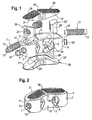
- the expandable intervertebral implant comprises front wall 1, a back wall 2 spaced apart from the front wall, and first side wall 3 connecting the front wall 1 and the back wall 2 at their one end as well as a second side wall 4 opposite to the first side wall for connecting the front wall and the back wall at their opposite other ends.
- the bottom and top faces are open so that the four walls define a cavity 5 having an open bottom and an open top.
- the front wall 1 and the back wall 2 have approximately the same length and are curved in approximately the same direction.
- the sides walls 3 and 4 are shorter and connect the front wall and the back wall in such a way that a substantially banana-shaped or kidney-shaped contour is defined by the walls.
- the length and the curvature of the respective front and back wall and the side walls can be selected so as to be adapted to the size and shape of the opposing end plates of the vertebral bodies between which the implant is to be inserted.
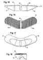
- the height of the front wall and the back wall slightly increases towards the center of the walls (see Figs. 21 to 24 ) in order to be adapted to a corresponding depressed portion of the end plate of the vertebral body.
- the front wall 1 and the back wall 2 have preferably a plurality of apertures 6 which have a diamond shape in the embodiment shown. However, the shape of the apertures can also be circular, oval-shaped or otherwise shaped.
- the side walls 3 and 4 comprise a bore 7, 7' at approximately their center.
- the bore 7 and the corresponding opposite bore 7' each have a first portion 8 with a first bore diameter adjacent to the outside of the side wall, respectively, and a following second portion 9 which opens into the cavity 5 and which has a second bore diameter which is slightly less than the first bore diameter.
- the second portion 9 defines a shoulder.
- a bearing member (or bearing journal) 10, 10' is inserted into the bore 7, 7'.
- Each bearing member 10, 10' has a first cylindrical portion with a first outer diameter and adjacent thereto a second cylindrical portion with a second outer diameter matching the inner diameters of the first portion 8 and the second portion 9 of the bore 7, 7', so that the bearing member rests on the shoulder.
- the size of the bearing member 10, 10' is such, that the bearing member 10, 10' is held in the bore 7, 7', respectively, by press-fitting.
- the implant further comprises two threaded spindles 11, 11', each having a first cylindrical end 12, 12' with a recess 13, 13', preferably a hexagon recess, at the free end for engagement with a tool (not shown).
- the outer diameter of the cylindrical first end 12, 12' is slightly smaller than the inner diameter of the bearing 10, 10' so that first end 12, 12' of the spindle can be inserted into the bearing 10, 10' and can be rotatably held therein.
- Each spindle further has a cylindrical second end 14, 14', opposite to the first end 12, 12'.
- the thread pitches of the threaded spindles 11, 11' are opposite to each other.
- the length of the threaded spindles is such that when the spindles are held in the bearings 10, 10' and project into the cavity 5, the second ends 14, 14' of the spindles do not touch each other.
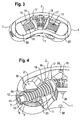
- the coupling member 15 in the embodiment shown in Fig. 1 to 7 is designed as a curved tube portion having slits 16 extending in a circumferential direction.
- the slits are offset from each other in such a way that the slits of one circumferential line cover at least such portions of an adjacent circumferential line, where no slit is provided.
- the inner diameter of the coupling member 15 is such that the coupling member 15 can be connected to the cylindrical end portions 14, 14' of the threaded spindles for example by means of a press-fit connection.
- the curvature and length of the coupling member is such that it is adapted to the angle ⁇ which the longitudinal axis L, L' of the threaded spindles 11, 11' enclose with each other. That means the curvature of the coupling member 15 corresponds substantially to the curvature of the front wall 1 and the back wall 2 of the implant.
- the number, width and length of the slits 16 are selected so as to provide a desired bending flexibility to the tube while providing sufficient torsional stiffness.
- a circular flange 17, 17' can be provided at the end 14, 14' of each spindle 11, 11' to provide a stop the function of which will be described later.
- the flange 17, 17' has a projection 18 on opposite sides which rests on a shoulder 19 provided at the inner side of the front wall 1 and the back wall 2, respectively.
- the flange 17, 17' also provides for a guidance and/or support for the spindles and the coupling member.
- a wedge member 20, 20' is provided on each threaded spindle 11, 11'.
- Each wedge member is defined by a top face 21, 21' and an opposite bottom face 22, 22' which include an angle with each other to define the wedge-shape.
- Each wedge member 20, 20' comprises a flat front wall 23, 23' and a curved rear wall and flat side walls.
- the flat front wall 23, 23' and the top wall 21, 21' and the bottom wall 22, 22' are arranged such that the distance increases between top wall and bottom wall in a direction away from the front wall.
- the wedge member 20, 20' comprises a threaded bore having an internal thread corresponding to the external thread of the threaded spindle 11, 11', respectively.
- the wedge members 20, 20' are screwed onto the corresponding threaded spindles 11, 11' in such a position that their corresponding top faces 21, 21' and bottom faces 22, 22' are inclined towards each other.
- the back walls of the wedge members are curved in such a way that they fit to the curvature of the inner side of the side walls 3, 4 of the implant.
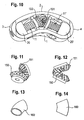
- a first engagement member 30 and a second engagement member 30' is placed between the mutually inclined top faces 21, 21' and mutually inclined bottom faces 22, 22', which will be referred to as wedge faces, of the wedge members 20, 20'.
- Each engagement member 30, 30' has on its lower face facing the wedge members two mutually inclined sloping surfaces 31, 32 and 31', 32', respectively.
- the angle of inclination of the surfaces 31, 32 and 31', 32', respectively, corresponds to the wedge angle of the wedge members.
- the engagement member 30, 30' comprises a substantially curved cylindrical recess 33, 33' which is sized so as to be able to accommodate the coupling member 15 including the flanges 17, 17'.
- the recess 33, 33' runs out into the inclined surfaces 31, 32 and 31', 32', respectively.
- the inclined surfaces of the engagement members 30, 30' and the wedge faces of the wedge members 20, 20' can slide onto each other. To enhance the sliding capability, the faces can be coated with a coating or can be polished.
- the contour of the engagement members is approximately banana-shaped or kidney-shaped and corresponds to the contour of the implant body as shown in Fig. 1 and 2 .
- the top surface 34 of the engagement member 30 has in the embodiment shown a right portion 34a and a left portion 34b which have a slight inclination with respect to each other, the inclination being opposite to the inclination of the inclined surfaces 31, 32 on the lower side.
- the second engagement member 31' has a corresponding top surface 34' with inclined portions 34a', 34b' (not shown).
- the top surface 34 further has an engagement structure 35 which can be designed as teeth projecting from the surface or as ribs or as any other structure which is suitable for engagement with the surface of the end plates of the vertebral body.
- each engagement member 30, 30' comprises a substantially U-shaped slit 36, 36' extending from the top surface 34, 34' to a certain distance therefrom.
- the front wall 1 and the back wall 2 each comprise bores 38, 38' located in the center between the side walls, one in the upper half and one in the lower half.
- Two pins 39, 39' extend through opposite bores 38 across the cavity 5.
- the pins 39, 39' engage the U-shaped slits 36 of the engagement members 30, 30', respectively. By means of this, a stop is formed preventing falling-out of the engagement members 30, 30'.
- the U-shaped slits 36 also form a guidance for the engagement members 30,30'.
- the arrangement of the pins 39, 39' and the depth of the U-shaped slits 36, 36' are matched to each other such that the maximum heights of outward movement of the respective engagement members over the bottom face and the top face is determined by the relative position of the pin 39, 39' and the depth of the slits 36.
- the dimensions of the wedge members 20, 20', the threaded spindles 11, 11' and the engagement members 30, 30' as well as the pitch of the threads is designed so as to allow the engagement members to be displaced from a first position shown in Fig. 21 and 23 in which the top surface 34, 34' is located in the cavity 5 to a second position shown in Fig. 22 and 24 in which the top surface 34, 34' projects above the cavity 5 of the implant.
- the implant is manufactured from a biocompatible material, such as titanium, a biocompatible plastic material or other biocompatible materials.
- the coupling member 15 is for example manufactured from stainless steel or titanium to provide sufficient strength.
- the wedge members 20, 20' are brought into the position shown in Fig. 3 wherein the back walls are in contact with the inner sides of the side walls 34 of the implant by rotating one of the threaded spindles.
- This causes each engagement member 30, 30' to take up its lowermost position wherein the engagement structure 35 of the top surface 34, 34' does not project beyond the cavity 5 of the implant.
- the implant can therefore easily be inserted into the area between two vertebrae and there is no risk of injuring the soft parts of the end plates of the vertebrae. Since the contour of the implant is approximately banana-shaped the insertion is facilitated compared to the insertion of a rectangular implant.
- the implant can be inserted in such a way that the front wall is oriented in the dorsal direction and the back wall is oriented in the ventral direction and the side walls are oriented laterally.
- the indication of the front, back and side wall does not limit the use of the implant to the particular way of insertion and is merely for the distinction of the walls with respect to each other.
- the coupling member 15 By rotating one of the threaded spindles the rotational movement is transferred by the coupling member 15 to the other threaded spindle.
- the coupling member has due to its slits 16 which form weakened portions, a bending capability with sufficient torsional stiffness which allows to transfer the rotational motion of one spindle to the other spindle.
- the mutually inclined wedge surfaces 21, 22 and 21', 22' of the two opposed wedge members 20, 20' exert a force onto the inclined surfaces 31, 32 and 31', 32' of the corresponding engagement members 30, 30' to raise the same until the engagement structure 35 of the top surface 34, 34' projects out of the cavity 5 to thereby engage the end plates of the respective vertebrae.
- the lifting movement of the engagement members 30, 30' is limited by the stop formed by the pins 39, 39' as particularly shown in Fig. 24 .
- the flanges 17, 17' can also provide a stop for the movement of the wedge members.
- the transmission of the rotation of the tool through one threaded spindle to the other threaded spindle and from the wedge members to the engagement members allows a precise adjustment of the expansion of the engagement members and allows for an individual adaptation of the implant to the anatomical shape of the end plates of the vertebrae of the individual patient.
- the threaded spindles prevent the engagement members from becoming loose by themselves.
- the engagement members 30, 30' can be retracted only by backward rotation using a tool whereby the pressure exerted by the vertebrae onto the engagement members forces the engagement members back into the cavity 5 of the implant. This releases the engagement structure from the end plates of the vertebrae.
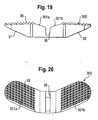
- Fig. 19 and 20 show an alternative embodiment of the engagement member.
- the engagement member 300 differs from the engagement member 30, 30' in that it has two opposed slanted surfaces 301a, 301b adjacent to the U-shaped recess 36 the inclination of which can be parallel to the inclination of the inclined surfaces 31, 32 on the lower side of the engagement member 300.
- the slanted surfaces 301a, 301b do not have an engagement structure.
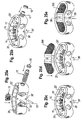
- the coupling mechanism can be formed by a bevel gear drive comprising two pinions 150, 151 engaging each other. Each pinion is non-rotatably connected to the spindles 11, 11'.
- FIG. 13 and 14 A further modified embodiment of the coupling mechanism for transferring the rotational movement of one spindle to the other spindle is shown in Fig. 13 and 14 .
- It comprises a flexible tube 160 which has a curvature and dimensions similar to the coupling member 15 shown in Fig. 1 to 7 and which is sized so as to be press-fit connected to the ends 14, 14' of the spindles.
- the coupling member 160 transfers the rotational movement by a deformation of the flexible material.
- the coupling member 160 can be made for example, from nitinol or flexible plastic material with bending flexibility but torsional stiffness.
- Fig. 25a to 25e show steps for assembly of the implant.
- the first spindle with the corresponding wedge-member screwed thereon is inserted into the cavity and the corresponding bearing.
- the coupling member 15 is connected to the first spindle.
- the second wedge member is inserted, the second spindle guided through the second bore and screwed through the second wedge member until it can be connected with the flange of the coupling member.
- the second bearing is inserted ( Figs. 25a and 25b ).
- the engagement members can be inserted and the pins 39, 39' put through the bores 38, 38', as shown in Fig. 25e .
- the walls are described as front wall, back wall and side walls, this is not to be understood as a limitation for the orientation of the implant between the vertebrae.
- the shape of the implant is not restricted to a banana shape or kidney shape.
- the shape can be ring-shaped or a quarter ring or a half ring or any other shape.
- wedge members on more than two supporting members are provided enclosing an angle with each other.
- three support spindles enclosing an angle of 120° with each other and three adjustment or wedge members can be provided.
Landscapes
- Health & Medical Sciences (AREA)
- Engineering & Computer Science (AREA)
- Biomedical Technology (AREA)
- Orthopedic Medicine & Surgery (AREA)
- Neurology (AREA)
- Heart & Thoracic Surgery (AREA)
- Oral & Maxillofacial Surgery (AREA)
- Transplantation (AREA)
- Cardiology (AREA)
- Vascular Medicine (AREA)
- Life Sciences & Earth Sciences (AREA)
- Animal Behavior & Ethology (AREA)
- General Health & Medical Sciences (AREA)
- Public Health (AREA)
- Veterinary Medicine (AREA)
- Prostheses (AREA)
Claims (15)
- Ein expandierbares Zwischenwirbelimplantat, umfassend:eine vordere Wand (1),eine hintere Wand (2), die von der vorderen Wand beabstandet ist, undzwei Seitenwände (3, 4), welche die vordere Wand (1) und die hintere Wand (2) an ihren entsprechenden Enden miteinander verbinden,wobei die Wände einen Zwischenraum (5) definieren,
eine untere Fläche,
eine obere Fläche,
wenigstens ein Eingriffselement (30, 30') mit einer Eingriffsoberfläche (34, 34') zum Eingriff mit einer Endplatte eines Wirbelkörpers,
ein erstes Einstellelement (20) und zweites Einstellelement (20'), welche durch ein erstes Stützelement (11) und ein zweites Stützelement (11') jeweils entsprechend gestützt werden, und welche mit dem entsprechenden Stützelement zusammenwirken, so dass das Eingriffselement (30, 30') wechselseitig zwischen einer ersten Position, in welcher die Eingriffsoberfläche (34, 34') nicht über die untere Fläche oder die obere Fläche hervorsteht, und einer zweiten Endposition, in welcher die Eingriffsoberfläche (34, 34') zumindest teilweise nach außen über die untere Fläche oder die obere Fläche hinaus übersteht, wechselseitig bewegbar ist,
wobei die ersten und zweiten Stützelemente (111, 11') miteinander durch eine Kopplungsvorrichtung (15; 150, 151; 160) verkoppelt sind,
wobei das erste Stützelement (11) drehbar ist und das zweite Stützelement (11') drehbar ist,
dadurch gekennzeichnet, dass
die Drehachse des ersten Stützelements (11) und die Drehachse des zweiten Stützelements (11') einen von Null verschiedenen Winkel einschließen, und
die Kopplungsvorrichtung (15; 150, 151; 160) die Drehung des ersten Stützelements auf das zweite Stützelement überträgt. - Das Zwischenwirbelimplantat gemäß Anspruch 1, wobei die Kopplungsvorrichtung (15; 150, 151; 160) eine Drehkopplung umfaßt.
- Das Zwischenwirbelimplantat gemäß einem der Ansprüche 1 oder 2, wobei die Kopplungsvorrichtung eine flexible Röhre (15; 160) umfaßt.
- Das Zwischenwirbelimplantat gemäß einem der Ansprüche 1 bis 3, wobei die Kopplungsvorrichtung ein Kegelgetriebe, eine Röhre aus festem Material mit Biegezonen oder einen flexiblen Röhrenantrieb umfaßt.
- Das Zwischenwirbelimplantat gemäß einem der Ansprüche 1 bis 4, wobei die Stützelemente (11, 11') als erste und zweite Gewindespindeln (11, 11') mit entgegen gesetzter Gewindesteigung ausgebildet sind.
- Das Zwischenwirbelimplantat gemäß einem der Ansprüche 1 bis 5, wobei die Einstellelemente (20, 20') Keilelemente sind, wobei die Keilelemente so betrieben werden, dass sie das Eingriffselement (30, 30') bewegen.
- Das Zwischenwirbelimplantat gemäß Anspruch 5, wobei die Einstellelemente (20, 20') als Keilelemente ausgebildet sind und ein Ende (12) der ersten Gewindespindel (11) drehbar in der ersten Seitenwand (3), ein Ende (12') der zweiten Gewindespindel (11') drehbar in der zweiten Seitenwand (4) gelagert ist und die anderen Enden (14, 14') drehbar miteinander verkoppelt sind, und
wobei die zwei Keilelemente in dem Zwischenraum (15) in solcher Weise gehalten werden, dass bei Drehung der ersten oder zweiten Gewindespindel in einer Richtung ein Abstand zwischen den Keilelementen abnimmt und bei Drehung der Gewindespindel in einer entgegen gesetzten Richtung der Abstand zwischen den Keilelementen zunimmt, und wobei die Keilelemente betrieben werden, um das Eingriffselement zu bewegen. - Das Zwischenwirbelimplantat gemäß einem der Ansprüche 5 oder 6, wobei das Eingriffselement (30, 30') auf einer zu den Eingriffsoberflächen (34, 34') entgegen gesetzten Seite geneigte Oberflächen (31, 32; 31', 32') besitzt, und wobei die Keilelemente mit den geneigten Oberflächen in Eingriff stehen.
- Das Zwischenwirbelimplantat gemäß einem der Ansprüche 1 bis 8, wobei zumindest die vordere Wand (1) oder die hintere Wand (2) gekrümmt sind.
- Das Zwischenwirbelimplantat gemäß einem der Ansprüche 1 bis 9, wobei die Wände des Implantats in solcher Weise gekrümmt sind, dass die Kontur des Zwischenraums, welcher durch die Wände gebildet wird, im Wesentlichen bananenförmig ist.
- Das Zwischenwirbelimplantat gemäß einem der Ansprüche 1 bis 10, wobei die Eingriffsoberfläche (34, 34') des Eingriffselements (30, 30') eine Eingriffsstruktur (35) zum Eindringen in ein benachbartes Knochenmaterial umfaßt.
- Ein Zwischenwirbelimplantat gemäß einem der Ansprüche 1 bis 10, ferner umfassend einen Anschlag (36, 39), welcher die Bewegung des Eingriffselements (30, 30') nach außen begrenzt.
- Das Zwischenwirbelimplantat gemäß einem der Ansprüche 1 bis 12, umfassend zwei Eingriffselemente (30, 30'), die in entgegen gesetzten Richtungen bewegbar sind.
- Das Zwischenwirbelimplantat gemäß einem der Ansprüche 1 bis 11, wobei das erste Stützelement (11) und das zweite Stützelement (11') jeweils in einer der Seitenwände (1, 2, 3, 4) gelagert sind.
- Das Zwischenwirbelimplantat gemäß einem der Ansprüche 1 bis 14, wobei die Einstellelemente (20, 20') jeweils durch zwei der Wände (1, 2, 3, 4) geführt werden.
Priority Applications (11)
| Application Number | Priority Date | Filing Date | Title |
|---|---|---|---|
| ES06024332T ES2339472T3 (es) | 2006-11-23 | 2006-11-23 | Implante intervertebral expansible. |
| EP06024332A EP1925272B1 (de) | 2006-11-23 | 2006-11-23 | Expandierbares Zwischenwirbelimplantat |
| DE602006011762T DE602006011762D1 (de) | 2006-11-23 | 2006-11-23 | Expandierbares Zwischenwirbelimplantat |
| TW096143631A TWI422361B (zh) | 2006-11-23 | 2007-11-19 | 可撐張之椎間植入體 |
| JP2007300394A JP5222536B2 (ja) | 2006-11-23 | 2007-11-20 | 伸張可能な椎間インプラント |
| KR1020070118545A KR101465187B1 (ko) | 2006-11-23 | 2007-11-20 | 팽창이 가능한 추간 임플란트 |
| CN2007101927838A CN101185594B (zh) | 2006-11-23 | 2007-11-20 | 可张开的椎间植入物 |
| US11/944,580 US8366777B2 (en) | 2006-11-23 | 2007-11-23 | Expandable intervertebral implant |
| US13/732,032 US8702798B2 (en) | 2006-11-23 | 2012-12-31 | Expandable intervertebral implant |
| US14/176,871 US9662223B2 (en) | 2006-11-23 | 2014-02-10 | Expandable intervertebral implant |
| US15/583,665 US9980823B2 (en) | 2006-11-23 | 2017-05-01 | Expandable intervertebral implant |
Applications Claiming Priority (1)
| Application Number | Priority Date | Filing Date | Title |
|---|---|---|---|
| EP06024332A EP1925272B1 (de) | 2006-11-23 | 2006-11-23 | Expandierbares Zwischenwirbelimplantat |
Publications (2)
| Publication Number | Publication Date |
|---|---|
| EP1925272A1 EP1925272A1 (de) | 2008-05-28 |
| EP1925272B1 true EP1925272B1 (de) | 2010-01-13 |
Family
ID=37950876
Family Applications (1)
| Application Number | Title | Priority Date | Filing Date |
|---|---|---|---|
| EP06024332A Active EP1925272B1 (de) | 2006-11-23 | 2006-11-23 | Expandierbares Zwischenwirbelimplantat |
Country Status (8)
| Country | Link |
|---|---|
| US (4) | US8366777B2 (de) |
| EP (1) | EP1925272B1 (de) |
| JP (1) | JP5222536B2 (de) |
| KR (1) | KR101465187B1 (de) |
| CN (1) | CN101185594B (de) |
| DE (1) | DE602006011762D1 (de) |
| ES (1) | ES2339472T3 (de) |
| TW (1) | TWI422361B (de) |
Cited By (5)
| Publication number | Priority date | Publication date | Assignee | Title |
|---|---|---|---|---|
| US11850160B2 (en) | 2021-03-26 | 2023-12-26 | Medos International Sarl | Expandable lordotic intervertebral fusion cage |
| US11850164B2 (en) | 2013-03-07 | 2023-12-26 | DePuy Synthes Products, Inc. | Intervertebral implant |
| US12318307B2 (en) | 2021-07-16 | 2025-06-03 | Blue Ocean Spine Gmbh | Adjustable spinal implants, associated instruments and methods |
| US12453640B2 (en) | 2021-07-16 | 2025-10-28 | Blue Ocean Spine Gmbh | Adjustable spinal implants, associated instruments and methods |
| US12533242B2 (en) | 2023-01-18 | 2026-01-27 | Blue Ocean Spine Gmbh | Adjustable spinal implants and related deployment instruments |
Families Citing this family (234)
| Publication number | Priority date | Publication date | Assignee | Title |
|---|---|---|---|---|
| US7041309B2 (en) | 2002-06-13 | 2006-05-09 | Neuropro Technologies, Inc. | Spinal fusion using an HMG-CoA reductase inhibitor |
| US6793678B2 (en) | 2002-06-27 | 2004-09-21 | Depuy Acromed, Inc. | Prosthetic intervertebral motion disc having dampening |
| US7828849B2 (en) | 2003-02-03 | 2010-11-09 | Warsaw Orthopedic, Inc. | Expanding interbody implant and articulating inserter and method |
| EP1594423B1 (de) | 2003-02-14 | 2009-01-07 | DePuy Spine, Inc. | In-situ hergestellte intervertebrale fusionsvorrichtung |
| US20040267367A1 (en) | 2003-06-30 | 2004-12-30 | Depuy Acromed, Inc | Intervertebral implant with conformable endplate |
| AU2005212352B2 (en) | 2004-02-09 | 2010-11-18 | Depuy Spine, Inc. | Systems and methods for spinal surgery |
| US8636802B2 (en) | 2004-03-06 | 2014-01-28 | DePuy Synthes Products, LLC | Dynamized interspinal implant |
| WO2005102226A1 (de) | 2004-04-26 | 2005-11-03 | Synthes Gmbh | Zwischenwirbelprothese oder bandscheibenprothese |
| FR2871366A1 (fr) | 2004-06-09 | 2005-12-16 | Ceravic Soc Par Actions Simpli | Implant expansible prothetique osseux |
| WO2006034436A2 (en) | 2004-09-21 | 2006-03-30 | Stout Medical Group, L.P. | Expandable support device and method of use |
| US8597360B2 (en) | 2004-11-03 | 2013-12-03 | Neuropro Technologies, Inc. | Bone fusion device |
| US8092528B2 (en) | 2005-05-27 | 2012-01-10 | Depuy Spine, Inc. | Intervertebral ligament having a helical bone fastener |
| WO2007009107A2 (en) | 2005-07-14 | 2007-01-18 | Stout Medical Group, P.L. | Expandable support device and method of use |
| US9028550B2 (en) | 2005-09-26 | 2015-05-12 | Coalign Innovations, Inc. | Selectively expanding spine cage with enhanced bone graft infusion |
| US20070162132A1 (en) | 2005-12-23 | 2007-07-12 | Dominique Messerli | Flexible elongated chain implant and method of supporting body tissue with same |
| JP5542273B2 (ja) | 2006-05-01 | 2014-07-09 | スタウト メディカル グループ,エル.ピー. | 拡張可能な支持装置および使用方法 |
| US8034110B2 (en) | 2006-07-31 | 2011-10-11 | Depuy Spine, Inc. | Spinal fusion implant |
| US9526525B2 (en) | 2006-08-22 | 2016-12-27 | Neuropro Technologies, Inc. | Percutaneous system for dynamic spinal stabilization |
| WO2008070863A2 (en) | 2006-12-07 | 2008-06-12 | Interventional Spine, Inc. | Intervertebral implant |
| US8142479B2 (en) * | 2007-05-01 | 2012-03-27 | Spinal Simplicity Llc | Interspinous process implants having deployable engagement arms |
| US8273124B2 (en) | 2007-05-17 | 2012-09-25 | Depuy Spine, Inc. | Self-distracting cage |
| US8900307B2 (en) | 2007-06-26 | 2014-12-02 | DePuy Synthes Products, LLC | Highly lordosed fusion cage |
| IES20080551A2 (en) * | 2007-07-03 | 2009-01-07 | Sota Orthopaedics Ltd | A bolt apparatus |
| US20090088789A1 (en) | 2007-09-28 | 2009-04-02 | O'neil Michael J | Balloon With Shape Control For Spinal Procedures |
| AU2009205896A1 (en) | 2008-01-17 | 2009-07-23 | Synthes Gmbh | An expandable intervertebral implant and associated method of manufacturing the same |
| US8932355B2 (en) | 2008-02-22 | 2015-01-13 | Coalign Innovations, Inc. | Spinal implant with expandable fixation |
| US20100145455A1 (en) | 2008-12-10 | 2010-06-10 | Innvotec Surgical, Inc. | Lockable spinal implant |
| US8992620B2 (en) | 2008-12-10 | 2015-03-31 | Coalign Innovations, Inc. | Adjustable distraction cage with linked locking mechanisms |
| US12232975B2 (en) | 2008-02-22 | 2025-02-25 | Howmedica Osteonics Corp. | Lockable spinal implant |
| US8267939B2 (en) | 2008-02-28 | 2012-09-18 | Stryker Spine | Tool for implanting expandable intervertebral implant |
| AU2009231637A1 (en) | 2008-04-05 | 2009-10-08 | Synthes Gmbh | Expandable intervertebral implant |
| WO2009125242A1 (en) * | 2008-04-08 | 2009-10-15 | Vexim | Apparatus for restoration of the spine and methods of use thereof |
| US20100010633A1 (en) * | 2008-07-10 | 2010-01-14 | Kyphon Sarl | Deployable Arc Fusion Cage and Methods Associated Therewith |
| WO2010019799A1 (en) * | 2008-08-13 | 2010-02-18 | Smed-Ta/Td, Llc | Orthopaedic implant with porous structural member |
| WO2010019781A1 (en) | 2008-08-13 | 2010-02-18 | Smed-Ta/Td, Llc | Drug delivery implants |
| US9700431B2 (en) * | 2008-08-13 | 2017-07-11 | Smed-Ta/Td, Llc | Orthopaedic implant with porous structural member |
| US9616205B2 (en) | 2008-08-13 | 2017-04-11 | Smed-Ta/Td, Llc | Drug delivery implants |
| US10842645B2 (en) | 2008-08-13 | 2020-11-24 | Smed-Ta/Td, Llc | Orthopaedic implant with porous structural member |
| WO2010025386A1 (en) | 2008-08-29 | 2010-03-04 | Smed-Ta/Td, Llc | Orthopaedic implant |
| US8545566B2 (en) * | 2008-10-13 | 2013-10-01 | Globus Medical, Inc. | Articulating spacer |
| US8147554B2 (en) * | 2008-10-13 | 2012-04-03 | Globus Medical, Inc. | Intervertebral spacer |
| US20100211176A1 (en) | 2008-11-12 | 2010-08-19 | Stout Medical Group, L.P. | Fixation device and method |
| WO2010056895A1 (en) | 2008-11-12 | 2010-05-20 | Stout Medical Group, L.P. | Fixation device and method |
| BRPI0924440B8 (pt) | 2009-03-12 | 2021-06-22 | Vexim | implante expansível vertebral |
| US9757164B2 (en) | 2013-01-07 | 2017-09-12 | Spinal Simplicity Llc | Interspinous process implant having deployable anchor blades |
| US9861399B2 (en) | 2009-03-13 | 2018-01-09 | Spinal Simplicity, Llc | Interspinous process implant having a body with a removable end portion |
| US9220547B2 (en) | 2009-03-27 | 2015-12-29 | Spinal Elements, Inc. | Flanged interbody fusion device |
| US9526620B2 (en) | 2009-03-30 | 2016-12-27 | DePuy Synthes Products, Inc. | Zero profile spinal fusion cage |
| US9642722B2 (en) | 2009-07-02 | 2017-05-09 | Atlas Spine, Inc. | Intervertebral expandable spacer |
| CN105342683B (zh) | 2009-07-06 | 2018-02-13 | 斯恩蒂斯有限公司 | 可膨胀固定组件 |
| US10973656B2 (en) | 2009-09-18 | 2021-04-13 | Spinal Surgical Strategies, Inc. | Bone graft delivery system and method for using same |
| US10245159B1 (en) | 2009-09-18 | 2019-04-02 | Spinal Surgical Strategies, Llc | Bone graft delivery system and method for using same |
| US8906028B2 (en) | 2009-09-18 | 2014-12-09 | Spinal Surgical Strategies, Llc | Bone graft delivery device and method of using the same |
| US8062375B2 (en) * | 2009-10-15 | 2011-11-22 | Globus Medical, Inc. | Expandable fusion device and method of installation thereof |
| US8709086B2 (en) | 2009-10-15 | 2014-04-29 | Globus Medical, Inc. | Expandable fusion device and method of installation thereof |
| US9155628B2 (en) * | 2009-10-15 | 2015-10-13 | Globus Medical, Inc. | Expandable fusion device and method of installation thereof |
| US11344430B2 (en) * | 2009-10-15 | 2022-05-31 | Globus Medical, Inc. | Expandable fusion device and method of installation thereof |
| US9028553B2 (en) | 2009-11-05 | 2015-05-12 | DePuy Synthes Products, Inc. | Self-pivoting spinal implant and associated instrumentation |
| US9393129B2 (en) | 2009-12-10 | 2016-07-19 | DePuy Synthes Products, Inc. | Bellows-like expandable interbody fusion cage |
| US8894712B2 (en) * | 2010-01-11 | 2014-11-25 | Innova Spinal Technologies, Llc | Expandable intervertebral implant and associated surgical method |
| US8894711B2 (en) * | 2010-01-11 | 2014-11-25 | Innova Spinal Technologies, Llc | Expandable intervertebral implant and associated surgical method |
| US8795366B2 (en) * | 2010-01-11 | 2014-08-05 | Innova Spinal Technologies, Llc | Expandable intervertebral implant and associated surgical method |
| US8353963B2 (en) * | 2010-01-12 | 2013-01-15 | Globus Medical | Expandable spacer and method for use thereof |
| WO2011111301A1 (ja) * | 2010-03-09 | 2011-09-15 | 国立大学法人神戸大学 | 棘突起間インプラント |
| EP2547292B1 (de) | 2010-03-16 | 2019-04-24 | Pinnacle Spine Group, LLC | Zwischenwirbelimplantate sowie implantateinsatzsysteme |
| US8535380B2 (en) * | 2010-05-13 | 2013-09-17 | Stout Medical Group, L.P. | Fixation device and method |
| US8317866B2 (en) * | 2010-06-02 | 2012-11-27 | Warsaw Orthopedic, Inc. | System and methods for a laterally expanding implant |
| US8979860B2 (en) | 2010-06-24 | 2015-03-17 | DePuy Synthes Products. LLC | Enhanced cage insertion device |
| US9763678B2 (en) | 2010-06-24 | 2017-09-19 | DePuy Synthes Products, Inc. | Multi-segment lateral cage adapted to flex substantially in the coronal plane |
| AU2011271465B2 (en) | 2010-06-29 | 2015-03-19 | Synthes Gmbh | Distractible intervertebral implant |
| EP2608747A4 (de) | 2010-08-24 | 2015-02-11 | Flexmedex Llc | Stützvorrichtung und verfahren zu ihrer verwendung |
| US9855151B2 (en) * | 2010-09-03 | 2018-01-02 | Globus Medical, Inc | Expandable fusion device and method of installation thereof |
| US9474625B2 (en) * | 2010-09-03 | 2016-10-25 | Globus Medical, Inc | Expandable fusion device and method of installation thereof |
| US20120078372A1 (en) | 2010-09-23 | 2012-03-29 | Thomas Gamache | Novel implant inserter having a laterally-extending dovetail engagement feature |
| US9402732B2 (en) | 2010-10-11 | 2016-08-02 | DePuy Synthes Products, Inc. | Expandable interspinous process spacer implant |
| US9149286B1 (en) | 2010-11-12 | 2015-10-06 | Flexmedex, LLC | Guidance tool and method for use |
| US8377140B2 (en) | 2011-01-12 | 2013-02-19 | Ebi, Llc | Expandable spinal implant device |
| US8740980B2 (en) | 2011-01-27 | 2014-06-03 | Warsaw Orthopedic, Inc. | Expandable medical implant |
| US8394129B2 (en) | 2011-03-10 | 2013-03-12 | Interventional Spine, Inc. | Method and apparatus for minimally invasive insertion of intervertebral implants |
| US8518087B2 (en) | 2011-03-10 | 2013-08-27 | Interventional Spine, Inc. | Method and apparatus for minimally invasive insertion of intervertebral implants |
| WO2012125382A1 (en) * | 2011-03-11 | 2012-09-20 | FBC Device ApS | Spinal implant, instrument for preparation and method of use |
| AU2012231108B2 (en) | 2011-03-22 | 2015-10-22 | DePuy Synthes Products, LLC | Universal trial for lateral cages |
| CN103841909B (zh) | 2011-04-07 | 2017-02-15 | 维克辛姆公司 | 可张开矫形设备 |
| DE102011002076A1 (de) * | 2011-04-15 | 2012-10-18 | Z.-Medical Gmbh & Co. Kg | Zwischenwirbelimplantat und Vorrichtung zum Einbringen |
| US9066813B2 (en) * | 2011-06-03 | 2015-06-30 | Biomet Spine, Llc | Unidirectional dynamic interbody fusion device and method of use |
| EP2535021B1 (de) * | 2011-06-14 | 2015-10-14 | Biedermann Technologies GmbH & Co. KG | Bandscheibenimplantat |
| WO2012174526A1 (en) * | 2011-06-17 | 2012-12-20 | Mcafee Paul C | Expandable spinal implant and flexible driver |
| WO2013006669A2 (en) * | 2011-07-05 | 2013-01-10 | Expanding Orthopedics Inc. | Bone structural device |
| WO2013023096A1 (en) | 2011-08-09 | 2013-02-14 | Neuropro Technologies, Inc. | Bone fusion device, system and method |
| US10420654B2 (en) | 2011-08-09 | 2019-09-24 | Neuropro Technologies, Inc. | Bone fusion device, system and method |
| WO2013023098A1 (en) | 2011-08-09 | 2013-02-14 | Neuropro Spinal Jaxx Inc. | Bone fusion device, apparatus and method |
| US9320610B2 (en) | 2011-08-16 | 2016-04-26 | Stryker European Holdings I, Llc | Expandable implant |
| JP2014529445A (ja) | 2011-08-23 | 2014-11-13 | フレックスメデックス,エルエルシー | 組織除去装置及び方法 |
| US9248028B2 (en) | 2011-09-16 | 2016-02-02 | DePuy Synthes Products, Inc. | Removable, bone-securing cover plate for intervertebral fusion cage |
| US8864833B2 (en) * | 2011-09-30 | 2014-10-21 | Globus Medical, Inc. | Expandable fusion device and method of installation thereof |
| US9380932B1 (en) | 2011-11-02 | 2016-07-05 | Pinnacle Spine Group, Llc | Retractor devices for minimally invasive access to the spine |
| US9233007B2 (en) * | 2012-02-13 | 2016-01-12 | Blue Tip Biologics, Llc | Expandable self-anchoring interbody cage for orthopedic applications |
| EP2830542B1 (de) * | 2012-03-28 | 2021-10-27 | Innova Spinal Technologies, LLC | Dehnbares bandscheibenimplantat |
| US9381011B2 (en) | 2012-03-29 | 2016-07-05 | Depuy (Ireland) | Orthopedic surgical instrument for knee surgery |
| US9693876B1 (en) | 2012-03-30 | 2017-07-04 | Ali H. MESIWALA | Spinal fusion implant and related methods |
| US9532883B2 (en) | 2012-04-13 | 2017-01-03 | Neuropro Technologies, Inc. | Bone fusion device |
| US10159583B2 (en) | 2012-04-13 | 2018-12-25 | Neuropro Technologies, Inc. | Bone fusion device |
| US9622876B1 (en) * | 2012-04-25 | 2017-04-18 | Theken Spine, Llc | Expandable support device and method of use |
| US8940052B2 (en) | 2012-07-26 | 2015-01-27 | DePuy Synthes Products, LLC | Expandable implant |
| US20140067069A1 (en) | 2012-08-30 | 2014-03-06 | Interventional Spine, Inc. | Artificial disc |
| US8663332B1 (en) | 2012-12-13 | 2014-03-04 | Ouroboros Medical, Inc. | Bone graft distribution system |
| US10022245B2 (en) | 2012-12-17 | 2018-07-17 | DePuy Synthes Products, Inc. | Polyaxial articulating instrument |
| US9974664B2 (en) | 2013-01-24 | 2018-05-22 | Biospine, Llc | Adjustable interbody fusion device and method of use |
| US9782265B2 (en) * | 2013-02-15 | 2017-10-10 | Globus Medical, Inc | Articulating and expandable vertebral implant |
| US9492288B2 (en) | 2013-02-20 | 2016-11-15 | Flexuspine, Inc. | Expandable fusion device for positioning between adjacent vertebral bodies |
| US10117754B2 (en) * | 2013-02-25 | 2018-11-06 | Globus Medical, Inc. | Expandable intervertebral implant |
| US9717601B2 (en) * | 2013-02-28 | 2017-08-01 | DePuy Synthes Products, Inc. | Expandable intervertebral implant, system, kit and method |
| US10004607B2 (en) | 2013-03-01 | 2018-06-26 | Globus Medical, Inc. | Articulating expandable intervertebral implant |
| US9554918B2 (en) * | 2013-03-01 | 2017-01-31 | Globus Medical, Inc. | Articulating expandable intervertebral implant |
| US9204972B2 (en) | 2013-03-01 | 2015-12-08 | Globus Medical, Inc. | Articulating expandable intervertebral implant |
| US9198772B2 (en) * | 2013-03-01 | 2015-12-01 | Globus Medical, Inc. | Articulating expandable intervertebral implant |
| US9770343B2 (en) | 2013-03-01 | 2017-09-26 | Globus Medical Inc. | Articulating expandable intervertebral implant |
| US10342675B2 (en) | 2013-03-11 | 2019-07-09 | Stryker European Holdings I, Llc | Expandable implant |
| US9277928B2 (en) | 2013-03-11 | 2016-03-08 | Interventional Spine, Inc. | Method and apparatus for minimally invasive insertion of intervertebral implants |
| US12193948B2 (en) | 2013-03-13 | 2025-01-14 | Life Spine, Inc. | Expandable implant assembly |
| US10426632B2 (en) | 2013-03-13 | 2019-10-01 | Life Spine, Inc. | Expandable spinal interbody assembly |
| US10292832B2 (en) | 2013-03-14 | 2019-05-21 | Ohio State Innovation Foundation | Spinal fixation device |
| US9993353B2 (en) | 2013-03-14 | 2018-06-12 | DePuy Synthes Products, Inc. | Method and apparatus for minimally invasive insertion of intervertebral implants |
| WO2014159739A1 (en) | 2013-03-14 | 2014-10-02 | Pinnacle Spine Group, Llc | Interbody implants and graft delivery systems |
| US9707096B2 (en) * | 2013-03-14 | 2017-07-18 | K2M, Inc. | Spinal fixation device |
| EP2967659B1 (de) | 2013-03-15 | 2021-03-03 | Neuropro Technologies, Inc. | Körperlose knochenfusionsvorrichtung |
| US9186258B2 (en) * | 2013-03-15 | 2015-11-17 | Globus Medical, Inc. | Expandable intervertebral implant |
| US9463099B2 (en) * | 2013-03-15 | 2016-10-11 | Expanding Orthopedics Inc. | Orthopedic expandable devices |
| WO2014145995A2 (en) | 2013-03-15 | 2014-09-18 | Spectrum Spine Ip Holdings, Llc | Expandable inter-body fusion devices and methods |
| US9119726B2 (en) * | 2013-03-18 | 2015-09-01 | Chih-Hsuan Wei | Expandable implant of a minimally invasive surgery |
| US9393130B2 (en) | 2013-05-20 | 2016-07-19 | K2M, Inc. | Adjustable implant and insertion tool |
| US9788971B1 (en) | 2013-05-22 | 2017-10-17 | Nuvasive, Inc. | Expandable fusion implant and related methods |
| JP6479006B2 (ja) * | 2013-08-09 | 2019-03-06 | グローバス メディカル インコーポレイティッド | 関節接合式拡張可能な椎間インプラント |
| US9801734B1 (en) | 2013-08-09 | 2017-10-31 | Nuvasive, Inc. | Lordotic expandable interbody implant |
| US9566167B2 (en) | 2013-08-22 | 2017-02-14 | K2M, Inc. | Expandable spinal implant |
| US11452614B2 (en) | 2013-08-29 | 2022-09-27 | Adcura, Inc. | Expandable and adjustable lordosis interbody fusion system |
| DK3038565T3 (da) | 2013-08-29 | 2021-08-09 | Spineex Inc | Udvideligt og justerbart fusionssystem til mellem hvirvellegemer ved lordose |
| US9186259B2 (en) | 2013-09-09 | 2015-11-17 | Ouroboros Medical, Inc. | Expandable trials |
| EP3073969B1 (de) | 2013-11-27 | 2023-08-16 | Howmedica Osteonics Corp. | Strukturstützeinsatz für spinalen fusionscage |
| US9668876B2 (en) | 2013-12-05 | 2017-06-06 | Spinal Elements, Inc. | Expandable interbody device |
| FR3015221B1 (fr) | 2013-12-23 | 2017-09-01 | Vexim | Systeme d'implant intravertebral expansible avec fixation pediculaire posterieure |
| US9839528B2 (en) | 2014-02-07 | 2017-12-12 | Globus Medical, Inc. | Variable lordosis spacer and related methods of use |
| WO2015200058A1 (en) * | 2014-06-25 | 2015-12-30 | Spine Wave, Inc. | Expandable interbody fusion device with nested correction surface |
| TWI572320B (zh) | 2014-07-22 | 2017-03-01 | Automatic elastic expansion of vertebral implants | |
| FR3026294A1 (fr) * | 2014-09-30 | 2016-04-01 | Yellowsteps | Cage intersomatique a couvercle ajustable et procede de fabrication afferent |
| US9585762B2 (en) | 2014-10-09 | 2017-03-07 | K2M, Inc. | Expandable spinal interbody spacer and method of use |
| WO2016069796A1 (en) | 2014-10-28 | 2016-05-06 | Spectrum Spine Ip Holdings, Llc | Expandable, adjustable inter-body fusion devices and methods |
| US10575964B2 (en) | 2014-10-28 | 2020-03-03 | Spectrum Spine Ip Holdings, Llc | Expandable, adjustable inter-body fusion devices and methods |
| US10363142B2 (en) | 2014-12-11 | 2019-07-30 | K2M, Inc. | Expandable spinal implants |
| US9060876B1 (en) | 2015-01-20 | 2015-06-23 | Ouroboros Medical, Inc. | Stabilized intervertebral scaffolding systems |
| US11426290B2 (en) | 2015-03-06 | 2022-08-30 | DePuy Synthes Products, Inc. | Expandable intervertebral implant, system, kit and method |
| US10709570B2 (en) | 2015-04-29 | 2020-07-14 | Institute for Musculoskeletal Science and Education, Ltd. | Implant with a diagonal insertion axis |
| US10449051B2 (en) | 2015-04-29 | 2019-10-22 | Institute for Musculoskeletal Science and Education, Ltd. | Implant with curved bone contacting elements |
| EP3288501B1 (de) | 2015-04-29 | 2020-11-25 | Institute For Musculoskeletal Science And Education, Ltd. | Spulenimplantate |
| US10492921B2 (en) | 2015-04-29 | 2019-12-03 | Institute for Musculoskeletal Science and Education, Ltd. | Implant with arched bone contacting elements |
| EP3095416A1 (de) * | 2015-05-18 | 2016-11-23 | Life Spine, Inc. | Expandierbarer wirbelkörper und zwischenwirbelkörpervorrichtungen |
| US9913727B2 (en) | 2015-07-02 | 2018-03-13 | Medos International Sarl | Expandable implant |
| CN105342729B (zh) * | 2015-12-09 | 2017-05-24 | 北京市富乐科技开发有限公司 | 一种弧形撑开融合器 |
| US10973650B2 (en) * | 2015-12-30 | 2021-04-13 | Nuvasive, Inc. | Lordotic expandable fusion implant |
| EP3195833B1 (de) * | 2016-01-19 | 2022-01-12 | K2M, Inc. | Chirurgisches instrument |
| JP6180565B1 (ja) * | 2016-02-23 | 2017-08-16 | 合碩生技股▲分▼有限公司 | 骨格固定装置 |
| US10004608B2 (en) | 2016-02-26 | 2018-06-26 | K2M, Inc. | Insertion instrument for expandable spinal implants |
| CN105769391B (zh) * | 2016-04-05 | 2017-11-03 | 广州爱锘德医疗器械有限公司 | 椎体融合器 |
| US10548738B2 (en) | 2016-04-07 | 2020-02-04 | Howmedica Osteonics Corp. | Expandable interbody implant |
| AU2017203369B2 (en) | 2016-05-20 | 2022-04-28 | Vb Spine Us Opco Llc | Expandable interbody implant with lordosis correction |
| US11596522B2 (en) | 2016-06-28 | 2023-03-07 | Eit Emerging Implant Technologies Gmbh | Expandable and angularly adjustable intervertebral cages with articulating joint |
| EP4233801B1 (de) | 2016-06-28 | 2025-11-05 | Eit Emerging Implant Technologies GmbH | Expandierbare, winkeleinstellbare bandscheiben-cages |
| AU2017228529B2 (en) | 2016-09-12 | 2022-03-10 | Vb Spine Us Opco Llc | Interbody implant with independent control of expansion at multiple locations |
| US9883953B1 (en) | 2016-09-21 | 2018-02-06 | Integrity Implants Inc. | Stabilized laterovertically-expanding fusion cage systems with tensioner |
| US10478312B2 (en) | 2016-10-25 | 2019-11-19 | Institute for Musculoskeletal Science and Education, Ltd. | Implant with protected fusion zones |
| US11033394B2 (en) | 2016-10-25 | 2021-06-15 | Institute for Musculoskeletal Science and Education, Ltd. | Implant with multi-layer bone interfacing lattice |
| AU2017251734B2 (en) | 2016-10-26 | 2022-10-20 | Vb Spine Us Opco Llc | Expandable interbody implant with lateral articulation |
| US10537436B2 (en) * | 2016-11-01 | 2020-01-21 | DePuy Synthes Products, Inc. | Curved expandable cage |
| US10888433B2 (en) | 2016-12-14 | 2021-01-12 | DePuy Synthes Products, Inc. | Intervertebral implant inserter and related methods |
| TWM558049U (zh) * | 2017-01-06 | 2018-04-11 | 克菱生技有限公司 | 可撐開式脊椎填充塊 |
| US10682239B2 (en) | 2017-01-06 | 2020-06-16 | Ke Ling Biotech Limited | Expandable spinal interbody cage |
| EP4623870A3 (de) | 2017-01-10 | 2025-12-24 | Integrity Implants Inc. | Expandierbare intervertebrale fusionsvorrichtung |
| US10729560B2 (en) | 2017-01-18 | 2020-08-04 | Neuropro Technologies, Inc. | Bone fusion system, device and method including an insertion instrument |
| US10973657B2 (en) | 2017-01-18 | 2021-04-13 | Neuropro Technologies, Inc. | Bone fusion surgical system and method |
| US10213321B2 (en) | 2017-01-18 | 2019-02-26 | Neuropro Technologies, Inc. | Bone fusion system, device and method including delivery apparatus |
| US10111760B2 (en) | 2017-01-18 | 2018-10-30 | Neuropro Technologies, Inc. | Bone fusion system, device and method including a measuring mechanism |
| US10111755B2 (en) * | 2017-02-24 | 2018-10-30 | Warsaw, Orthopedic, Inc. | Expanding interbody implant and articulating inserter and methods of use |
| US10512549B2 (en) | 2017-03-13 | 2019-12-24 | Institute for Musculoskeletal Science and Education, Ltd. | Implant with structural members arranged around a ring |
| US10357377B2 (en) | 2017-03-13 | 2019-07-23 | Institute for Musculoskeletal Science and Education, Ltd. | Implant with bone contacting elements having helical and undulating planar geometries |
| US10470894B2 (en) * | 2017-04-06 | 2019-11-12 | Warsaw Orthopedic, Inc. | Expanding interbody implant and articulating inserter and methods of use |
| US10398563B2 (en) | 2017-05-08 | 2019-09-03 | Medos International Sarl | Expandable cage |
| US11344424B2 (en) | 2017-06-14 | 2022-05-31 | Medos International Sarl | Expandable intervertebral implant and related methods |
| US9962272B1 (en) | 2017-06-28 | 2018-05-08 | Amendia, Inc. | Intervertebral implant device with lordotic expansion |
| US10940016B2 (en) | 2017-07-05 | 2021-03-09 | Medos International Sarl | Expandable intervertebral fusion cage |
| US11896494B2 (en) | 2017-07-10 | 2024-02-13 | Life Spine, Inc. | Expandable implant assembly |
| US10966843B2 (en) | 2017-07-18 | 2021-04-06 | DePuy Synthes Products, Inc. | Implant inserters and related methods |
| WO2019023251A1 (en) | 2017-07-24 | 2019-01-31 | Integrity Implants, Inc. | SURGICAL IMPLANT AND ASSOCIATED METHODS |
| US10441430B2 (en) | 2017-07-24 | 2019-10-15 | K2M, Inc. | Expandable spinal implants |
| US11045331B2 (en) | 2017-08-14 | 2021-06-29 | DePuy Synthes Products, Inc. | Intervertebral implant inserters and related methods |
| US10709578B2 (en) | 2017-08-25 | 2020-07-14 | Integrity Implants Inc. | Surgical biologics delivery system and related methods |
| EP3456294B1 (de) | 2017-09-15 | 2024-06-05 | Stryker European Operations Holdings LLC | Mit aushärtendem material expandierte zwischenwirbelkörperfusionsvorrichtung |
| US11013610B2 (en) * | 2017-10-18 | 2021-05-25 | Spine Wave, Inc. | Expandable anterior lumbar interbody fusion device |
| US10709569B2 (en) * | 2017-11-09 | 2020-07-14 | Globus Medical, Inc. | Expandable intervertebral implant |
| US10722379B2 (en) * | 2017-11-09 | 2020-07-28 | Globus Medical, Inc. | Expandable intervertebral implant |
| US10940015B2 (en) | 2017-11-21 | 2021-03-09 | Institute for Musculoskeletal Science and Education, Ltd. | Implant with improved flow characteristics |
| US10744001B2 (en) | 2017-11-21 | 2020-08-18 | Institute for Musculoskeletal Science and Education, Ltd. | Implant with improved bone contact |
| EP3742990B1 (de) | 2018-03-01 | 2026-02-11 | Integrity Implants Inc. | Expandierbare fusionsvorrichtung mit unabhängigen expansionssystemen |
| US11382769B2 (en) | 2018-09-20 | 2022-07-12 | Spinal Elements, Inc. | Spinal implant device |
| SG11202102465QA (en) * | 2018-09-26 | 2021-04-29 | Spineex Inc | Expandable and adjustable lordosis interbody fusion system |
| US11446156B2 (en) | 2018-10-25 | 2022-09-20 | Medos International Sarl | Expandable intervertebral implant, inserter instrument, and related methods |
| US10722380B1 (en) * | 2019-02-04 | 2020-07-28 | Bret Michael Berry | Laterally expandable spinal implant |
| CN110013366B (zh) * | 2019-04-04 | 2020-04-07 | 珠海维尔康生物科技有限公司 | 一种可植骨高度可调的椎间融合器 |
| EP3979951A1 (de) | 2019-06-10 | 2022-04-13 | Life Spine, Inc. | Expandierbare implantatanordnung mit kompressionsmerkmalen |
| US12042395B2 (en) | 2019-06-11 | 2024-07-23 | Life Spine, Inc. | Expandable implant assembly |
| US11622864B2 (en) | 2019-06-28 | 2023-04-11 | Innovasis, Inc. | Expandable intervertebral implant |
| JP7658950B2 (ja) | 2019-08-15 | 2025-04-08 | アドキュラ・インコーポレーテッド | 変換式の二軸の調整可能な椎体間固定術の脊椎システム |
| EP4013357B1 (de) | 2019-08-15 | 2025-04-23 | Adcura, Inc. | Zweiachsige verstellbare wirbelsäulensysteme und vorrichtungen zur interkorporellen fusion mit fixierung |
| US11648132B2 (en) | 2019-09-24 | 2023-05-16 | Adcura, Inc | Surgical instrument for operating spinal implant system with dual axis adjustability and method of operating same |
| WO2021179011A1 (en) | 2020-03-05 | 2021-09-10 | Orchid Mps Holdings, Llc | Vertically and laterally expandable vertebral cage |
| US11426286B2 (en) | 2020-03-06 | 2022-08-30 | Eit Emerging Implant Technologies Gmbh | Expandable intervertebral implant |
| US11547573B2 (en) * | 2020-04-08 | 2023-01-10 | K2M, Inc. | Expandable interbody implant with teeth driven linkages |
| US11857432B2 (en) | 2020-04-13 | 2024-01-02 | Life Spine, Inc. | Expandable implant assembly |
| US11602439B2 (en) | 2020-04-16 | 2023-03-14 | Life Spine, Inc. | Expandable implant assembly |
| US12336917B2 (en) | 2020-05-15 | 2025-06-24 | Life Spine, Inc. | Steerable implant assembly |
| KR102489197B1 (ko) * | 2020-05-25 | 2023-01-17 | (주)엘앤케이바이오메드 | 높이조절이 가능한 척추 유합 케이지 |
| US11602440B2 (en) | 2020-06-25 | 2023-03-14 | Life Spine, Inc. | Expandable implant assembly |
| US12329652B2 (en) | 2020-07-20 | 2025-06-17 | Integrity Implants Inc. | Expandable fusion device with independent expansion systems |
| US11596524B2 (en) | 2020-07-24 | 2023-03-07 | Warsaw Orthopedic, Inc. | Expanding interbody implant and method |
| US11554021B2 (en) * | 2020-07-24 | 2023-01-17 | Warsaw Orthopedic, Inc. | Expanding interbody implant and method |
| US11554020B2 (en) | 2020-09-08 | 2023-01-17 | Life Spine, Inc. | Expandable implant with pivoting control assembly |
| WO2022109524A1 (en) | 2020-11-19 | 2022-05-27 | Spinal Elements, Inc. | Curved expandable interbody devices and deployment tools |
| WO2022133456A1 (en) | 2020-12-17 | 2022-06-23 | Spinal Elements, Inc. | Spinal implant device |
| WO2022178759A1 (zh) * | 2021-02-25 | 2022-09-01 | 上海三友医疗器械股份有限公司 | 融合器及其安装工具 |
| US11291559B1 (en) * | 2021-03-05 | 2022-04-05 | CTL Amedica Corporation | Expandable interbody fusion device and method of manufacturing the same |
| IT202100005699A1 (it) * | 2021-03-18 | 2022-09-18 | Emmemme S R L S | Dispositivo intersomatico |
| US11752009B2 (en) | 2021-04-06 | 2023-09-12 | Medos International Sarl | Expandable intervertebral fusion cage |
| US12090064B2 (en) | 2022-03-01 | 2024-09-17 | Medos International Sarl | Stabilization members for expandable intervertebral implants, and related systems and methods |
| US12458506B2 (en) | 2022-04-05 | 2025-11-04 | Spine Wave, Inc. | Steerable and expandable interbody fusion device and associated instrumentation |
| EP4633496A1 (de) | 2022-12-13 | 2025-10-22 | Spinal Simplicity, LLC | Medizinisches implantat und einsetzwerkzeug |
Family Cites Families (16)
| Publication number | Priority date | Publication date | Assignee | Title |
|---|---|---|---|---|
| JPH0251751A (ja) | 1988-08-16 | 1990-02-21 | Nec Corp | Ram制御回路 |
| JPH0251751U (de) * | 1988-10-05 | 1990-04-12 | ||
| US5658335A (en) * | 1995-03-09 | 1997-08-19 | Cohort Medical Products Group, Inc. | Spinal fixator |
| DE19807236C2 (de) | 1998-02-20 | 2000-06-21 | Biedermann Motech Gmbh | Zwischenwirbelimplantat |
| US6530936B1 (en) * | 1998-06-03 | 2003-03-11 | Yeong Seok Yun | Apparatus for harvesting cartilage |
| WO2002009626A1 (en) * | 1999-07-26 | 2002-02-07 | Advanced Prosthetic Technologies, Inc. | Improved spinal surgical prosthesis |
| US6974480B2 (en) | 2001-05-03 | 2005-12-13 | Synthes (Usa) | Intervertebral implant for transforaminal posterior lumbar interbody fusion procedure |
| US6723126B1 (en) * | 2002-11-01 | 2004-04-20 | Sdgi Holdings, Inc. | Laterally expandable cage |
| US7828849B2 (en) * | 2003-02-03 | 2010-11-09 | Warsaw Orthopedic, Inc. | Expanding interbody implant and articulating inserter and method |
| WO2004080356A2 (en) * | 2003-03-07 | 2004-09-23 | Smart Disc, Inc. | Spinal implant with securement spikes |
| US7753958B2 (en) * | 2003-08-05 | 2010-07-13 | Gordon Charles R | Expandable intervertebral implant |
| DE502004010737D1 (de) | 2003-12-09 | 2010-03-25 | Biedermann Motech Gmbh | Höheneinstellbares Zwischenwirbelimplantat |
| US7569074B2 (en) | 2003-12-11 | 2009-08-04 | Warsaw Orthopedic, Inc. | Expandable intervertebral implant |
| US20060095136A1 (en) | 2004-11-03 | 2006-05-04 | Mcluen Design, Inc. | Bone fusion device |
| US7674296B2 (en) * | 2005-04-21 | 2010-03-09 | Globus Medical, Inc. | Expandable vertebral prosthesis |
| US7708779B2 (en) * | 2006-05-01 | 2010-05-04 | Warsaw Orthopedic, Inc. | Expandable intervertebral spacers and methods of use |
-
2006
- 2006-11-23 EP EP06024332A patent/EP1925272B1/de active Active
- 2006-11-23 ES ES06024332T patent/ES2339472T3/es active Active
- 2006-11-23 DE DE602006011762T patent/DE602006011762D1/de active Active
-
2007
- 2007-11-19 TW TW096143631A patent/TWI422361B/zh not_active IP Right Cessation
- 2007-11-20 JP JP2007300394A patent/JP5222536B2/ja not_active Expired - Fee Related
- 2007-11-20 KR KR1020070118545A patent/KR101465187B1/ko not_active Expired - Fee Related
- 2007-11-20 CN CN2007101927838A patent/CN101185594B/zh not_active Expired - Fee Related
- 2007-11-23 US US11/944,580 patent/US8366777B2/en active Active
-
2012
- 2012-12-31 US US13/732,032 patent/US8702798B2/en active Active
-
2014
- 2014-02-10 US US14/176,871 patent/US9662223B2/en active Active
-
2017
- 2017-05-01 US US15/583,665 patent/US9980823B2/en active Active
Cited By (5)
| Publication number | Priority date | Publication date | Assignee | Title |
|---|---|---|---|---|
| US11850164B2 (en) | 2013-03-07 | 2023-12-26 | DePuy Synthes Products, Inc. | Intervertebral implant |
| US11850160B2 (en) | 2021-03-26 | 2023-12-26 | Medos International Sarl | Expandable lordotic intervertebral fusion cage |
| US12318307B2 (en) | 2021-07-16 | 2025-06-03 | Blue Ocean Spine Gmbh | Adjustable spinal implants, associated instruments and methods |
| US12453640B2 (en) | 2021-07-16 | 2025-10-28 | Blue Ocean Spine Gmbh | Adjustable spinal implants, associated instruments and methods |
| US12533242B2 (en) | 2023-01-18 | 2026-01-27 | Blue Ocean Spine Gmbh | Adjustable spinal implants and related deployment instruments |
Also Published As
| Publication number | Publication date |
|---|---|
| US20140257485A1 (en) | 2014-09-11 |
| EP1925272A1 (de) | 2008-05-28 |
| KR101465187B1 (ko) | 2014-11-25 |
| US8702798B2 (en) | 2014-04-22 |
| ES2339472T3 (es) | 2010-05-20 |
| DE602006011762D1 (de) | 2010-03-04 |
| TW200822915A (en) | 2008-06-01 |
| US20170296353A1 (en) | 2017-10-19 |
| US8366777B2 (en) | 2013-02-05 |
| US20080147193A1 (en) | 2008-06-19 |
| US9980823B2 (en) | 2018-05-29 |
| US20130173003A1 (en) | 2013-07-04 |
| JP2008126085A (ja) | 2008-06-05 |
| CN101185594B (zh) | 2011-12-28 |
| KR20080047276A (ko) | 2008-05-28 |
| US9662223B2 (en) | 2017-05-30 |
| JP5222536B2 (ja) | 2013-06-26 |
| TWI422361B (zh) | 2014-01-11 |
| CN101185594A (zh) | 2008-05-28 |
Similar Documents
| Publication | Publication Date | Title |
|---|---|---|
| EP1925272B1 (de) | Expandierbares Zwischenwirbelimplantat | |
| US11291551B2 (en) | Expandable vertebral prosthesis | |
| US11399951B2 (en) | Expandable vertebral prosthesis | |
| US10369002B2 (en) | Expandable vertebral prosthesis | |
| US8197546B2 (en) | Corpectomy implant | |
| AU2003304352B2 (en) | Intervertebral implant comprising dome-shaped joint surfaces | |
| US8337559B2 (en) | Expandable vertebral prosthesis |
Legal Events
| Date | Code | Title | Description |
|---|---|---|---|
| PUAI | Public reference made under article 153(3) epc to a published international application that has entered the european phase |
Free format text: ORIGINAL CODE: 0009012 |
|
| AK | Designated contracting states |
Kind code of ref document: A1 Designated state(s): AT BE BG CH CY CZ DE DK EE ES FI FR GB GR HU IE IS IT LI LT LU LV MC NL PL PT RO SE SI SK TR |
|
| AX | Request for extension of the european patent |
Extension state: AL BA HR MK RS |
|
| 17P | Request for examination filed |
Effective date: 20080521 |
|
| 17Q | First examination report despatched |
Effective date: 20080709 |
|
| AKX | Designation fees paid |
Designated state(s): CH DE ES FR GB IT LI |
|
| GRAP | Despatch of communication of intention to grant a patent |
Free format text: ORIGINAL CODE: EPIDOSNIGR1 |
|
| GRAS | Grant fee paid |
Free format text: ORIGINAL CODE: EPIDOSNIGR3 |
|
| GRAA | (expected) grant |
Free format text: ORIGINAL CODE: 0009210 |
|
| AK | Designated contracting states |
Kind code of ref document: B1 Designated state(s): CH DE ES FR GB IT LI |
|
| REG | Reference to a national code |
Ref country code: GB Ref legal event code: FG4D |
|
| REG | Reference to a national code |
Ref country code: CH Ref legal event code: EP |
|
| REG | Reference to a national code |
Ref country code: CH Ref legal event code: NV Representative=s name: NOVAGRAAF INTERNATIONAL SA |
|
| REF | Corresponds to: |
Ref document number: 602006011762 Country of ref document: DE Date of ref document: 20100304 Kind code of ref document: P |
|
| REG | Reference to a national code |
Ref country code: ES Ref legal event code: FG2A Ref document number: 2339472 Country of ref document: ES Kind code of ref document: T3 |
|
| PLBE | No opposition filed within time limit |
Free format text: ORIGINAL CODE: 0009261 |
|
| STAA | Information on the status of an ep patent application or granted ep patent |
Free format text: STATUS: NO OPPOSITION FILED WITHIN TIME LIMIT |
|
| 26N | No opposition filed |
Effective date: 20101014 |
|
| REG | Reference to a national code |
Ref country code: CH Ref legal event code: PFA Owner name: BIEDERMANN MOTECH GMBH Free format text: BIEDERMANN MOTECH GMBH#BERTHA-VON-SUTTNER-STRASSE 23#78054 VS-SCHWENNINGEN (DE) -TRANSFER TO- BIEDERMANN MOTECH GMBH#BERTHA-VON-SUTTNER-STRASSE 23#78054 VS-SCHWENNINGEN (DE) |
|
| REG | Reference to a national code |
Ref country code: DE Ref legal event code: R082 Ref document number: 602006011762 Country of ref document: DE Representative=s name: PRUEFER & PARTNER GBR, DE |
|
| REG | Reference to a national code |
Ref country code: DE Ref legal event code: R082 Ref document number: 602006011762 Country of ref document: DE Representative=s name: PRUEFER & PARTNER GBR, DE Effective date: 20121128 Ref country code: DE Ref legal event code: R081 Ref document number: 602006011762 Country of ref document: DE Owner name: BIEDERMANN TECHNOLOGIES GMBH & CO. KG, DE Free format text: FORMER OWNER: BIEDERMANN MOTECH GMBH, 78054 VILLINGEN-SCHWENNINGEN, DE Effective date: 20121128 Ref country code: DE Ref legal event code: R082 Ref document number: 602006011762 Country of ref document: DE Representative=s name: PRUEFER & PARTNER MBB PATENTANWAELTE RECHTSANW, DE Effective date: 20121128 |
|
| REG | Reference to a national code |
Ref country code: CH Ref legal event code: PUE Owner name: BIEDERMANN TECHNOLOGIES GMBH AND CO. KG, DE Free format text: FORMER OWNER: BIEDERMANN MOTECH GMBH AND CO. KG, DE Ref country code: CH Ref legal event code: PFA Owner name: BIEDERMANN MOTECH GMBH AND CO. KG, DE Free format text: FORMER OWNER: BIEDERMANN MOTECH GMBH, DE |
|
| REG | Reference to a national code |
Ref country code: ES Ref legal event code: PC2A Owner name: BIEDERMANN MOTECH GMBH & CO.KG. Effective date: 20130205 Ref country code: CH Ref legal event code: PFA Owner name: BIEDERMANN MOTECH GMBH AND CO. KG, DE Free format text: FORMER OWNER: BIEDERMANN MOTECH GMBH, DE Ref country code: CH Ref legal event code: PUE Owner name: BIEDERMANN TECHNOLOGIES GMBH AND CO. KG, DE Free format text: FORMER OWNER: BIEDERMANN MOTECH GMBH AND CO. KG, DE |
|
| REG | Reference to a national code |
Ref country code: ES Ref legal event code: PC2A Owner name: BIEDERMANN TECHNOLOGIES GMBH & CO. KG Effective date: 20130311 |
|
| REG | Reference to a national code |
Ref country code: GB Ref legal event code: 732E Free format text: REGISTERED BETWEEN 20130307 AND 20130313 |
|
| REG | Reference to a national code |
Ref country code: FR Ref legal event code: TP Owner name: BIEDERMANN TECHNOLOGIES GMBH & CO.KG, DE Effective date: 20130329 Ref country code: FR Ref legal event code: CD Owner name: BIEDERMANN TECHNOLOGIES GMBH & CO.KG, DE Effective date: 20130329 |
|
| REG | Reference to a national code |
Ref country code: FR Ref legal event code: PLFP Year of fee payment: 10 |
|
| REG | Reference to a national code |
Ref country code: FR Ref legal event code: PLFP Year of fee payment: 11 |
|
| PGFP | Annual fee paid to national office [announced via postgrant information from national office to epo] |
Ref country code: FR Payment date: 20161124 Year of fee payment: 11 |
|
| PGFP | Annual fee paid to national office [announced via postgrant information from national office to epo] |
Ref country code: IT Payment date: 20161124 Year of fee payment: 11 Ref country code: ES Payment date: 20161124 Year of fee payment: 11 |
|
| REG | Reference to a national code |
Ref country code: FR Ref legal event code: ST Effective date: 20180731 |
|
| PG25 | Lapsed in a contracting state [announced via postgrant information from national office to epo] |
Ref country code: FR Free format text: LAPSE BECAUSE OF NON-PAYMENT OF DUE FEES Effective date: 20171130 Ref country code: IT Free format text: LAPSE BECAUSE OF NON-PAYMENT OF DUE FEES Effective date: 20171123 |
|
| PG25 | Lapsed in a contracting state [announced via postgrant information from national office to epo] |
Ref country code: ES Free format text: LAPSE BECAUSE OF NON-PAYMENT OF DUE FEES Effective date: 20171124 |
|
| P01 | Opt-out of the competence of the unified patent court (upc) registered |
Effective date: 20230525 |
|
| PGFP | Annual fee paid to national office [announced via postgrant information from national office to epo] |
Ref country code: DE Payment date: 20241125 Year of fee payment: 19 |
|
| PGFP | Annual fee paid to national office [announced via postgrant information from national office to epo] |
Ref country code: GB Payment date: 20241121 Year of fee payment: 19 |
|
| PGFP | Annual fee paid to national office [announced via postgrant information from national office to epo] |
Ref country code: CH Payment date: 20241201 Year of fee payment: 19 |