EP4434697A2 - Dispositif de coupe pour étiquettes autocollantes sans bande sans support - Google Patents
Dispositif de coupe pour étiquettes autocollantes sans bande sans support Download PDFInfo
- Publication number
- EP4434697A2 EP4434697A2 EP24192838.1A EP24192838A EP4434697A2 EP 4434697 A2 EP4434697 A2 EP 4434697A2 EP 24192838 A EP24192838 A EP 24192838A EP 4434697 A2 EP4434697 A2 EP 4434697A2
- Authority
- EP
- European Patent Office
- Prior art keywords
- knife
- carriage
- structural unit
- cutting
- extension
- Prior art date
- Legal status (The legal status is an assumption and is not a legal conclusion. Google has not performed a legal analysis and makes no representation as to the accuracy of the status listed.)
- Pending
Links
Images


Classifications
-
- B—PERFORMING OPERATIONS; TRANSPORTING
- B26—HAND CUTTING TOOLS; CUTTING; SEVERING
- B26D—CUTTING; DETAILS COMMON TO MACHINES FOR PERFORATING, PUNCHING, CUTTING-OUT, STAMPING-OUT OR SEVERING
- B26D7/00—Details of apparatus for cutting, cutting-out, stamping-out, punching, perforating, or severing by means other than cutting
- B26D7/26—Means for mounting or adjusting the cutting member; Means for adjusting the stroke of the cutting member
- B26D7/2628—Means for adjusting the position of the cutting member
-
- B—PERFORMING OPERATIONS; TRANSPORTING
- B65—CONVEYING; PACKING; STORING; HANDLING THIN OR FILAMENTARY MATERIAL
- B65H—HANDLING THIN OR FILAMENTARY MATERIAL, e.g. SHEETS, WEBS, CABLES
- B65H35/00—Delivering articles from cutting or line-perforating machines; Article or web delivery apparatus incorporating cutting or line-perforating devices, e.g. adhesive tape dispensers
- B65H35/04—Delivering articles from cutting or line-perforating machines; Article or web delivery apparatus incorporating cutting or line-perforating devices, e.g. adhesive tape dispensers from or with transverse cutters or perforators
- B65H35/06—Delivering articles from cutting or line-perforating machines; Article or web delivery apparatus incorporating cutting or line-perforating devices, e.g. adhesive tape dispensers from or with transverse cutters or perforators from or with blade, e.g. shear-blade, cutters or perforators
-
- B—PERFORMING OPERATIONS; TRANSPORTING
- B26—HAND CUTTING TOOLS; CUTTING; SEVERING
- B26D—CUTTING; DETAILS COMMON TO MACHINES FOR PERFORATING, PUNCHING, CUTTING-OUT, STAMPING-OUT OR SEVERING
- B26D1/00—Cutting through work characterised by the nature or movement of the cutting member or particular materials not otherwise provided for; Apparatus or machines therefor; Cutting members therefor
- B26D1/01—Cutting through work characterised by the nature or movement of the cutting member or particular materials not otherwise provided for; Apparatus or machines therefor; Cutting members therefor involving a cutting member which does not travel with the work
- B26D1/04—Cutting through work characterised by the nature or movement of the cutting member or particular materials not otherwise provided for; Apparatus or machines therefor; Cutting members therefor involving a cutting member which does not travel with the work having a linearly-movable cutting member
- B26D1/045—Cutting through work characterised by the nature or movement of the cutting member or particular materials not otherwise provided for; Apparatus or machines therefor; Cutting members therefor involving a cutting member which does not travel with the work having a linearly-movable cutting member for thin material, e.g. for sheets, strips or the like
-
- B—PERFORMING OPERATIONS; TRANSPORTING
- B26—HAND CUTTING TOOLS; CUTTING; SEVERING
- B26D—CUTTING; DETAILS COMMON TO MACHINES FOR PERFORATING, PUNCHING, CUTTING-OUT, STAMPING-OUT OR SEVERING
- B26D1/00—Cutting through work characterised by the nature or movement of the cutting member or particular materials not otherwise provided for; Apparatus or machines therefor; Cutting members therefor
- B26D1/01—Cutting through work characterised by the nature or movement of the cutting member or particular materials not otherwise provided for; Apparatus or machines therefor; Cutting members therefor involving a cutting member which does not travel with the work
- B26D1/04—Cutting through work characterised by the nature or movement of the cutting member or particular materials not otherwise provided for; Apparatus or machines therefor; Cutting members therefor involving a cutting member which does not travel with the work having a linearly-movable cutting member
- B26D1/06—Cutting through work characterised by the nature or movement of the cutting member or particular materials not otherwise provided for; Apparatus or machines therefor; Cutting members therefor involving a cutting member which does not travel with the work having a linearly-movable cutting member wherein the cutting member reciprocates
- B26D1/065—Cutting through work characterised by the nature or movement of the cutting member or particular materials not otherwise provided for; Apparatus or machines therefor; Cutting members therefor involving a cutting member which does not travel with the work having a linearly-movable cutting member wherein the cutting member reciprocates for thin material, e.g. for sheets, strips or the like
-
- B—PERFORMING OPERATIONS; TRANSPORTING
- B65—CONVEYING; PACKING; STORING; HANDLING THIN OR FILAMENTARY MATERIAL
- B65C—LABELLING OR TAGGING MACHINES, APPARATUS, OR PROCESSES
- B65C9/00—Details of labelling machines or apparatus
- B65C9/08—Label feeding
- B65C9/18—Label feeding from strips, e.g. from rolls
- B65C9/1803—Label feeding from strips, e.g. from rolls the labels being cut from a strip
-
- B—PERFORMING OPERATIONS; TRANSPORTING
- B65—CONVEYING; PACKING; STORING; HANDLING THIN OR FILAMENTARY MATERIAL
- B65H—HANDLING THIN OR FILAMENTARY MATERIAL, e.g. SHEETS, WEBS, CABLES
- B65H35/00—Delivering articles from cutting or line-perforating machines; Article or web delivery apparatus incorporating cutting or line-perforating devices, e.g. adhesive tape dispensers
- B65H35/0006—Article or web delivery apparatus incorporating cutting or line-perforating devices
- B65H35/002—Hand-held or table apparatus
-
- B—PERFORMING OPERATIONS; TRANSPORTING
- B65—CONVEYING; PACKING; STORING; HANDLING THIN OR FILAMENTARY MATERIAL
- B65H—HANDLING THIN OR FILAMENTARY MATERIAL, e.g. SHEETS, WEBS, CABLES
- B65H35/00—Delivering articles from cutting or line-perforating machines; Article or web delivery apparatus incorporating cutting or line-perforating devices, e.g. adhesive tape dispensers
- B65H35/0006—Article or web delivery apparatus incorporating cutting or line-perforating devices
- B65H35/0073—Details
- B65H35/008—Arrangements or adaptations of cutting devices
-
- B—PERFORMING OPERATIONS; TRANSPORTING
- B26—HAND CUTTING TOOLS; CUTTING; SEVERING
- B26D—CUTTING; DETAILS COMMON TO MACHINES FOR PERFORATING, PUNCHING, CUTTING-OUT, STAMPING-OUT OR SEVERING
- B26D7/00—Details of apparatus for cutting, cutting-out, stamping-out, punching, perforating, or severing by means other than cutting
- B26D2007/0012—Details, accessories or auxiliary or special operations not otherwise provided for
- B26D2007/005—Details, accessories or auxiliary or special operations not otherwise provided for cutters, e.g. guillotines, used in a label maker or printer
-
- B—PERFORMING OPERATIONS; TRANSPORTING
- B26—HAND CUTTING TOOLS; CUTTING; SEVERING
- B26D—CUTTING; DETAILS COMMON TO MACHINES FOR PERFORATING, PUNCHING, CUTTING-OUT, STAMPING-OUT OR SEVERING
- B26D7/00—Details of apparatus for cutting, cutting-out, stamping-out, punching, perforating, or severing by means other than cutting
- B26D7/26—Means for mounting or adjusting the cutting member; Means for adjusting the stroke of the cutting member
- B26D2007/2685—Means for mounting or adjusting the cutting member; Means for adjusting the stroke of the cutting member flexible mounting means
-
- B—PERFORMING OPERATIONS; TRANSPORTING
- B65—CONVEYING; PACKING; STORING; HANDLING THIN OR FILAMENTARY MATERIAL
- B65H—HANDLING THIN OR FILAMENTARY MATERIAL, e.g. SHEETS, WEBS, CABLES
- B65H2301/00—Handling processes for sheets or webs
- B65H2301/50—Auxiliary process performed during handling process
- B65H2301/51—Modifying a characteristic of handled material
- B65H2301/515—Cutting handled material
- B65H2301/5153—Details of cutting means
- B65H2301/51532—Blade cutter, e.g. single blade cutter
-
- B—PERFORMING OPERATIONS; TRANSPORTING
- B65—CONVEYING; PACKING; STORING; HANDLING THIN OR FILAMENTARY MATERIAL
- B65H—HANDLING THIN OR FILAMENTARY MATERIAL, e.g. SHEETS, WEBS, CABLES
- B65H2701/00—Handled material; Storage means
- B65H2701/10—Handled articles or webs
- B65H2701/19—Specific article or web
- B65H2701/192—Labels
Definitions
- the invention relates to a cutter for self-adhesive carrier-free endless band labels, with a transport roller that can be rotated about a rotation axis and a knife unit that comprises a knife carriage that can be moved linearly parallel to the rotation axis of the transport roller and a cutting knife that is held in a rotationally fixed manner on the knife carriage and directed towards the transport roller, wherein the endless band labels can be guided through between the transport roller and the knife unit.
- a cutter is known from the document DE 199 58 274 A1 known.
- a cutter or a label printer with a cutter is required to cut the labels from the endless tape.
- the transport roller of the cutter is used as a counterholder for the cutting blade in accordance with the document DE 199 58 274 A1 provided with an elastomer coating into which the cutting knife can penetrate when separating the labels.
- the invention is based on the object of specifying a cutter of the type mentioned at the beginning, which also enables trouble-free transport of the endless band labels in the long term.
- a cutter having the features of independent claim 1, and in particular in that the knife unit comprises a knife holder which forms a structural unit with the cutting knife, in which the cutting knife protrudes beyond the knife holder with a fixed projection, wherein the structural unit is slidably attached to the knife carriage and a spring device, in particular a compression spring, is provided which prestresses the structural unit into an extended position.
- the cutter according to the invention has the advantage that the cutting blade does not penetrate into the transport roller when the labels are cut off, or at least penetrates less deeply, because the cutting blade can move away from the transport roller when it comes into contact with the surface of the transport shaft due to its spring-loaded, movable fastening. Nevertheless, the spring force exerts sufficient pressure on the cutting blade to achieve a clean cut when a label is cut off. Because the cutting blade is moved together with the blade unit and always has the same fixed projection from it, it can be ensured that the depth of penetration of the cutting blade into the endless band labels always remains the same and that the labels can be reliably cut off even in the event of tolerance-related unevenness in the surface of the transport roller.
- the knife holder and the cutting knife are each plate-shaped, wherein the knife holder and the cutting knife with their flat sides against each other.
- a plate-shaped component is both light and stable. Two plate-shaped components that lie against each other with their flat sides reinforce each other.
- the cutting knife is arranged between the knife carriage and the knife holder.
- the cutting knife can be supported on both sides between the knife holder and the knife carriage and can therefore be held particularly securely.
- the knife carriage can have a base body and a particularly plate-shaped extension that protrudes from the base body in the direction of the transport roller and to which the structural unit is movably attached, wherein the flat sides of the plate-shaped extension are preferably oriented parallel to the plane of movement of the cutting knife when the knife carriage is moved and/or parallel to the plane of movement of the cutting knife when the structural unit is moved. This increases the stability of the arrangement.
- the spring device is supported on the one hand on the knife carriage, in particular the aforementioned base body, and on the other hand on the structural unit.
- the spring device acts directly on both the knife holder and the cutting knife. This enables a compact design of the arrangement.
- the knife unit comprises a fastening screw with which the structural unit is slidably attached to the knife carriage, wherein the structural unit is accommodated with play between the head of the fastening screw and the knife carriage in the axial direction of the fastening screw.
- the fastening screw can be used to achieve a secure fastening in a simple manner.
- the assembly is mounted with clearance between the head of the fastening screw and the knife carriage.
- the knife unit preferably comprises a spacer sleeve which extends at least through the assembly, wherein the shaft of the fastening screw extends at least into the spacer sleeve, and wherein the head of the fastening screw abuts an axial end of the spacer sleeve to allow the play.
- the spacer sleeve rests with its other axial end on a side of the knife carriage, in particular the aforementioned extension, facing the structural unit, and the shaft of the fastening screw extends through the spacer sleeve into the knife carriage, in particular the extension, wherein the fastening screw is screwed into the knife carriage, in particular the extension, and wherein the extension of the spacer sleeve in the axial direction is greater than the extension of the structural unit.
- the spacer sleeve extends through the structural unit and the knife carriage, in particular the aforementioned extension, and rests with a flange formed at its other axial end on a side of the knife carriage, in particular the extension, facing away from the structural unit, wherein the fastening screw is screwed into the spacer sleeve, and wherein in the axial direction the extension of the spacer sleeve is greater than the common extension of the structural unit and the knife carriage, in particular the extension.
- a slot is formed through which the fastening screw, and in particular the the aforementioned spacer sleeve, extends through, the structural unit being displaceable in the direction of the elongated hole.
- the cutting knife can then be arranged in an area of the knife holder that is not in direct contact with the fastening screw.
- the displaceability of the structural unit can also be made possible in another way, for example if the cutting knife is arranged on the side of the knife holder facing away from the knife carriage.
- the head of the fastening screw can then be caught and guided in a linear guide formed on the knife holder with stops on both sides.
- an elongated hole is formed in both the knife holder and the cutting knife, which are coordinated with one another and through which the fastening screw, and in particular the aforementioned spacer sleeve, extends, the structural unit being displaceable in the direction of the two elongated holes.
- This can be the case in particular if the dimensions of the knife holder and the cutting knife are at least approximately the same, as is preferred for a stable and compact design of the structural unit.
- the knife holder and the cutting knife are plugged together to form the structural unit, whereby the knife holder has at least one pin protruding in the direction of the cutting knife and the cutting knife has at least one opening receiving the respective pin.
- the knife holder has two pins and the cutting knife has two openings that are opposite one another with respect to the fastening screw.
- the resulting symmetrical structure creates a particularly stable structural unit.
- the projection of the cutting knife over the knife holder can be between 0.1 mm and 0.8 mm, preferably between 0.2 mm and 0.3 mm. This ensures that the cutting knife protrudes only slightly over the knife holder, but sufficiently far to safely separate the labels.
- a threaded spindle with a threaded rod and the knife carriage as a spindle nut and an electric motor driving the threaded rod are provided in order to move the knife carriage linearly.
- a straight guide in the form of a guide rod running parallel to the threaded rod is provided, which extends through an opening formed in the knife carriage and along which the knife carriage is guided so as to be linearly movable. This allows the knife carriage to be kept particularly stable during movement.
- the knife carriage can be moved back and forth between a first end position and a second end position, whereby the cutting knife has a cutting edge on the leading edge in both directions of travel of the knife carriage.
- This allows a label to be cut in the forward direction and the following Label can be cut off in the return movement of the knife carriage.
- the knife carriage does not have to be returned to the first end position before the next label can be cut off, so that the throughput can be increased.
- the two cutting edges together form a V-shape in the plane of movement of the cutting knife when the knife carriage is moved. This allows particularly clean cuts to be achieved when cutting off the labels, since the two cutting edges each have a force component when cutting off, which presses on the endless band labels from above.
- the knife carriage can be moved linearly transversely, in particular perpendicularly, to a transport direction of the self-adhesive carrierless endless band labels and/or the structural unit is attached to the knife carriage in a linearly movable manner.
- the cutting knife protrudes with the fixed projection over an end surface of the knife holder that is located in the direction of the transport roller.
- the transport roller can be provided with a non-stick coating or made of a non-stick material.
- the transport roller is preferably a driven transport roller, so that the endless band labels are also pulled and kept under tension in the area of the cutter. Controlled transport of the endless band labels is usually ensured by a printing roller of a label printer in which the cutter is installed, which is driven by an electric motor. In principle, however, the transport roller can also be a non-driven, rotating transport roller.
- the present invention further relates to a label printer with a cutter for self-adhesive linerless endless tape labels, as explained above.
- the present invention also relates to a scale, in particular a shop scale, with a label printer as explained above.
- the exemplary retail scale 11 shown comprises a load plate 13 which determines the weight of an article lying on it, which is displayed both on a display 15 for the customer and on a display 17 for the seller.
- the display 17 is designed as a touchscreen so that the retail scale 11 can also be operated via this.
- An identification number (PLU) assigned to the respective article can be entered via the touchscreen 17 so that a price for the article can be calculated using the weight, which is then also displayed on the two displays 15, 17.
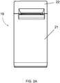
- the retail scale comprises a label printer 19 in order to print a label with the weight, the name of the article and the calculated price.
- Fig.1 schematically shows a control device 20 of the retail scale 11, which is integrated in the retail scale 11 and is designed to control the operation of the retail scale 11, in particular including the label printer 19.
- the label printer 19 is in Fig. 2A shown in a single view from the front.
- Fig. 2B a front cover of the label printer 19 in the form of a flap 21 and a separate cover section 22 is omitted, so that the interior of the label printer 19 can be seen.
- a holder 23 for a label roll and a deflection roller 25 is visible inside the label printer 19, a holder 23 for a label roll and a deflection roller 25 is visible.
- a print head and a print roller of the label printer 19, however, are in Fig. 2B not visible.
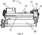
- the label printer 19 can be operated in particular with self-adhesive carrier-free endless tape labels. Therefore, the label printer 19 has a cutter 27 (which in Fig. 2B partially covered by a cover plate 28), with which the labels are separated from the endless belt. As can be seen from Fig.3 The cutter 27 comprises a driven transport roller 29 for the endless band labels, which can be rotated about a rotation axis. In addition, a knife unit 31 is provided, which has a knife carriage 33 (cf. Fig. 4A to 6B ), which can be moved linearly parallel to the axis of rotation of the transport roller 29, and a plate-shaped cutting knife 34 which is held in a rotationally fixed manner on the knife carriage 33 and is directed in the direction of the transport roller 29.
- the label printer 19 can, however, in principle also be operated with receipt paper.
- the knife carriage 33 is designed as a spindle nut with a passage 35 with an internal thread, which is driven by an electric motor 39 via a threaded rod 37, with which it forms a threaded spindle, in both axial directions of the threaded rod 37.
- the cutter 27 also comprises a straight guide running parallel to the threaded rod 37, which is designed as a guide rod 41 with a round cross section that extends through an opening 43 formed in the knife carriage 33.
- the opening 43 has a cross section in the shape of an elongated hole, so that tolerances in the distance between the threaded rod 37 and the guide rod 41 can be compensated.
- the self-adhesive, carrier-free endless band labels are guided between the transport roller 29 and the knife unit 31, with the adhesive-coated side of the endless band labels facing the transport roller 29, which acts as a counter-holder for the knife unit 31, in particular the cutting knife 34 of the knife unit 31.
- the two opposing directions of travel of the knife carriage 33 run perpendicular to the transport direction of the endless band labels.
- the print head and the print roller are in the Fig. 2B and 3 arranged behind or below the transport roller 29 and thus - as already mentioned above - not visible in the figures.
- the knife carriage 33 has a base body 45 and a plate-shaped extension 47 which projects from the base body 45 in the direction of the transport roller 29 and on which the cutting knife 34 is held by means of a plate-shaped knife holder 49 of the knife unit 31.
- the cutting knife 34 is arranged between the extension 47 and the knife holder 49.
- the extension 47, the cutting knife 34 and the knife holder 49 are arranged with their flat sides resting against one another. The flat sides of these components are thus oriented parallel to the plane of movement of the cutting knife 34 when the knife carriage 33 is moved.
- the passage 35 for the threaded rod 37 and the opening 43 for the guide rod 41 are each provided in the base body 45.
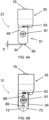
- the knife holder 49 and the cutting knife 34 form a structural unit 51 (see the Fig. 5A, 5B , 6B and 7 ), which is slidably attached to the extension 47 of the knife carriage 33 (see the respective double arrow in the Fig. 5A and 8A ), which is moved by a spring device 53 in the form of a compression spring into an extended position (cf. Fig. 8A ) and which, when the knife unit 31 is placed on endless band labels 55 running between the transport roller 29 and the knife unit 31, is pressed back into a retracted position against the spring force of the spring device 53 (cf. Fig. 8B ).
- the spring device 53 is supported with one end on the base body 45 and with the other end on the structural unit 51, namely on both the knife holder 49 and the cutting knife 34.
- the spring-loaded mounting of the cutting blade 34 or the assembly 51 has the advantage that the cutting blade 34 or the tip of the cutting blade 34 does not, or at least hardly, penetrate the surface of the transport roller 29 when a label is cut off, but is pushed back from the extended position by a distance determined by the spacing between the blade unit 31 and the transport roller 29. This can prevent the surface of the transport roller 29 from becoming roughened by continuous cutting. A surface roughened in this way would result in the endless band labels sticking more strongly to the transport roller 29 with their adhesive-coated side over time, which would disrupt the smooth transport of the endless band labels.
- the cutting knife 34 protrudes with a defined projection d over the knife holder 49, in particular an end surface 56 of the knife holder 49 facing the transport roller 29.
- the depth of penetration of the cutting knife 34 into the endless belt labels therefore always remains the same. This also applies in the case of tolerance-related unevenness in the surface of the transport roller 29.
- the projection d is adapted to the thickness of the labels and selected such that the labels can be safely separated from the endless belt.
- the projection can have a value of between 0.1 mm and 0.8 mm, preferably between 0.2 mm and 0.3 mm.
- the knife unit 31 is preferably aligned such that the cutting knife 34 or the tip of the cutting knife 34 when the knife carriage 33 is moved along a path which is parallel to the cutting knife 34 or the tip of the cutting knife 34 closest surface line of the transport roller 29. In principle, however, it is also possible for the cutting knife 34 or the tip of the cutting knife 34 to run along a surface line of the transport roller 29 when the knife carriage 33 moves, which has a predetermined offset to the closest surface line.
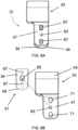
- the movable fastening of the structural unit 51 comprising the knife holder 49 and the cutting knife 34 is ensured by an elongated hole arrangement.
- an elongated hole 57, 59 is formed in the knife holder 49 and the cutting knife 34, which are arranged congruently with one another and through which a fastening screw 61 extends, so that the structural unit 51 can be moved along the two elongated holes 57, 59.
- the fastening screw 61 is screwed into a fastening hole 63 formed in the extension 47 of the knife carriage 33.
- the structural unit 51 is accommodated in the axial direction of the fastening screw 61 with play between the head of the fastening screw 61 and the extension 47.
- the play is achieved by providing a spacer sleeve 65, the extent of which in the axial direction of the fastening screw 61 is greater than the corresponding extent of the structural unit 51 and through which the shaft of the fastening screw 61 is inserted so that the spacer sleeve 65 also extends through the two elongated holes 57, 59.
- the head of the fastening screw 61 is on the spacer sleeve 65 at one axial end and the extension 47 of the knife carriage 33 is on the other axial end.
- the knife holder 49 and the cutting knife 34 are plugged together to form the structural unit 51.
- the knife holder 49 has two pins 67 protruding in the direction of the cutting knife 34, which engage in corresponding openings 69 formed in the cutting knife 34. These two plug connections are opposite one another with respect to the fastening screw 61 or the spacer sleeve 65.
- the two pins 67 of the knife holder 49 extend through the two openings 69 formed in the cutting knife 34 and each engage in a corresponding elongated hole 71 formed in the extension 47. This can reliably prevent the structural unit 51 from rotating about the longitudinal axis of the fastening screw 61 or the spacer sleeve 65.
- the knife carriage 33 is between a first end position to the right of the transport roller 29 (cf. Fig. 8A ) and an analogous second end position to the left of the transport roller 29 (not shown) and can cut off labels in both directions of travel.
- the cutting knife 34 has a cutting edge 73 on the leading edge in both directions of travel of the knife carriage 33.
- the two cutting edges 73 together form a V-shape in the plane of movement of the cutting knife 34 when the knife carriage 33 is moved, whereby a particularly good cutting result can be achieved.
- the endless band labels 55 are transported step by step by a motor, one label at a time.
- a label is first printed, then the endless band labels are transported one label at a time and then the knife unit 31 or the knife carriage 33 is moved between a start position which corresponds to the aforementioned first end position of the knife carriage 33 (cf. Fig. 8A ), and a target position as shown in Fig.9 shown, proceed linearly.
- the cutting knife 34 is located to the left of the left edge of the endless band labels 55, ie the label to be separated has been completely separated.
- the separated label is placed in the target position according to Fig.9 held by the knife unit 31 on the transport roller 29 and can then be removed by an operator.
- Holding the severed label in the target position of the knife unit 31 is achieved in that the endless belt labels 55 rest with their underside on the transport roller 29 and are clamped between the end surface 56 of the knife holder 49, which lies in the direction of the transport roller 29 and rests on the top side of the endless belt labels 55, and the transport roller 29 when the knife unit 31 is moved from the start position to the target position. This then applies in particular to the severed label in the target position of the knife unit 31.
- the knife unit 31 or the knife carriage 33 is not moved completely into the aforementioned second end position, but only to the extent that the end surface 56 of the knife holder 49 with a trailing section is still in the area of the endless belt labels 55 or the severed label.
- the cutting knife 34 slides on the surface of the transport roller 29.
- the end face 56 of the knife holder 49 runs along a surface line of the transport roller 29 that is closest to the end face 56 of the knife holder 49, since this allows the severed label to be held particularly well.
- the cutting knife 34 or the tip of the cutting knife 34 then runs along a surface line of the transport roller 29 that is offset from this, in particular slightly.
- the system waits until the separated label is removed by an operator.
- a detector device (not shown) is provided, which detects whether the separated label has been removed by an operator. Only when this is the case does the blade unit 31 automatically move out of the target position. The blade unit 31 can either move back to the start position or move on to a further start position beyond the target position, which corresponds to the aforementioned second end position, and the endless band labels 55 can be removed before the next label is printed, which has already been has partially passed through the printing area, it must be retracted to the beginning of the label where the label was separated (reversing). The process steps described above are then repeated for the next label to be separated.
- the blade unit 31 moves in the opposite direction to cut off the next label, ie in the direction of the starting position, to a further target position (not shown) which corresponds to the Fig.9 shown position, but on the right edge of the endless band labels 55.
- the knife unit 31 is therefore not moved back completely to the first end position, but only so far that the end surface 56 of the knife holder 49 with a trailing section is still in the area of the endless band labels 55, so that the next separated label is also held on the transport roller 29. After the next label has been removed, the knife unit 31 then moves back completely to the start position.
- the knife unit 31 In order to calibrate the starting position of the knife unit 31, a reference run of the knife unit 31 is carried out when the label printer 19 is switched on.
- the knife unit 31 is provided with a magnet 75 which interacts with a stationary magnetic field sensor 77, in particular a Hall sensor, which detects the passing magnet 75 (cf. Fig.3 ).
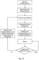
- FIG.10 A flow chart illustrating the process steps described above is shown in Fig.10 shown, wherein the method steps are controlled or executed by the control device 20.
- the alternative method can also be carried out with carrier tape labels, in which the labels are applied to a carrier tape.
- Fig. 11 an alternative knife unit 31 to the knife unit 31 explained in the previous figures is shown.
- the knife unit 31 according to Fig. 11 the spacer sleeve 65 not only through the structural unit 51, but also through the extension 47 of the knife carriage 33.
- the spacer sleeve 65 of the knife unit 31 is in accordance with Fig. 11 with the other axial end not on the side of the extension 47 facing the structural unit 51, but with a flange 79 formed on this end on the opposite side of the extension 47.
- the fastening screw 61 of the knife unit is according to Fig. 11 not screwed into the extension 47, but into the spacer sleeve 65.
- the extension of the spacer sleeve 65 in the axial direction of the fastening screw 61 is greater than the combined extension of the structural unit 51 and extension 47 of the knife carriage 33.
- the alternative knife unit 31 according to Fig. 11 has the advantage that no fastening hole with an internal thread is required in the extension 47. This is particularly advantageous if the knife carriage 33 with the extension 47 is made of a plastic. For the same reason, the knife unit 31 according to Fig. 11 an insert sleeve 81 is also provided in the passage 35.
- the spacer sleeve 65 and the insert sleeve 81 can be made of a metal that can easily be provided with an internal thread for the fastening screw 61 or for the threaded rod 37.
- the alternative knife unit 31 according to Fig. 11 The two elongated holes 71 are designed as countersunk holes, but can just as well be designed as continuous elongated holes.
Landscapes
- Life Sciences & Earth Sciences (AREA)
- Forests & Forestry (AREA)
- Engineering & Computer Science (AREA)
- Mechanical Engineering (AREA)
- Handling Of Sheets (AREA)
- Labeling Devices (AREA)
Priority Applications (1)
| Application Number | Priority Date | Filing Date | Title |
|---|---|---|---|
| EP24192838.1A EP4434697A3 (fr) | 2020-07-10 | 2020-07-10 | Dispositif de coupe pour étiquettes autocollantes sans bande sans support |
Applications Claiming Priority (2)
| Application Number | Priority Date | Filing Date | Title |
|---|---|---|---|
| EP20185212.6A EP3936288B1 (fr) | 2020-07-10 | 2020-07-10 | Dispositif de découpe pour étiquettes à bande continue sans support auto-adhésives |
| EP24192838.1A EP4434697A3 (fr) | 2020-07-10 | 2020-07-10 | Dispositif de coupe pour étiquettes autocollantes sans bande sans support |
Related Parent Applications (2)
| Application Number | Title | Priority Date | Filing Date |
|---|---|---|---|
| EP20185212.6A Division EP3936288B1 (fr) | 2020-07-10 | 2020-07-10 | Dispositif de découpe pour étiquettes à bande continue sans support auto-adhésives |
| EP20185212.6A Division-Into EP3936288B1 (fr) | 2020-07-10 | 2020-07-10 | Dispositif de découpe pour étiquettes à bande continue sans support auto-adhésives |
Publications (2)
| Publication Number | Publication Date |
|---|---|
| EP4434697A2 true EP4434697A2 (fr) | 2024-09-25 |
| EP4434697A3 EP4434697A3 (fr) | 2024-11-20 |
Family
ID=71786718
Family Applications (4)
| Application Number | Title | Priority Date | Filing Date |
|---|---|---|---|
| EP24192838.1A Pending EP4434697A3 (fr) | 2020-07-10 | 2020-07-10 | Dispositif de coupe pour étiquettes autocollantes sans bande sans support |
| EP24192839.9A Pending EP4434698A3 (fr) | 2020-07-10 | 2020-07-10 | Dispositif de coupe pour étiquettes autocollantes sans bande sans support |
| EP20185212.6A Active EP3936288B1 (fr) | 2020-07-10 | 2020-07-10 | Dispositif de découpe pour étiquettes à bande continue sans support auto-adhésives |
| EP24192840.7A Pending EP4434699A3 (fr) | 2020-07-10 | 2020-07-10 | Dispositif de coupe pour étiquettes autocollantes sans bande sans support |
Family Applications After (3)
| Application Number | Title | Priority Date | Filing Date |
|---|---|---|---|
| EP24192839.9A Pending EP4434698A3 (fr) | 2020-07-10 | 2020-07-10 | Dispositif de coupe pour étiquettes autocollantes sans bande sans support |
| EP20185212.6A Active EP3936288B1 (fr) | 2020-07-10 | 2020-07-10 | Dispositif de découpe pour étiquettes à bande continue sans support auto-adhésives |
| EP24192840.7A Pending EP4434699A3 (fr) | 2020-07-10 | 2020-07-10 | Dispositif de coupe pour étiquettes autocollantes sans bande sans support |
Country Status (3)
| Country | Link |
|---|---|
| US (1) | US12129142B2 (fr) |
| EP (4) | EP4434697A3 (fr) |
| ES (1) | ES3000190T3 (fr) |
Families Citing this family (1)
| Publication number | Priority date | Publication date | Assignee | Title |
|---|---|---|---|---|
| CN116946510B (zh) * | 2023-08-14 | 2025-12-02 | 武汉库柏特科技有限公司 | 一种扁平状的输液袋全自动贴标签设备 |
Citations (1)
| Publication number | Priority date | Publication date | Assignee | Title |
|---|---|---|---|---|
| DE19958274A1 (de) | 1999-12-03 | 2001-06-21 | Hengstler Gmbh | Abschneider für klebende Etiketten |
Family Cites Families (23)
| Publication number | Priority date | Publication date | Assignee | Title |
|---|---|---|---|---|
| US791793A (en) * | 1903-10-09 | 1905-06-06 | Albert Johnson | Wall-paper cutter. |
| US4440055A (en) | 1981-12-31 | 1984-04-03 | Daniel Gelfand | Mat cutting device |
| US4535664A (en) * | 1982-09-07 | 1985-08-20 | Raymond Gary E | Dispenser means for rolled sheet materials |
| US4732069A (en) * | 1987-05-08 | 1988-03-22 | Gerber Scientific Products, Inc. | Knife and knife holder assembly |
| JPH0616699Y2 (ja) * | 1988-02-29 | 1994-05-02 | カール事務器株式会社 | 紙截断器のカッタ刃支持構造 |
| JP2796720B2 (ja) | 1988-09-16 | 1998-09-10 | エヌシーアール インターナショナル インコーポレイテッド | 記録紙切断装置 |
| US5611253A (en) | 1993-09-07 | 1997-03-18 | Tohoku Ricoh Co., Ltd. | Cutting device |
| US5442983A (en) | 1993-09-30 | 1995-08-22 | D'angelo; Joseph J. | All-electric web feeding, cutting and sheet dispensing machine |
| US5819618A (en) | 1994-05-10 | 1998-10-13 | Martin Yale Industries, Inc. | Rotary paper trimmer |
| JP2541151B2 (ja) | 1994-05-16 | 1996-10-09 | 日本電気株式会社 | 紙切断装置 |
| JP3619993B2 (ja) * | 2001-02-16 | 2005-02-16 | カール事務器株式会社 | カッターカセット及び裁断具 |
| JP2003316266A (ja) | 2002-04-22 | 2003-11-07 | Sii P & S Inc | 感熱性粘着シートの熱活性化装置およびプリンタ装置 |
| JP4543900B2 (ja) | 2004-01-27 | 2010-09-15 | ブラザー工業株式会社 | ラベルプリンタ |
| DE202004019430U1 (de) * | 2004-12-16 | 2005-03-10 | Wilhelm Bilstein KG Spezialfabrik für Maschinenmesser und Kompressorventile | Handschutz für Kreismesserhalter |
| US20070028463A1 (en) * | 2005-08-02 | 2007-02-08 | Chan Stephen K K | Paper cutter |
| WO2008124837A2 (fr) | 2007-04-10 | 2008-10-16 | Acco Brands Usa Llc | Massicot |
| US8763505B2 (en) * | 2009-03-16 | 2014-07-01 | Carl Manufacturing Co., Ltd. | Cutter |
| JP2014024283A (ja) | 2012-07-27 | 2014-02-06 | Ricoh Co Ltd | 画像形成装置及び画像形成方法 |
| EP3318412B1 (fr) | 2016-11-08 | 2019-10-16 | Mettler-Toledo (Albstadt) GmbH | Imprimante d'étiquettes pour étiquettes sans support |
| WO2018204397A1 (fr) * | 2017-05-01 | 2018-11-08 | Avery Dennison Retail Information Services, Llc | Combinaison d'imprimante et d'appareil de coupe |
| EP3505355B1 (fr) | 2017-12-31 | 2022-01-26 | Bizerba SE & Co. KG | Dispositif de découpage pour rouleaux étiquettes |
| CN112839824A (zh) | 2018-09-13 | 2021-05-25 | 艾利丹尼森零售信息服务公司 | 贴标机装置 |
| EP3936446B1 (fr) | 2020-07-10 | 2022-12-21 | Bizerba SE & Co. KG | Procédé de séparation d'étiquettes |
-
2020
- 2020-07-10 EP EP24192838.1A patent/EP4434697A3/fr active Pending
- 2020-07-10 ES ES20185212T patent/ES3000190T3/es active Active
- 2020-07-10 EP EP24192839.9A patent/EP4434698A3/fr active Pending
- 2020-07-10 EP EP20185212.6A patent/EP3936288B1/fr active Active
- 2020-07-10 EP EP24192840.7A patent/EP4434699A3/fr active Pending
-
2021
- 2021-07-08 US US17/370,652 patent/US12129142B2/en active Active
Patent Citations (1)
| Publication number | Priority date | Publication date | Assignee | Title |
|---|---|---|---|---|
| DE19958274A1 (de) | 1999-12-03 | 2001-06-21 | Hengstler Gmbh | Abschneider für klebende Etiketten |
Also Published As
| Publication number | Publication date |
|---|---|
| US12129142B2 (en) | 2024-10-29 |
| EP4434697A3 (fr) | 2024-11-20 |
| EP3936288A1 (fr) | 2022-01-12 |
| EP4434698A2 (fr) | 2024-09-25 |
| EP3936288B1 (fr) | 2024-09-11 |
| EP4434699A3 (fr) | 2024-11-27 |
| EP4434699A2 (fr) | 2024-09-25 |
| US20220009741A1 (en) | 2022-01-13 |
| ES3000190T3 (en) | 2025-02-27 |
| EP4434698A3 (fr) | 2025-01-01 |
Similar Documents
| Publication | Publication Date | Title |
|---|---|---|
| EP1839768B1 (fr) | Presse à découper, en particulier destinée à tronçonner et à finir les extrémités de matériau plat pour ferrureries de fenêtre | |
| DE2457869C2 (de) | Setzgerät für Etikettenhalter | |
| EP0850697B1 (fr) | Dispositif pour l'application de matériaux fluides sur un substrat, en particulier pour l'application intermittente de colles fluides | |
| EP3936446B1 (fr) | Procédé de séparation d'étiquettes | |
| EP0360108B1 (fr) | Procédé et dispositif pour la distribution d'étiquettes | |
| DE69509871T2 (de) | Etikettiermaschine | |
| EP3936288B1 (fr) | Dispositif de découpe pour étiquettes à bande continue sans support auto-adhésives | |
| DE3434653A1 (de) | Stechwerkzeug | |
| EP1445082B1 (fr) | Encolleuse de chants | |
| DD202258A5 (de) | Vorrichtung zum einstanzen eines loches in eine papierbahn | |
| EP0756919B1 (fr) | Dispositif pour poinçonner un matériau en forme de bande ou feuille | |
| DE102014116972B4 (de) | Verfahren und Vorrichtung zum Einstellen eines Messerpakets eines Messerrings auf einen vorbestimmten Messervorstand | |
| DE3115530A1 (de) | "vorrichtung zum intermittierenden transportieren eines in regelmaessigen abstaenden mit hintereinander angeordneten steuerausnehmungen versehenen bandes" | |
| DE4332803C2 (de) | Vorrichtung zum automatischen Zuführen von Druckplatten zum Plattenzylinder einer Druckmaschine | |
| DE9116211U1 (de) | Vorrichtung zum schneidenden Erzeugen eines dünnen Brettes | |
| DE4220181A1 (de) | Vorschubeinrichtung, insbesondere Klebebandspender | |
| DE3308753C2 (de) | Vorrichtung zum Abziehen einer Oberflächenschicht von Drähten aus Kunststoffen, insbesondere Thermoplasten wie Polyäthylen und Polypropylen | |
| EP4368359B1 (fr) | Agencement de poinçonnage et procédé de fonctionnement dumême | |
| BE1032574B1 (de) | Vorrichtung zum Schneiden eines Schnittmaterials | |
| DE10123523A1 (de) | Verfahren und Vorrichtung zum Anhaften eines streifenförmigen Deckmaterials an Werkstückoberflächen von fortlaufend bewegten platten- oder leistenförmigen Werkstücken | |
| DE10351877A1 (de) | Schneidvorrichtung zum Abtrennen von Etiketten und Verfahren zum Abtrennen von Etiketten | |
| EP3192637A1 (fr) | Système de coupe | |
| DE102006058574A1 (de) | Klebebandhalter einer Linearvorrichtung | |
| DE10119138B4 (de) | Austauschbares Umlenkelement, Falztasche und Falzmaschine | |
| DE1728327C3 (de) | Vorrichtung zum Anbringen von C-förmigen, im einen Arm ein Gewinde aufweisenden Metallfederklammern an einer mit einem Loch versehenen Platte |
Legal Events
| Date | Code | Title | Description |
|---|---|---|---|
| PUAI | Public reference made under article 153(3) epc to a published international application that has entered the european phase |
Free format text: ORIGINAL CODE: 0009012 |
|
| STAA | Information on the status of an ep patent application or granted ep patent |
Free format text: STATUS: THE APPLICATION HAS BEEN PUBLISHED |
|
| AC | Divisional application: reference to earlier application |
Ref document number: 3936288 Country of ref document: EP Kind code of ref document: P |
|
| AK | Designated contracting states |
Kind code of ref document: A2 Designated state(s): AL AT BE BG CH CY CZ DE DK EE ES FI FR GB GR HR HU IE IS IT LI LT LU LV MC MK MT NL NO PL PT RO RS SE SI SK SM TR |
|
| REG | Reference to a national code |
Ref country code: DE Ref legal event code: R079 Free format text: PREVIOUS MAIN CLASS: B26D0007260000 Ipc: B26D0001060000 |
|
| PUAL | Search report despatched |
Free format text: ORIGINAL CODE: 0009013 |
|
| AK | Designated contracting states |
Kind code of ref document: A3 Designated state(s): AL AT BE BG CH CY CZ DE DK EE ES FI FR GB GR HR HU IE IS IT LI LT LU LV MC MK MT NL NO PL PT RO RS SE SI SK SM TR |
|
| RIC1 | Information provided on ipc code assigned before grant |
Ipc: B26D 7/26 20060101ALI20241017BHEP Ipc: B26D 1/06 20060101AFI20241017BHEP |
|
| STAA | Information on the status of an ep patent application or granted ep patent |
Free format text: STATUS: REQUEST FOR EXAMINATION WAS MADE |
|
| 17P | Request for examination filed |
Effective date: 20250520 |