EP1445082B1 - Encolleuse de chants - Google Patents
Encolleuse de chants Download PDFInfo
- Publication number
- EP1445082B1 EP1445082B1 EP04002099A EP04002099A EP1445082B1 EP 1445082 B1 EP1445082 B1 EP 1445082B1 EP 04002099 A EP04002099 A EP 04002099A EP 04002099 A EP04002099 A EP 04002099A EP 1445082 B1 EP1445082 B1 EP 1445082B1
- Authority
- EP
- European Patent Office
- Prior art keywords
- edge
- workpiece
- glueing
- glueing device
- carrier
- Prior art date
- Legal status (The legal status is an assumption and is not a legal conclusion. Google has not performed a legal analysis and makes no representation as to the accuracy of the status listed.)
- Expired - Lifetime
Links
- 238000004026 adhesive bonding Methods 0.000 claims abstract description 34
- 238000003825 pressing Methods 0.000 claims abstract description 4
- 239000003292 glue Substances 0.000 claims abstract 2
- 239000012790 adhesive layer Substances 0.000 claims description 8
- 230000003213 activating effect Effects 0.000 claims description 3
- 238000003801 milling Methods 0.000 description 12
- 239000004831 Hot glue Substances 0.000 description 7
- XEEYBQQBJWHFJM-UHFFFAOYSA-N Iron Chemical compound [Fe] XEEYBQQBJWHFJM-UHFFFAOYSA-N 0.000 description 6
- 229910052742 iron Inorganic materials 0.000 description 3
- 229920000877 Melamine resin Polymers 0.000 description 2
- 230000001154 acute effect Effects 0.000 description 2
- 239000000853 adhesive Substances 0.000 description 2
- 230000001070 adhesive effect Effects 0.000 description 2
- 150000001875 compounds Chemical class 0.000 description 2
- 239000010410 layer Substances 0.000 description 2
- JDSHMPZPIAZGSV-UHFFFAOYSA-N melamine Chemical compound NC1=NC(N)=NC(N)=N1 JDSHMPZPIAZGSV-UHFFFAOYSA-N 0.000 description 2
- 239000002184 metal Substances 0.000 description 2
- 229910052751 metal Inorganic materials 0.000 description 2
- 239000007787 solid Substances 0.000 description 2
- 238000010073 coating (rubber) Methods 0.000 description 1
- 230000001419 dependent effect Effects 0.000 description 1
- 238000012423 maintenance Methods 0.000 description 1
- 238000000034 method Methods 0.000 description 1
- 230000001360 synchronised effect Effects 0.000 description 1
- 239000002023 wood Substances 0.000 description 1
Images
Classifications
-
- B—PERFORMING OPERATIONS; TRANSPORTING
- B29—WORKING OF PLASTICS; WORKING OF SUBSTANCES IN A PLASTIC STATE IN GENERAL
- B29C—SHAPING OR JOINING OF PLASTICS; SHAPING OF MATERIAL IN A PLASTIC STATE, NOT OTHERWISE PROVIDED FOR; AFTER-TREATMENT OF THE SHAPED PRODUCTS, e.g. REPAIRING
- B29C63/00—Lining or sheathing, i.e. applying preformed layers or sheathings of plastics; Apparatus therefor
- B29C63/0026—Lining or sheathing, i.e. applying preformed layers or sheathings of plastics; Apparatus therefor an edge face with strip material, e.g. a panel edge
- B29C63/003—Lining or sheathing, i.e. applying preformed layers or sheathings of plastics; Apparatus therefor an edge face with strip material, e.g. a panel edge continuously
-
- B—PERFORMING OPERATIONS; TRANSPORTING
- B27—WORKING OR PRESERVING WOOD OR SIMILAR MATERIAL; NAILING OR STAPLING MACHINES IN GENERAL
- B27D—WORKING VENEER OR PLYWOOD
- B27D5/00—Other working of veneer or plywood specially adapted to veneer or plywood
- B27D5/003—Other working of veneer or plywood specially adapted to veneer or plywood securing a veneer strip to a panel edge
Definitions
- the present invention relates to a Kantenanleimvortechnische for applying a Umleimers on an edge of a workpiece, according to the preamble of claim 1.
- Devices for applying a edge band to an edge of a workpiece, in particular a wooden workpiece are known in different embodiments.
- These so-called Kantenanleimvorraumen be used in woodworking to apply veneer strip (lipping) on an edge of a workpiece.
- Machine-driven special machines with their own underframe and their own stop are often used for this purpose, which are only suitable for applying edge banding to workpiece edges. These special machines are relatively expensive, but provide good results in terms of the accuracy of fit of the edge band on the edge of the workpiece.
- the edge band is often applied by means of an iron or the like on an edge of a workpiece. This is usually lipping used, the one-sided with a activatable hot melt adhesive is provided. The edge band is cut to fit the edge length of the workpiece to be machined, placed on the edge of the workpiece, fixed by activating the hot melt adhesive by means of the iron on the edge and, if necessary, manually reworked.
- this method often provides in terms of fit accuracy of the edge only insufficient results.
- EP 0 728 561 A1 is an edge banding device for releasable attachment to a spindle of a machine tool known, but does not have a continuous supply of Umleimers.
- the object of the invention is to provide an inexpensive and flexibly applicable edge banding device which is easy to operate and, moreover, ensures a high accuracy of fit of the edge band on the edge of the workpiece.
- a Kantenanleimvorraum of the aforementioned type wherein the Kantenanleimvorraum has at least a first feed roller, which is in the feed direction with the edge during the feed of the workpiece in operative connection, and a second feed roller, with the first feed roller and the Umleimerzucht nails is operatively connected, wherein the feed of the workpiece causes the supply of the edge band in the Umleimerzuschreib sensible.
- the Kantenanleimvortechnisch can be releasably attached to the base of an existing in woodworking machine tool, which has a spindle.
- the machine tool can be, for example, a milling machine or a lathe, which, in addition to the spindle already mentioned, have a base frame and a stop on which the workpiece to be machined can be applied and securely guided.
- the term "spindle" has been chosen here for reasons of linguistic simplicity. It should be emphasized at this point that it does not depend in the present invention on a rotation of the spindle. The spindle is merely for the purpose of releasably attaching the carrier of the edge banding device to it.
- the spindle can therefore also another functionally identical Element (for example, arranged on a frame cylinder or cuboid-like element) can be used to which the support of the Kantenanleimvor Nobel can be releasably attached.
- the solution according to the invention has the advantage that no expensive special machine with its own base frame and its own stop must be purchased, which is only suitable for applying a edge band to a workpiece edge. Instead, the frame, the spindle, the stop and possibly the feed of an existing machine tool are used, wherein the carrier of Kantenanleimvoroplasty invention is releasably attached to the tool spindle and thus relatively quickly removed from the spindle.
- edge banding device With the edge banding device according to the invention, furthermore, significantly better results can be achieved with respect to the accuracy of fit of the edge band on the edge of the workpiece than with the use of an iron or the like.
- the means for releasably attaching the Kantenanleimvor substances comprise a carrier arranged in the receptacle, which is positively placed on the spindle.
- this embodiment permits a simple and quick attachment of the edge banding device to the spindle of the machine tool. If the edge banding device is to be placed, for example, on the spindle of a milling machine, first the milling head of the milling machine is dismantled, thereby releasing the spindle. Subsequently, the recording of the carrier is placed on the spindle.
- a particularly preferred embodiment of the present invention provides that the receptacle is substantially circular. This ensures that the recording is easy, quick and convenient to the spindle of the machine tool can be placed.
- the receptacle comprises an adapter which is adapted to the shape and the diameter of the spindle.
- the Kantenanleimvorraum is versatile, because for different types of machine tools With differently executed spindles, only the adapter needs to be replaced in order to be able to releasably attach the carrier of the edge banding device to the spindle of the machine tool.
- the edge banding device comprises at least one locking device in order to attach the carrier to the spindle and / or the stop of the machine tool so as to be displaceable and / or non-rotatable.
- This locking device ensures that the KantenanleimvorATP is securely attached to the spindle during its operation, whereby the handling of the Kantenanleimvoroplasty is facilitated and better results are achieved with respect to the accuracy of fit of Umleimers.
- a development of the present invention provides that the carrier is formed substantially plate-shaped. Above all, this embodiment facilitates the assembly of the edge banding device according to the invention, since the lateral plane defined by the plate-shaped support runs substantially perpendicular to the edge of the workpiece to which the edge band is to be applied.
- the edge banding device comprises a hot air blower which is suitable for activating an adhesive layer applied to the edge band.
- the hot air blower is preferably arranged so that the outflowing hot air hits directly on the provided with the hot melt adhesive side of the edge band.
- a gluing device for applying an adhesive layer to the edge of the workpiece and / or the edge band may also be provided.
- This embodiment is advantageous if a lipping is to be used, which itself is not provided with an activatable adhesive layer.
- the edge banding device is preferably designed such that the hot air blower can be replaced by the gluing device.
- a workpiece rest can be used that is positionable at different angles to the edge banding device.
- the pressing device which presses the edge band to the edge of the workpiece
- the pressing device is designed as a pressure roller.
- the edge of the workpiece is pressed against the pinch roller, with a section of the edge band always being located between the workpiece edge and the pinch roller during the feed. It always acts a force component perpendicular to the feed direction in the direction of the pressure roller. This in turn exerts a counter force from the pinch roller on the edge band and the edge of the workpiece, whereby the adhesive connection between the edge band and the edge of the workpiece is produced.
- the pressure roller is rotatably mounted on the support of the Kantenanleimvorraum. This embodiment ensures that the edge band fed to the edge of the workpiece by means of the edge banding device is aligned parallel to this edge, so that the tailor-made application of the edge band to the edge of the workpiece is improved.
- the lapping feeder device comprises at least one guide rail into which the lipping is received and fed during feed of the workpiece in the feed direction by train the edge of the workpiece.
- This guide rail is preferably made of metal, which has proven to be advantageous in terms of longevity of Umleimerzubow Road.
- the at least one guide rail of the stripper supply device can be adapted to the width of the edge band. This ensures that the Kantenanleimvorraum can be used very flexible.
- the edge feeder of the edge banding device can be adapted to the edge band to be used.
- the at least one guide rail of the stripper feed device has a plurality of guide rollers.
- edge band has a cutting device with the aid of which the edge band along its width, i. transverse to the feed direction, can be severed to complete the edge of the workpiece with the edge band substantially flush.
- this cutting device is manually operable.
- an operating lever may be provided, which enables a needs-based operation of the cutting device and thus the transection of the edge band along its width.
- the edge banding device has an upper part which can be detachably fastened to the carrier.
- This upper part serves to cover all elements of the edge banding device and, in particular for reasons of maintenance, is detachably fastened to the carrier.
- the edge band inside the stripper feed device has been transported exclusively by a tensile force acting during the feed of the workpiece. Under certain circumstances, this tensile force can lead to a tearing of the edge band inside the stripper feed device. Therefore, in order to improve the continuous supply of the edge band, a particularly preferred embodiment provides that the edge banding device has at least one first feed roller, which is in operative connection with the edge during the feed of the workpiece in the feed direction, and a second feed roller which is connected to the first feed roller and the edge strip feeder is in operative connection, wherein the advancement of the workpiece causes the supply of the edge band in the stripper feed device.
- the active compounds are produced by frictional engagement, it is advantageous to carry out the feed rollers as solid rubber rollers or at least to provide rollers with an outer rubber coating.
- knurled rolls for example a knurled metal second feed roll
- the diameters of the first feed roller and the second feed roller are selected so that the supply of the edge band takes place synchronously with the movement of the workpiece in the feed direction. This embodiment considerably simplifies the operation of the edge banding device, since the edge band is always fed in synchronism with the advancing movement of the workpiece.
- an advantageous embodiment provides that a guide roller is rotatably arranged in the manner on the carrier, that it faces the second feed roller, and that a portion of the stripper feeding between the second feed roller and the guide roller extends.
- this guide roller is made of solid rubber or at least provided with an outer rubber layer in order to optimize the friction-based operative connection with the Umleimerzubow vibration.
- an edge banding apparatus is provided with the present invention, which is flexibly placed on the spindle of a machine tool, with no additional drive means are required to supply the edge band of the edge of the workpiece continuously.
- Another advantage of the present invention is that the base frame and the fence of the machine tool can be used to guide the workpiece along the edge banding device.
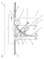
- FIG. 1 Figure 4 is a schematic plan view of an edge banding apparatus 1 for applying a banding 4 to an edge 6 of a workpiece 5 in accordance with a preferred embodiment of the present invention.
- the edge banding device 1 has a carrier 2, which in this exemplary embodiment has a substantially plate-shaped design.
- a Umleimerzuschreib issued 7 for the continuous supply of Umleimers 4 a first feed roller 8a, a second feed roller 8b, a guide roller 8c, a pinch roller 9, a hot air blower 10 and a cutter 11 are arranged.
- the first feed roller 8a, the second feed roller 8b, the guide roller 8c and the pinch roller 9 are each rotatably supported.
- the Kantenanleimvoroplasty invention 1 comprises a not explicitly shown in this view upper part 3, which is placed on the carrier 2 and can be releasably attached thereto.
- this upper part 3 is designed to be height adjustable with respect to the carrier 2.
- the stripper feed device 7 comprises a guide rail (not shown in detail here) along which the edge strip 4 is guided in the feed direction.
- a lipping 4 for example, colored and optionally grained melamine paper is used which has on one side an activatable, preferably provided with a conventional hot melt adhesive layer. It can also ABS edges, real wood edges or the like can be used.
- the carrier 2 of the edge banding device 1 comprises a substantially circular receiver 12, which is suitable for The edge banding device according to the invention, for example, set up on an approximately cylindrical spindle 13 of a machine tool or the like.
- edge banding device 1 is to be attached, for example, to the spindle 13 of a milling device, first the milling head of the milling device is removed, so that the spindle 13 becomes accessible. Then the Kantenanleimvoruze 1 is placed with its receptacle 12 on the spindle 13.
- locking means may be provided in order to attach the Kantenanleimvorides 1 with the receptacle 12 releasably but displaceable and / or against rotation on the spindle 13 and the stopper 14.
- the position and the shape of the receptacle 12 is dependent on the shape and / or the position of the spindle 13.
- the receptacle 12 can be arranged slidably in the longitudinal and / or transverse direction on the carrier 2 and beyond adapters for different diameters and Shapes of the spindle 13 may be provided to allow the most flexible use of Kantenanleimvoroplasty invention 1.
- the detachable attachment of Kantenanleimvor therapies 1 to a spindle 13 of a milling device or the like has the advantage that the Kantenanleimvoruze 1 easily, quickly and easily placed on the spindle 13 of a milling device and removed from this again and can be exchanged for the milling head. So can be changed in practice relatively quickly between the steps milling and applying the edge band.
- the solution according to the invention also has the advantage that, for example, a commonly used in a milling device support frame and a stop and a feed for guiding a workpiece can be used to secure the workpiece to be machined 5 in the Fig.1 indicated by an arrow feed direction with the edge 6 on the Kantenanleimvorraum 1 along.
- a commonly used in a milling device support frame and a stop and a feed for guiding a workpiece can be used to secure the workpiece to be machined 5 in the Fig.1 indicated by an arrow feed direction with the edge 6 on the Kantenanleimvorraum 1 along.
- no separate special machine with its own frame, stop and feed for applying the edge band 4 on a workpiece 5 must be purchased.
- the stripper feeding device 7 is designed such that it feeds the edge strip 4 of the edge 6 at an acute angle relative to the feed direction of the workpiece 5.
- the stripper feed device 7 can additionally have a plurality of rotatably mounted rollers, which are not explicitly shown here. These rollers facilitate the continuous supply of the edge band 4 in comparison to a stripper feeding device 7 which has no additional rollers.
- a first feed roller 8a is initially provided in the feed direction and is operatively connected to the edge 6 of the workpiece 5 and a second feed roller 8b.
- the active compound is preferably produced by friction.
- the diameter of the first feed roller 8a is here chosen smaller than that of the second feed roller 8b.
- the second feed roller 8b in turn is in operative connection with the edge 4 within the edge feeder 7.
- the first feed roller 8a experiences, based on the operative connection between it and the edge 6, a relation to the illustration in FIG Fig. 1 clockwise rotation. Due to the operative connection with the second feed roller 8b, the latter in turn rotates counterclockwise and provides an operative connection with the edge band 4 in the stripper feed device 7 for its continuous feed in the transport direction. Accordingly, the diameters of the first feed roller 8a and the second feed roller 8b are selected such that the ratio of the diameters enables a continuous feed of the edge band 4 which is substantially synchronous with the advance of the workpiece 5.
- an additional guide roller 8c is provided, which is arranged opposite to the second feed roller 8b in such a manner that the edge feeder 7 runs in sections between the second feed roller 8b and the guide roller 8c.
- the guide roller 8c ensures safe guidance of the edge band 4 in the stripper feed device 7.
- the movement of the workpiece 5 in the feed direction is thus converted via the roller arrangement just described into a transport movement of the edge band 4 in the stripper feeding device 7.
- a hot air blower 10 is arranged in such a way that the hot air flowing out of the hot air blower 10 is directed substantially onto the side of the edge band 4 provided with the adhesive layer.
- This adhesive layer is usually hot melt adhesive, which is activated by supplying heat at a certain temperature, so that the edge 4 can adhere to the edge 6 of the workpiece 5.
- the hot air blower 10 it is also possible to provide a gluing device which either provides an edge band 4 not provided with a hotmelt adhesive or the edge 6 of the workpiece 5 with an adhesive layer. For this reason, it is advantageous to design the edge banding device 1 such that the hot air blower 10 can be easily and quickly replaced by a gluing device.
- the edge stripper 7 is arranged at an acute angle relative to the feed direction of the workpiece 5. Further, viewed in the feed direction behind the hot air blower 10, a pinch roller 9 is provided which is formed so that the edge 4 is bent in the feed direction in such a way that it is aligned substantially parallel to the edge 6 of the workpiece 5. During manual or mechanical advancement of the workpiece 5, a force component always acts perpendicular to the feed direction in the direction of the edge banding device 1. As a result, a contact pressure is generated between the edge 6 of the workpiece 5, the edge strip 4 and the pressure roller 9 to form an adhesive bond between the edge 6 and make the edge 4.
- the first feed roller 8a, the second feed roller 8b and the guide roller 8c can be dispensed with a corresponding design of the Umleimerzucht Nur 7 on the first feed roller.
- the force acting during the feed between the edge 6 of the workpiece 5, the edge 4 and the pressure roller 9 contact pressure ensures that during movement of the workpiece 5 in the feed direction of the edge band 4 is pulled continuously from the Umleimerzucht Anlagen 7 and is adhesively connected to the edge 6.
- a manually operable cutting device 11 which is pivotably articulated about an axis of rotation, is also provided.
- a cutting surface of the cutting device 11 is arranged so that it cuts through the edge strip 4 approximately in a section between the second feed roller 8b and the hot air blower 10 transversely to the transport direction in a manual operation of an operating lever of the cutting device.
- the manual actuation of the cutting device 11 thus makes it possible to cut through the edge band 4 sufficiently accurately, so that the edge band 4 ends the edge 6 of the workpiece 5 substantially flush.
Claims (19)
- Encolleuse de chants (1) permettant l'application d'une bande de chant (4) sur un chant (6) d'une pièce usinée (5), comprenant un support (2) sur lequel sont agencés au moins un dispositif d'amenée de bande de chant (7) et un dispositif presseur qui presse la bande de chant (4) contre le chant (6) de la pièce usinée (5), le support (2) présentant des moyens pour l'application amovible de l'encolleuse de chants (1) au niveau d'une broche (13) d'une machine-outil ou similaire, caractérisée en ce que l'encolleuse de chants (1) présente au moins un premier rouleau d'avance (8a) qui est en liaison active avec le chant (6) pendant l'avancement de la pièce usinée (5) dans le sens d'avance et présente un deuxième rouleau d'avance (8b) qui est en liaison active avec le premier rouleau d'avance (8a) et le dispositif d'amenée de bande de chant (7), l'avancement de la pièce usinée (5) entraînant l'amenée de la bande de chant (4) dans le dispositif d'amenée de bande de chant (7).
- Encolleuse de chants (1) selon la revendication 1, caractérisée en ce que les moyens d'application amovible de l'encolleuse de chants (1) comprennent un logement (12) agencé dans le support (2) et pouvant être placé par complémentarité de forme sur la broche (13).
- Encolleuse de chants (1) selon la revendication 2, caractérisée en ce que le logement (12) est réalisé de manière essentiellement circulaire.
- Encolleuse de chants (1) selon l'une quelconque des revendications 2 ou 3, caractérisée en ce que le logement (12) comprend un adaptateur qui est adapté à la forme et au diamètre de la broche (13).
- Encolleuse de chants (1) selon l'une quelconque des revendications 1 à 4, caractérisée en ce que l'encolleuse de chants (1) comprend au moins un dispositif de verrouillage afin de monter le support (2) sans possibilité de déplacement et/ou de rotation au niveau de la broche (13) et/ou au niveau d'une butée (14) de la machine-outil.
- Encolleuse de chants (1) selon l'une quelconque des revendications 1 à 5, caractérisée en ce que le support (2) est réalisé essentiellement en forme de plaque.
- Encolleuse de chants (1) selon l'une quelconque des revendications 1 à 6, caractérisée en ce que l'encolleuse de chants (1) comprend une soufflante d'air chaud (10) qui est adaptée pour activer une couche adhésive appliquée sur la bande de chant (4).
- Encolleuse de chants (1) selon l'une quelconque des revendications 1 à 7, caractérisée en ce que l'encolleuse de chants (1) comprend un dispositif d'encollage pour l'application d'une couche adhésive sur le chant (6) de la pièce usinée (5) et/ou la bande de chant (4).
- Encolleuse de chants (1) selon l'une quelconque des revendications 1 à 8, caractérisée en ce que le dispositif presseur est réalisé sous forme de rouleau presseur (9).
- Encolleuse de chants (1) selon la revendication 9, caractérisée en ce que le rouleau presseur (9) est logé de manière rotative sur le support (2).
- Encolleuse de chants (1) selon l'une quelconque des revendications 1 à 10, caractérisée en ce que le dispositif d'amenée de bande de chant (7) présente au moins un rail de guidage pour guider la bande de chant (4).
- Encolleuse de chants (1) selon la revendication 11, caractérisée en ce que l'au moins un rail de guidage du dispositif d'amenée de bande de chant (7) peut être adapté à la largeur de la bande de chant (4).
- Encolleuse de chants (1) selon l'une quelconque des revendications 11 ou 12, caractérisée en ce que l'au moins un rail de guidage du dispositif d'amenée de bande de chant (7) présente une pluralité de rouleaux de guidage.
- Encolleuse de chants (1) selon l'une quelconque des revendications 1 à 13, caractérisée en ce que l'encolleuse de chants (1) présente un dispositif de coupe (11).
- Encolleuse de chants (1) selon la revendication 14, caractérisée en ce que le dispositif de coupe (11) peut être actionné manuellement.
- Encolleuse de chants (1) selon l'une quelconque des revendications 1 à 15, caractérisée en ce que l'encolleuse de chants (1) présente une partie supérieure (3) qui est montée de manière amovible au niveau du support (2).
- Encolleuse de chants (1) selon la revendication 16, caractérisée en ce que la distance verticale entre la partie supérieure (3) et le support (2) est réglable afin d'adapter l'encolleuse de chants (1) à différentes largeurs de la bande de chant (4).
- Encolleuse de chants (1) selon l'une quelconque des revendications précédentes, caractérisée en ce que les diamètres du premier rouleau d'avance (8a) et du deuxième rouleau d'avance (8b) sont sélectionnés de telle sorte que l'amenée de la bande de chant (4) est synchronisée avec le mouvement de la pièce usinée (5) dans le sens d'avance.
- Encolleuse de chants (1) selon la revendication 18, caractérisée en ce qu'un rouleau de guidage (8c) est agencé de façon rotative sur le support (2) de manière à faire face au deuxième rouleau d'avance (8b) et en ce qu'une section du dispositif d'amenée de bande de chant (7) s'étend entre le deuxième rouleau d'avance (8b) et le rouleau de guidage (8c).
Applications Claiming Priority (2)
| Application Number | Priority Date | Filing Date | Title |
|---|---|---|---|
| DE10305022A DE10305022A1 (de) | 2003-02-07 | 2003-02-07 | Kantenanleimvorrichtung |
| DE10305022 | 2003-02-07 |
Publications (3)
| Publication Number | Publication Date |
|---|---|
| EP1445082A2 EP1445082A2 (fr) | 2004-08-11 |
| EP1445082A3 EP1445082A3 (fr) | 2007-12-26 |
| EP1445082B1 true EP1445082B1 (fr) | 2011-10-12 |
Family
ID=32603192
Family Applications (1)
| Application Number | Title | Priority Date | Filing Date |
|---|---|---|---|
| EP04002099A Expired - Lifetime EP1445082B1 (fr) | 2003-02-07 | 2004-01-31 | Encolleuse de chants |
Country Status (3)
| Country | Link |
|---|---|
| EP (1) | EP1445082B1 (fr) |
| AT (1) | ATE528114T1 (fr) |
| DE (1) | DE10305022A1 (fr) |
Cited By (1)
| Publication number | Priority date | Publication date | Assignee | Title |
|---|---|---|---|---|
| WO2017123101A1 (fr) | 2016-01-15 | 2017-07-20 | Hyfuse Limited | Appareil et procédé d'encollage de bords |
Families Citing this family (11)
| Publication number | Priority date | Publication date | Assignee | Title |
|---|---|---|---|---|
| DE102005018885B3 (de) * | 2005-04-22 | 2007-01-04 | Homag Holzbearbeitungssysteme Ag | Bearbeitungszentrum |
| ES2459296T5 (es) † | 2009-04-22 | 2022-06-29 | Homag Holzbearbeitungssysteme Ag | Dispositivo y procedimiento para el recubrimiento de piezas de trabajo |
| DE202009016509U1 (de) * | 2009-12-04 | 2011-04-14 | Homag Holzbearbeitungssysteme Ag | 5-Achsbearbeitungszentrum mit Anleimaggregat |
| ITMO20110131A1 (it) * | 2011-05-24 | 2012-11-25 | Scm Group Spa | Macchina bordatrice |
| DE102011114763A1 (de) * | 2011-10-01 | 2013-04-04 | Ima Klessmann Gmbh Holzbearbeitungssysteme | Verfahren und Vorrichtung zur Anbringung eines Kantenbandabschnitts |
| ITPC20120009A1 (it) * | 2012-04-17 | 2013-10-18 | Samec S P A | Dispositivo per il trascinamento di un bordo in una macchina bordatrice |
| DE102014103725A1 (de) | 2014-03-19 | 2015-10-08 | Holz-Her Gmbh | Vorrichtung zum Fixieren eines Kantenmaterials |
| EP3031588B1 (fr) * | 2014-12-12 | 2021-09-15 | BIESSE S.p.A. | Procédé pour meuler des panneaux en bois à noyau creux |
| ITUA20163282A1 (it) * | 2016-05-09 | 2017-11-09 | Scm Group Spa | Dispositivo e metodo di bordatura |
| CN113211609B (zh) * | 2021-04-02 | 2022-12-23 | 北新建材(天津)有限公司 | 一种连续式自动封边装置及其方法 |
| DE102021124866B3 (de) | 2021-09-27 | 2022-10-20 | Ima Schelling Deutschland Gmbh | Trennvorrichtung, Kantenbearbeitungsvorrichtung und Verfahren zum Durchtrennen eines Beschichtungsmaterials |
Family Cites Families (3)
| Publication number | Priority date | Publication date | Assignee | Title |
|---|---|---|---|---|
| GB2081642B (en) * | 1980-08-11 | 1984-05-16 | Janssens W J Ind Nz Ltd | Method and apparatus for adhering bands or tapes to surfaces |
| ATE181866T1 (de) | 1995-02-24 | 1999-07-15 | Homag Maschinenbau Ag | Einrichtung zur durchführung von bearbeitungsvorgängen an plattenförmigen werkstücken |
| DE20204285U1 (de) * | 2002-03-18 | 2002-07-04 | Paul Ott Gmbh Maschinenfabrik | Vorrichtung zur Lagerung von Kantenmagazinen |
-
2003
- 2003-02-07 DE DE10305022A patent/DE10305022A1/de not_active Ceased
-
2004
- 2004-01-31 AT AT04002099T patent/ATE528114T1/de active
- 2004-01-31 EP EP04002099A patent/EP1445082B1/fr not_active Expired - Lifetime
Cited By (1)
| Publication number | Priority date | Publication date | Assignee | Title |
|---|---|---|---|---|
| WO2017123101A1 (fr) | 2016-01-15 | 2017-07-20 | Hyfuse Limited | Appareil et procédé d'encollage de bords |
Also Published As
| Publication number | Publication date |
|---|---|
| EP1445082A3 (fr) | 2007-12-26 |
| EP1445082A2 (fr) | 2004-08-11 |
| ATE528114T1 (de) | 2011-10-15 |
| DE10305022A1 (de) | 2004-08-19 |
Similar Documents
| Publication | Publication Date | Title |
|---|---|---|
| DE3544640C2 (fr) | ||
| EP2243619B1 (fr) | Dispositif et procédé destinés au revêtement de pièces à usiner | |
| DE3815295C2 (fr) | ||
| EP2248639B1 (fr) | Machine de découpage et poinçonnage | |
| EP1445082B1 (fr) | Encolleuse de chants | |
| DE2948877A1 (de) | Vorrichtung zum lagegenauen einsetzen von wickelhuelsen in wickelmaschinen | |
| DE3109529A1 (de) | Vorrichtung zum verbinden des hinteren endes einer von einer auslaufenden rolle abgezogenen bahn mit dem vorderen ende einer von einer ersatzrolle abgezogenen bahn | |
| DE2834696C2 (de) | Vorrichtung zum Zerschneiden einer endlosen bedruckten Papierbahn in Einzelbogen | |
| EP3822019B1 (fr) | Dispositif et procédé d'application d'une couche de matériau à une zone de surface d'une pièce | |
| EP0510231B1 (fr) | Appareil pour le collage de bordures en ferme de ruban ou de bande sur des matériaux en forme de plaques | |
| EP0924037B1 (fr) | Moulurière | |
| EP1136411A2 (fr) | Appareil de pliage avec un cylindre de découpage et de serrage combiné | |
| DE3103958C2 (de) | Vorrichtung zum Abspalten eines Materialstreifens von einer bewegten Materialbahn | |
| DE2931970C2 (de) | Schneidvorrichtung zum Längsschneiden einer Papierbahn | |
| DE19711948C2 (de) | Vorrichtung in einer Druckmaschine zum Aufbringen von Leim | |
| DE2942354C2 (de) | Vorrichtung zur Verstärkung von Furnieren | |
| DE2151218A1 (de) | Verfahren und Vorrichtung zum Stanzen von Fenstern in Rohlinge aus blattfoermigem Material | |
| DE3504536C2 (fr) | ||
| DE3834334C2 (de) | Bearbeitungseinrichtung zur Vorbereitung des Bahnendes einer Rolle einer Warenbahn | |
| EP0673729A1 (fr) | Dispositif pour la coupe de produits imprimés | |
| EP0662440B1 (fr) | Dispositif pour l'agrafage par adhésif de produits imprimés | |
| EP2074895A1 (fr) | Dispositif de garniture d'une machine de l'industrie de traitement du tabac | |
| DE10343448A1 (de) | Verfahren und Vorrichtung zur Vorbereitung eines Wickels einer Materialbahn auf einem Wickeltambour für die Weiterverarbeitung | |
| DE4415316A1 (de) | Rollenwickelmaschine | |
| WO2000009303A1 (fr) | Machine servant a placer un bord de chant comportant un profile de fixation |
Legal Events
| Date | Code | Title | Description |
|---|---|---|---|
| PUAI | Public reference made under article 153(3) epc to a published international application that has entered the european phase |
Free format text: ORIGINAL CODE: 0009012 |
|
| AK | Designated contracting states |
Kind code of ref document: A2 Designated state(s): AT BE BG CH CY CZ DE DK EE ES FI FR GB GR HU IE IT LI LU MC NL PT RO SE SI SK TR |
|
| AX | Request for extension of the european patent |
Extension state: AL LT LV MK |
|
| PUAL | Search report despatched |
Free format text: ORIGINAL CODE: 0009013 |
|
| AK | Designated contracting states |
Kind code of ref document: A3 Designated state(s): AT BE BG CH CY CZ DE DK EE ES FI FR GB GR HU IE IT LI LU MC NL PT RO SE SI SK TR |
|
| AX | Request for extension of the european patent |
Extension state: AL LT LV MK |
|
| 17P | Request for examination filed |
Effective date: 20080228 |
|
| 17Q | First examination report despatched |
Effective date: 20080507 |
|
| AKX | Designation fees paid |
Designated state(s): AT BE BG CH CY CZ DE DK EE ES FI FR GB GR HU IE IT LI LU MC NL PT RO SE SI SK TR |
|
| GRAP | Despatch of communication of intention to grant a patent |
Free format text: ORIGINAL CODE: EPIDOSNIGR1 |
|
| GRAS | Grant fee paid |
Free format text: ORIGINAL CODE: EPIDOSNIGR3 |
|
| GRAA | (expected) grant |
Free format text: ORIGINAL CODE: 0009210 |
|
| AK | Designated contracting states |
Kind code of ref document: B1 Designated state(s): AT BE BG CH CY CZ DE DK EE ES FI FR GB GR HU IE IT LI LU MC NL PT RO SE SI SK TR |
|
| RAP1 | Party data changed (applicant data changed or rights of an application transferred) |
Owner name: SCHULTE-GOEBEL, CHRISTOF |
|
| REG | Reference to a national code |
Ref country code: GB Ref legal event code: FG4D Free format text: NOT ENGLISH |
|
| RIN1 | Information on inventor provided before grant (corrected) |
Inventor name: SCHULTE-GOEBEL, CHRISTOF |
|
| REG | Reference to a national code |
Ref country code: DE Ref legal event code: R081 Ref document number: 502004012954 Country of ref document: DE Owner name: SCHULTE-GOEBEL, CHRISTOF, DE Free format text: FORMER OWNER: SCHULTE-GOEBEL, CHRISTOF, 57392 SCHMALLENBERG, DE |
|
| REG | Reference to a national code |
Ref country code: CH Ref legal event code: EP |
|
| REG | Reference to a national code |
Ref country code: IE Ref legal event code: FG4D |
|
| REG | Reference to a national code |
Ref country code: DE Ref legal event code: R096 Ref document number: 502004012954 Country of ref document: DE Effective date: 20111208 |
|
| REG | Reference to a national code |
Ref country code: NL Ref legal event code: VDEP Effective date: 20111012 |
|
| REG | Reference to a national code |
Ref country code: IE Ref legal event code: FD4D |
|
| PG25 | Lapsed in a contracting state [announced via postgrant information from national office to epo] |
Ref country code: SI Free format text: LAPSE BECAUSE OF FAILURE TO SUBMIT A TRANSLATION OF THE DESCRIPTION OR TO PAY THE FEE WITHIN THE PRESCRIBED TIME-LIMIT Effective date: 20111012 Ref country code: PT Free format text: LAPSE BECAUSE OF FAILURE TO SUBMIT A TRANSLATION OF THE DESCRIPTION OR TO PAY THE FEE WITHIN THE PRESCRIBED TIME-LIMIT Effective date: 20120213 Ref country code: GR Free format text: LAPSE BECAUSE OF FAILURE TO SUBMIT A TRANSLATION OF THE DESCRIPTION OR TO PAY THE FEE WITHIN THE PRESCRIBED TIME-LIMIT Effective date: 20120113 Ref country code: NL Free format text: LAPSE BECAUSE OF FAILURE TO SUBMIT A TRANSLATION OF THE DESCRIPTION OR TO PAY THE FEE WITHIN THE PRESCRIBED TIME-LIMIT Effective date: 20111012 Ref country code: SE Free format text: LAPSE BECAUSE OF FAILURE TO SUBMIT A TRANSLATION OF THE DESCRIPTION OR TO PAY THE FEE WITHIN THE PRESCRIBED TIME-LIMIT Effective date: 20111012 |
|
| PG25 | Lapsed in a contracting state [announced via postgrant information from national office to epo] |
Ref country code: CY Free format text: LAPSE BECAUSE OF FAILURE TO SUBMIT A TRANSLATION OF THE DESCRIPTION OR TO PAY THE FEE WITHIN THE PRESCRIBED TIME-LIMIT Effective date: 20111012 |
|
| BERE | Be: lapsed |
Owner name: SCHULTE-GOBEL, CHRISTOF Effective date: 20120131 |
|
| PG25 | Lapsed in a contracting state [announced via postgrant information from national office to epo] |
Ref country code: EE Free format text: LAPSE BECAUSE OF FAILURE TO SUBMIT A TRANSLATION OF THE DESCRIPTION OR TO PAY THE FEE WITHIN THE PRESCRIBED TIME-LIMIT Effective date: 20111012 Ref country code: DK Free format text: LAPSE BECAUSE OF FAILURE TO SUBMIT A TRANSLATION OF THE DESCRIPTION OR TO PAY THE FEE WITHIN THE PRESCRIBED TIME-LIMIT Effective date: 20111012 Ref country code: CZ Free format text: LAPSE BECAUSE OF FAILURE TO SUBMIT A TRANSLATION OF THE DESCRIPTION OR TO PAY THE FEE WITHIN THE PRESCRIBED TIME-LIMIT Effective date: 20111012 Ref country code: SK Free format text: LAPSE BECAUSE OF FAILURE TO SUBMIT A TRANSLATION OF THE DESCRIPTION OR TO PAY THE FEE WITHIN THE PRESCRIBED TIME-LIMIT Effective date: 20111012 Ref country code: BG Free format text: LAPSE BECAUSE OF FAILURE TO SUBMIT A TRANSLATION OF THE DESCRIPTION OR TO PAY THE FEE WITHIN THE PRESCRIBED TIME-LIMIT Effective date: 20120112 Ref country code: IE Free format text: LAPSE BECAUSE OF FAILURE TO SUBMIT A TRANSLATION OF THE DESCRIPTION OR TO PAY THE FEE WITHIN THE PRESCRIBED TIME-LIMIT Effective date: 20111012 |
|
| PLBE | No opposition filed within time limit |
Free format text: ORIGINAL CODE: 0009261 |
|
| STAA | Information on the status of an ep patent application or granted ep patent |
Free format text: STATUS: NO OPPOSITION FILED WITHIN TIME LIMIT |
|
| PG25 | Lapsed in a contracting state [announced via postgrant information from national office to epo] |
Ref country code: MC Free format text: LAPSE BECAUSE OF NON-PAYMENT OF DUE FEES Effective date: 20120131 Ref country code: RO Free format text: LAPSE BECAUSE OF FAILURE TO SUBMIT A TRANSLATION OF THE DESCRIPTION OR TO PAY THE FEE WITHIN THE PRESCRIBED TIME-LIMIT Effective date: 20111012 Ref country code: IT Free format text: LAPSE BECAUSE OF FAILURE TO SUBMIT A TRANSLATION OF THE DESCRIPTION OR TO PAY THE FEE WITHIN THE PRESCRIBED TIME-LIMIT Effective date: 20111012 |
|
| REG | Reference to a national code |
Ref country code: CH Ref legal event code: PL |
|
| 26N | No opposition filed |
Effective date: 20120713 |
|
| GBPC | Gb: european patent ceased through non-payment of renewal fee |
Effective date: 20120131 |
|
| REG | Reference to a national code |
Ref country code: FR Ref legal event code: ST Effective date: 20120928 |
|
| PG25 | Lapsed in a contracting state [announced via postgrant information from national office to epo] |
Ref country code: CH Free format text: LAPSE BECAUSE OF NON-PAYMENT OF DUE FEES Effective date: 20120131 Ref country code: GB Free format text: LAPSE BECAUSE OF NON-PAYMENT OF DUE FEES Effective date: 20120131 Ref country code: LI Free format text: LAPSE BECAUSE OF NON-PAYMENT OF DUE FEES Effective date: 20120131 |
|
| REG | Reference to a national code |
Ref country code: DE Ref legal event code: R097 Ref document number: 502004012954 Country of ref document: DE Effective date: 20120713 |
|
| PG25 | Lapsed in a contracting state [announced via postgrant information from national office to epo] |
Ref country code: BE Free format text: LAPSE BECAUSE OF NON-PAYMENT OF DUE FEES Effective date: 20120131 Ref country code: FR Free format text: LAPSE BECAUSE OF NON-PAYMENT OF DUE FEES Effective date: 20120131 |
|
| REG | Reference to a national code |
Ref country code: AT Ref legal event code: MM01 Ref document number: 528114 Country of ref document: AT Kind code of ref document: T Effective date: 20120131 |
|
| PG25 | Lapsed in a contracting state [announced via postgrant information from national office to epo] |
Ref country code: ES Free format text: LAPSE BECAUSE OF FAILURE TO SUBMIT A TRANSLATION OF THE DESCRIPTION OR TO PAY THE FEE WITHIN THE PRESCRIBED TIME-LIMIT Effective date: 20120123 |
|
| PG25 | Lapsed in a contracting state [announced via postgrant information from national office to epo] |
Ref country code: FI Free format text: LAPSE BECAUSE OF FAILURE TO SUBMIT A TRANSLATION OF THE DESCRIPTION OR TO PAY THE FEE WITHIN THE PRESCRIBED TIME-LIMIT Effective date: 20111012 Ref country code: AT Free format text: LAPSE BECAUSE OF NON-PAYMENT OF DUE FEES Effective date: 20120131 |
|
| PG25 | Lapsed in a contracting state [announced via postgrant information from national office to epo] |
Ref country code: TR Free format text: LAPSE BECAUSE OF FAILURE TO SUBMIT A TRANSLATION OF THE DESCRIPTION OR TO PAY THE FEE WITHIN THE PRESCRIBED TIME-LIMIT Effective date: 20111012 |
|
| PG25 | Lapsed in a contracting state [announced via postgrant information from national office to epo] |
Ref country code: LU Free format text: LAPSE BECAUSE OF NON-PAYMENT OF DUE FEES Effective date: 20120131 |
|
| PG25 | Lapsed in a contracting state [announced via postgrant information from national office to epo] |
Ref country code: HU Free format text: LAPSE BECAUSE OF FAILURE TO SUBMIT A TRANSLATION OF THE DESCRIPTION OR TO PAY THE FEE WITHIN THE PRESCRIBED TIME-LIMIT Effective date: 20040131 |
|
| REG | Reference to a national code |
Ref country code: DE Ref legal event code: R082 Ref document number: 502004012954 Country of ref document: DE Representative=s name: KALKOFF & PARTNER PATENTANWAELTE MBB, DE Ref country code: DE Ref legal event code: R082 Ref document number: 502004012954 Country of ref document: DE Representative=s name: KALKOFF & PARTNER PATENTANWAELTE, DE |
|
| REG | Reference to a national code |
Ref country code: DE Ref legal event code: R082 Ref document number: 502004012954 Country of ref document: DE Representative=s name: KALKOFF & PARTNER PATENTANWAELTE MBB, DE Ref country code: DE Ref legal event code: R082 Ref document number: 502004012954 Country of ref document: DE Representative=s name: KALKOFF & PARTNER PATENTANWAELTE, DE Ref country code: DE Ref legal event code: R081 Ref document number: 502004012954 Country of ref document: DE Owner name: SCHULTE-GOEBEL, CHRISTOF, DE Free format text: FORMER OWNER: SCHULTE-GOEBEL, CHRISTOF, 57392 SCHMALLENBERG, DE |
|
| PGFP | Annual fee paid to national office [announced via postgrant information from national office to epo] |
Ref country code: DE Payment date: 20170130 Year of fee payment: 14 |
|
| REG | Reference to a national code |
Ref country code: DE Ref legal event code: R119 Ref document number: 502004012954 Country of ref document: DE |
|
| PG25 | Lapsed in a contracting state [announced via postgrant information from national office to epo] |
Ref country code: DE Free format text: LAPSE BECAUSE OF NON-PAYMENT OF DUE FEES Effective date: 20180801 |