EP4424339A1 - Medical treatment system and method using a plurality of fluid lines - Google Patents
Medical treatment system and method using a plurality of fluid lines Download PDFInfo
- Publication number
- EP4424339A1 EP4424339A1 EP23214538.3A EP23214538A EP4424339A1 EP 4424339 A1 EP4424339 A1 EP 4424339A1 EP 23214538 A EP23214538 A EP 23214538A EP 4424339 A1 EP4424339 A1 EP 4424339A1
- Authority
- EP
- European Patent Office
- Prior art keywords
- fluid
- line
- pump
- pressure
- chamber
- Prior art date
- Legal status (The legal status is an assumption and is not a legal conclusion. Google has not performed a legal analysis and makes no representation as to the accuracy of the status listed.)
- Pending
Links
Images


Classifications
-
- A—HUMAN NECESSITIES
- A61—MEDICAL OR VETERINARY SCIENCE; HYGIENE
- A61M—DEVICES FOR INTRODUCING MEDIA INTO, OR ONTO, THE BODY; DEVICES FOR TRANSDUCING BODY MEDIA OR FOR TAKING MEDIA FROM THE BODY; DEVICES FOR PRODUCING OR ENDING SLEEP OR STUPOR
- A61M39/00—Tubes, tube connectors, tube couplings, valves, access sites or the like, specially adapted for medical use
- A61M39/22—Valves or arrangement of valves
-
- A—HUMAN NECESSITIES
- A61—MEDICAL OR VETERINARY SCIENCE; HYGIENE
- A61M—DEVICES FOR INTRODUCING MEDIA INTO, OR ONTO, THE BODY; DEVICES FOR TRANSDUCING BODY MEDIA OR FOR TAKING MEDIA FROM THE BODY; DEVICES FOR PRODUCING OR ENDING SLEEP OR STUPOR
- A61M1/00—Suction or pumping devices for medical purposes; Devices for carrying-off, for treatment of, or for carrying-over, body-liquids; Drainage systems
- A61M1/14—Dialysis systems; Artificial kidneys; Blood oxygenators ; Reciprocating systems for treatment of body fluids, e.g. single needle systems for hemofiltration or pheresis
- A61M1/15—Dialysis systems; Artificial kidneys; Blood oxygenators ; Reciprocating systems for treatment of body fluids, e.g. single needle systems for hemofiltration or pheresis with a cassette forming partially or totally the flow circuit for the treating fluid, e.g. the dialysate fluid circuit or the treating gas circuit
- A61M1/152—Details related to the interface between cassette and machine
- A61M1/1522—Details related to the interface between cassette and machine the interface being evacuated interfaces to enhance contact
-
- A—HUMAN NECESSITIES
- A61—MEDICAL OR VETERINARY SCIENCE; HYGIENE
- A61M—DEVICES FOR INTRODUCING MEDIA INTO, OR ONTO, THE BODY; DEVICES FOR TRANSDUCING BODY MEDIA OR FOR TAKING MEDIA FROM THE BODY; DEVICES FOR PRODUCING OR ENDING SLEEP OR STUPOR
- A61M1/00—Suction or pumping devices for medical purposes; Devices for carrying-off, for treatment of, or for carrying-over, body-liquids; Drainage systems
- A61M1/14—Dialysis systems; Artificial kidneys; Blood oxygenators ; Reciprocating systems for treatment of body fluids, e.g. single needle systems for hemofiltration or pheresis
- A61M1/15—Dialysis systems; Artificial kidneys; Blood oxygenators ; Reciprocating systems for treatment of body fluids, e.g. single needle systems for hemofiltration or pheresis with a cassette forming partially or totally the flow circuit for the treating fluid, e.g. the dialysate fluid circuit or the treating gas circuit
- A61M1/152—Details related to the interface between cassette and machine
- A61M1/1524—Details related to the interface between cassette and machine the interface providing means for actuating on functional elements of the cassette, e.g. plungers
-
- A—HUMAN NECESSITIES
- A61—MEDICAL OR VETERINARY SCIENCE; HYGIENE
- A61M—DEVICES FOR INTRODUCING MEDIA INTO, OR ONTO, THE BODY; DEVICES FOR TRANSDUCING BODY MEDIA OR FOR TAKING MEDIA FROM THE BODY; DEVICES FOR PRODUCING OR ENDING SLEEP OR STUPOR
- A61M1/00—Suction or pumping devices for medical purposes; Devices for carrying-off, for treatment of, or for carrying-over, body-liquids; Drainage systems
- A61M1/14—Dialysis systems; Artificial kidneys; Blood oxygenators ; Reciprocating systems for treatment of body fluids, e.g. single needle systems for hemofiltration or pheresis
- A61M1/15—Dialysis systems; Artificial kidneys; Blood oxygenators ; Reciprocating systems for treatment of body fluids, e.g. single needle systems for hemofiltration or pheresis with a cassette forming partially or totally the flow circuit for the treating fluid, e.g. the dialysate fluid circuit or the treating gas circuit
- A61M1/154—Dialysis systems; Artificial kidneys; Blood oxygenators ; Reciprocating systems for treatment of body fluids, e.g. single needle systems for hemofiltration or pheresis with a cassette forming partially or totally the flow circuit for the treating fluid, e.g. the dialysate fluid circuit or the treating gas circuit with sensing means or components thereof
-
- A—HUMAN NECESSITIES
- A61—MEDICAL OR VETERINARY SCIENCE; HYGIENE
- A61M—DEVICES FOR INTRODUCING MEDIA INTO, OR ONTO, THE BODY; DEVICES FOR TRANSDUCING BODY MEDIA OR FOR TAKING MEDIA FROM THE BODY; DEVICES FOR PRODUCING OR ENDING SLEEP OR STUPOR
- A61M1/00—Suction or pumping devices for medical purposes; Devices for carrying-off, for treatment of, or for carrying-over, body-liquids; Drainage systems
- A61M1/14—Dialysis systems; Artificial kidneys; Blood oxygenators ; Reciprocating systems for treatment of body fluids, e.g. single needle systems for hemofiltration or pheresis
- A61M1/15—Dialysis systems; Artificial kidneys; Blood oxygenators ; Reciprocating systems for treatment of body fluids, e.g. single needle systems for hemofiltration or pheresis with a cassette forming partially or totally the flow circuit for the treating fluid, e.g. the dialysate fluid circuit or the treating gas circuit
- A61M1/155—Dialysis systems; Artificial kidneys; Blood oxygenators ; Reciprocating systems for treatment of body fluids, e.g. single needle systems for hemofiltration or pheresis with a cassette forming partially or totally the flow circuit for the treating fluid, e.g. the dialysate fluid circuit or the treating gas circuit with treatment-fluid pumping means or components thereof
-
- A—HUMAN NECESSITIES
- A61—MEDICAL OR VETERINARY SCIENCE; HYGIENE
- A61M—DEVICES FOR INTRODUCING MEDIA INTO, OR ONTO, THE BODY; DEVICES FOR TRANSDUCING BODY MEDIA OR FOR TAKING MEDIA FROM THE BODY; DEVICES FOR PRODUCING OR ENDING SLEEP OR STUPOR
- A61M1/00—Suction or pumping devices for medical purposes; Devices for carrying-off, for treatment of, or for carrying-over, body-liquids; Drainage systems
- A61M1/14—Dialysis systems; Artificial kidneys; Blood oxygenators ; Reciprocating systems for treatment of body fluids, e.g. single needle systems for hemofiltration or pheresis
- A61M1/15—Dialysis systems; Artificial kidneys; Blood oxygenators ; Reciprocating systems for treatment of body fluids, e.g. single needle systems for hemofiltration or pheresis with a cassette forming partially or totally the flow circuit for the treating fluid, e.g. the dialysate fluid circuit or the treating gas circuit
- A61M1/156—Constructional details of the cassette, e.g. specific details on material or shape
- A61M1/1561—Constructional details of the cassette, e.g. specific details on material or shape at least one cassette surface or portion thereof being flexible, e.g. the cassette having a rigid base portion with preformed channels and being covered with a foil
-
- A—HUMAN NECESSITIES
- A61—MEDICAL OR VETERINARY SCIENCE; HYGIENE
- A61M—DEVICES FOR INTRODUCING MEDIA INTO, OR ONTO, THE BODY; DEVICES FOR TRANSDUCING BODY MEDIA OR FOR TAKING MEDIA FROM THE BODY; DEVICES FOR PRODUCING OR ENDING SLEEP OR STUPOR
- A61M1/00—Suction or pumping devices for medical purposes; Devices for carrying-off, for treatment of, or for carrying-over, body-liquids; Drainage systems
- A61M1/14—Dialysis systems; Artificial kidneys; Blood oxygenators ; Reciprocating systems for treatment of body fluids, e.g. single needle systems for hemofiltration or pheresis
- A61M1/15—Dialysis systems; Artificial kidneys; Blood oxygenators ; Reciprocating systems for treatment of body fluids, e.g. single needle systems for hemofiltration or pheresis with a cassette forming partially or totally the flow circuit for the treating fluid, e.g. the dialysate fluid circuit or the treating gas circuit
- A61M1/156—Constructional details of the cassette, e.g. specific details on material or shape
- A61M1/1565—Details of valves
-
- A—HUMAN NECESSITIES
- A61—MEDICAL OR VETERINARY SCIENCE; HYGIENE
- A61M—DEVICES FOR INTRODUCING MEDIA INTO, OR ONTO, THE BODY; DEVICES FOR TRANSDUCING BODY MEDIA OR FOR TAKING MEDIA FROM THE BODY; DEVICES FOR PRODUCING OR ENDING SLEEP OR STUPOR
- A61M1/00—Suction or pumping devices for medical purposes; Devices for carrying-off, for treatment of, or for carrying-over, body-liquids; Drainage systems
- A61M1/14—Dialysis systems; Artificial kidneys; Blood oxygenators ; Reciprocating systems for treatment of body fluids, e.g. single needle systems for hemofiltration or pheresis
- A61M1/15—Dialysis systems; Artificial kidneys; Blood oxygenators ; Reciprocating systems for treatment of body fluids, e.g. single needle systems for hemofiltration or pheresis with a cassette forming partially or totally the flow circuit for the treating fluid, e.g. the dialysate fluid circuit or the treating gas circuit
- A61M1/159—Dialysis systems; Artificial kidneys; Blood oxygenators ; Reciprocating systems for treatment of body fluids, e.g. single needle systems for hemofiltration or pheresis with a cassette forming partially or totally the flow circuit for the treating fluid, e.g. the dialysate fluid circuit or the treating gas circuit specially adapted for peritoneal dialysis
-
- A—HUMAN NECESSITIES
- A61—MEDICAL OR VETERINARY SCIENCE; HYGIENE
- A61M—DEVICES FOR INTRODUCING MEDIA INTO, OR ONTO, THE BODY; DEVICES FOR TRANSDUCING BODY MEDIA OR FOR TAKING MEDIA FROM THE BODY; DEVICES FOR PRODUCING OR ENDING SLEEP OR STUPOR
- A61M5/00—Devices for bringing media into the body in a subcutaneous, intra-vascular or intramuscular way; Accessories therefor, e.g. filling or cleaning devices, arm-rests
- A61M5/14—Infusion devices, e.g. infusing by gravity; Blood infusion; Accessories therefor
- A61M5/142—Pressure infusion, e.g. using pumps
- A61M5/14212—Pumping with an aspiration and an expulsion action
- A61M5/14224—Diaphragm type
-
- A—HUMAN NECESSITIES
- A61—MEDICAL OR VETERINARY SCIENCE; HYGIENE
- A61M—DEVICES FOR INTRODUCING MEDIA INTO, OR ONTO, THE BODY; DEVICES FOR TRANSDUCING BODY MEDIA OR FOR TAKING MEDIA FROM THE BODY; DEVICES FOR PRODUCING OR ENDING SLEEP OR STUPOR
- A61M5/00—Devices for bringing media into the body in a subcutaneous, intra-vascular or intramuscular way; Accessories therefor, e.g. filling or cleaning devices, arm-rests
- A61M5/14—Infusion devices, e.g. infusing by gravity; Blood infusion; Accessories therefor
- A61M5/142—Pressure infusion, e.g. using pumps
- A61M5/145—Pressure infusion, e.g. using pumps using pressurised reservoirs, e.g. pressurised by means of pistons
- A61M5/14586—Pressure infusion, e.g. using pumps using pressurised reservoirs, e.g. pressurised by means of pistons pressurised by means of a flexible diaphragm
-
- A—HUMAN NECESSITIES
- A61—MEDICAL OR VETERINARY SCIENCE; HYGIENE
- A61M—DEVICES FOR INTRODUCING MEDIA INTO, OR ONTO, THE BODY; DEVICES FOR TRANSDUCING BODY MEDIA OR FOR TAKING MEDIA FROM THE BODY; DEVICES FOR PRODUCING OR ENDING SLEEP OR STUPOR
- A61M5/00—Devices for bringing media into the body in a subcutaneous, intra-vascular or intramuscular way; Accessories therefor, e.g. filling or cleaning devices, arm-rests
- A61M5/14—Infusion devices, e.g. infusing by gravity; Blood infusion; Accessories therefor
- A61M5/142—Pressure infusion, e.g. using pumps
- A61M5/145—Pressure infusion, e.g. using pumps using pressurised reservoirs, e.g. pressurised by means of pistons
- A61M5/155—Pressure infusion, e.g. using pumps using pressurised reservoirs, e.g. pressurised by means of pistons pressurised by gas introduced into the reservoir
-
- A—HUMAN NECESSITIES
- A61—MEDICAL OR VETERINARY SCIENCE; HYGIENE
- A61M—DEVICES FOR INTRODUCING MEDIA INTO, OR ONTO, THE BODY; DEVICES FOR TRANSDUCING BODY MEDIA OR FOR TAKING MEDIA FROM THE BODY; DEVICES FOR PRODUCING OR ENDING SLEEP OR STUPOR
- A61M60/00—Blood pumps; Devices for mechanical circulatory actuation; Balloon pumps for circulatory assistance
- A61M60/10—Location thereof with respect to the patient's body
- A61M60/104—Extracorporeal pumps, i.e. the blood being pumped outside the patient's body
- A61M60/109—Extracorporeal pumps, i.e. the blood being pumped outside the patient's body incorporated within extracorporeal blood circuits or systems
- A61M60/113—Extracorporeal pumps, i.e. the blood being pumped outside the patient's body incorporated within extracorporeal blood circuits or systems in other functional devices, e.g. dialysers or heart-lung machines
-
- A—HUMAN NECESSITIES
- A61—MEDICAL OR VETERINARY SCIENCE; HYGIENE
- A61M—DEVICES FOR INTRODUCING MEDIA INTO, OR ONTO, THE BODY; DEVICES FOR TRANSDUCING BODY MEDIA OR FOR TAKING MEDIA FROM THE BODY; DEVICES FOR PRODUCING OR ENDING SLEEP OR STUPOR
- A61M60/00—Blood pumps; Devices for mechanical circulatory actuation; Balloon pumps for circulatory assistance
- A61M60/30—Medical purposes thereof other than the enhancement of the cardiac output
- A61M60/36—Medical purposes thereof other than the enhancement of the cardiac output for specific blood treatment; for specific therapy
- A61M60/37—Haemodialysis, haemofiltration or diafiltration
-
- A—HUMAN NECESSITIES
- A61—MEDICAL OR VETERINARY SCIENCE; HYGIENE
- A61M—DEVICES FOR INTRODUCING MEDIA INTO, OR ONTO, THE BODY; DEVICES FOR TRANSDUCING BODY MEDIA OR FOR TAKING MEDIA FROM THE BODY; DEVICES FOR PRODUCING OR ENDING SLEEP OR STUPOR
- A61M60/00—Blood pumps; Devices for mechanical circulatory actuation; Balloon pumps for circulatory assistance
- A61M60/30—Medical purposes thereof other than the enhancement of the cardiac output
- A61M60/36—Medical purposes thereof other than the enhancement of the cardiac output for specific blood treatment; for specific therapy
- A61M60/38—Blood oxygenation
-
- A—HUMAN NECESSITIES
- A61—MEDICAL OR VETERINARY SCIENCE; HYGIENE
- A61M—DEVICES FOR INTRODUCING MEDIA INTO, OR ONTO, THE BODY; DEVICES FOR TRANSDUCING BODY MEDIA OR FOR TAKING MEDIA FROM THE BODY; DEVICES FOR PRODUCING OR ENDING SLEEP OR STUPOR
- A61M60/00—Blood pumps; Devices for mechanical circulatory actuation; Balloon pumps for circulatory assistance
- A61M60/40—Details relating to driving
- A61M60/424—Details relating to driving for positive displacement blood pumps
- A61M60/427—Details relating to driving for positive displacement blood pumps the force acting on the blood contacting member being hydraulic or pneumatic
- A61M60/43—Details relating to driving for positive displacement blood pumps the force acting on the blood contacting member being hydraulic or pneumatic using vacuum at the blood pump, e.g. to accelerate filling
-
- A—HUMAN NECESSITIES
- A61—MEDICAL OR VETERINARY SCIENCE; HYGIENE
- A61M—DEVICES FOR INTRODUCING MEDIA INTO, OR ONTO, THE BODY; DEVICES FOR TRANSDUCING BODY MEDIA OR FOR TAKING MEDIA FROM THE BODY; DEVICES FOR PRODUCING OR ENDING SLEEP OR STUPOR
- A61M60/00—Blood pumps; Devices for mechanical circulatory actuation; Balloon pumps for circulatory assistance
- A61M60/50—Details relating to control
- A61M60/508—Electronic control means, e.g. for feedback regulation
- A61M60/538—Regulation using real-time blood pump operational parameter data, e.g. motor current
-
- A—HUMAN NECESSITIES
- A61—MEDICAL OR VETERINARY SCIENCE; HYGIENE
- A61M—DEVICES FOR INTRODUCING MEDIA INTO, OR ONTO, THE BODY; DEVICES FOR TRANSDUCING BODY MEDIA OR FOR TAKING MEDIA FROM THE BODY; DEVICES FOR PRODUCING OR ENDING SLEEP OR STUPOR
- A61M60/00—Blood pumps; Devices for mechanical circulatory actuation; Balloon pumps for circulatory assistance
- A61M60/80—Constructional details other than related to driving
- A61M60/835—Constructional details other than related to driving of positive displacement blood pumps
- A61M60/837—Aspects of flexible displacement members, e.g. shapes or materials
-
- A—HUMAN NECESSITIES
- A61—MEDICAL OR VETERINARY SCIENCE; HYGIENE
- A61M—DEVICES FOR INTRODUCING MEDIA INTO, OR ONTO, THE BODY; DEVICES FOR TRANSDUCING BODY MEDIA OR FOR TAKING MEDIA FROM THE BODY; DEVICES FOR PRODUCING OR ENDING SLEEP OR STUPOR
- A61M1/00—Suction or pumping devices for medical purposes; Devices for carrying-off, for treatment of, or for carrying-over, body-liquids; Drainage systems
- A61M1/14—Dialysis systems; Artificial kidneys; Blood oxygenators ; Reciprocating systems for treatment of body fluids, e.g. single needle systems for hemofiltration or pheresis
- A61M1/16—Dialysis systems; Artificial kidneys; Blood oxygenators ; Reciprocating systems for treatment of body fluids, e.g. single needle systems for hemofiltration or pheresis with membranes
- A61M1/1654—Dialysates therefor
- A61M1/1656—Apparatus for preparing dialysates
- A61M1/166—Heating
-
- A—HUMAN NECESSITIES
- A61—MEDICAL OR VETERINARY SCIENCE; HYGIENE
- A61M—DEVICES FOR INTRODUCING MEDIA INTO, OR ONTO, THE BODY; DEVICES FOR TRANSDUCING BODY MEDIA OR FOR TAKING MEDIA FROM THE BODY; DEVICES FOR PRODUCING OR ENDING SLEEP OR STUPOR
- A61M1/00—Suction or pumping devices for medical purposes; Devices for carrying-off, for treatment of, or for carrying-over, body-liquids; Drainage systems
- A61M1/14—Dialysis systems; Artificial kidneys; Blood oxygenators ; Reciprocating systems for treatment of body fluids, e.g. single needle systems for hemofiltration or pheresis
- A61M1/28—Peritoneal dialysis ; Other peritoneal treatment, e.g. oxygenation
- A61M1/282—Operational modes
-
- A—HUMAN NECESSITIES
- A61—MEDICAL OR VETERINARY SCIENCE; HYGIENE
- A61M—DEVICES FOR INTRODUCING MEDIA INTO, OR ONTO, THE BODY; DEVICES FOR TRANSDUCING BODY MEDIA OR FOR TAKING MEDIA FROM THE BODY; DEVICES FOR PRODUCING OR ENDING SLEEP OR STUPOR
- A61M1/00—Suction or pumping devices for medical purposes; Devices for carrying-off, for treatment of, or for carrying-over, body-liquids; Drainage systems
- A61M1/14—Dialysis systems; Artificial kidneys; Blood oxygenators ; Reciprocating systems for treatment of body fluids, e.g. single needle systems for hemofiltration or pheresis
- A61M1/28—Peritoneal dialysis ; Other peritoneal treatment, e.g. oxygenation
- A61M1/288—Priming
-
- A—HUMAN NECESSITIES
- A61—MEDICAL OR VETERINARY SCIENCE; HYGIENE
- A61M—DEVICES FOR INTRODUCING MEDIA INTO, OR ONTO, THE BODY; DEVICES FOR TRANSDUCING BODY MEDIA OR FOR TAKING MEDIA FROM THE BODY; DEVICES FOR PRODUCING OR ENDING SLEEP OR STUPOR
- A61M2205/00—General characteristics of the apparatus
- A61M2205/12—General characteristics of the apparatus with interchangeable cassettes forming partially or totally the fluid circuit
-
- A—HUMAN NECESSITIES
- A61—MEDICAL OR VETERINARY SCIENCE; HYGIENE
- A61M—DEVICES FOR INTRODUCING MEDIA INTO, OR ONTO, THE BODY; DEVICES FOR TRANSDUCING BODY MEDIA OR FOR TAKING MEDIA FROM THE BODY; DEVICES FOR PRODUCING OR ENDING SLEEP OR STUPOR
- A61M2205/00—General characteristics of the apparatus
- A61M2205/33—Controlling, regulating or measuring
- A61M2205/3331—Pressure; Flow
- A61M2205/3334—Measuring or controlling the flow rate
-
- A—HUMAN NECESSITIES
- A61—MEDICAL OR VETERINARY SCIENCE; HYGIENE
- A61M—DEVICES FOR INTRODUCING MEDIA INTO, OR ONTO, THE BODY; DEVICES FOR TRANSDUCING BODY MEDIA OR FOR TAKING MEDIA FROM THE BODY; DEVICES FOR PRODUCING OR ENDING SLEEP OR STUPOR
- A61M2205/00—General characteristics of the apparatus
- A61M2205/33—Controlling, regulating or measuring
- A61M2205/3379—Masses, volumes, levels of fluids in reservoirs, flow rates
- A61M2205/3396—Reservoirs being alternately filled and emptied for measuring flow rate or delivered volume
-
- A—HUMAN NECESSITIES
- A61—MEDICAL OR VETERINARY SCIENCE; HYGIENE
- A61M—DEVICES FOR INTRODUCING MEDIA INTO, OR ONTO, THE BODY; DEVICES FOR TRANSDUCING BODY MEDIA OR FOR TAKING MEDIA FROM THE BODY; DEVICES FOR PRODUCING OR ENDING SLEEP OR STUPOR
- A61M2205/00—General characteristics of the apparatus
- A61M2205/60—General characteristics of the apparatus with identification means
- A61M2205/6063—Optical identification systems
-
- A—HUMAN NECESSITIES
- A61—MEDICAL OR VETERINARY SCIENCE; HYGIENE
- A61M—DEVICES FOR INTRODUCING MEDIA INTO, OR ONTO, THE BODY; DEVICES FOR TRANSDUCING BODY MEDIA OR FOR TAKING MEDIA FROM THE BODY; DEVICES FOR PRODUCING OR ENDING SLEEP OR STUPOR
- A61M5/00—Devices for bringing media into the body in a subcutaneous, intra-vascular or intramuscular way; Accessories therefor, e.g. filling or cleaning devices, arm-rests
- A61M5/14—Infusion devices, e.g. infusing by gravity; Blood infusion; Accessories therefor
- A61M5/142—Pressure infusion, e.g. using pumps
- A61M5/14244—Pressure infusion, e.g. using pumps adapted to be carried by the patient, e.g. portable on the body
-
- A—HUMAN NECESSITIES
- A61—MEDICAL OR VETERINARY SCIENCE; HYGIENE
- A61M—DEVICES FOR INTRODUCING MEDIA INTO, OR ONTO, THE BODY; DEVICES FOR TRANSDUCING BODY MEDIA OR FOR TAKING MEDIA FROM THE BODY; DEVICES FOR PRODUCING OR ENDING SLEEP OR STUPOR
- A61M60/00—Blood pumps; Devices for mechanical circulatory actuation; Balloon pumps for circulatory assistance
- A61M60/20—Type thereof
- A61M60/205—Non-positive displacement blood pumps
-
- A—HUMAN NECESSITIES
- A61—MEDICAL OR VETERINARY SCIENCE; HYGIENE
- A61M—DEVICES FOR INTRODUCING MEDIA INTO, OR ONTO, THE BODY; DEVICES FOR TRANSDUCING BODY MEDIA OR FOR TAKING MEDIA FROM THE BODY; DEVICES FOR PRODUCING OR ENDING SLEEP OR STUPOR
- A61M60/00—Blood pumps; Devices for mechanical circulatory actuation; Balloon pumps for circulatory assistance
- A61M60/20—Type thereof
- A61M60/247—Positive displacement blood pumps
- A61M60/253—Positive displacement blood pumps including a displacement member directly acting on the blood
- A61M60/268—Positive displacement blood pumps including a displacement member directly acting on the blood the displacement member being flexible, e.g. membranes, diaphragms or bladders
-
- A—HUMAN NECESSITIES
- A61—MEDICAL OR VETERINARY SCIENCE; HYGIENE
- A61M—DEVICES FOR INTRODUCING MEDIA INTO, OR ONTO, THE BODY; DEVICES FOR TRANSDUCING BODY MEDIA OR FOR TAKING MEDIA FROM THE BODY; DEVICES FOR PRODUCING OR ENDING SLEEP OR STUPOR
- A61M60/00—Blood pumps; Devices for mechanical circulatory actuation; Balloon pumps for circulatory assistance
- A61M60/40—Details relating to driving
-
- A—HUMAN NECESSITIES
- A61—MEDICAL OR VETERINARY SCIENCE; HYGIENE
- A61M—DEVICES FOR INTRODUCING MEDIA INTO, OR ONTO, THE BODY; DEVICES FOR TRANSDUCING BODY MEDIA OR FOR TAKING MEDIA FROM THE BODY; DEVICES FOR PRODUCING OR ENDING SLEEP OR STUPOR
- A61M60/00—Blood pumps; Devices for mechanical circulatory actuation; Balloon pumps for circulatory assistance
- A61M60/50—Details relating to control
-
- A—HUMAN NECESSITIES
- A61—MEDICAL OR VETERINARY SCIENCE; HYGIENE
- A61M—DEVICES FOR INTRODUCING MEDIA INTO, OR ONTO, THE BODY; DEVICES FOR TRANSDUCING BODY MEDIA OR FOR TAKING MEDIA FROM THE BODY; DEVICES FOR PRODUCING OR ENDING SLEEP OR STUPOR
- A61M60/00—Blood pumps; Devices for mechanical circulatory actuation; Balloon pumps for circulatory assistance
- A61M60/80—Constructional details other than related to driving
- A61M60/855—Constructional details other than related to driving of implantable pumps or pumping devices
- A61M60/89—Valves
- A61M60/892—Active valves, i.e. actuated by an external force
-
- A—HUMAN NECESSITIES
- A61—MEDICAL OR VETERINARY SCIENCE; HYGIENE
- A61M—DEVICES FOR INTRODUCING MEDIA INTO, OR ONTO, THE BODY; DEVICES FOR TRANSDUCING BODY MEDIA OR FOR TAKING MEDIA FROM THE BODY; DEVICES FOR PRODUCING OR ENDING SLEEP OR STUPOR
- A61M60/00—Blood pumps; Devices for mechanical circulatory actuation; Balloon pumps for circulatory assistance
- A61M60/80—Constructional details other than related to driving
- A61M60/855—Constructional details other than related to driving of implantable pumps or pumping devices
- A61M60/89—Valves
- A61M60/894—Passive valves, i.e. valves actuated by the blood
Definitions
- PD Peritoneal Dialysis
- peritoneal dialysis solution or dialysate
- Diffusion and osmosis exchanges take place between the solution and the bloodstream across the natural body membranes. These exchanges transfer waste products to the dialysate that the kidneys normally excrete.
- the waste products typically consist of solutes like sodium and chloride ions, and other compounds normally excreted through the kidneys like urea, creatinine, and water.
- the diffusion of water across the peritoneal membrane during dialysis is called ultrafiltration.
- Conventional peritoneal dialysis solutions include dextrose in concentrations sufficient to generate the necessary osmotic pressure to remove water from the patient through ultrafiltration.
- Continuous Ambulatory Peritoneal Dialysis is a popular form of PD.
- a patient performs CAPD manually about four times a day.
- the patient initially drains spent peritoneal dialysis solution from his/her peritoneal cavity, and then infuses fresh peritoneal dialysis solution into his/her peritoneal cavity. This drain and fill procedure usually takes about 1 hour.
- APD Automated Peritoneal Dialysis
- APD uses a machine, called a cycler, to automatically infuse, dwell, and drain peritoneal dialysis solution to and from the patient's peritoneal cavity.
- APD is particularly attractive to a PD patient, because it can be performed at night while the patient is asleep. This frees the patient from the day-to-day demands of CAPD during his/her waking and working hours.
- the APD sequence typically lasts for several hours. It often begins with an initial drain phase to empty the peritoneal cavity of spent dialysate. The APD sequence then proceeds through a succession of fill, dwell, and drain phases that follow one after the other. Each fill/dwell/drain sequence is called a cycle.
- the cycler transfers a predetermined volume of fresh, warmed dialysate into the peritoneal cavity of the patient.
- the dialysate remains (or "dwells") within the peritoneal cavity for a period of time. This is called the dwell phase.
- the cycler removes the spent dialysate from the peritoneal cavity.
- the number of fill/dwell/drain cycles that are required during a given APD session depends upon the total volume of dialysate prescribed for the patient's APD regimen, and is either entered as part of the treatment prescription or calculated by the cycler.
- APD can be and is practiced in different ways.
- CCPD Continuous Cycling Peritoneal Dialysis
- the cycler infuses a prescribed volume of dialysate. After a prescribed dwell period, the cycler completely drains this liquid volume from the patient, leaving the peritoneal cavity empty, or "dry.”
- CCPD employs 4-8 fill/dwell/drain cycles to achieve a prescribed therapy volume.
- the cycler After the last prescribed fill/dwell/drain cycle in CCPD, the cycler infuses a final fill volume.
- the final fill volume dwells in the patient for an extended period of time. It is drained either at the onset of the next CCPD session in the evening, or during a mid-day exchange.
- the final fill volume can contain a different concentration of dextrose than the fill volume of the successive CCPD fill/dwell/drain fill cycles the cycler provides.
- IPD Intermittent Peritoneal Dialysis
- IPD In CCPD, IPD involves a series of fill/dwell/drain cycles. Unlike CCPD, IPD does not include a final fill phase. In IPD, the patient's peritoneal cavity is left free of dialysate (or "dry") in between APD therapy sessions.
- TPD Tidal Peritoneal Dialysis
- TPD includes a series of fill/dwell/drain cycles. Unlike CCPD, TPD does not completely drain dialysate from the peritoneal cavity during each drain phase. Instead, TPD establishes a base volume during the first fill phase and drains only a portion of this volume during the first drain phase. Subsequent fill/dwell/drain cycles infuse and then drain a replacement volume on top of the base volume. The last drain phase removes all dialysate from the peritoneal cavity.
- TPD can include a final fill cycle, like CCPD.
- TPD can avoid the final fill cycle, like IPD.
- APD offers flexibility and quality of life enhancements to a person requiring dialysis.
- APD can free the patient from the fatigue and inconvenience that the day to day practice of CAPD represents to some individuals.
- APD can give back to the patient his or her waking and working hours free of the need to conduct dialysis exchanges.
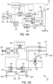
- a system for measuring an amount of liquid in a pumping chamber of a pneumatically actuated diaphragm pump.
- the sytem comprises a fluid inlet and fluid outlet valve connected to the pumping chamber; a diaphragm separating a pneumatically actuated control chamber from the pumping chamber, the control chamber fluidly connected to a reference chamber of known volume via a conduit that includes a reference chamber valve; the control chamber fluidly connected via one or more actuation valves to a source of positive or negative pneumatic pressure; and a controller configured to control the fluid inlet and outlet valves, the reference chamber valve, and the one or more actuation valves, and to receive pressure data from a first pressure sensor connected to the actuation chamber and a second pressure sensor connected to the reference chamber.
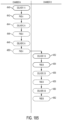
- the controller is configured to isolate the pumping chamber by closing the fluid inlet and outlet valves, charge the control chamber with a first pneumatic pressure; vent the reference chamber or fix a pneumatic pressure in the reference chamber that is different from the control chamber pneumatic pressure; measure a first control chamber pressure and a first reference chamber pressure, connect the control chamber to the reference chamber by opening the reference chamber valve, measure a third equalized pneumatic pressure in the control and reference chambers, and compute a control chamber volume based on an ideal gas model that assumes an adiabatic pressure equalization process in the reference chamber and a polytropic pressure equalization process in the control chamber.
- the model optionally can further assume an isothermal process in the conduit as a gas moves from the control chamber to the reference chamber during the equalization process.
- the model applied to the control chamber can also use a polytropic coefficient in the ideal gas model, wherein the controller is programmed to vary the polytropic coefficient as a pre-defined function of the control chamber volume.
- the controller can also be programmed to compute a polytropic coefficient based on an estimated volume of the control chamber using a model that assumes an adiabatic pressure equalization process in the control chamber.
- a system for measuring an amount of liquid in a pumping chamber of a pneumatically actuated diaphragm pump.
- the system comprises a fluid inlet and fluid outlet valve connected to the pumping chamber; a diaphragm separating a pneumatically actuated control chamber from the pumping chamber, the control chamber fluidly connected to a reference chamber of known volume via a conduit that includes a reference chamber valve; the control chamber fluidly connected via one or more actuation valves to a source of positive or negative pneumatic pressure; and a controller configured to control the fluid inlet and outlet valves, the reference chamber valve, and the one or more actuation valves, and to receive pressure data from a first pressure sensor connected to the actuation chamber and a second pressure sensor connected to the reference chamber.
- the controller is configured to isolate the pumping chamber by closing the fluid inlet and outlet valves, charge the control chamber with a first pneumatic pressure; vent the reference chamber or fix a pneumatic pressure in the reference chamber that is different from the control chamber pneumatic pressure; measure a first control chamber pressure and a first reference chamber pressure, connect the control chamber to the reference chamber by opening the reference chamber valve and equalizing pressures between the control chamber and the reference chamber, measure a third equalized pneumatic pressure in the control and reference chambers.
- the controller is configured to compute a control chamber volume based on an ideal gas model that assumes the presence of three closed mass systems of a gas comprising: a first mass system that occupies the control chamber at the end of pressure equalization; a second mass system that occupies the reference chamber before pressure equalization; and a third mass system that occupies the conduit, a part of the control chamber and a part of the reference chamber after equalization of pressure begins between the control and reference chambers.
- the model can optionally assume an expansion of the first mass system after pressure equalization begins, the expansion being modeled as a polytropic process.
- the model can also assume a compression of the second mass system after pressure equalization begins, the compression being modeled as an adiabatic process.
- the third mass system can be modeled to be subdivided into component volumes, a first component volume occupying part of the control chamber and being modeled polytropically, a second component volume occupying part of the reference chamber and being modeled adiabatically, and a third component volume occupying the conduit and being modeled isothermally.
- a system for measuring an amount of liquid in a pumping chamber of a pneumatically actuated diaphragm pump.
- the system comprises a fluid inlet and fluid outlet valve connected to the pumping chamber; a diaphragm separating a pneumatically actuated control chamber from the pumping chamber, the control chamber fluidly connected to a reference chamber of known volume via a conduit that includes a reference chamber valve; the control chamber fluidly connected via one or more actuation valves to a source of positive or negative pneumatic pressure; and a controller configured to control the fluid inlet and outlet valves, the reference chamber valve, and the one or more actuation valves, and to receive pressure data from a first pressure sensor connected to the actuation chamber and a second pressure sensor connected to the reference chamber.
- the controller is configured to isolate the pumping chamber by closing the fluid inlet and outlet valves, charge the control chamber with a first pneumatic pressure; vent the reference chamber or fix a pneumatic pressure in the reference chamber that is different from the control chamber pneumatic pressure; measure a first control chamber pressure and a first reference chamber pressure, connect the control chamber to the reference chamber by opening the reference chamber valve and equalizing pressures between the control chamber and the reference chamber, measure a third equalized pneumatic pressure in the control and reference chambers.
- the controller is configured to compute the control chamber volume based on an ideal gas model that assumes the presence of three closed mass systems of a gas comprising: a first mass system that occupies the control chamber before pressure equalization; a second mass system that occupies the reference chamber at the end of pressure equalization; and a third mass system that occupies the conduit, a part of the control chamber and a part of the reference chamber after equalization of pressure begins between the control and reference chambers.
- the model can optionally assume a compression of the first mass system after pressure equalization begins, the compression being modeled as a polytropic process.
- the model can also assume an expansion of the second mass system after pressure equalization begins, the expansion being modeled as an adiabatic process.
- the third mass system can be modeled to be subdivided into component volumes, a first component volume occupying part of the control chamber being modeled polytropically, a second component volume occupying part of the reference chamber being modeled adiabatically, and a third component volume occupying the conduit being modeled isothermally.
- a system for measuring an amount of liquid in a pumping chamber of a pneumatically actuated diaphragm pump.
- the system comprises a fluid inlet and fluid outlet valve connected to the pumping chamber; a diaphragm separating a pneumatically actuated control chamber from the pumping chamber, the control chamber fluidly connected to a reference chamber of known volume via a conduit that includes a reference chamber valve; the control chamber fluidly connected via one or more actuation valves to a source of positive or negative pneumatic pressure; and a controller configured to control the fluid inlet and outlet valves, the reference chamber valve, and the one or more actuation valves, and to receive pressure data from a first pressure sensor connected to the actuation chamber and a second pressure sensor connected to the reference chamber.
- the controller is configured to isolate the pumping chamber by closing the fluid inlet and outlet valves, charge the control chamber with a first pneumatic pressure; vent the reference chamber or fix a pneumatic pressure in the reference chamber that is different from the control chamber pneumatic pressure; measure a first control chamber pressure and a first reference chamber pressure, connect the control chamber to the reference chamber by opening the reference chamber valve and equalizing pressures between the control chamber and the reference chamber, measure a third equalized pneumatic pressure in the control and reference chambers.
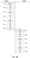
- the controller is configured to compute a control chamber volume based on an ideal gas model under a polytropic process, and is configured to select a polytropic coefficient for the model using a pre-determined function in which the value of the polytropic coefficient depends on and varies with the control chamber volume.
- the pre-determined function can be determined by fixing the control chamber volume at a known volume, and calculating a polytropic coefficient corresponding to the known volumes of the control and reference chambers, and the measured first, second and third pressures before and after equalization of pressures. The calculation is repeated a plurality of times, each time corresponding to fixing the control chamber volume at a different known volume.
- the function can correspond to a stored look-up table from which the controller selects a polytropic coefficient corresponding to the volume of the control chamber being computed.
- the function can correspond to an equation that has been fitted to a plurality of calculated polytropic coefficients corresponding to a series of known control chamber volumes.
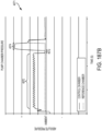
- a method for the measuring a volume comprises: providing a chamber defined by one or more rigid impermeable boundaries and one movable impermeable boundary, wherein the volume of the chamber varies; fixing the movable boundary; charging the chamber with a gas to a pre-charge pressure value above ambient pressure and allowing the gas to come to thermal equilibrium with the boundaries of the chamber; recording the pressure in the chamber as the first pressure; releasing the movable boundary and allowing the gas in the chamber to displace the movable boundary, which displaces a volume of fluid equivalent to the volume swept by the movable boundary; allowing the gas in the chamber to again come to thermal equilibrium with the boundaries of the chamber; recording the volume of displaced fluid; recording the pressure in the chamber as the second pressure; and determining the volume of the chamber before displacement based on the first pressure, the second pressure, the volume of displaced fluid, and an ideal gas model of the chamber gas between the recording of the first pressure and the recording of the second pressure.
- the ideal gas model can assume an isothermal process between the recording of the first pressure and the recording of the second pressure.
- the method can further comprise determining the volume of the chamber after displacement based on the first pressure, the second pressure, the volume of displaced fluid and an ideal gas model of the chamber gas between the recording of the first pressure and the recording of the second pressure.
- a method for calibrating a known volume-measurement-procedure comprising: providing a liquid pump apparatus having a pump chamber separated from a pump control chamber by a movable membrane, and a reference chamber that is fluidly connectable to the pump control chamber, wherein the pump chamber is selectively connected to a liquid volume measurement device; filling the liquid side of the pump chamber so it occupies most of the pump control chamber; making a first provisional measurement of the pump control chamber volume using a known volume measurement procedure; charging the pump control chamber with a gas to a pre-charge pressure value and allowing the gas to come to thermal equilibrium with the boundaries of the pump control chamber; firstly recording the pressure in the pump control chamber as the first pressure; connecting the pump to the volume measurement device, so that the charge pressure displaces the membrane, which displaces liquid; allowing the gas in the pump control chamber to come to thermal equilibrium with boundaries of the pump control chamber; recording the volume of displaced fluid measured by the volume measurement device; secondly recording the pressure in the pump control chamber as the second pressure
- the method can further comprise: repeating the steps of making, charging, firstly recording the pressure, connecting, allowing, recording the volume, secondly recording the pressure, and determining until substantially all the liquid in pump chamber has been expelled; storing the calibration coefficient and the provisional volume measurements as a related pairs; and fitting a calibration equation to the stored values of calibration coefficient as a function of the related provisional volume measurements.
- the accuracy of the determined volumes of the pump control chamber can be improved by averaging 1) a given determined volume, 2) the preceding determined volume plus the preceding displaced water volume, and 3) the following determined volume minus the following displaced water volume.
- the accuracy of the first determined volume of the pump control chamber can also be improved by averaging 1) the first determined volume, and 2) the following determined volume minus the following displaced water volume.
- the accuracy of the last determined volume of the pump control chamber can also be improved by averaging 1) the last determined volume, and 2) the preceding determined volume plus the preceding displaced water volume.
- Determining the volume of the pump control chamber can be based on the ideal gas model assumes a polytropic process with an expansion coefficient near 1.
- the method can further: executing a plurality of pumping strokes with the liquid pump apparatus, wherein the known volume-measurement-procedure occurs after each fill and deliver stork and the volume of liquid displaced by the liquid pump apparatus is recorded for each stroke; correcting the volumetric results of the known volume-measurement-procedure with the calibration equation; calculating a volume measurement error based on the corrected volumetric results and the recorded volume of displaced liquid; re-determining the volumes of the pump control chamber before displacement based an ideal gas model, where the polytropic coefficient is adjusted based on the volume measurement error; re-calculating the calibration coefficients; re-correcting the volumetric results of the known volume-measurement-procedure with the re-calculated calibration equation; and re-calculating the volume measurement error based on the re-corrected volumetric results and the recorded volume of displaced liquid.
- a system for measuring an amount of liquid in a pumping chamber of a pneumatically actuated diaphragm pump comprising: a fluid inlet and fluid outlet valve connected to the pumping chamber; a diaphragm separating a pneumatically actuated control chamber from the pumping chamber, the control chamber fluidly connected to a reference chamber of known volume via a conduit that includes a reference chamber valve; the control chamber fluidly connected via one or more actuation valves to a source of positive or negative pneumatic pressure; a controller configured to control the fluid inlet and outlet valves, the reference chamber valve, and the one or more actuation valves, and to receive pressure data from a first pressure sensor connected to the actuation chamber and a second pressure sensor connected to the reference chamber; wherein the controller is configured to isolate the pumping chamber by closing the fluid inlet and outlet valves, charge the control chamber with a first pneumatic pressure; vent the reference chamber or fix a pneumatic pressure in the reference chamber that is different from the control chamber pneumatic pressure;
- the pre-determined function optionally can be determined by fixing the control chamber volume at a known volume, and calculating the estimate of the control chamber volume and a polytropic coefficient corresponding to the known volumes of the control and reference chambers, and the measured first, second and third pressures before and after equalization of pressures; wherein said calculation is repeated a plurality of times, each said time corresponding to fixing the control chamber volume at a different known volume.
- the function can correspond to a stored look-up table from which the controller selects a polytropic coefficient corresponding to the estimate of control chamber volume being computed.
- the function can also correspond to an equation that has been fitted to a plurality of calculated polytropic coefficients corresponding to a series of estimated control chamber volumes.
- a system for measuring an amount of liquid in a pumping chamber of a pneumatically actuated diaphragm pump comprising: a fluid inlet and fluid outlet valve connected to the pumping chamber; a diaphragm separating a pneumatically actuated control chamber from the pumping chamber, the control chamber fluidly connected to a reference chamber of known volume via a conduit that includes a reference chamber valve; the control chamber fluidly connected via one or more actuation valves to a source of positive or negative pneumatic pressure; a controller configured to control the fluid inlet and outlet valves, the reference chamber valve, and the one or more actuation valves, and to receive pressure data from a first pressure sensor connected to the actuation chamber and a second pressure sensor connected to the reference chamber; wherein the controller is configured to isolate the pumping chamber by closing the fluid inlet and outlet valves, charge the control chamber with a first pneumatic pressure; vent the reference chamber or fix a pneumatic pressure in the reference chamber that is different from the control chamber pneumatic pressure;
- the pre-determined function optionally can be determined by fixing the control chamber volume at a known volume, and calculating a polytropic coefficient corresponding to the known volumes of the control and reference chambers, and the measured first, second and third pressures before and after equalization of pressures; wherein said calculation is repeated a plurality of times, each said time corresponding to fixing the control chamber volume at a different known volume.
- the function can correspond to a stored look-up table from which the controller selects a polytropic coefficient corresponding to the volume of the control chamber being computed.
- the function can also correspond to an equation that has been fitted to a plurality of calculated polytropic coefficients corresponding to a series of known control chamber volumes.
- a method for calibrating a known volume measurement procedure of claim 2a, wherein the accuracy of the determined volumes of the pump control chamber are improved by averaging1) a given determined volume, 2) the preceding determined volume plus the preceding displaced water volume, and 3) the following determined volume minus the following displaced water volume.
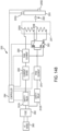
- a system for calculating a change in fluid volume in a pumping chamber of a pneumatically actuated diaphragm pump using a gas having a heat capacity ratio of n.
- the system comprises a control chamber separated from the pumping chamber by a flexible diaphragm; a fluid inlet or outlet of the pumping chamber; a valve connecting the control chamber to a pressurized source of the gas; a pressure sensor fluidly connected to the control chamber; and a controller that receives pressure data from the pressure sensor, that controls the valve, and that is configured to regulate pressure in the control chamber by opening or closing the valve.
- the controller is configured to compute a change in volume of the control chamber as fluid enters or leaves the pumping chamber by monitoring a pressure change in the control chamber when the valve is closed. This computation assigns a first chamber volume to a first measured pressure, and calculates a second chamber volume based on a second later measured pressure using an equation in which a ratio of the second measured pressure to the first measured pressure is assumed to be equal to a ratio of the first chamber volume to the second chamber volume, raised to a power between 1 and n.
- the assigned first chamber volume can be derived from an initial condition in which the control chamber is pressurized with air, the pumping chamber and control chamber are isolated, a measurement of control chamber pressure is taken, the control chamber is connected to a reference chamber having a known volume and measured pressure, and the controller derives an initial volume of the control chamber using a model based on an ideal gas equation.
- the controller can calculate a third chamber volume as fluid continues to enter or leave the pumping chamber by assigning the second chamber volume to the second measured pressure and calculating a third chamber volume based on a third measured pressure using an equation in which a ratio of the third measured pressure to the second measured pressure is assumed to be equal to a ratio of the second chamber volume to the third chamber volume, raised to a power between 1 and n.
- the controller can calculate a fluid flow into or out of the pumping chamber based on a difference between the first, second and third chamber volumes.
- the controller can repeat the calculations periodically during a time period in which fluid continues to enter or leave the pumping chamber, and can suspend the calculations during a time period in which the valve is opened to connect the control chamber with the pressurized source of the gas.
- the pressurized source of the gas can be a positively pressurized source or a negatively pressurized source.
- the gas can be air.
- the value of n can be approximately 1.4.
- n can be adjusted by the controller by comparing a cumulative calculated volume of fluid moved into or out of the pumping chamber during a pump stroke to a volume change in the pumping chamber calculated from an initial volume determination at a beginning of the pump stroke and a final volume determination at an end of the pump stroke.
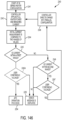
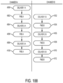
- a method for determining an amount of fluid delivered by a diaphragm pump having a pumping chamber separated from a pneumatically actuated control chamber by a diaphragm, and having pneumatically actuated inlet and outlet valves.
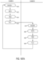
- the method is implemented by a controller that closes the outlet valve, opens the inlet valve, and connects the control chamber to a negative pressure source to apply negative pneumatic pressure to the diaphragm pump to draw fluid into the pumping chamber.
- the controller closes the inlet valve, connects the control chamber to the positive pressure source, isolates the control chamber, measures a first control chamber pressure, measures a first reference chamber pressure in a reference chamber having a known volume, connects the control chamber to the reference chamber, and calculates a first volume of the control chamber. It then opens the outlet valve, and connects the control chamber to a positive pressure source to apply a positive pneumatic pressure to the diaphragm pump to expel fluid from the pumping chamber.
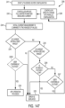
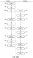
- a method for determining an amount of fluid delivered by a pumping cassette comprising a first and a second diaphragm pump each said diaphragm pump having a pumping chamber separated from a pneumatically actuated control chamber by a diaphragm, and each having pneumatically actuated inlet and outlet valves, the method comprising having a controller perform for each of diaphragm pumps the steps of: closing the outlet valve, opening the inlet valve, and connecting the control chamber to a negative pressure source to apply negative pneumatic pressure to the diaphragm pump to draw fluid into the pumping chamber; closing the inlet valve, connecting the control chamber to the positive pressure source, isolating the control chamber, measuring a first control chamber pressure, measuring a first reference chamber pressure in a reference chamber having a known volume, connecting the control chamber to the reference chamber, and calculating a first volume of the control chamber; opening the outlet valve, and connecting the control chamber to a positive pressure source to apply a positive pneumatic pressure to the dia
- Expelling fluid from the pumping chamber of the second diaphragm pump is performed after the control chamber of the first diaphragm pump is vented, and expelling fluid from the pumping chamber of the first diaphragm pump is performed after the control chamber of the second diaphragm pump is vented.
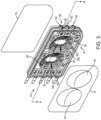
- a system for measuring a volume of liquid in a pumping chamber of a peritoneal dialysis pump cassette comprising: a base unit in which the pump cassette can be installed, the base unit including a control block having a control chamber depression configured to mate with the pumping chamber of the pumping cassette, and to move a flexible diaphragm between the pumping chamber and the control chamber under positive or negative pneumatic pressure.
- the control chamber depression is in communication via one or more pump actuation valves in the base unit with a source of positive or negative pressure, and in communication via a vent valve in the base unit with a vent connected to atmospheric pressure.
- a controller is configured to control the one or more pump actuation valves to operate the pumping cassette to fill the pumping chamber with liquid and to deliver liquid from the pumping chamber.
- the controller is configured to control one or more pneumatically actuated membrane inlet and outlet valves in the pump cassette via one or more inlet and outlet actuation valves in the base unit connected to the source of positive or negative pneumatic pressure.
- the controller is also configured to measure pneumatic pressure in the control chamber via a pressure sensor, and to calculate a volume of liquid in the pumping chamber, the calculation involving pneumatically pressurizing the control chamber before taking a pressure measurement.
- the controller is also configured to connect the control chamber with the vent after commanding a liquid delivery stroke of the pump cassette and before pneumatically pressurizing the control chamber to perform a pumping chamber liquid volume calculation.
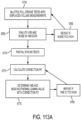
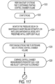
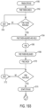
- a system for adjusting negative pressure used to withdraw fluid from a cavity of a patient, the system comprising: a pump configured to provide negative pressure to a fluid line connected to the cavity; a controller configured to measure and control the negative pressure provided by the pump. The controller is also configured to measure a rate of flow of fluid from the fluid line to the pump. The controller is arranged to control the pump by providing a first negative pressure to the fluid line, measuring the rate of fluid flow, and control the pump by providing a second negative pressure to the fluid line that is greater in magnitude than the first negative pressure if the measured rate of fluid flow exceeds a pre-determined value.
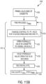
- a system for adjusting negative pressure used to withdraw fluid from a cavity of a patient.
- the system comprises: a pump configured to provide negative or positive pressure to a fluid line connected to the cavity; a controller configured to measure and control the pressure provided by the pump.
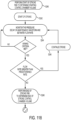
- Tthe controller is also configured to measure a rate of flow of fluid from the fluid line to the pump, so that the controller is arranged to control the pump by providing negative pressure to the fluid line, measuring the rate of fluid flow, and control the pump by providing a positive pressure to the fluid line if the measured rate of fluid flow is less than a pre-determined value, and wherein the controller is arranged to re-apply negative pressure to the fluid line if a measured fluid flow upon application of the positive pressure is greater than a pre-determined amount.
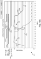
- a system for adjusting negative pressure used to withdraw fluid from a cavity of a patient, the system comprising: a pump configured to provide negative pressure to a fluid line connected to the cavity; a controller configured to measure and control the pressure provided by the pump. The controller is also configured to measure a flow rate of fluid from the fluid line to the pump. The controller is then arranged to control the pump by providing negative pressure in an amount that varies continuously as a function of the measured flow rate of the fluid, such that the variation in negative pressure applied by the pump is limited to within a pre-determined range of negative pressures.
- a system for adjusting negative pressure used to withdraw fluid from a cavity of a patient, the system comprising: a pump configured to provide negative pressure to a fluid line connected to the cavity; a controller configured to measure and control the pressure provided by the pump; the controller also being configured to measure a flow rate of fluid from the fluid line to the pump.
- a user interface is configured to provide a user a measure of the negative pressure applied by the pump, and configured to receive input from the user to adjust the amount of negative pressure applied by the pump, such that the controller is arranged to receive via the user interface a command from the user to adjust the negative pressure applied by the pump, and to effectuate the adjustment.
- a system for adjusting negative pressure used to withdraw fluid from a cavity of a patient, the system comprising: a pump configured to provide negative pressure to a fluid line connected to the cavity; a controller configured to measure and control the pressure provided by the pump; the controller also configured to measure a flow rate of fluid from the fluid line to the pump, and to compute a pumping duration based on the measured flow rate.
- a user interface is configured to provide a user a measure of the negative pressure applied by the pump, and configured to receive input from the user to adjust the amount of negative pressure applied by the pump, such that the controller is arranged to receive via the user interface a command from the user to adjust the negative pressure applied by the pump, to compute a change in the pumping duration resulting from the adjustment, to display information about the change in pumping duration on the user interface, and to receive from the user a command to proceed or not proceed with the adjustment.
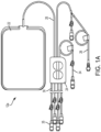
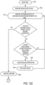
- a system for performing automated peritoneal dialysis comprising; a cycler comprising a fluid pump and controller, the controller configured to measure and control an amount of fluid pumped to a peritoneal cavity and to track a remaining volume of the fluid in a solution bag.
- the controller is configured to: control a dialysis therapy by administering a pre-determined number of therapy cycles, each therapy cycle comprising a fill phase, dwell phase and drain phase; and maintain a pre-determined minimum volume of intra-peritioneal fluid during the dwell phase.
- the controller is also configured to further adjust the fill volumes of the remaining number of therapy cycles, or the duration of the dwell phases of the remaining number of therapy cycles to prevent an accumulation of intra-peritoneal fluid during the remaining therapy cycles from exceeding a pre-determined maximum intra-peritoneal volume of fluid.
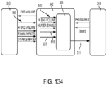
- a system in an automated peritoneal dialysis apparatus for replenishing a heater bag with fluid during a dialysis therapy comprising a fluid fill phase, a fluid dwell phase, and a fluid drain phase.
- the system comprises a controller configured to: track a remaining volume of fluid remaining in the heater bag; compute a replenish volume of fluid to be infused into the heater bag comprising subtracting the remaining volume from a fill volume of fluid to be infused into a patient in a subsequent fill phase of the dialysis therapy; compute a replenish volume transfer time required to transfer the replenish volume from a fluid source to the heater bag; compute a replenish volume heating time required to heat the replenish volume to within a pre-determined range of a pre-determined temperature set point; and compute a remaining dwell time required to complete the fluid dwell phase.
- the controller is also configured to control a fluid heater of the peritoneal dialysis apparatus to heat the replenish fluid as it enters the heater bag, and to control a fluid pump of the peritoneal dialysis apparatus to initiate pumping of the replenish volume to the heater bag when the remaining dwell time is equal to or greater than the greater of the replenish volume transfer time or the replenish volume heating time.
- a system for replenishing a fluid heater bag of a medical fluid delivery apparatus comprising: a processor configured to receive temperature data associated with a fluid in the heater bag, to control a heater to heat the fluid in the heater bag, to control a fluid pump to pump the fluid in a replenish operation into the heater bag from a fluid source, to pump the fluid in a fill phase out of the heater bag to a patient, to control a dwell phase during which the fluid remains in the patient, and to pump the fluid in a drain phase out of the patient to a destination.
- the controller is further configured to determine a replenish volume to be transferred to the heater bag during the replenish operation, the replenish volume determination made by subtracting the volume of fluid in the bag at the beginning of the replenish operation from a volume of fluid to be pumped to the patient in the next fill phase; compute a replenish volume transfer time required to transfer the replenish volume from the fluid source to the heater bag; compute a replenish volume heating time required to heat the fluid to within a pre-determined range of a pre-determined temperature set point; compute a drain time required to complete the drain phase; and control the fluid pump to initiate pumping of the fluid in the replenish operation at a remaining dwell time during the dwell phase that is approximately equal to the greater of (1) the drain time plus the replenish volume heating time or (2) the drain time plus the replenish volume transfer time.
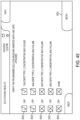
- a solution expiration timing system for an automated dialysis apparatus connected to a first fluid reservoir and a fluid heating reservoir.
- the system comprises a controller configured to begin a first solution expiration timer when a fluid is pumped from the first fluid reservoir to the fluid heating reservoir; begin a second solution expiration timer when the fluid in the fluid heating reservoir achieves a pre-determined temperature; wherein the controller is configured to declare a first expiration time when a first pre-determined time interval has elapsed, and to declare a second expiration time when a second pre-determined time interval has elapsed; and wherein the controller stops fluid transfer from the first fluid reservoir to the fluid heating reservoir at the first expiration time, and stops fluid transfer from the fluid heating reservoir to a user at the second expiration time.
- a solution expiration timing system for an automated dialysis apparatus connected to a first fluid reservoir containing a first fluid and a second fluid reservoir containing a second fluid.
- the system comprises a controller configured to: begin a first solution expiration timer when the first fluid is pumped from the first fluid reservoir to a fluid heating reservoir; begin a second solution expiration timer when the second fluid is pumped from the second fluid reservoir to the fluid heating reservoir; wherein the controller is configured to declare a first expiration time when a first pre-determined time interval has elapsed, and to declare a second expiration time when a second pre-determined time interval has elapsed; and wherein the controller stops fluid transfer from the first fluid reservoir to the fluid heating reservoir at the first expiration time, and stops fluid transfer from the second fluid reservoir to the fluid heating reservoir at the second expiration time.
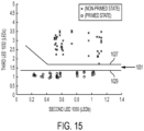
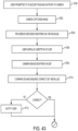
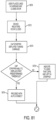
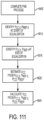
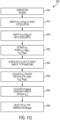
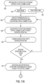
- a system for detecting that a fluid line is primed with liquid.
- the sytem comprises a fluid pump having a pumping chamber configured to pump a liquid from a proximal portion to a distal portion of the fluid line at a pre-determined pressure; a sensor configured to measure the flow of liquid in the fluid line or to measure pressure in the pumping chamber to determine the flow of liquid in the fluid line; and a controller configured to receive data from the sensor and to compare the flow of liquid or a change in the flow of liquid in the fluid line with a pre-determined value.
- the distal portion of the fluid line comprises a flow restrictor that measurably reduces the flow of liquid in the fluid line when air in the distal portion of the fluid line is replaced by the liquid being pumped by the pump; and the controller declares the fluid line to be primed when the reduction in measured liquid flow reaches the predetermined value.
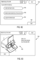
- an automated peritoneal dialysis cycler is equipped with an autoconnect apparatus for spiking solution lines for dialysis therapy.
- a cap detection system is disclosed for detecting the presence of a solution line or spike cap on a cap stripper, the cap detection system comprising: a position sensor for the cap stripper configured to detect a position of the cap stripper relative to a plane in which a plurality of cassette spikes or a plurality of solution lines reside when placed in the cycler; a controller configured to command movement of the cap stripper toward or away from the plane, or laterally in a direction parallel with the plane, and to receive information from the position sensor to compare the position of the cap stripper relative to a first or second pre-determined fully deployed position of the cap stripper toward the plane.
- the controller is configured to: command the cap stripper to move toward the plane when one or more solution lines are installed in the cycler, and to issue an alert if a cap on the cap stripper prevents a final position of the cap stripper from reaching the first pre-determined fully deployed position; or command the cap stripper to move laterally a pre-determined distance and then toward the plane when no solution lines are installed in the cycler, and to issue an alert if a cap on the cap stripper prevents a final position of the cap stripper from reaching the second pre-determined fully deployed position.
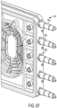
- an identification system for a fluid line connected to a fluid container for medical use.
- the system comprises an image sensor configured to read an image generated by fluorescent light, the image comprising a pattern of coded information characterizing the fluid in the container; a fluid line mount configured to hold the fluid line in a fixed position within a field of view of the image sensor; an identification tag attached to a portion of the fluid line on or near the mount; the identification tag having an identifying marking arranged to emit fluorescent light in the pattern of the image in response to absorption of light having a non-visible wavelength; an emitter configured to emit light in the non-visible wavelength onto the identification tag; and a controller configured to receive an electronic signal from the image sensor and to decode the information in the image pattern emitted by the identifying marking of the identification tag.
- a brace for a distal portion of a fluid line, the fluid line configured to receive a hollow spike in a fluid handling apparatus, the brace comprising: a rigid clamping member configured to encircle the distal portion of the fluid line after being mounted on the distal portion of the fluid line, having one or more features on an inside surface of the clamping member configured to cooperate with one or more complementary features on an outside surface of the distal portion of the fluid line.
- the brace is arranged to be mountable on the distal portion of the fluid line to constrain it from bending out of alignment with a longitudinal axis of the hollow spike before or after an initiation of a spiking of the distal portion of the fluid line.
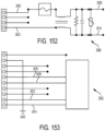
- an electronic circuit for reducing touch or leakage current from a heating element of an automated peritoneal dialysis apparatus.
- the circuit comprises: a first relay connecting a first pole of an AC mains source to a first end of the heating element; a second relay connecting a second pole of the AC mains source to a second end of the heating element; and a controller configured to control current delivery to the heating element by transmitting an on signal to both the first and second relays or an off signal to both the first and second relays, the on signal causing AC mains current to flow through the heating element, and the off signal preventing AC mains current from flowing through the heating element.
- the heating element is isolated from AC mains voltage when the controller transmits an off signal.
- an electronic circuit for delivering electric power to an automated peritoneal dialysis apparatus from a power source having a first voltage or a higher second voltage
- the electronic circuit comprising: a heater comprising a first heater element connected to a second heater element by a heater select relay, the heater select relay configured to connect the first heater element either in series or in parallel with the second heater element; a current sense element configured to measure a current flow through the heater; a controller configured to set a default configuration of the heater select realy on powering up so that the first heater element is in series with the second heater element; wherein the controller is programmed to receive information on current flow from the current sense element, and is programmed to command the heater select relay to set the first heater element in parallel with the second heater element if a measured current is less than a pre-determined target current for the heater.
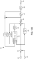
- a control system for a heater of an automated peritoneal dialysis apparatus comprising: a resistive heating element; a solid state relay connecting an electrical power source to the heating element; a first processor configured to generate and send a pulse width modulated signal to a gating circuit; a second processor configured to generate and send a safety signal to the gating circuit; wherein the gating circuit is configured to reproduce or transmit the pulse width modulated signal to operate the solid state relay if the safety signal is in a first mode, and is configured to prevent the operation of the solid state relay if the safety signal is in a second mode.
- the gating circuit optionally can operate the solid state relay through optical transmission.
- the optical transmission can be performed using a light emitting diode of an opto-isolator.
- the solid state relay can comprise a triac or a pair of silicon control rectifiers.
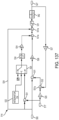
- the solid state relay can connects a first pole of an AC mains voltage source to the heating element, and a second solid state relay connects a second pole of the AC mains voltage source to the heating element, such that the pulse width modulated signal reproduced or transmitted by the gating circuit operates both the solid state relay and the second solid state relay.
- the solid state relay can also connect a first pole of an AC mains voltage source to the heating element, and a second solid state relay connects a second pole of the AC mains voltage source to the heating element, such that a second gating circuit is configured to receive the pulse width modulated signal from the first processor and the safety signal from the second processor, and such that the second gating circuit is configured to reproduce or transmit the pulse width modulated signal to operate the second solid state relay if the safety signal is in the first mode, and is configured to prevent the operation of the second solid state relay if the safety signal is in the second mode.
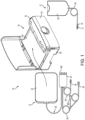
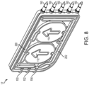
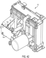
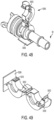
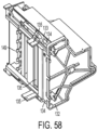
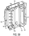
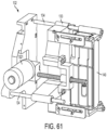
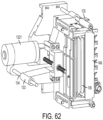
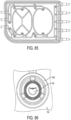
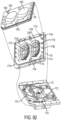
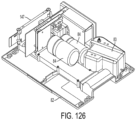
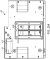
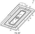
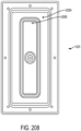
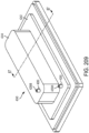
- a housing for an automated peritoneal dialysis apparatus comprising: a dual pressure reservoir integrally formed in the housing, the dual pressure reservoir having a first section separated from a second section by a dividing wall; the first section configured for positive air pressurization by a pump via a first port; the second section configured for negative air pressurization by the pump via a second port; and a cover plate for enclosing the first and second sections, said cover plate forming a seal against a perimeter wall of the first section, a perimeter wall of the second section, and the dividing wall between the first and second sections.
- a housing for an automated peritoneal dialysis apparatus that comprises: a dual pressure reservoir integrally formed in the housing, the dual pressure reservoir having a first section separated from a second section by a dividing wall; the first section configured for positive air pressurization by a pump via a first port, and comprising a first perimeter wall joining with the dividing wall and a first set of one or more stiffening members extending from a portion of the first perimeter wall to the dividing wall; the second section configured for negative air pressurization by the pump via a second port, and comprising a second perimeter wall joining with the dividing wall and a second set of one or more stiffening members extending from a portion of the second perimeter wall to the dividing wall; and a cover plate for enclosing the first and second sections, said cover plate forming a seal against the first and second perimeter walls and the dividing wall between the first and second sections.
- a housing is also for an automated peritoneal dialysis apparatus comprising: a dual pressure reservoir integrally formed in the housing, the dual pressure reservoir having a first section separated from a second section by a dividing wall; the first section configured for positive air pressurization by a pump via a first port, and comprising a first perimeter wall joining with the dividing wall; the second section configured for negative air pressurization by the pump via a second port, and comprising a second perimeter wall joining with the dividing; and a cover plate for enclosing the first and second sections, said cover plate forming a seal against the first and second perimeter walls and the dividing wall between the first and second sections; such that a plurality of stiffening members are attached to an inside surface of the cover plate, so that when the cover plate is attached to the dual pressure reservoir, a first set of said stiffening members extends in the first section from a portion of the first perimeter wall to the dividng wall, and a second set of said stiffening members extends in the second section from a portion of
- a housing for a dual pressure air reservoir comprising: a first reservoir surrounding a second reservoir, the first and second reservoirs separated by a dividing wall, and the first reservoir having an outer perimeter wall; the first reservoir configured for negative air pressurization by a pump via a first port; the second reservoir configured for positive air pressurization by the pump via a second port; a cover plate for enclosing the first and second reservoirs, said cover plate forming a seal against the outer perimeter wall of the first reservoir and the dividing wall between the first and second reservoirs; such that a surface area of the cover plate defined by outer perimeter wall and the dividing wall is greater than a surface area of the cover plate defined by an area within the dividing wall; and such that a depth of the second reservoir is greater than a depth of the first reservoir so that a volume of the first reservoir is approximately equal to a volume of the second reservoir.
- aspects of the invention are described in relation to a peritoneal dialysis system, certain aspects of the invention can be used in other medical applications, including infusion systems such as intravenous infusion systems or extracorporeal blood flow systems, and irrigation and/or fluid exchange systems for the stomach, intestinal tract, urinary bladder, pleural space or other body or organ cavity.
- infusion systems such as intravenous infusion systems or extracorporeal blood flow systems
- irrigation and/or fluid exchange systems for the stomach, intestinal tract, urinary bladder, pleural space or other body or organ cavity.
- aspects of the invention are not limited to use in peritoneal dialysis in particular, or dialysis in general.
- FIG. 1 shows an automated peritoneal dialysis (APD) system 10 that may incorporate one or more aspects of the invention.
- the system 10 in this illustrative embodiment includes a dialysate delivery set 12 (which, in certain embodiments, can be a disposable set), a cycler 14 that interacts with the delivery set 12 to pump liquid provided by a solution container 20 (e.g., a bag), and a control system 16 (e.g., including a programmed computer or other data processor, computer memory, an interface to provide information to and receive input from a user or other device, one or more sensors, actuators, relays, pneumatic pumps, tanks, a power supply, and/or other suitable components - only a few buttons for receiving user control input are shown in FIG.
- a dialysate delivery set 12 which, in certain embodiments, can be a disposable set
- a cycler 14 that interacts with the delivery set 12 to pump liquid provided by a solution container 20 (e.g., a bag)
- the cycler 14 and the control system 16 are associated with a common housing 82, but may be associated with two or more housings and/or may be separate from each other.
- the cycler 14 may have a compact footprint, suited for operation upon a table top or other relatively small surface normally found in the home.
- the cycler 14 may be lightweight and portable, e.g., carried by hand via handles at opposite sides of the housing 82.
- the set 12 in this embodiment is intended to be a single use, disposable item, but instead may have one or more reusable components, or may be reusable in its entirety.
- the user associates the set 12 with the cycler 14 before beginning each APD therapy session, e.g., by mounting a cassette 24 within a front door 141 of the cycler 14, which interacts with the cassette 24 to pump and control fluid flow in the various lines of the set 12. For example, dialysate may be pumped both to and from the patient to effect APD. Post therapy, the user may remove all or part of the components of the set 12 from the cycler 14.
- the cycler 14 may be configured to operate with one or more different types of cassettes 24, such as those having differently sized patient lines 34.
- the cycler 14 may be arranged to operate with a first type of cassette with a patient line 34 sized for use with an adult patient, and a second type of cassette with a patient line 34 sized for an infant or pediatric use.
- the pediatric patient line 34 may be shorter and have a smaller inner diameter than the adult line so as to minimize the volume of the line, allowing for more controlled delivery of dialysate and helping to avoid returning a relatively large volume of used dialysate to the pediatric patient when the set 12 is used for consecutive drain and fill cycles.
- a heater bag 22, which is connected to the cassette 24 by a line 26, may be placed on a heater container receiving portion (in this case, a tray) 142 of the cycler 14.
- the cycler 14 may pump fresh dialysate (via the cassette 24) into the heater bag 22 so that the dialysate may be heated by the heater tray 142, e.g., by electric resistance heating elements associated with the tray 142 to a temperature of about 37 degrees C.
- Heated dialysate may be provided from the heater bag 22 to the patient via the cassette 24 and the patient line 34.
- the dialysate can be heated on its way to the patient as it enters, or after it exits, the cassette 24 by passing the dialysate through tubing in contact with the heater tray 142, or through an in-line fluid heater (which may be provided in the cassette 24).
- Used dialysate may be pumped from the patient via the patient line 34 to the cassette 24 and into a drain line 28, which may include one or more clamps to control flow through one or more branches of the drain line 28.
- the drain line 28 may include a connector 39 for connecting the drain line 28 to a dedicated drain receptacle, and an effluent sample port 282 for taking a sample of used dialysate for testing or other analysis.
- the user may also mount the lines 30 of one or more containers 20 within the door 141.
- the lines 30 may also be connected to a continuous or real-time dialysate preparation system.
- the lines 26, 28, 30, 34 may include a flexible tubing and/or suitable connectors and other components (such as pinch valves, etc.) as desired.
- the containers 20 may contain sterile peritoneal dialysis solution for infusion, or other materials (e.g., materials used by the cycler 14 to formulate dialysate by mixing with water, or admixing different types of dialysate solutions).
- the lines 30 may be connected to spikes 160 of the cassette 24, which are shown in FIG. 1 covered by removable caps.
- the cycler 14 may automatically remove caps from one or more spikes 160 of the cassette 24 and connect lines 30 of solution containers 20 to respective spikes 160. This feature may help reduce the possibility of infection or contamination by reducing the chance of contact of non-sterile items with the spikes 160.
- a dialysate delivery set 12a may not have cassette spikes 160. Instead, one or more solution lines 30 may be permanently affixed to the inlet ports of cassette 24, as shown in FIG. 1A . In this case, each solution line 30 may have a (capped) spike connector 35 for manual connection to a solution container or dialysate bag 20.
- the control system 16 may pace the cycler 14 through a series of fill, dwell, and/or drain cycles typical of an APD procedure. For example, during a fill phase, the cycler 14 may pump dialysate (by way of the cassette 24) from one or more containers 20 (or other source of dialysate supply) into the heater bag 22 for heating. Thereafter, the cycler 14 may infuse heated dialysate from the heater bag 22 through the cassette 24 and into the patient's peritoneal cavity via the patient line 34.
- the cycler 14 may institute a drain phase, during which the cycler 14 pumps used dialysate from the patient via the line 34 (again by way of the cassette 24), and discharges spent dialysis solution into a nearby drain (not shown) via the drain line 28.
- the cycler 14 does not necessarily require the solution containers 20 and/or the heater bag 22 to be positioned at a prescribed head height above the cycler 14, e.g., because the cycler 14 is not necessarily a gravity flow system. Instead, the cycler 14 may emulate gravity flow, or otherwise suitably control flow of dialysate solution, even with the source solution containers 20 above, below or at a same height as the cycler 14, with the patient above or below the cycler, etc.
- the cycler 14 can emulate a fixed head height during a given procedure, or the cycler 14 can change the effective head height to either increase or decrease pressure applied to the dialysate during a procedure.
- the cycler 14 may also adjust the rate of flow of dialysate.
- the cycler 14 may adjust the pressure and/or flow rate of dialysate when provided to the patient or drawn from the patient so as to reduce the patient's sensation of the fill or drain operation. Such adjustment may occur during a single fill and/or drain cycle, or may be adjusted across different fill and/or drain cycles.
- the cycler 14 may taper the pressure used to draw used dialysate from the patient near the end of a drain operation. Because the cycler 14 may establish an artificial head height, it may have the flexibility to interact with and adapt to the particular physiology or changes in the relative elevation of the patient.
- a cassette 24 may include patient and drain lines that are separately occludable with respect to solution supply lines. That is, safety critical flow to and from patient line may be controlled, e.g., by pinching the lines to stop flow, without the need to occlude flow through one or more solution supply lines.
- This feature may allow for a simplified occluder device since occlusion may be performed with respect to only two lines as opposed to occluding other lines that have little or no effect on patient safety. For example, in a circumstance where a patient or drain connection becomes disconnected, the patient and drain lines may be occluded.
- solution supply and/or heater bag lines may remain open for flow, allowing the cycler 14 to prepare for a next dialysis cycle; e.g., separate occlusion of patient and drain lines may help ensure patient safety while permitting the cycler 14 to continue to pump dialysate from one or more containers 20 to the heater bag 22 or to other solution containers 20.
- the cassette may have patient, drain and heater bag lines at one side or portion of the cassette and one or more solution supply lines at another side or portion of the cassette, e.g., an opposite side of the cassette.
- Such an arrangement may allow for separate occlusion of patient, drain or heater bag lines with respect to solution lines as discussed above.
- Physically separating the lines attached to the cassette by type or function allows for more efficient control of interaction with lines of a certain type or function.
- such an arrangement may allow for a simplified occluder design because less force is required to occlude one, two or three of these lines than all lines leading to or away from the cassette.
- this arrangement may allow for more effective automated connection of solution supply lines to the cassette, as discussed in more detail below.
- an automated de-capping and connection device may remove caps from spikes on the cassette as well as caps on solution supply lines, and connect the lines to respective spikes without interference by the patient, drain or heater bag lines.
- FIG. 2 shows an illustrative embodiment of a cassette 24 that incorporates aspects of the invention described above.
- the cassette 24 has a generally planar body and the heater bag line 26, the drain line 28 and the patient line 34 are connected at respective ports on the left end of the cassette body, while the right end of the cassette body may include five spikes 160 to which solution supply lines 30 may be connected.
- each of the spikes 160 is covered by a spike cap 63, which may be removed, exposing the respective spike and allowing connection to a respective line 30.
- the lines 30 may be attached to one or more solution containers or other sources of material, e.g., for use in dialysis and/or the formulation of dialysate, or connected to one or more collection bags for sampling purposes or for peritoneal equilibration testing (PET test).
- solution containers or other sources of material e.g., for use in dialysis and/or the formulation of dialysate
- PET test peritoneal equilibration testing
- FIGS. 3 and 4 show exploded views (perspective and top views, respectively) of the cassette 24 in this illustrative embodiment.
- the cassette 24 is formed as a relatively thin and flat member having a generally planar shape, e.g., may include components that are molded, extruded or otherwise formed from a suitable plastic.
- the cassette 24 includes a base member 18 that functions as a frame or structural member for the cassette 24 as well as forming, at least in part, various flow channels, ports, valve portions, etc.
- the base member 18 may be molded or otherwise formed from a suitable plastic or other material, such as a polymethyl methacrylate (PMMA) acrylic, or a cyclic olefin copolymer/ultra low density polyethylene (COC/ULDPE), and may be relatively rigid. In an embodiment, the ratio of COC to ULDPE can be approximately 85%/15%.
- FIG. 3 also shows the ports for the heater bag (port 150), drain (port 152) and the patient (port 154) that are formed in the base member 18. Each of these ports may be arranged in any suitable way, such as, for example, a central tube 156 extending from an outer ring or skirt 158, or a central tube alone. Flexible tubing for each of the heater bag, drain and patient lines 26, 28, 34 may be connected to the central tube 156 and engaged by the outer ring 158, if present.
- PMMA polymethyl methacrylate
- COC/ULDPE cyclic olefin copolymer/ultra low density polyethylene
- Both sides of the base member 18 may be covered, at least in part, by a membrane 15 and 16, e.g., a flexible polymer film made from, for example, polyvinyl chloride (PVC), that is cast, extruded or otherwise formed.
- the sheet may be formed as a laminate of two or more layers of poly-cyclohexylene dimethylene cyclohexanedicarboxylate (PCCE) and/or ULDPE, held together, for example, by a coextrudable adhesive (CXA).
- the membrane thickness may be in the range of approximately 0.002 to 0.020 inches thick.
- the thickness of a PVC-based membrane may be in the range of approximately 0.012 to 0.016 inches thick, and more preferably approximately 0.014 inches thick. In another preferred embodiment, such as, for example, for laminate sheets, the thickness of the laminate may be in the range of approximately 0.006 to 0.010 inches thick, and more preferably approximately 0.008 inches thick.
- Both membranes 15 and 16 may function not only to close or otherwise form a part of flowpaths of the cassette 24, but also may be moved or otherwise manipulated to open/close valve ports and/or to function as part of a pump diaphragm, septum or wall that moves fluid in the cassette 24.
- the membranes 15 and 16 may be positioned on the base member 18 and sealed (e.g., by heat, adhesive, ultrasonic welding or other means) to a rim around the periphery of the base member 18 to prevent fluid from leaking from the cassette 24.
- the membrane 15 may also be bonded to other, inner walls of the base member 18, e.g., those that form various channels, or may be pressed into sealing contact with the walls and other features of the base member 18 when the cassette 24 suitably mounted in the cycler 14.
- both of the membranes 15 and 16 may be sealed to a peripheral rim of the base member 18, e.g., to help prevent leaking of fluid from the cassette 24 upon its removal from the cycler 14 after use, yet be arranged to lie, unattached, over other portions of the base member 18.
- the cassette 24 may be squeezed between opposed gaskets or other members so that the membranes 15 and 16 are pressed into sealing contact with the base member 18 at regions inside of the periphery, thereby suitably sealing channels, valve ports, etc., from each other.
- the membrane 16 may be formed by a rigid sheet of material that is bonded or otherwise made integral with the body 18.
- the membrane 16 need not necessarily be, or include, a flexible member.
- the membrane 15 need not be flexible over its entire surface, but instead may include one or more flexible portions to permit pump and/or valve operation, and one or more rigid portions, e.g., to close flowpaths of the cassette 24.
- the cassette 24 may not include the membrane 16 or the membrane 15, e.g., where the cycler 14 includes a suitable member to seal pathways of the cassette, control valve and pump function, etc.
- the membrane 15 may include a pump chamber portion 151 ("pump membrane”) that is formed to have a shape that closely conforms to the shape of a corresponding pump chamber 181 depression in the base 18.
- the membrane 15 may be generally formed as a flat member with thermoformed (or otherwise formed) dome-like shapes 151 that conform to the pump chamber depressions of the base member 18.
- the dome-like shape of the pre-formed pump chamber portions 151 may be constructed, for example, by heating and forming the membrane over a vacuum form mold of the type shown in FIG. 5 . As shown in FIG. 5 , the vacuum may be applied through a collection of holes along the wall of the mold.
- the wall of the mold can be constructed of a porous gas-permeable material, which may result in a more uniformly smooth surface of the molded membrane.
- the molded membrane sheet 15 is trimmed while attached to the vacuum form mold. The vacuum form mold then presses the trimmed membrane sheet 15 against the cassette body 18 and bonds them together.
- the membrane sheets 15,16 are heat-welded to the cassette body 18. In this way, the membrane 15 may move relative to the pump chambers 181 to effect pumping action without requiring stretching of the membrane 15 (or at least minimal stretching of the membrane 15), both when the membrane 15 is moved maximally into the pump chambers 181 and (potentially) into contact with spacer elements 50 (e.g., as shown in solid line in FIG.
- the pump chamber portions 151 may be formed to have a size (e.g., a define a volume) that is about 85-110% of the pump chamber 181, e.g., if the pump chamber portions 151 define a volume that is about 100% of the pump chamber volume, the pump chamber portion 151 may lie in the pump chamber 181 and in contact with the spacers 50 while at rest and without being stressed.
- a size e.g., a define a volume
- the pump chamber portion 151 may lie in the pump chamber 181 and in contact with the spacers 50 while at rest and without being stressed.
- Providing greater control of the pressure used to generate a fill and delivery stroke of liquid into and out of a pump chamber may have several advantages. For example, it may be desirable to apply the minimum negative pressure possible when the pump chamber draws fluid from the patient's peritoneal cavity during a drain cycle. A patient may experience discomfort during the drain cycle of a treatment in part because of the negative pressure being applied by the pumps during a fill stroke. The added control that a pre-formed membrane can provide to the negative pressure being applied during a fill stroke may help to reduce the patient's discomfort.
- a number of other benefits may be realized by using pump membranes pre-formed to the contour of the cassette pump chamber.
- the flow rate of liquid through the pump chamber can be made more uniform, because a constant pressure or vacuum can be applied throughout the pump stroke, which in turn may simplify the process of regulating the heating of the liquid.
- temperature changes in the cassette pump may have a smaller effect on the dynamics of displacing the membrane, as well as the accuracy of measuring pressures within the pump chambers.
- pressure spikes within the fluid lines can be minimized.
- correlating the pressures measured by pressure transducers on the control (e.g. pneumatic) side of the membrane with the actual pressure of the liquid on the pump chamber side of the membrane may be simpler.
- This in turn may permit more accurate head height measurements of the patient and fluid source bags prior to therapy, improve the sensitivity of detecting air in the pump chamber, and improve the accuracy of volumetric measurements. Furthermore, eliminating the need to stretch the membrane may allow for the construction and use of pump chambers having greater volumes.
- the cassette 24 includes a pair of pump chambers 181 that are formed in the base member 18, although one pump chamber or more than two pump chambers are possible.
- the inner wall of pump chambers 181 includes spacer elements 50 that are spaced from each other and extend from the inner wall of pump chamber 18 to help prevent portions of the membrane 15 from contacting the inner wall of pump chamber 181. (As shown on the right-side pump chamber 181 in FIG. 4 , the inner wall is defined by side portions 181a and a bottom portion 181b.
- the spacers 50 extend upwardly from the bottom portion 181b in this embodiment, but could extend from the side portions 181a or be formed in other ways.) By preventing contact of the membrane 15 with the pump chamber inner wall, the spacer elements 50 may provide a dead space (or trap volume) which may help trap air or other gas in the pump chamber 181 and inhibit the gas from being pumped out of the pump chamber 181 in some circumstances. In other cases, the spacers 50 may help the gas move to an outlet of the pump chamber 181 so that the gas may be removed from the pump chamber 181, e.g., during priming.
- the spacers 50 may help prevent the membrane 15 from sticking to the pump chamber inner wall and/or allow flow to continue through the pump chamber 181, even if the membrane 15 is pressed into contact with the spacer elements 50.
- the spacers 50 help to prevent premature closure of the outlet port of the pump chamber (openings 187 and/or 191) if the sheet happens to contact the pump chamber inner wall in a non-uniform manner. Further details regarding the arrangement and/or function of spacers 50 are provided in U.S. Patent 6,302,653 and 6,382,923 , both of which are incorporated herein by reference.
- the spacer elements 50 are arranged in a kind of "stadium seating" arrangement such that the spacer elements 50 are arranged in a concentric elliptical pattern with ends of the spacer elements 50 increasing in height from the bottom portion 181b of the inner wall with distance away from the center of the pump chamber 181 to form a semi-elliptical domed shaped region (shown by dotted line in FIG. 4 ).
- Positioning spacer elements 50 such that the ends of the spacer elements 50 form a semi-elliptical region that defines the domed region intended to be swept by the pump chamber portion 151 of the membrane 15 may allow for a desired volume of dead space that minimizes any reduction to the intended stroke capacity of pump chambers 181. As can be seen in FIG. 3 (and FIG.
- the "stadium seating" arrangement in which spacer elements 50 are arranged may include “aisles” or breaks 50a in the elliptical pattern. Breaks (or aisles) 50a help to maintain an equal gas level throughout the rows (voids or dead space) 50b between spacer elements 50 as fluid is delivered from the pump chamber 181.
- the membrane 15 might bottom out on the spacer element 50 located at the outermost periphery of the pump chamber 181, trapping whatever gas or liquid is present in the void between this outermost spacer element 50 and the side portions 181a of the pump chamber wall.
- any gas and liquid in the void between the elements 50 may become trapped.
- air or other gas at the center of pump chamber 181 could be delivered while liquid remains in the outer rows.
- Supplying breaks (or aisles) 50a or other means of fluidic communication between the voids between spacer elements 50 helps to maintain an equal gas level throughout the voids during the pump stroke, such that air or other gas may be inhibited from leaving the pump chamber 181 unless the liquid volume has been substantially delivered.
- spacer elements 50 and/or the membrane 15 may be arranged so that the membrane 15 generally does not wrap or otherwise deform around individual spacers 50 when pressed into contact with them, or otherwise extend significantly into the voids between spacers 50. Such an arrangement may lessen any stretching or damage to membrane 15 caused by wrapping or otherwise deforming around one or more individual spacer elements 50.
- the inner wall of pump chambers 181 may define a depression that is larger than the space, for example a semi-elliptical or domed space, intended to be swept by the pump chamber portion 151 of the membrane 15.
- one or more spacer elements 50 may be positioned below the domed region intended to be swept by the membrane portion 151 rather than extending into that domed region.
- the ends of spacer elements 50 may define the periphery of the domed region intended to be swept by the membrane 15.
- Positioning spacer elements 50 outside of, or adjacent to, the periphery of the domed region intended to be swept by the membrane portion 151 may have a number of advantages.
- spacer elements 50 For example, positioning one or more spacer elements 50 such that the spacer elements are outside of, or adjacent to, the domed region intended to be swept by the flexible membrane provides a dead space between the spacers and the membrane, such as described above, while minimizing any reduction to the intended stroke capacity of pump chambers 181.
- the spacer elements 50 if present, in a pump chamber may be arranged in any other suitable way, such as for example, shown in FIG. 7 .
- the left side pump chamber 181 in FIG. 7 includes spacers 50 arranged similarly to that in FIG. 6 , but there is only one break or aisle 50a that runs vertically through the approximate center of the pump chamber 181.
- the spacers 50 may be arranged to define a concave shape similar to that in FIG. 6 (i.e., the tops of the spacers 50 may form the semi-elliptical shape shown in FIGS. 3 and 4 ), or may be arranged in other suitable ways, such as to form a spherical shape, a box-like shape, and so on.
- the right-side pump chamber 181 in FIG. 7 shows an embodiment in which the spacers 50 are arranged vertically with voids 50b between spacers 50 also arranged vertically.
- the spacers 50 in the right-side pump chamber 181 may define a semi-elliptical, spherical, box-like or any other suitably shaped depression. It should be understood, however, that the spacer elements 50 may have a fixed height, a different spatial pattern that those shown, and so on.
- the membrane 15 may itself have spacer elements or other features, such as ribs, bumps, tabs, grooves, channels, etc., in addition to, or in place of the spacer elements 50. Such features on the membrane 15 may help prevent sticking of the membrane 15, etc., and/or provide other features, such as helping to control how the sheet folds or otherwise deforms when moving during pumping action. For example, bumps or other features on the membrane 15 may help the sheet to deform consistently and avoid folding at the same area(s) during repeated cycles. Folding of a same area of the membrane 15 at repeated cycles may cause the membrane 15 to prematurely fail at the fold area, and thus features on the membrane 15 may help control the way in which folds occur and where.
- spacer elements or other features such as ribs, bumps, tabs, grooves, channels, etc.
- the base member 18 of the cassette 24 defines a plurality of controllable valve features, fluid pathways and other structures to guide the movement of fluid in the cassette 24.
- FIG. 6 shows a plan view of the pump chamber side of the base member 18, which is also seen in perspective view in FIG. 3 .
- FIG. 8 shows a perspective view of a back side of the base member 18, and
- FIG. 9 shows a plan view of the back side of the base member 18.
- the tube 156 for each of the ports 150, 152 and 154 fluidly communicates with a respective valve well 183 that is formed in the base member 18.
- the valve wells 183 are fluidly isolated from each other by walls surrounding each valve well 183 and by sealing engagement of the membrane 15 with the walls around the wells 183.
- each valve port 184 defines a valve (e.g., a "volcano valve") that can be opened and closed by selectively moving a portion of the membrane 15 associated with the valve port 184.
- the cycler 14 may selectively control the position of portions of the membrane 15 so that valve ports (such as ports 184) may be opened or closed so as to control flow through the various fluid channels and other pathways in the cassette 24.
- Flow through the valve ports 184 leads to the back side of the base member 18.
- the valve ports 184 associated with the heater bag and the drain (ports 150 and 152) lead to a common channel 200 formed at the back side of the base member 18.
- the channel 200 is isolated from other channels and pathways of the cassette 24 by the sheet 16 making sealing contact with the walls of the base member 18 that form the channel 200.
- Common channel 200 may also be referred to herein as an upper fluidic bus and common channel 202 may also be referred to herein as a lower fluidic bus.
- each of the spikes 160 fluidly communicates with a respective valve well 185, which are isolated from each other by walls and sealing engagement of the membrane 15 with the walls that form the wells 185. Fluid in the valve wells 185 may flow into a respective valve port 186, if the membrane 15 is not in sealing engagement with the port 186. (Again, the position of portions of the membrane 15 over each valve port 186 can be controlled by the cycler 14 to open and close the valve ports 186.) Flow through the valve ports 186 leads to the back side of the base member 18 and into the common channel 202.
- a cassette may have a plurality of solution supply lines (or other lines that provide materials for providing dialysate) that are connected to a common manifold or channel of the cassette, and each line may have a corresponding valve to control flow from/to the line with respect to the common manifold or channel.
- Fluid in the channel 202 may flow into lower openings 187 of the pump chambers 181 by way of openings 188 that lead to lower pump valve wells 189 (see FIG. 6 ).
- Flow from the lower pump valve wells 189 may pass through a respective lower pump valve port 190 if a respective portion of the membrane 15 is not pressed in sealing engagement with the port 190.
- the lower pump valve ports 190 lead to a channel that communicates with the lower openings 187 of the pump chambers 181.
- Flow out of the pump chambers 181 may pass through the upper openings 191 and into a channel that communicates with an upper valve port 192.
- Flow from the upper valve port 192 (if the membrane 15 is not in sealing engagement with the port 192) may pass into a respective upper valve well 194 and into an opening 193 that communicates with the common channel 200 on the back side of the base member 18.
- the cassette 24 may be controlled so that the pump chambers 181 can pump fluid from and/or into any of the ports 150, 152 and 154 and/or any of the spikes 160.
- fresh dialysate provided by one of the containers 20 that is connected by a line 30 to one of the spikes 160 may be drawn into the common channel 202 by opening the appropriate valve port 186 for the proper spike 160 (and possibly closing other valve ports 186 for other spikes).
- the lower pump valve ports 190 may be opened and the upper pump valve ports 192 may be closed.
- the portion of the membrane 15 associated with the pump chambers 181 may be moved (e.g., away from the base member 18 and the pump chamber inner wall) so as to lower the pressure in the pump chambers 181, thereby drawing fluid in through the selected spike 160 through the corresponding valve port 186, into the common channel 202, through the openings 188 and into the lower pump valve wells 189, through the (open) lower pump valve ports 190 and into the pump chambers 181 through the lower openings 187.
- the valve ports 186 are independently operable, allowing for the option to draw fluid through any one or a combination of spikes 160 and associated source containers 20, in any desired sequence, or simultaneously. (Of course, only one pump chamber 181 need be operable to draw fluid into itself. The other pump chamber may be left inoperable and closed off to flow by closing the appropriate lower pump valve port 190.)
- the lower pump valve ports 190 may be closed, and the upper pump valve ports 192 opened.
- the membrane 15 When the membrane 15 is moved toward the base member 18, the pressure in the pump chambers 181 may rise, causing fluid in the pump chambers 181 to pass through the upper openings 191, through the (open) upper pump valve ports 192 and into the upper pump valve wells 194, through the openings 193 and into the common channel 200.
- Fluid in the channel 200 may be routed to the heater bag port 150 and/or the drain port 152 (and into the corresponding heater bag line or drain line) by opening the appropriate valve port 184. In this way, for example, fluid in one or more of the containers 20 may be drawn into the cassette 24, and pumped out to the heater bag 22 and/or the drain.
- Fluid in the heater bag 22 may be drawn into the cassette 24 by opening the valve port 184 for the heater bag port 150, closing the lower pump valve ports 190, and opening the upper pump valve ports 192.
- the pressure in the pump chambers 181 may be lowered, causing fluid flow from the heater bag 22 and into the pump chambers 181.
- the upper pump valve ports 192 may be closed and the lower pump valve ports 190 opened.
- valve port 184 for the patient port 154 may be opened and valve ports 186 for the spikes 160 closed. Movement of the membrane 15 in the pump chambers 181 toward the base member 18 may raise the pressure in the pump chambers 181 causing fluid to flow through the lower pump valve ports 190, through the openings 188 and into the common channel 202 to, and through, the (open) valve port 184 for the patient port 154. This operation may be repeated a suitable number of times to transfer a desired volume of heated dialysate to the patient.
- valve port 184 for the patient port 154 When draining the patient, the valve port 184 for the patient port 154 may be opened, the upper pump valve ports 192 closed, and the lower pump valve ports 190 opened (with the spike valve ports 186 closed).
- the membrane 15 may be moved to draw fluid from the patient port 154 and into the pump chambers 181. Thereafter, the lower pump valve ports 190 may be closed, the upper valve ports 192 opened, and the valve port 184 for the drain port 152 opened. Fluid from the pump chambers 181 may then be pumped into the drain line for disposal or for sampling into a drain or collection container. (Alternatively, fluid may also be routed to one or more spikes 160/lines 30 for sampling or drain purposes). This operation may be repeated until sufficient dialysate is removed from the patient and pumped to the drain.
- the heater bag 22 may also serve as a mixing container.
- dialysate or other solutions having different compositions can be connected to the cassette 24 via suitable solution lines 30 and spikes 160. Measured quantities of each solution can be added to heater bag 22 using cassette 24, and admixed according to one or more pre-determined formulae stored in microprocessor memory and accessible by control system 16. Alternatively, specific treatment parameters can be entered by the user via user interface 144.
- the control system 16 can be programmed to compute the proper admixture requirements based on the type of dialysate or solution containers connected to spikes 160, and can then control the admixture and delivery of the prescribed mixture to the patient.
- the pressure applied by the pumps to dialysate that is infused into the patient or removed from the patient may be controlled so that patient sensations of "tugging" or "pulling” resulting from pressure variations during drain and fill operations may be minimized.
- the suction pressure or vacuum/negative pressure
- the delivery pressure or positive pressure
- Different pressure profiles may be used for different fill and/or drain cycles in case the patient is found to be more or less sensitive to fluid movement during different cycles of the therapy.
- a relatively higher (or lower) pressure may be used during fill and/or drain cycles when a patient is asleep, as compared to when the patient is awake.
- the cycler 14 may detect the patient's sleep/awake state, e.g., using an infrared motion detector and inferring sleep if patient motion is reduced, or using a detected change in blood pressure, brain waves, or other parameter that is indicative of sleep, and so on. Alternately, the cycler 14 may simply "ask" the patient - "are you asleep?" and control system operation based on the patient's response (or lack of response).
- a fluid line state detector detects when a fluid line to a patient, such as patient line 34, is adequately primed with fluid before it is connected to the patient.
- a fluid line state detector is described in connection with a patient line, aspects of the invention include the detection of the presence any suitable tubing segment or other conduit and/or a fill state of the tubing segment or other conduit.
- aspects of the invention are not limited to use with a patient line, as a tubing state detector may be used with any suitable conduit.
- a fluid line state detector can be used to detect adequate priming of a tubing segment of the patient-connecting end of a fluid line.
- the patient line 34 may be connected to an indwelling catheter in a patient's blood vessel, in a body cavity, subcutaneously, or in another organ.
- the patient line 34 may be a component of a peritoneal dialysis system 10, delivering dialysate to and receiving fluid from a patient's peritoneal cavity.
- a tubing segment near the distal end of the line may be placed in an upright position in a cradle within which the sensor elements of the detector are located.
- FIG. 10 shows a front perspective view of an exemplary configuration of a fluid line state detector 1000, which may be mounted on, or otherwise exposed at, the left side exterior of the housing 82, e.g., to the left of the front door 141.
- the fluid line state detector will be described as a patient line state detector 1000, for purposes of example.
- the patient line 34 should preferably be primed prior to being connected to the patient, because air could otherwise be delivered into the patient, raising the risk of complications. It may be permissible in some settings to allow up to 1mL of air to be present in the patient line 34 prior to being connected to a patient's peritoneal dialysis catheter.
- the exemplary configurations of the patient line state detector 1000 described below will generally meet or exceed this standard, as they are capable of detecting a liquid level in a properly positioned tubing segment of line 34 so that at most about 0.2mL of air remains in the distal end of line 34 after priming.
- a first configuration patient line state detector 1000 may include a base member 1002. There may also be a patient line state detector housing 1006 affixed to (or commonly molded with) the base member 1002, such that the detector housing 1006 may extend outwardly from the base member 1002.
- the detector housing 1006 defines a tube or connector holding channel 1012 within which a tubing segment 34a near the distal end of a patient line 34, or its associated connector 36 may be positioned.
- the portion of the detector housing 1006 facing the base member 1002 may be substantially hollow, and as a result an open cavity 1008 (shown in FIG. 11 and FIG. 13 ) may be created behind the detector housing 1006.
- the open cavity 1008 may accommodate the placement and positioning of sensor elements (1026, 1028, 1030 and 1032 shown in FIG. 13 ) next to the channel 1012 within which tubing segment 34a may be positioned.
- the stabilizing tab 1010 may have a concave outer shape, so that it may substantially conform to the curvature of the patient line connector 36 when the patient line 34 is placed in the patient line state detector housing 1006.
- the stabilizing tab 1010 may help to prevent the connector 36 from moving during priming of the patient line 34, increasing the accuracy and efficiency of the priming process.
- the detector housing 1006 may have a shape that generally helps to define the tube or connector holding channel 1012, which in turn may have dimensions that vary to accommodate the transition from tubing segment 34a to tube connector 36.
- the channel 1012 may substantially conform to the shape of the patient line connector 36.
- the channel 1012 may be "U-shaped" so as to encompass a portion of the connector 36 when it is placed into the channel 1012.
- the channel 1012 may be made up of two distinct features; a tube portion 1014 and a cradle 1016.
- the tube portion 1014 may be positioned below the cradle 1016.
- the cradle 1016 may be formed by a pair of side walls 1018 and a back wall 1020. Both of the side walls 1018 may be slightly convex in shape, while the back wall 1020 may be generally flat or otherwise may have a contour generally matching the shape of the adjacent portion of connector 36. A generally convex shape of the side walls 1018 helps to lock the patient line connector 36 into place when positioned in the cradle 1016.
- a region 36a of the patient line connector 36 may have a generally planar surface that can rest securely against the opposing back wall 1020 of channel 1012. Additionally, this region 36a of the connector 36 may have recesses 37 on opposing sides, which can be positioned adjacent to the opposing side walls 1018 of channel 1012 when the connector 36 is positioned within the detector housing 1006.
- the recesses 37 can be defined by flanking raised elements 37a of connector 36. One of these recesses 37 is partially visible in FIG. 10 .
- the two side walls 1018 may have a generally mating shape (such as, e.g.
- connector 36 is made of sufficiently flexible material (such as, e.g., polypropylene, polyethylene, or other similar polymer-based material) a threshold pulling force against connector 36 will be capable of disengaging connector 36 and tubing segment 34a from the detector housing 1006.
- the tube portion 1014 of the cavity 1012 may surround a majority of tubing segment 34a at a point just before tubing segment 34a attaches to the connector 36.
- the tube portion 1014 may contain a majority of tubing segment 34a using three structures: the two side walls 1018 and the back wall 1020.
- the two side walls 1018 and back wall 1020 may be transparent or sufficiently translucent (constructed from, e.g. plexiglass) so as to allow the light from a plurality of LED's (such as, e.g., LED's 1028, 1030, and 1032 in FIG. 13 ) to be directed through the walls without being significantly blocked or diffused.
- An optical sensor 1026 shown in FIG.
- a transparent or translucent plastic insert 1019 may be constructed to snap into the main detector housing 1006 in the region where the LED's have been positioned in the housing.
- FIG. 12 shows a perspective layout view with LED's 1028, 1030, and 1032 and optical sensor 1026 surface-mounted on a patient line state detector printed circuit board 1022.
- FIG. 13 shows a plan view of LED's 1028, 1030, and 1032 and optical sensor 1026 mounted on detector circuit board 1022, where the detector circuit board 1022 can be positioned adjacent the back wall 1020 and side walls 1018 of detector housing 1006.
- FIG. 14 is an exploded perspective view of detection assembly 1000 showing the relative positions of the printed circuit board 1022 and the translucent or transparent plastic insert 1019 with respect to the housing 1006.
- the detector circuit board 1022 may be positioned on a support structure 1004 and inside open cavity 1008, which was formed from detector housing 1006 extending outwardly from base member 1002.
- the base member 1002 and support structure 1004 may be affixed to one another, or may be commonly molded, so that the base member 1002 is generally perpendicular to the support structure 1004. This orientation generally permits the plane of the detector circuit board 1022 to be generally perpendicular to the long axis of tubing segment 34a when secured within channel 1012.
- the detector circuit board 1022 may conform generally to the cross-sectional shape of open cavity 1008, and it may also include a cutout 1024 ( FIG.
- detector circuit board 1022 may then be positioned within open cavity 1008 with cutout 1024 nearly adjacent to side walls 1018 and back wall 1020 of detector housing 1006 in order to ensure proper alignment of the detector circuit board 1022 with tubing segment 34a or connector 36.
- the detector circuit board 1022 may include a plurality of LED's and at least one optical sensor, which may be attached to circuit board 1022, and in one embodiment, the LED's and optical sensor may be surface-mounted to circuit board 1022.
- the detector circuit board 1022 may include a first LED 1028, a second LED 1030, a third LED 1032, and an optical sensor 1026.
- a first LED 1028 and a second LED 1030 may be positioned so as to direct light through the same side wall 1018a of channel 1012. The light emitted by the first LED 1028 and the second LED 1030 may be directed in a generally parallel direction, generally perpendicular to the side wall 1018a to which they are nearest.
- An optical sensor 1026 may be positioned along the opposite side wall 1018b of channel 1012. Furthermore, a third LED 1032 may be positioned along the back wall 1020 of channel 1012. In this illustrative embodiment, such a configuration of the LED's and the optical sensor 1026 allows the patient line state detector 1000 to detect three different states during the course of priming the patient line 34; a tubing segment 34a or connector 36 nearly completely filled with fluid (primed state), an incompletely filled tubing segment 34a or connector 36 (non-primed state), or the absence of a tubing segment 34a and/or connector 36 from channel 1012 (line-absent state).
- Controller system 16 may then inform the user, via user interface 144, to position the distal end of line 34 in the patient line state detector 1000 prior to making a connection to the peritoneal dialysis catheter.
- the controller may then monitor for placement of tubing segment 34a within patient line state detector 1000.
- the controller may then proceed to direct the priming of line 34, to direct termination of priming once line 34 is primed, and then to instruct the user to disengage the distal end of line 34 from the patient line state detector 1000 and connect it to the user's peritoneal dialysis catheter.
- the optical axis (or central optical axis) of LED 1032 may form an oblique angle with the optical axis of optical sensor 1026.
- the optical axis of a first LED 1028, a second LED 1030, and an optical sensor 1026 are each generally parallel to each other and to back wall 1020 of channel 1012.
- the amount of light directed toward optical sensor 1026 from the LED's may vary depending on the presence or absence of (a) a translucent or transparent conduit within channel 1012 and/or (b) the presence of liquid within the conduit (which, for example, may be tubing segment 34a).
- LED 1032 may be positioned near the side wall (e.g., 1018a) that is farthest from optical sensor 1026 in order for some of the light emitted by LED 1032 to be refracted by the presence of a translucent or transparent tubing segment 34a within channel 1012.
- the degree of refraction away from or toward optical sensor 1026 may depend on the presence or absence of fluid in tubing segment 34a.
- the oblique angle of LED 1032 with respect to optical sensor 1026 creates a more robust system for determining the presence or absence of liquid with a translucent or transparent conduit in channel 1012.
- LED 1032 may be positioned so that its optical axis can form any angle between 91° and 179° with respect to the optical axis of optical sensor 1026.
- the angle may be set within the range of about 95° to about 135° with respect to the optical sensor's optical axis.
- LED 1032 may be set to have an optical axis of about 115° +/- 5° with respect to the optical axis of optical sensor 1026. In an illustrative embodiment shown in FIG.
- the angle 0 of the optical axis of LED 1032 with respect to the optical axis of optical sensor 1026 was set to approximately 115°, +/- 5°.
- the optical axis of optical sensor 1026 in this particular embodiment is roughly parallel to back wall 1020, and roughly perpendicular to side wall 1018b).
- the advantage of angling LED 1032 with respect to the optical axis of optical sensor 1026 was confirmed in a series of tests comparing the performance of the optical sensor 1026 in distinguishing a fluid filled tube segment (wet tube) from an air filled tube segment (dry tube) using an LED 1032 oriented at about a 115° angle vs.
- FIG. 15 shows a graph of test results demonstrating the ability of patient line state detector 1000 to distinguish between a liquid-filled tubing segment 34a (primed state) and an empty tubing segment 34a (non-primed state).
- the results were recorded with LED 1032 (third LED) oriented at an angle of about 115° with respect to the optical axis of optical sensor 1026, and LED 1030 (second LED) oriented roughly parallel to the optical axis of optical sensor 1026.
- the results plotted in FIG. 15 demonstrate that patient line state detector 1000 can reliably discriminate between a primed state and a non-primed state.
- the upper threshold 1027 can be used to identify the non-primed state
- the lower threshold 1029 can be used to identify the primed state.
- the data points located above the upper-threshold 1027 are associated with an empty tubing segment 34a (non-primed state), and the data points located below the lower-threshold 1029 are associated with a liquid-filled tubing segment 34a (primed state).
- a relatively narrow region 1031 between these two threshold values defines a band of relative signal strength associated with light received from LED 1032 in which an assessment of the priming state of tubing segment 34a may be indeterminate.
- a controller (such as, e.g., control system 16) may be programmed to send the user an appropriate message whenever a signal strength associated with light received from LED 1032 falls within this indeterminate range. For example, the user may be instructed to assess whether tubing segment 34a and/or connector 36 are properly mounted in patient line state detector 1000.
- the controller can direct the cycler to continue to prime patient line 34 with dialysate.
- a signal corresponding to a liquid-filled tubing segment 34a can be used by the controller to stop further priming and instruct the user that the fluid line 34 is ready to be connected to a dialysis catheter.
- the cycler controller may continuously monitor the received signal from one of the LED's at the initiation of the priming procedure. Upon detection of a change in the received signal, the controller may halt further fluid pumping to carry out a full measurement using all of the LED's. If the received signals are well within the range indicating a wet tube, then further priming may be halted. However, if the received signals are within the indeterminate region 1031 or within the 'dry' region, then the cycler may command a series of small incremental pulses of fluid into the patient line by the pumping cassette, with a repeat reading of the LED signal strengths after each pulse of fluid.
- Incremental pulses of fluid may be accomplished by commanding brief pulses of the valve connecting the pressure reservoir to the pump actuation or control chamber.
- the controller may command the application of continuous pressure to the pump actuation or control chamber, and command the pump's outlet valve to open briefly and close to generate the series of fluid pulses.
- FIG. 16 shows a graph of test results demonstrating the superiority of an angled LED 1032 (LEDc) when compared with an LED (LEDd) whose optical axis is rougly perpendicular to the optical axis of optical sensor 1026.
- LEDc angled LED 1032
- LEDd LED
- the relative signal strength generated by optical sensor 1026 in response to light from LEDc was plotted against the signal strength associated with light from LEDd.
- some separation between a liquid-filled ('primed') and empty ( ⁇ non-primed') tubing segment 34a was apparent at an LEDd relative signal strength of about 0.015, there remained a substantial number of ⁇ non-primed' data points 1035 that cannot be distinguished from 'primed' data points based on this threshold value.
- a relative signal strength 1033 associated with light from LEDc of 0.028 - 0.03 can effectively discriminate between 'primed' tubing segment 34a (primed state) and 'non-primed' tubing segment 34a (non-primed state).
- an angled LED (1032) can generate more reliable data than an orthogonally oriented LED.
- a patient line state detector 1000 can also determine whether a tubing segment 34a is present in channel 1012.
- a first LED 1028 and a second LED 1030 may be positioned next to one another.
- One LED e.g., LED 1028
- the second LED e.g. LED 1030
- the second LED may be positioned so that its optical axis is shifted slightly off center with respect to conduit or tubing segment 34a in channel 1012.
- the signal strength received by optical sensor 1026 attributable to LEDa was found not to be significantly different from the signal strength received from LEDa during a calibration step in which LEDa was illuminated in a known absence of any tubing in channel 1012.
- the signal strength associated with LEDb was found not to be significantly different from LEDb during a calibration step in which LEDb was illuminated in a known absence of any tubing in channel 1012.
- Patient line state detector 1000 can reliably determine that no tube is present within channel 1012 if the ratio of LEDa to its calibration value, and the ratio of LEDb to its calibration value are each approximately 1 ⁇ 20%.
- the threshold ratio can be set at 1 ⁇ 15%.
- LEDa and LEDb values within region 1039 of FIG. 17 can be used to indicate the absence of tube segment 34a from channel 1012.
- the cycler controller can be programmed to pause further pumping actions and inform the user via user interface 144 of the need to properly position the distal end of patient line 34 within patient line state detector 1000.
- the configuration and alignment of the three LED's and the optical sensor 1026 described above is capable of generating the required data using translucent or transparent fluid conduits (e.g. tubing segment 34a) having a wide range of translucence.
- patient line state detector 1000 was found to be capable of providing reliable data to distinguish liquid from air in a fluid conduit, or the presence or absence of a fluid conduit, using samples of tubing having significantly different degrees of translucence. It was also capable of providing reliable data regardless of whether the PVC tubing being used was unsterilized, or sterilized (e.g., EtOx-sterilized)..
- the measurements taken by the optical sensor 1026 from the LED's can be used as inputs to a patient line state detector algorithm in order to detect the state of tubing segment 34a.
- the result of the algorithm may be indeterminate, possibly indicating movement or improper positioning of the tubing segment 34a within the patient line state detector 1000, or possibly the presence of a foreign object in channel 1012 of patient line state detector 1000.
- Manufacturing variations may cause the output from the LED's and the sensitivity of optical sensor 1026 to vary among different assemblies. Therefore, it may be advantageous to perform an initial calibration of the patient line state detector 1000. For example, the following procedure may be used to obtain calibration values of the LED's and sensor:
- the patient line state detector algorithm performs a state detection in a test as follows:
- the patient line state detector algorithm can perform the following:
- FIG. 18 shows the results of sample calibration procedures for six cyclers.
- the signal strength range that distinguishes a dry tube from a wet tube ( ⁇ wet/dry threshold' ranges) is noted to vary among the different cyclers. (The variations in these ranges may be due to minor variations in manufacturing, assembly and positioning of the various components).
- each cycler may be assigned a wet/dry threshold signal strength range that optimally separates the data points generated with a dry tube from the data points generated with a wet tube.
- FIG. 19 shows a perspective view of a second configuration of a patient line state detector 1000.
- the second configuration patient line state detector 1000 may include most of the same components as in the first configuration patient line state detector 1000.
- the second configuration may include a raised element 1036 above housing 1006, rather than the stabilizing tab 1010 found in the first configuration patient line state detector 1000.
- the raised element 1036 may generally conform to the shape of a standard patient line connector cap or connector flange.
- detector housing 1006 may not include a tube portion 1014. Therefore, open cavity 1008 may be arranged to allow placement of detector circuit board 1022 so that the LED's and optical sensor may be positioned next to a translucent or transparent patient line connector 36 rather than a section of tubing. Channel 1012 consequently may be shaped differently to accommodate the transmission of LED light through connector 36.
- the fluid line detector 1000 may use one or more LED's simply to detect the presence of the line segment in the fluid line detector 1000. The presence and proper seating of the line segment may be determined using fewer LED's than the embodiments described above.
- a fluid line detector 1000 may include an electrical or magnetic contact switch or physically actuated switch such as a microswitch.
- the fluid line detector 1000 may detect the presence of a fluid line connector 36 or tubing segment 34a with actuation of such a switch.
- two or more such switches may be used in a fluid line detector 1000. This may provide some redundancy or may be used to detect that multiple line segments of interest are properly seated.
- a microswitch may, for example, be disposed in the channel 1012 so as to be actuated when the tubing segment 34a is seated in the channel 1012.
- a microswitch may be disposed, for example in a cradle 1016, to be actuated when a fluid line connector 36 is positioned in the fluid line detector 1000.
- a cycler controller e.g. control system 16
- the fluid line detector 1000 may sense the presence and state of a tube segment using a split ring resonator-based sensor.
- a split ring resonator-based sensor is shown and described, for example, in US Patent Application serial number 14/341,207, filed 7/25/2014 , and entitled System, Method and Apparatus for Bubble Detection in a Fluid Line Using a Split-Ring Resonator, the contents of which are hereby incorporated by reference.
- the sensor(s) in the fluid line detector 1000 may be configured to detect the type of fluid line 34 installed in the fluid line detector 1000 (e.g., adult vs. pediatric size, opaque vs. translucent, etc.).
- the fluid line connector 36 and/or tubing segment 34a may, for example, have different differentiating features (e.g. different geometries) depending on the type of line being used.
- the sensor(s) in the fluid line detector 1000 may be configured to discern which type of line is present based upon sensing the presence or absence of such differentiating features.
- the switches may be configured to detect the presence of a particular type of fluid line connector 36.
- the fluid line connectors 36 on each type of line may include different features (e.g. different projections or voids, or differently disposed projections or voids).
- the fluid line connector 36 may trip a specific switch or group of switches to detect the presence of the particular type of fluid line connector 36. If an invalid or unexpected combination of switches are actuated, or if a combination of switches is actuated that does not correspond to a fluid line geometry intended for use with the cycler or medical device, the controller may be programmed to notify the user of the incompatible or improper line. This arrangement of switches may also be used to detect improperly seated lines or connectors.
- the completion of priming of a fluid line 34 with a liquid can be inferred by detecting when liquid flow has replaced air flow in the lumen of the distal end of the line 34 or in a connector 36 at the distal end of the line 34.
- the difference in resistance to flow between air and liquid in a lumen of a given caliber can be detected by monitoring the flow rate of the liquid when under a pre-determined force (by gravity or by active pumping).
- the caliber of the lumen may be chosen to optimize the differentiation between air flow and liquid flow. In most cases, this will involve introducing a flow restriction near or at the end of the fluid line 34 or a distal connector.
- a properly chosen flow restriction at the distal end of the line 34 or connector 36 will permit relatively unrestricted air flow out of the line 34, while impeding liquid flow enough to slow the advance of a liquid column through the line 34.
- This increased liquid flow resistance or change in pressure drop across the restriction zone can be detected by the use of a flow meter in the liquid flow path, or by measurement of the change in volume of liquid in an upstream pumping chamber over a pre-determined time interval.
- the rate of change of liquid volume in a pumping chamber can be calculated by monitoring the pressure in an actuation chamber of the pump (through the application of Boyle's Law or other pressure-volume relationsips of an ideal gas in a closed space, for example), the pressure in the actuation chamber providing an indication of the pressure in the pumping chamber of the pump.
- a controller receiving liquid flow data from the fluid line, or computing liquid flow out of the pumping chamber through measurement of pressure changes in the pumping chamber can compare the liquid flow to a pre-determined value. Alternatively, the controller can calculate a drop in liquid flow rate, and compare the change in flow rate to an expected value to declare that the fluid line has been primed with liquid.
- the flow-impeded zone may comprise a constriction, obstruction, partial blockage, or restriction (e.g. orifice) which allows for the easy passage of air, but impedes the passage of a liquid such as dialysate solution.
- the feature may comprise a short segment of distal tubing or fluid connector 36 that includes a region having a smaller cross-sectional area than that of the fluid conduit in the upstream or proximal section of the fluid line.
- ⁇ restriction' as used herein is meant to encompass any feature that increases resistance to flow differentially between air and liquid in a fluid conduit.
- the restriction may be removable from the distal end of the fluid line or an associated connector.
- the restriction may be included in a plug or cap which remains in place on the fluid line 34 during priming of the fluid line 34.
- the restriction may, for example, be molded as part of the plug or cap during manufacture. This restriction may be a recess, void, channel or other flow path in the plugging portion of the cap.
- the plugging portion of the cap may be inserted into the fluid conduit directly, or into the lumen of an attached connector 36.
- the plug or plugging portion of the cap may be sized to have a diameter which is smaller than the diameter of the fluid conduit or its assocated connector lumen. When the cap is installed the plug portion may obstruct part of the fluid conduit, creating a small gap between the outer surface of the plug and the inner wall of the conduit, and thereby generate the restriction.
- Flow rate may be monitored by a controller receiving input from one or more sensors as priming occurs. When the flow rate drops, it may be inferred that the air has been pushed out of the line beyond the restriction, and that a given applied force is now attempting to push liquid through the restriction.
- the controller may employ additional logic to discern between a number of possible causes for reduced liquid flow rates in the fluid line.
- the cross-sectional area of the orifice opening may be selected so as to generate a desired amount of impedance to liquid flow.
- the pumping pressure chosen may be selected such that the flow rates when pumping air and when pumping liquid are detectably different.
- the restriction may be desirable to place slightly upstream of the point at which a fluid line 34 would be fully primed. This would allow for some liquid to flow through the restriction during a determination or recognition period over which a controller is determining whether the impedance to liquid flow has changed. Having a line volume downstream from the restriction provides a fluid buffer to accumulate additional liquid while the controller makes a determination of priming and stops the fluid pump, thus helping to prevent overflow of liquid out of the distal end of the fluid line.
- the delay characteristics of the pumping system in responding to a change in liquid flow impedance are determined empirically for the system once the system parameters have been selected.
- the post-restriction tubing or connector buffer volume needed to prevent overflow can be determined empirically. For illustrative purposes, if the flow rate through a restriction is 30mL/min, and it takes about 5 seconds for the controller and pump to recognize and respond to the impedance change, a hysteretic fluid volume of about 2.5 mL would be moved while the system responds to the impedance change. In such an embodiment, the downstream volume beyond the restriction may be set to approximately 2.5 mL or slightly more than 2.5mL. This may serve to help minimize the amount of air left in the fluid line 34 during priming without over-priming the line and causing fluid to overflow the line and spill out.
- the restriction may extend along the line axis for a distance that allows the restriction flow pathway volume to approximately the flow volume anticipated while the impedance change is being detected. This embodiment may be desirable when the restriction is included in a fluid line cap.
- an air permeable, but substantially liquid impermeable material may be used to restrict liquid flow.
- a material may allow for relatively unrestricted passage of air, but restrict or prevent passage of liquid.
- This material may be placed at the end of the fluid line 34 and may allow for air to be pumped out of the line 34, but prevent overflowing and spilling when the line 34 reaches primed state. The material may then, for example, be removed along with a fluid line cap when a user uncaps the line.
- the material used may be Goretex or another similar material (e.g., breathable materials that may be either microporous or macroporous). As above, a drop in flow rate when the liquid reaches the material would signal that the fluid line 34 has reached a primed state.
- FIG. 20 and FIG. 21 depict an example representative embodiment of a fluid line cap 5320, fluid line 34 and a fluid line connector 36.
- a restriction 5322 is included in the fluid line 34.
- the cap 5320 may have inside surface features that incorporate restriction similar to the restriction 5322 shown.
- the restriction 5322 is optionally positioned such that there is some fluid line 34 volume downstream of the restriction 5322.
- the restriction 5322 in the example embodiment is a section in the fluid path with a reduced cross sectional area.
- the restriction 5322 may be an orifice or a membrane which is slit, perforated, or otherwise has one or more pores to increase the resistance to the passage of liquid.
- the liquid 5324 in the fluid line 34 has not yet reached the restriction 5322.
- the flow rate of fluid through the fluid line 34 e.g. a stratified column of air and liquid
- the flow rate may be relatively high.
- the air column has been evacuated
- liquid 5324 in the fluid line 34 will have reached the restriction 5322.
- the flow rate will drop due to an impedance change.
- Some liquid 5324 will continue to flow as the cycler determines that the impedance has changed.
- the cycler may be programmed to stop the flow of liquid through the line.
- the liquid 5324 will have substantially primed the entire line 34 including the line 34 volume downstream of the restriction 5322.
- the controller may be programmed to notify a user that the line 34 has been primed and is ready for connection to a catheter or other device in preparation for treatment.
- FIG. 22 and FIG. 23 depict another example embodiment of a fluid line 34, fluid line connector 36, and a fluid line cap 5320.
- the fluid line cap 5320 acts as plug for the fluid line 34 and includes a restriction 5322.
- the restriction 5322 may comprise a notch, groove, or channel recessed into the circumference of the plugging portion of the fluid line cap 5320.
- the restriction 5322 may be sized to allow air to be pumped out of the line at relatively little resistance during priming, but impede the flow of liquid when the air column has been fully expelled.
- the controller may then instruct a user to remove line cap 5320 and attach the fluid line connector 36 to an indwelling catheter or other similar device.
- the liquid 5324 in the fluid line 34 has not yet reached the restriction 5322.
- the flow rate of fluid (gas plus liquid) through the fluid line 34 may be relatively high.
- the flow rate will drop due to an impedance change between gas flow and liquid flow through the restriction 5322.
- Some liquid 5324 will continue to flow as the controller determines that the impedance has changed. Once detected, the controller will stop the flow of liquid 5324 through the line. At this point, and as shown in FIG. 23 , the liquid 5324 will have substantially primed the entire line 34. The controller may then notify a user that the line 34 has been primed and that the line cap 5320 may be removed.
- any excess liquid 5324 pumped may fill the volume of the fluid line 34 which was previously occupied by the plugging portion of the fluid line cap 5320.
- the controller may be programmed to receive a signal from the user that the cap 5320 has been removed, and the controller may be programmed to cause the cycler or pump to advance a small quantity of liquid down the fluid line 34 to top off the distal end of the line 34 or connector 36 prior to its use.
- FIG. 24 depicts a representative example of a fluid line cap 5320 with a plug or plug portion 5500.
- the fluid line cap 5320 includes a plug portion 5500 which may be sized to project into and snuggly fit in the fluid conduit of the fluid line 34.
- a notch is recessed into the plug portion 5500 of the fluid line cap 5320 and serves to create a restriction 5322 when the fluid line cap 5320 is installed on the end of the fluid line 34 or a line connector 36.
- the notch is substantially triangular in cross-section. In other embodiments, any suitable cross sectional geometry may be used. Other arrangements may be used; such as, for example, a narrow lumen through the length of an otherwise solid plug 5500.
- the end of the plug portion 5500 which extends into the fluid flow path may optionally be rounded (or tapered). This may facilitate placing a fluid line cap 5320 onto a fluid line 34.
- FIG. 25 depicts another embodiment of a fluid line cap 5320. Similar to FIG. 24 , the fluid line cap 5320 includes a plug portion 5500 which may be sized to project into and snuggly fit in the fluid conduit of the fluid line 34.
- the restriction 5322 in FIG. 25 is a flow path which allows for fluid to flow from the fluid conduit of the fluid line 34, through the interior of the plug portion 5500 and into an inner volume of a fluid line connector 36.
- a cross-sectional view taken on a longitudinal plane of the example fluid line cap 5320 is shown in FIG. 26 . The cross-sectional area of the flow path is less than that of the fluid line 34 fluid conduit.
- FIG. 27 shows another embodiment of a fluid line cap 5320 installed on the fluid line connector 36 of a fluid line 34.
- the fluid line connector 36 includes a segment which extends into the fluid conduit of the fluid line 34.
- the tube of the fluid line 34 may be fixed (e.g. glued, bonded, welded, etc.) to the fluid line connector 36.
- the fluid line connector 36 includes a flow path which leads from the fluid conduit of the fluid line 34 to a connector fitting 5502 included as part of the fluid line connector 36.
- the connector fitting 5502 may mate with a cooperating feature on a complementary connector (e.g., of a patient's indwelling catheter) to allow for fluid to be delivered and/or withdrawn from a site (e.g., peritoneal cavity or another body cavity).
- a complementary connector e.g., of a patient's indwelling catheter
- a site e.g., peritoneal cavity or another body cavity.
- a Luer lock is shown; however, any of a number of other suitable connectors or fittings may be used.
- the cap in the example embodiment includes a plug portion 5500.
- the plug portion 5500 is sized so as to extend into the fluid pathway of the fluid line connector 36.
- the diameter of the plug portion 5500 is smaller than the diameter of the flow path in the fluid line connector 36.
- a small gap between the outer surface of the plug portion 5500 and the inner wall of the flow path need not be present. Instead, the plug portion 5500 may fit snuggly in the flow path.
- a notch may be recessed into the outer surface of the plug portion 5500 to reduce the cross sectional area of the flow path and create the restriction, or an otherwise solid plug inserted in the connector lumen may include a narrow flow path to create a restricted flow path.
- the change in fluid flow impedance may be determined based on a flow rate estimation during the progression of a pumping stroke from a pumping cassette. Additionally, a stroke displacement estimation may be used to discriminate between a change in flow rate due to an empty pumping chamber and a change in flow rate due to liquid 5324 reaching the restriction 5322 in the fluid line 34. Estimation of flow rate and stroke displacement during the progression of a pumping stroke will be further described below.
- a controller algorithm to estimate stroke displacement may be used to stop a stroke prior to the full chamber being delivered to a fluid line. That is, a controller may be programmed to instruct a pump to perform partial delivery strokes during priming so as to avoid having the pump diaphragm reach an end-of-stroke position. This may help to ensure that any drop in flow rate is not attributable to a pump diaphragm having reached the rigid pumping chamber wall at the end of a pump stroke.
- the controller determines that the volume of fluid pumped per unit of time has decreased beyond a predetermined threshold value, the liquid 5324 in the fluid line 34 may be assumed to have reached the restriction 5322, and the line may be deemed to have been primed.
- a controller may direct the pump to pump fluid until a flow rate discontinuity is detected.
- the controller may direct the pumping apparatus (e.g., cycler) to attempt to deliver a small volume of fluid from another pump chamber of a dual pump cassette.
- the pumping apparatus e.g., cycler
- flow from the other chamber should be greater than the ending flow rate from the first chamber. If the discontinuity is due to a primed line condition, flow rate from the other chamber will be similar to that of the ending flow rate from the first chamber. Thus the device controller may determine that the line has been primed.
- a nominal interior tubing volume for a fluid line 34 may be determined.
- a controller may then direct a pump to move fluid down the line 34 until the volume of the fluid primed down the line 34 is within one chamber volume of the nominal tubing volume. Once the remaining volume of the line 34 is determined to be less than the volume of a full pump stroke, the controller may register the next flow rate discontinuity as indicative of a primed condition.
- the nominal interior volume of the line 34 may be determined based on the type of set being used. For example, a pediatric set may have a smaller interior tubing volume than an adult set.
- a device controller may determine this information via an optical sensor.
- the set may include a bar code or data matrix that can be read by a camera on the pumping device or cycler, the encoded information allowing the controller to determine the type of set installed.
- a controller receiving input from a camera may also be capable of detecting different features or geometries of a portion of a set.
- the fluid line connector 36 may have unique, detectable geometries detectable by a fluid line detector 1000 as described above.
- a user may manually enter information on a user interface of the pumping device about the type of tubing or pump cassette in use.
- fluid flow through the line depends on the head height of the reservoir in which the priming fluid is stored. The flow rate of the fluid through the line during prime will increase with an increase in head height of the prime fluid reservoir.
- Actively priming the line through the use of one or more pumps may allow a pumping device or cycler to simulate various head heights for a reservoir while the reservoir remains in a fixed position.
- the fluid pump includes pumping chamber(s) which are actuated pneumatically
- the amount of pneumatic pressure applied to the pumping chamber(s) via a diaphragm can control the flow rate to a desired value without relocating the priming reservoir. Avoiding having to relocate a fluid reservoir helps to keep the pumping or dialysis system compact, reduces the setup burden on a user, and allows for relative fast priming of fluid lines.
- priming may be performed in two or more phases.
- the line In the first phase, the line may be primed with a lower effective head height (e.g., lower pump pressure or by passive gravity flow) than in a second or subsequent phase. Turbulence of a higher flow rate may lead to introduction or trapping of air bubbles or pockets in various locations or recesses of a pump cassette. This problem can be mitigated by allowing the pump cassette to be primed slowly, and subsequently proceeding to a more rapid priming process once the fluid reaches a fluid line downstream of the cassette.
- the length of the first phase may be predetermined empirically through testing, or by measurement of the amount of fluid volume moved from the priming reservoir to the cassette or attached fluid line.
- a line priming sensor may detect the air bubbles and lead the controller to stop the process and issue a user alert.
- the duration of the first priming phase may depend on the type of cassette being used (number of pumps and valves, and complexity of flow paths), and the volume of its interior fluid paths and pump chambers.
- the priming is performed to allow fluid to displace air from the cassette from bottom to top, and at a sufficiently slow rate to ensure that most or all of the enclosed air is forced into the attached fluid line and then expelled into the environment.
- FIG. 29 depicts a flowchart detailing a number of steps a controller may use to control the priming of a cassette and attached line using two phases.
- the line primed is a patient line extending from a pump cassette to a patient.
- the steps shown may readily be generalized for priming of other fluid lines.
- the cycler begins priming the patient line by gravity feeding fluid into the line through the cassette.
- the priming reservoir is a heater bag. Free flow may be accomplished by controlling valves of the cassette so that an open flow path between the patient line and the heater bag is created.
- the controller may initiate a timer for the first priming phase.
- the duration of the first priming phase can be determined empirically through testing so that it is sufficient to ensure that any air in the cassette has been flushed out of the cassette and into the patient line. Using the example of the cassette depicted in FIG. 3 , this duration may range from 1-3 seconds. In one embodiment, the timer may be set to about 1.6 seconds. In control system embodiments that do not use a timer, but rather transition out of the first priming phase when a pre-determined volume of fluid has been transferred out of the priming reservoir, the pre-determined volume may amount to approximately 1-3ml, given the example cassette shown in FIG. 3 .
- the pumping apparatus or cycler may proceed to step 5572 and begin actively priming the line.
- step 5572 primes the line at a faster flow rate than step 5570.
- the cycler may continue to actively prime the patient line until a prime sensor indicates that the line has reached a fully primed state.
- the controller may then signal a user on a user interface that the priming has completed and the primed line is ready to be connected.
- FIG. 30 , FIG. 31 , and FIG. 32 show a perspective view of the front of an unloaded organizer 1038, a perspective view of the back of an unloaded organizer 1038, and a perspective view of a loaded organizer 1038 respectively.
- the organizer 1038 may be substantially formed from a moderately flexible material (such as, e.g., PAXON AL55-003 HDPE resin). Forming the organizer 1038 from this or another relatively flexible polymer material increases the organizer's 1038 durability when attaching and removing solution lines or solution line connectors.
- a moderately flexible material such as, e.g., PAXON AL55-003 HDPE resin
- the organizer 1038 may conveniently be mounted or attached to an outer wall of the cycler housing 82.
- the organizer 1038 may include a tube holder section 1040, a base 1042, and a tab 1044.
- the tube holder section 1040, the base 1042, and the tab 1044 may all be flexibly connected, and may be substantially formed from the same HDPE-based material.
- the tube holder section 1040 may have a generally rectangular shape, and may include a generally flat top edge and a bottom edge that may be slightly curved in an outwardly direction.
- the tube holder section 1040 may include a series of recessed segments 1046 that extend horizontally along the bottom edge of the tube holder section 1040.
- Each of the recessed segments 1046 may be separated by a series of support columns 1048, which may also define the shape and size of the segments 1046.
- the tube holder section 1040 may also include a raised area that extends horizontally along the top edge of the tube holder section 1040.
- the raised area may include a plurality of slots 1050.
- the slots 1050 may be defined in a vertical orientation, and may extend from the top edge of the tube holder section 1040 to the top of the recessed segments 1046.
- the slots 1050 may have a generally cylindrical shape so as to conform to the shape of a drain line 28, solution line 30, or patient line 34.
- the depth of the slots 1050 may be such that the opening of the slot 1050 is narrower then the inner region of the slot 1050.
- the tab 1044 may be flexibly connected to the top edge of the tube holder section 1040.
- the tab 1044 may have a generally rectangular shape.
- the tab 1044 may also include two slightly larger radius corners.
- the tab 1044 may also include two vertically extending support columns 1048.
- the support columns 1048 may be connected to the top edge of the tube holder section 1040, and may extend in an upward direction into the tab 1044.
- the length and number of the support columns 1048 may vary depending on the desired degree of flexibility of the tab 1044.
- the tab 1044 may include a ribbed area 1052.
- the purpose of the tab 1044 and the ribbed area 1052 is to allow the organizer 1038 to be easily grasped by a user so that the user can easily install, transport, or remove the solution lines 30 from the organizer 1038. Also, the tab 1044 provides an additional area of support when removing and loading the lines into the organizer 1038.
- the base 1042 may be flexibly connected to the bottom edge of the tube holder section 1040.
- the base 1042 may have a generally rectangular shape.
- the base 1042 may also include two slightly larger radius corners.
- the base 1042 may include an elongated recessed segment 1046, which may be defined by a support ring 1054 that surrounds the recessed segment 1046.
- the support columns 1050, the support ring 1054, and the raised area may all create a series of voids 1056 along the back of the organizer 1038 (shown, e.g., in FIG. 31 ).
- FIG. 33 and FIG. 34 show a perspective view of an organizer clip 1058, and a perspective view of an organizer clip receiver 1060 respectively.
- the clip 1058 may be made from a relatively high durometer polyurethane elastomer, such as, for example, 80 Shore A durometer urethane.
- the clip 1058 may be made from any type of flexible and durable material that would allow the organizer 1038 to flex and pivot along the base 1042 when positioned in the clip 1058.
- the clip 1058 may be "U-shaped", and may include a back portion that extends slightly higher than a front portion. Additionally, there may be a lip 1062 that extends along the top edge of the front portion of the clip 1058.
- the lip 1062 extends slightly into the cavity of the clip 1058.
- the back portion of the clip 1058 may also include a plurality of elastomeric pegs 1064 connected to (or formed from) and extending away from the back portion of the clip 1058.
- the pegs 1064 may include both a cylindrical section 1066 and a cone 1068.
- the cylindrical section 1066 may connect to the back portion of the clip 1058, and the cone 1068 may be attached to an open end of the cylindrical section 1066.
- the pegs 1064 allow the clip 1058 to be permanently connected to the organizer clip receiver 1060, by engaging the pegs 1064 within a plurality of holes 1070 in the organizer clip receiver 1060.
- the organizer clip receiver 1060 may include a plurality of chamfered tabs 1072.
- the chamfered tabs 1072 may mate with corresponding slots on the back portion of the clip 1058 when the pegs 1064 are engaged with the organizer clip receiver 1060. Once the chamfered tabs 1072 engage the slots, they can extend through the back portion of the clip 1058, and act as locking mechanisms to hold the organizer 1038 in place when positioned into the clip 1058.
- the chamfers 1072 fit into the void 1056 on the back of the base 1042, which was created by the raised support ring 1054. Referring again to FIG.
- the organizer 1038 may be generally shaped as inclined planes. This allows the organizer 1038 to angle away from the cycler 14 when placed into the clip 1058, which provides numerous advantages over previous designs.
- the angle of the organizer 1038 ensures that neither the tab 1044, nor any of the lines (or line caps) connected to the organizer 1038 are allowed to interfere with the heater lid 143 when the lid 143 is being opened and closed.
- the user should not remove the solution lines 30 by grasping the connector ends 30a, because in doing so the user could inadvertently remove one or more caps 31, which could cause contamination and spills.
- Another advantage of the organizer 1038 is that it aids the user in connecting color coded solution lines 30 to the correct containers 20 by helping to separate the color coded lines 30.
- FIG. 35 shows a perspective view of a door latch sensor assembly 1076.
- the door latch sensor assembly 1076 may include a magnet 1078 that is attached or connected to door latch 1080, and can pivot with door latch 1080 as it pivots into and our of a latching position with its mating base unit catch 1082.
- a sensor (not shown in FIG. 35 ) may be positioned behind the front panel 1084 of cycler 14, near base unit catch 1082, to detect the presence of magnet 1078 as door latch 1080 engages with base unit catch 1082.
- the sensor may be an analog Hall effect sensor.
- FIG. 36 shows a cross-sectional view of the door latch sensor assembly 1076.
- Sensor 1079 is positioned on a circuit board 1077 behind front panel 1084.
- Sensor 1079 is preferably oriented off-axis from the line of motion of magnet 1078, because in this orientation, sensor 1079 is better able to resolve a variety of positions of magnet 1078 as it approaches front panel 1084 as door 141 is closed.
- the door 141 may be considered to be sufficiently engaged when the door latch 1080 has at least a 50% engagement with the catch 1082.
- the door latch 1080 may engage to a degree of approximately 0.120 inch nominally.
- the sensor 1079 may only sense a closed door 141 when the door latch 1080 is sufficiently engaged with the catch 1082. Therefore, the sensor 1082 may only sense a closed door 141 when the door latch 1080 is engaged to a degree of approximately 0.060 inch.
- These engagement thresholds for the door latch 1080 may be set approximately at the middle range for acceptable engagement between the door latch 1080 and the catch 1082. This can help to ensure a robust design by accounting for sensor drift due to time, temperature, and other variations.
- the output of the sensor 1079 may be ratiometric to the voltage supplied. Therefore, both the supply voltage and the output of the sensor 1079 may be measured (see formulas below, where the supply voltage and the output of the sensor 1079 are represented by Door_Latch and Monitor_5V0 respectively). Both the output of the sensor 1079 as well as the voltage supplied may then pass through 1 ⁇ 4 resistor dividers. Dividing the output of the sensor 1079 and the voltage supplied may allow for a stable output to be produced. This procedure may ensure that the output remains stable even if the supply voltage fluctuates.
- noFieldRatio is calculated by (VDoor_Latch / VMonitor_5V0) with the door 141 fully open.
- Ratio 0.0 indicates no magnetic field
- Ratio > 0.0 indicates some magnetic field
- Shims of various thicknesses may be used between the inside of door 141and front panel 1084 to vary the degree of engagement between latch 1080 and catch 1082, in order to calibrate the strength of the magnetic field detected by sensor 1079 with various positions of engagement of the door latch assembly 1076.
- this data can be used to develop field strength ratios with and without a shim, or in other embodiments with several shims of varying thicknesses.
- the door latch sensor assembly 1076 may save the noFieldRatio, nearRatio, and farRatio to a calibration file.
- the door latch sensor assembly 1076 may then load the noFieldRatio, nearRatio, and farRatio from the calibration file, and the sensor assembly 1076 may then use the nearRatio and farRatio as the hysteresis limits for the sensor 1079.
- the door latch sensor assembly 1076 may then begin with the initial condition that the door 141 is open, and then repeatedly calculate the Latch Sensor Ratio.
- a middleRatio can be calculated from the calibration data by averaging the noShimRatio and the withShimRatio. In this case, measurements greater than the middleRatio indicate that the door latch 1080 is engaged, and measurements less than the middleRatio indicate that the door latch 1080 is not engaged.
- FIG. 37 shows a perspective view of the APD system 10 of FIG. 1 with the door 141 of the cycler 14 lowered into an open position, exposing a mounting location 145 for the cassette 24 and a carriage 146 for the solution lines 30.
- the door 141 is mounted by a hinge at a lower part of the door 141 to the cycler housing 82.
- the cassette 24 is placed in the mounting location 145 with the membrane 15 and the pump chamber side of the cassette 24 facing upwardly, allowing the portions of the membrane 15 associated with the pump chambers and the valve ports to interact with a control surface 148 of the cycler 14 when the door 141 is closed.
- the mounting location 145 may be shaped so as to match the shape of the base member 18, thereby ensuring proper orientation of the cassette 24 in the mounting location 145.
- the cassette 24 and mounting location 145 have a generally rectangular shape with a single larger radius corner which requires the user to place the cassette 24 in a proper orientation into the mounting location 145 or the door 141 will not close. It should be understood, however, that other shapes or orientation features for the cassette 24 and/or the mounting location 145 are possible.
- the patient, drain and heater bag lines 34, 28 and 26 are routed through a channel 40 in the door 141 to the left as shown in FIG. 37 .
- the channel 40 which may include guides 41 or other features, may hold the patient, drain and heater bag lines 34, 28 and 26 so that an occluder 147 may selectively close/open the lines for flow.
- occluder 147 can compress one or more of patient, drain and heater bag lines 34, 28 and 26 against occluder stop 29.
- the occluder 147 may allow flow through the lines 34, 28 and 26 when the cycler 14 is operating (and operating properly), yet occlude the lines when the cycler 14 is powered down (and/or not operating properly). Occlusion of the lines may be performed by pressing on the lines, or otherwise pinching the lines to close off the flow path in the lines. Preferably, the occluder 147 may selectively occlude at least the patient and drain lines 34 and 28.
- the pump chamber side of the cassette 24 and the membrane 15 may be pressed into contact with the control surface 148, e.g., by an air bladder, spring or other suitable arrangement in the door 141 behind the mounting location 145 that squeezes the cassette 24 between the mounting location 145 and the control surface 148.
- This containment of the cassette 24 may press the membranes 15 and 16 into contact with walls and other features of the base member 18, thereby isolating channels and other flow paths of the cassette 24 as desired.
- the control surface 148 may include a flexible gasket or membrane, e.g., a sheet of silicone rubber or other material that is associated with the membrane 15 and can selectively move portions of the membrane 15 to cause pumping action in the pump chambers 181 and opening/closing of valve ports of the cassette 24.
- the control surface 148 may be associated with the various portions of the membrane 15, e.g., placed into intimate contact with each other, so that portions of the membrane 15 move in response to movement of corresponding portions of the control surface 148.
- the membrane 15 and control surface 148 may be positioned close together, and a suitable vacuum (or pressure that is lower relative to ambient) may be introduced through vacuum ports suitably located in the control surface 148, and maintained, between the membrane 15 and the control surface 148 so that the membrane 15 and the control surface 148 are essentially stuck together, at least in regions of the membrane 15 that require movement to open/close valve ports and/or to cause pumping action.
- a suitable vacuum or pressure that is lower relative to ambient
- the membrane 15 and control surface 148 may be adhered together, or otherwise suitably associated.
- the surface of the control surface 148 or gasket facing the corresponding cassette membrane overlying the pump chambers and/or valves is textured or roughened.
- the texturing creates a plurality of small passages horizontally or tangentially along the surface of the gasket when the gasket is pulled against the surface of the corresponding cassette membrane. This may improve evacuation of air between the gasket surface and the cassette membrane surface in the textured locations. It may also improve the accuracy of pump chamber volume determinations using pressure-volume relationships (such as, for example, in the FMS procedures described elsewhere), by minimizing trapped pockets of air between the gasket and the membrane. It may also improve the detection of any liquid that may leak into the potential space between the gasket and the cassette membrane.
- the texturing may be accomplished by masking the portions of the gasket mold that do not form the portions of the gasket corresponding to the pump membrane and valve membrane locations.
- a chemical engraving process such as the Mold-Tech ® texturing and chemical engraving process may then be applied to the unmasked portions of the gasket mold.
- Texturing may also be accomplished by any of a number of other processes, such as, for example, sand blasting, laser etching, or utilizing a mold manufacturing process using electrical discharge machining.
- each solution line 30 may be loaded into the carriage 146.
- the end of each solution line 30 may include a cap 31 and a region 33 for labeling or attaching an indicator or identifier.
- the indicator for example, can be an identification tag that snaps onto the tubing at indicator region 33.
- the carriage 146 and other components of the cycler 14 may be operated to remove the cap(s) 31 from lines 30, recognize the indicator for each line 30 (which may provide an indication as to the type of solution associated with the line, an amount of solution, etc.) and fluidly engage the lines 30 with a respective spike 160 of the cassette 24.
- This process may be done in an automated way, e.g., after the door 141 is closed and the caps 31 and spikes 160 are enclosed in a space protected from human touch, potentially reducing the risk of contamination of the lines 30 and/or the spikes 160 when connecting the two together.
- the indicator regions 33 may be assessed (e.g., visually by a suitable imaging device and software-based image recognition, by RFID techniques, etc.) to identify what solutions are associated with which lines 30.
- the aspect of the invention regarding the ability to detect features of a line 30 by way of an indicator at indicator region 33 may provide benefits such as allowing a user to position lines 30 in any location of the carriage 146 without having an affect on system operation.
- the cycler 14 can automatically detect solution line features, there is no need to ensure that specific lines are positioned in particular locations on the carriage 146 for the system to function properly. Instead, the cycler 14 may identify which lines 30 are where, and control the cassette 24 and other system features appropriately. For example, one line 30 and connected container may be intended to receive used dialysate, e.g., for later testing. Since the cycler 14 can identify the presence of the sample supply line 30, the cycler 14 can route used dialysate to the appropriate spike 160 and line 30. As discussed above, since the spikes 160 of the cassette 24 all feed into a common channel, the input from any particular spike 160 can be routed in the cassette 24 in any desired way by controlling valves and other cassette features.
- the carriage 146 may be moved to the left as shown in FIG. 37 (again, while the door 141 is closed), positioning the caps 31 over a respective spike cap 63 on a spike 160 of the cassette 24 and adjacent a cap stripper 149.
- the cap stripper 149 may extend outwardly (toward the door 141 from within a recess in the cycler 14 housing) to engage the caps 31.
- the cap stripper 149 may include five fork-shaped elements that engage with a corresponding groove in the caps 31, allowing the cap stripper 149 to resist left/right movement of the cap 31 relative to the cap stripper 149. By engaging the caps 31 with the cap stripper 149, the caps 31 may also grip the corresponding spike cap 63.
- the carriage 146 and cap stripper 149 may move to the right, removing the spike caps 63 from the spikes 160 that are engaged with a corresponding cap 31.
- spike caps 63 are not removed in locations where no solution line 30 is loaded because engagement of the cap 31 from a solution line 30 is required to remove a spike cap 63.
- the cap stripper 149 may then stop rightward movement (e.g., by contacting a stop), while the carriage 146 continues movement to the right.
- the carriage 146 may pull the terminal ends of the lines 30 from the caps 31, which remain attached to the cap stripper 149.
- the cap stripper 149 may again retract with the caps 31 into the recess in the cycler 14 housing, clearing a path for movement of the carriage 146 and the uncapped ends of the lines 30 toward the spikes 160.
- the carriage 146 then moves left again, attaching the terminal ends of the lines 30 with a respective spike 160 of the cassette 24.
- the spikes 160 piercing an otherwise closed end of the lines 30 (e.g., the spikes 160 may pierce a closed septum or wall in the terminal end), permitting fluid flow from the respective containers 20 to the cassette 24.
- the wall or septum may be constructed of a flexible and/or self-sealing material such as, for example, PVC, polypropylene, or silicone rubber.
- the heater bag 22 may be placed in the heater bag receiving section (e.g., a tray) 142, which is exposed by lifting a lid 143.
- the cycler 14 includes a user or operator interface 144 that is pivotally mounted to the housing 82, as discussed below. To allow the heater bag 22 to be placed into the tray 142, the interface 144 may be pivoted upwardly out of the tray 142.
- the heater tray 142 may heat the dialysate in the heater bag 22 to a suitable temperature, e.g., a temperature appropriate for introduction into the patient.
- the lid 143 may be closed after placement of the heater bag 22 in the tray 142, e.g., to help trap heat to speed the heating process, and/or help prevent touching or other contact with a relatively warm portion of the heater tray 142, such as its heating surfaces.
- the lid 143 may be locked in a closed position to prevent touching of heated portions of the tray 142, e.g., in the circumstance that portions of the tray 142 are heated to temperatures that may cause burning of the skin. Opening of the lid 143 may be prevented, e.g., by a lock, until temperatures under the lid 143 are suitably low.
- the cycler 14 includes a user or operator interface 144 that is pivotally mounted to the cycler 14 housing and may be folded down into the heater tray 142. With the interface 144 folded down, the lid 143 may be closed to conceal the interface 144 and/or prevent contact with the interface 144.
- the interface 144 may be arranged to display information, e.g., in graphical form, to a user, and receive input from the user, e.g., by using a touch screen and graphical user interface.
- the interface 144 may include other input devices, such as buttons, dials, knobs, pointing devices, etc. With the set 12 connected, and containers 20 appropriately placed, the user may interact with the interface 144 and cause the cycler 14 to start a treatment and/or perform other functions.
- the cycler 14 prior to initiating a dialysis treatment cycle, the cycler 14 must at least prime the cassette 24, the patient line 34, heater bag 22, etc., unless the set 12 is provided in a pre-primed condition (e.g., at the manufacturing facility or otherwise before being put into use with the cycler 14). Priming may be performed in a variety of ways, such as controlling the cassette 24 (namely the pumps and valves) to draw liquid from one or more solution containers 20 via a line 30 and pump the liquid through the various pathways of the cassette 24 so as to remove air from the cassette 24. Dialysate may be pumped into the heater bag 22, e.g., for heating prior to delivery to the patient. Once the cassette 24 and heater bag line 26 are primed, the cycler 14 may next prime the patient line 34.
- Priming may be performed in a variety of ways, such as controlling the cassette 24 (namely the pumps and valves) to draw liquid from one or more solution containers 20 via a line 30 and pump the liquid through the various pathways of the cassette 24 so as to remove air from the
- the patient line 34 may be primed by connecting the line 34 (e.g., by the connector 36) to a suitable port or other connection point on the cycler 14 and causing the cassette 24 to pump liquid into the patient line 34.
- the port or connection point on the cycler 14 may be arranged to detect the arrival of liquid at the end of the patient line (e.g., optically, by conductive sensor, or other), thus detecting that the patient line is primed.
- different types of sets 12 may have differently sized patient lines 34, e.g., adult or pediatric size.
- the cycler 14 may detect the type of cassette 24 (or at least the type of patient line 34) and control the cycler 14 and cassette 24 accordingly.
- the cycler 14 may determine a volume of liquid delivered by a pump in the cassette needed to prime the patient line 34, and based on the volume, determine the size of the patient line 34.
- Other techniques may be used, such as recognizing a barcode or other indicator on the cassette 24, patient line 34 or other component that indicates the patient line type.
- FIG. 38 shows a perspective view of the inner side of the door 141 disconnected from the housing 82 of the cycler 14. This view more clearly shows how the lines 30 are received in corresponding grooves in the door 141 and the carriage 146 such that the indicator region 33 is captured in a specific slot of the carriage 146.
- a reader or other device can identify indicia of the indicator, e.g., representing a type of solution in the container 20 connected to the line 30, an amount of solution, a date of manufacture, an identity of the manufacturer, and so on.
- the carriage 146 is mounted on a pair of guides 130 at top and bottom ends of the carriage 146 (only the lower guide 130 is shown in FIG. 38 ). Thus, the carriage 146 can move left to right on the door 141 along the guides 130. When moving toward the cassette mounting location 145 (to the right in FIG. 38 ), the carriage 146 can move until it contacts stops 131.
- FIG. 39 and FIG. 40 show a perspective view of a carriage 146, and an enlarged perspective view of a solution line 30 loaded into the carriage 146.
- the carriage 146 may have the ability to move on the door 141 along the guide 130.
- the carriage 146 may include five slots 1086, and therefore may have the ability to support up to five solution lines 30.
- Each slot 1086 may include three different sections; a solution line section 1088, an ID section 1090, and a clip 1092.
- the solution line section 1088 may have a generally cylindrical shaped cavity that allows the solution lines 30 to remain organized and untangled when loaded into the carriage 146.
- the clip 1092 may be located at the opposite end of each of the slots 1086, relative to the solution line section 1088. The purpose of the clip 1092 is to provide a secure housing for a membrane port 1094 located at the connector end 30a of the solution line 30, and to prevent the solution line 30 from moving during treatment.
- the clip 1092 may have a semicircular shape, and may include a middle region that extends slightly deeper than the two surrounding edge regions.
- the purpose of including the deeper middle region is to accommodate a membrane port flange 1096.
- the flange 1096 may have a substantially greater radius than the rest of the membrane port. Therefore, the deeper middle region is designed to fit the wider flange 1096, while the two edge regions provide support so that the membrane port 1094 is immobilized.
- the deep middle region may have two cutouts 1098 positioned on opposite sides of the semicircle.
- the cutouts 1098 may have a generally rectangular shape so as to allow a small portion of the flange 1096 to extend into each of the cutouts 1098 when positioned in the clip 1092.
- the cutouts 1098 may be formed so that the distance between the top edges of each cutout 1098 is slightly less than the radius of the flange 1096. Therefore, a sufficient amount of force is required to snap the flange 1096 into the clip 1092. Also, allowing for the distance between the top edges of the two cutouts 1098 to be less than the radius of the flange 1096 helps to keep the solution line 30 from inadvertently becoming dislodged during treatment.
- the carriage 146 may provide superior performance over previous designs because of its ability to counteract any deformation of the membrane ports 1094.
- the carriage 146 is designed to stretch the membrane ports 1094 between the front of the flange 1096 and the back of the sleeve. If the membrane port 1094 is further stretched at any point during treatment, a wall in the carriage 146 may support the flange 1096.
- the ID section 1090 may be positioned between the solution line section 1088 and the clip 1092.
- the ID section 1090 may have a generally rectangular shape, thus having the ability to house an identification tag 1100 that may snap onto the solution line 30 at the indicator region 33.
- the indicator region 33 may have an annular shape that is sized and configured to fit within the ID section 1090 when mounted in the carriage 146.
- the identification tag 1100 may provide an indication as to the type of solution associated with each line 30, the amount of solution, a date of manufacture, and an identity of the manufacturer.
- the ID section 1090 may include a two dimensional (2-D) barcode 1102, which may be imprinted on the bottom of the ID section 1090.
- the barcode 1102 may be a Data Matrix symbol with 10 blocks per side, and may include an "empty" Data Matrix code.
- the barcode 1102 may be positioned on the carriage 146 underneath the identification tag 1100, when the solution lines 30 are loaded into the carriage 146.
- the barcode 1102 may be added to the ID section 1090 of the carriage 146 by way of a sticker or laser engraving.
- the barcode 1102 may include a Data Matrix that consists of varying dimensions of length and width, as well as varying numbers of blocks per side.
- each barcode 1102 was specifically chosen in order to provide the most robust design under a variety of conditions. Using only 10 blocks per side may result in the barcode 1102 having larger blocks, which therefore ensures that the barcode 1102 is easily readable, even under the dark conditions that exist inside of the cycler housing 82.
- FIG. 41 and FIG. 42 show a perspective view of a foldable identification tag 1100, and a perspective view of a carriage drive assembly 132 including an AutoID camera 1104 mounted to an AutoID camera board 1106 respectively.
- the identification tag 1100 may be formed from an injection mold, and it may then fold to snap around the indicator region 33.
- the identification tag 1100 may include edges that are rounded, which may prevent damage to the solution containers 20 during shipping.
- the identification tag 1100 may also include an 8x8mm two dimensional (2-D) Data Matrix symbol 1103 with 18 blocks per side plus a quiet zone, which may be added by way of a sticker.
- the information contained in these Data Matrix symbols 1103 may be provided from the camera 1104 to the control system 16, which may then obtain indicia, through various processes such as by way of image analysis. Therefore, the AutoID camera 1104 will have the ability to detect slots 1086 that contain a solution line 30 that is correctly installed, a line 30 that is incorrectly installed, or the absence of a line 30.
- a solution line 30 that is correctly installed will allow the camera 1104 to detect the Data Matrix symbol 1103 located on the identification tag 1100, the absence of a solution line 30 will allow the camera 1104 to detect an "empty" Data Matrix barcode 1102 located on the carriage 146 underneath the membrane port 1094, and a solution line 30 that is incorrectly loaded will occlude the "empty" Data Matrix barcode 1102, resulting in no Data Matrix being decoded by the camera 1104 for that slot.
- the camera 1104 should always decode a Data Matrix in every slot 1086 on the carriage 146, baring an incorrectly loaded solution line 30.
- ability to detect features of a solution line 30 by way of an identification tag 1100 located at indicator region 33 may provide benefits such as allowing a user to position lines 30 in any location of the carriage 146 without having an effect on system operation. Additionally, since the cycler 14 can automatically detect solution line features, there is no need to ensure that specific lines 30 are positioned in particular locations on the carriage 146 for the system to function properly. Instead, the cycler 14 may identify which lines 30 are where, and control the cassette 24 and other system features appropriately.
- the identification tag 1100 must face into the carriage drive assembly 132 in order to be decoded by the camera 1104.
- the solution line receiving structures on the holder for the solution lines and the identification tag 1100 may have complementary alignment features.
- the carriage 146 and identification tag 1100 may have complementary alignment features.
- the solution lines 30 with identification tags 1100 should also fit within the Cleanflash machine, thus, the solution line 30 with identification tag 1100 may be constructed to fit within a 0.53 inch diameter cylinder.
- the alignment feature may be a simple flat bottomed bill on the identification tag 1100 and matching rib in the carriage 146.
- the bill and rib may slightly interfere, forcing the back of the identification tag 1100 in an upward direction. While this configuration may create a small amount of misalignment, it reduces misalignment in the other axis.
- the front of the carriage drive assembly 132 can be designed with only about 0.02 inch of clearance over the present carriage 146 and identification tag 1100 alignment.
- the AutoID camera board 1106 may be mounted to the back of the carriage drive assembly 132. Additionally, the AutoID camera 1104 may be mounted to the camera board 1106. The camera board 1106 may be placed approximately 4.19 inches from the identification tag 1100. However, in an alternative embodiment, the camera board 1106 may be moved backward without any serious consequences. A plastic window 1108 may also be attached to the front of the carriage drive assembly 132, which may allow the identification tags 1100 to be imaged while also preventing fluid and finger ingress.
- the AutoID camera 1104 may include a camera lens, which may be any type of lens, such as those used for security applications, or lenses intended for camera phones with the IR filter removed. In accordance with an aspect of the present disclosure, the camera lens may consist of a small size, light weight, low cost, and high image quality.
- a single SMD IR LED 1110 may be attached to the camera board 1106.
- the LED 1110 may then illuminate the identification tags 1100 so that the camera 1104 may easily decode the Data Matrices 1103. It is important that the identification tags 1100 be illuminated because the environment inside of the cycler housing 82 is mostly absent of light. Therefore, without the LED 1110 to illuminate the identification tags 1100 the camera 1104 would be unable to decode the Data Matrices 1103. Furthermore, to avoid creating glare in front of the identification tags 1100, the LED 1110 may be mounted 0.75 inch away from the camera 1104.
- An FPGA may also be mounted to the camera board 1106, and may act as an intermediary between the OV3640 image sensor and a cycler's UI processor.
- this architecture may allow for a different image sensor to be used without a change to any other cycler hardware or software.
- image decoding is handled by the open source package libdmtx, which is addressable from a number of programming languages and can run from a command line for testing.
- a processor associated with the camera 1104 may be capable of decoding barcodes, data matrices, or the like outside of an indicator region 33 of a solution line installed in a carriage 146.
- a processor associated with camera 1104 may be capable of decoding an identifying marking on the packaging or overpack of a set or on the set itself before the set is installed in the cycler.
- the user interface of a cycler may instruct a user to hold the set packaging in front of or a certain distance away from a window such as window 1108, such that an identifying marking on the packing is facing the window. In this position, the identifying marking will be in the field of the view of the image sensor of the camera 1104.
- the camera 1104 may then image the packing and the identifying marking may be decoded by a processor associated with the camera 1104.
- the user interface may prompt the user to confirm various information about the set.
- the information encoded in the identifying marking on the set or set packaging may be the same as or different from that included on the indicator for each solution line.
- the information on the set packing may be stored for logging purposes (e.g. lot number identification etc.).
- the information decoded from the set packing may be compared to the information included on the solution lines to ensure that the information matches or corresponds. This may provide for some redundancy allowing the device to double check that the lines have been identified correctly and that the correct set was installed.
- FIG. 43 depicts a flowchart detailing a number of example steps which may be used to determine information about a set to be installed in a cycler by reading an identification marking on the packaging for the set.
- a user may be instructed to place a set package in front of a camera in the cycler. This may be accomplished via a prompt generated by a processor of the cycler for display on a user interface of the cycler.
- the cycler may then capture an image of the identification marking on the set packaging or overpack in step 5702.
- the user may be required to interact with the user interface of the cycler to notify the cycler processor that the set packaging has been properly positioned. This interaction may generate a signal which is recognized by a processor that then commands the image to be captured.
- a processor of the cycler may decode the identifier on the packaging.
- the user may then install the cassette in the cycler in step 5706.
- the user interface of the cycler may display a notification which asks a user to confirm that the set was correctly identified in step 5704.
- the cycler may display a message if the packaging is identified to be for a cassette that would be incompatible with a selected or programmed therapy.
- a camera in the cycler may read one or more identifying markings on the set in step 5708.
- the identifying marking read in step 5708 may be an identification tag 1100 on each solution line of the set.
- a processor of the cycler may compare the information about the set gathered in step 5702 and 5708 to ensure that the correct set was installed in step 5710. In the event that the information does not match, the user may be notified in step 5712.
- the data matrices 1103 of the identification tags 1100 may include a fluorescent ink or dye which emits light of a first wavelength or spectrum in response to absorption of light of a second wavelength or spectrum shone upon it.
- a fluorescent ink or dye which emits light of a first wavelength or spectrum in response to absorption of light of a second wavelength or spectrum shone upon it.
- Such an identification system can be used in any fluid handling medical device in which fluid containers or bags may have fluids of different compositions, expiration dates, or in which manufacturing lot numbers need to be recorded by the device.
- the system can be used in an automated peritoneal dialysis apparatus.
- the system comprises an image sensor or camera 1104 configured to read an image generated by fluorescent light, the image comprising a pattern of coded information characterizing the fluid in the container, the age of the container, its lot number, etc..
- the fluid line 33 to which the container is attached can be mounted in a mount, cradle or carriage 1088 to fix its location relative to the image sensor.
- the fluid line can have an attached identification tag 1100 on or near the mount, onto which a fluorescent identifying marking 1103 has been applied.
- the marking fluoresces a pattern of light that contains the coded information upon absorption of light having a non-visible wavelength emitted by an emitter nearby.
- the image sensor can be connected to a controller adapted to receive electronic signals from the image sensor board 1106 representing the image pattern containing the coded information.
- the data matrices 1103 may include an ink or dye which fluoresces in the visible spectrum when it absorbs light in the ultraviolent spectrum.
- the data matrices 1103 may be printed with such an ink or dye and applied to the identification tags 1100 as a sticker, for example Any other suitable means of attaching a data matrix 1103 to an identification tag 1100 may also be used.
- the camera 1104 may include a camera lens which includes a filter that filters out light of the second wavelength or spectrum (e.g. a UV filter).
- One or more lighting elements, such as LED 1110 (e.g. an SMD LED) that generates light at the second wavelength or spectrum (e.g. UV light) may be attached or connected to the camera board 1106.
- the LED 1110 may then illuminate the data matrices 1103 on the identification tags 1100.
- the data matrices 1103 will emit light in the first wavelength or spectrum (e.g. in the visible spectrum) in response to illumination by light of the second wavelength or spectrum.
- the camera 1104 may then receive the emitted light of the first wavelength for decoding of the data matrices 1103.
- the decoding of the data matrices 1103 may be accomplished as described above. The effects of glare from reflected light from the LED may be reduced in this fashion, since the camera 1104 can be configured to filter out light at the LED's emitting wavelength/spectrum.
- FIG. 44 depicts an illustration of a system in which the identification tag 1100 has a code printed in a fluorescent material.
- one or more LED's 1110 may illuminate the identification tag 1100 using light at a wavelength A.
- the light generated by fluorescence at wavelength B is received by the camera 1104.
- the fluorescence may be in the visible spectrum and the wavelength emitted by the LED may be a wavelength outside of the visible spectrum such as ultraviolet light.
- the camera 1104 may optionally include a filter which filters out the wavelength emitted by the LED
- a processor of the cycler may generate a screen for display on a user interface which displays the results.
- the display may indicate various characteristics about the solution identified.
- the display may disclose characteristics of the solutions programmed for use during the therapy, and indicate whether these solutions have been detected by the camera.
- a results screen may display whether the lines were detected in a capped or uncapped state.
- the controller may be programmed to prevent the user from proceeding with therapy and to display on a screen the needed corrective actions.
- the screen may also optionally display information about the type of set (e.g. pediatric, adult, extended patient line, etc.) installed in the cycler if such information is collected. Preferably, this action is performed and the screen display is shown prior to the connection of the solution lines to a cassette so as not to waste any solution.
- FIG. 45 depicts an example of a screen shot 5630 which may be generated for display on the user interface of a cycler.
- the example screen 5630 shows the results of identification tag 1100 analysis.
- the characteristics of the solutions programmed for use in the therapy are shown. These characteristics may include (but are not limited to): dialysate type or name, concentration of dialysate, volume of dialysate bag, osmotic agent of the dialysate, other composition information (e.g. buffer information, ionic content information), bag type, etc.
- the characteristics shown may differ if the cycler is set up for at-home use or for use in a dialysis clinic. If there are fewer solution bags programmed for use in the therapy than the maximum allowed for the cycler, unused solution line or solution line cap locations may be labeled "none", "no solution", or the like.
- a number of indicators 5362 may also be included on the example screen 5630. These indicators 5632 indicate to a user whether the solution has been identified as installed in the cycler. For example, a checkmark may appear in an indicator 5632 next to a listed solution type if present. An 'X' may appear if the listed item is not detected.
- the example screen 5630 shown in FIG. 45 also includes an indicator 5632 associated with each solution that indicates whether a cap has been detected on the installed line.
- an indicator 5632 associated with each solution that indicates whether a cap has been detected on the installed line.
- any suitable method may be used to display whether a capped or uncapped line is detected.
- a brace, brace member or stiffener for placement on the distal end of a solution line. It may be configured to surround a portion of the line and/or an attached connector.
- the distal end preferably should be constrained so as not to bend out of alignment with the longidudinal axis of a hollow spike.
- the distal end of the fluid line will have been deformed during manufacture or sterilization. In other cases, the flexibility of the fluid line may render it prone to bending as the spiking procedure occurs.
- a brace may be rigid and constructed to be mountable over a distal portion of the fluid line, encircling the fluid line at or near the location at which the spike penetrates a septum or other barrier in the fluid line.
- the brace comprises two rigid half-members arranged to couple together to encircle the distal end of the fluid line.
- the brace can be arranged to form a clamp around the fluid line at this location, the inside features of the clamp configured to mate with complementary features on the outside surface of the fluid line.
- the brace can be applied to the fluid line to correct any pre-existing bend in the fluid line, or to prevent the fluid line from bending during operation of the spiking apparatus.
- the outside surface of the brace when enclosing the fluid line has a shape, orientation and features that allow the brace and its enclosed fluid line to be mounted to a fluid line mount, cradle or carriage of the fluid handling apparatus.
- a peritoneal dialysis cycler having a fluid line autoconnect apparatus can be used as an example of such a fluid handling apparatus.
- an identification tag 1100 may be configured to function as a brace for a solution line.
- a brace member may serve to surround, constrain or support a portion of the terminal/distal end of the solution line (or connector) where a solution line septum is located.
- the brace helps to prevent the surrounded section of the line from bending or deforming out of an orientation dictated by the brace.
- a brace may also aid in ensuring a distal end of the line is positioned reliably in its track or cradle on the cycler.
- a brace may help to correct this by bending the line back into the proper orientation or geometry. It may, for example, be used to ensure the end of the solution line remains generally aligned along an axis. This may help to ensure that the end of the line is in a predictable orientation (e.g. coaxial with the longitudinal axis of a corresponding spike on a cassette) and is restricted from bending or deforming when a cycler is spiking or otherwise manipulating the line.
- a brace may also help to prevent a solution line from bending or deforming during heating with may occur during sterilization of the line or enclosed solution.
- the cycler carriage may be configured to receive and support a brace member on a solution line.
- the carriage in cooperation with a brace member may then provide further aid in ensuring that the solution line is in a particular or prescribed orientation and stays in this orientation as the solution line is spiked or manipulated.
- a brace may, for example, be manufactured from any suitable plastic (injection molded or otherwise) of a rigidity sufficient to prevent deformation or bending of the enclosed line or connector. Preferably it is made of a material more heat resistant than the material used to make the solution line.
- the edges of a brace are preferably contoured (e.g. blunted or rounded) so as to limit potential for damage of the set during shipment and handling.
- a brace may be constructed in two separate halves that can be joined together around a section of tubing or connector. More conveniently, the two portions of a brace can be connected by a living hinge on one side, allowing for greater ease of installation on a solution line or connector.
- the solution line includes a solution line membrane or septum flange 1096 (see, for example, FIG. 40 )
- the interior surface of the brace may include a recessed region sized to accept the flange. The recessed region may be molded to be flanked on each side by surfaces sized to closely surround the smaller diameter solution line.
- a solution line 30 is depicted with an example brace 5050 being positioned around a segment of the solution line 30 in which an interior septum (not shown in FIG. 46 ) is disposed.
- brace 5050 may comprise two halves and include a living hinge 5052 or thin bridge of material which allows the brace 5050 to be folded into place around the solution line 30.
- the living hinge 5052 may be molded as an integral part of the brace 5050.
- a brace 5050 may include an interior face 5054 which cooperates with features of the outer surface of the solution line 30 so that the brace 5050 may fit snuggly around and encompass the solution line 30 and its external features.
- the brace 5050 may act to substantially constrain and/or support the portion of the solution line 30 against undesired movement or displacement.
- FIG. 47 an enlarged view of the example brace 5050 depicted in FIG. 46 is shown.
- the brace 5050 has been closed about its living hinge 5052 such that it is nearly in an assembled, ring-like configuration.
- the brace 5050 may be secured together with one or more coupling features.
- the brace 5050 may be snapped together with cooperating snap fit or interference fit features.
- the coupled portions of a brace 5050 may be coupled together with cooperating friction fit features.
- glue or adhesive may be used to join the two halves, or a cable tie-like fastening arrangement around the outside surface of the brace may be used as well.
- one side of a brace 5050 may include a toothed projection that engages with a pawl in a receiving structure on the opposite side of the brace 5050.
- the coupling features act as a ratchet to prevent a user from removing the brace 5050 from an enclosed line.
- any identifying tag present on the brace may not easily be separated from its intended line (and associated solution bag).
- Any other suitable coupling arrangement which makes it difficult to separate a brace 5050 from its respective line may also be used to accomplish this goal.
- brace 5050 or an associated identification tag 1100
- permanent or semi-permanent coupling features are not included in the construction of the brace 5050.
- an appliqué or sticker bearing the identification marking for the solution line 30 may be used to hold the two halves of the brace 5050 around the solution line 30. This may allow a user to easily remove the brace 5050 (or other identification tag 1100) from the solution line 30 by tearing or peeling off the identification marking.
- the brace 5050 includes a display surface 5056 that in some aspects may be substantially flat to accommodate an identification marking or code when the two halves of brace 5050 are coupled together in its assembled configuration.
- This display surface 5056 may serve as a surface to which an identification marking may be added (e.g. with a sticker or the like).
- the identification marking may also be molded/etched into or painted onto the display surface 5056.
- the brace 5050 may also act as an identification tag 1100.
- a non-flat (e.g., curved) display surface 5056 bearing an identification marking may also be used.
- the display surface 5056 in FIG. 46 and 47 would include a seam since the coupled portions of the brace 5050 couple in the center region of the display surface 5056.
- a brace 5050 may be configured such that any seam produced when coupling the brace 5050 around the solution line 30 would not potentially cause an interruption of the display surface 5056. This may be desirable as it may help to ensure that an identification marking added to the display surface is not affected by the seam.
- the way in which the two parts of a brace are joined may provide identifying characteristics, obviating the need for an identification marking.
- the seam at which the two parts of the brace are joined may have pre-determined geometric patterns or projections that can be detected by an imager in a cycler. Portions of the coupled edges of a brace 5050 may be made to project a greater or lesser amount and/or may have different shapes. Braces having different seam patterns may be assigned to specific types of solution bags. Each solution bag may have a unique seam pattern.
- the display surface 5056 of brace 5050 can be made to be seamless, as shown in FIG. 48 and 49 .
- the brace 5050 is constructed similarly to that shown in FIG. 46 and 47 and includes a living hinge 5052 which allows the brace 5050 to be folded about the outer surface of a solution line 30. The brace 5050 may then be secured in place about the solution line 30 via the interaction of one or more coupling feature(s) 5053 on the brace 5050.
- the display surface 5056 intended to bear an identification marking or code, remains a single piece, so that opening the brace does not disrupt the continuity of the code or marking.
- the example embodiment includes coupling features 5053 which are cooperating snap fit features.
- One mating face of the brace 5050 includes a projection with one or more (in this example, two) locking features.
- the locking features may be ramped to aid in guiding the projecting into the receiving coupling feature 5053 on the opposing mating face of the brace 5050.
- the locking features are optionally non-releasing. That is, there is a substantially vertical catch at the end of the projection. When snapped into the receiving coupling feature, this vertical catch will abut against an interior wall of the receiving feature making disassociation of the coupling features 5053 difficult.
- the catch may be angled away from the abutting wall of the receiving element, allowing for disassociation of the two components by applying a suitable distracting force on the two components.
- the body of the brace 5050 may optionally include additional mating features that are complementary with features on a solution line 30, so that it can be installed in only one orientation on the solution line 30. This may ensure that the display surfaces 5056 of a number of braces 5050 on a number of solution lines 30 are oriented substantially along the same plane.. Including cooperating coupling features on the solution line 30 and the brace 5050 may help to further retain the brace 5050 in a supporting or bracing position around the solution line 30 as well.
- the display surface 5056 is formed as a flange-like protrusion or projection that extends from one half of the ring-like brace 5050 body.
- the display surface 5056 when the brace 5050 is assembled, overhangs a portion of the opposite half of the brace 5050 such that the coupling or mating elements of the brace 5050 are joined under the display surface 5056.
- a support surface 5055 for the overhanging portion of the display surface 5056 may be included on the opposite half of the brace 5050. This support surface 5055 may help to prevent the flat feature 5056 from being bent.
- the support surface 5055 may be configured to include a flat surface or plateau which is in a plane substantially parallel to the display surface 5056. A number of standoffs may alternatively be used. When the brace 5050 is assembled, the support surface 5055 is disposed underneath the overhanging portion of the display surface 5056..
- FIG. 50 and 51 Another example of a seamless display surface 5056 of a brace 5050 is depicted in FIG. 50 and 51 .
- the brace 5050 includes a living hinge 5052 which allows the brace 5050 to be folded about the outer surface of a solution line 30. The brace 5050 may then be secured in place about the solution line 30 via the interaction of one or more coupling feature 5053 on the brace 5050.
- the coupling features 5053 are snap fit features.
- the brace 5050 also includes a support surface 5055 which is disposed underneath the overhanging portion of the display surface 5056 when the brace 5050 is assembled.
- a display surface 5056 of a brace 5050 may include a raised surface or rim extending along at least a portion of its perimeter. This may help in positioning of a data matrix 1103, bar code, QR code, or other identifying marking on the brace 5050 for situations in which the identifying marking is an appliqué or sticker applied to the brace 5050.
- a brace 5050 may also include one or more aligning or retaining features which allow the brace to properly seat in a holder or cradle on a cycler.
- a brace 5050 may include one or more brace-to-carriage coupling features 5057 which cooperate with complimentary coupling feature(s) in a carriage. Such features may help to retain the brace 5050 and associated solution line 30 in a carriage. Additionally, such features 5057 may help to ensure that the brace 5050 and solution line 30 are fully seated and properly installed into the carriage in the proper orientation.
- the brace-to-carriage coupling feature or features 5057 may couple into the carriage in a snap fit engagement.
- brace-to-carriage coupling features 5057 are depicted as cantilevered projections, although other suitable coupling arrangements may be used.
- the brace-to-carriage coupling features 5057 may be friction fit or interference fit features.
- the coupling arrangement provides for releasable coupling of the brace 5050 to the carriage to allow a user to remove solution lines 30 from a carriage easily.
- one or more fasteners such as a screw may be used to secure the portions of a brace 5050 around the solution line 30.
- a single piece brace 5050 may also be used during the manufacturing of the tubing set.
- FIG. 52 depicts a representative longitudinal cross-sectional view of the solution line 30, showing a brace 5050 in place around the solution line 30.
- the brace 5050 is in place around the section of the solution line 30 where the septum 30b is located. Positioning a brace 5050 around this region of the solution line 30 helps to prevent distortions of the solution line 30 during manufacture or sterilization that would otherwise cause a misalignment of the septum 30b with a cassette spike when a connection between a cassette and the solution line 30 is attempted. Additionally, the brace 5050 may prevent significant bending or deformation of the solution line 30 when being subjected to the force from a spike.
- FIG. 53 depicts an example embodiment of a carriage 146 that includes retaining features 1092 configured to accept a solution line about which a brace is installed.
- the cradles or slots 1086 of the carriage 146 shown in FIG. 53 do not include an ID section 1090 as shown in FIGS. 39 and 40 .
- the identifying marking e.g. a data matrix 1103 for the set components may be included on each brace.
- FIG. 54 a detailed view of region BQ of FIG. 53 is shown.
- the detailed view shown in FIG. 54 depicts an enlarged view of two example retaining features 1092 of the carriage 146.
- the retaining features 1092 may be sized so as to accept a brace when a solution line is installed in a slot 1086 of the carriage 146.
- the retaining features 1092 of the carriage 146 include support features which serve to support a brace during spiking of an installed solution line.
- the retaining features 1092 may ensure that the solution line is in a desired or prescribed alignment during spiking of the solution line.
- the retaining features may comprise clips or clip sections that provide a snap fit between the brace and the cradle or recess within which it is positioned.
- the retaining features 1092 include may include at least one support wall or shoulder which serves as a support feature or member.
- a first support wall 5510a and second support wall 5510b are included for each retaining feature 1092.
- These support walls 5510a, b are depicted as flanges that can interact with a portion of a brace so as to provide support for the brace during a spiking operation.
- each support wall 5510a, b may abut at least one face of a brace during spiking.
- the support walls or shoulders 5510a, b may also help to properly locate the solution line in a slot 1086 during installation of the line in carriage 146.
- a brace may include a recess or groove which is sized to accept a support wall 5510a, b of the carriage 146.
- an upstream face 5512 of the brace 5500 may be supported by the first support wall or shoulder 5510a when installed in the carriage 146 shown in FIGS. 53 and 54 .
- the example brace 5050 in FIG. 51 includes a recessed portion 5514.
- the recessed portion 5514 of the brace 5050 may be sized so that when the brace 5500 is installed in the retaining member or clip 1092, the second support wall 5510b of the carriage 146 is captured within the recess.
- a downstream face 5516 of the brace 5050 may then be supported by a second support wall or shoulder 5510b.
- FIG. 54 Also shown in FIG. 54 are a number of optional carriage-to-brace coupling features 5518. Such features may be included on a carriage 146 designed to accept a solution line with a brace 5050. These features 5518 may cooperate with one or more features included on a brace 5050 such that the brace 5050 is coupled into place and retained in a retaining or clip section 1092 of a slot or cradle 1086. This may help to keep a solution line from inadvertently becoming dislodged from the carriage 146. Preferably, an audible or tactile effect is produced when the brace couples into carriage-to-brace coupling features 5518. This may alert a user that the brace has been fully seated in the retaining or clip section 1092 of a cradle or slot 1086.
- the carriage-to-brace coupling features 5518 are projections that project into the cradle or slot 1086 such that the width of the retaining or clip section 1092 at the location of the features 5518 is reduced to slightly less than that of the brace 5050, requiring some inward deflection of the brace-to-carriage coupling features 5057 before the brace 5050 may snap into the clip section 1092.
- the carriage-to-brace coupling features 5518 can be ramped or stepped.
- a ramped configuration may facilitate removal of a brace from the retaining or clip section 1092 after a therapy.
- the height and slope of the ramp is selected to present a desired degree of resistance when the user is removing a brace from a retaining or clip section 1092.
- FIG. 55 Another example embodiment of a carriage 146 is depicted in FIG. 55 .
- the example carriage 146 depicted in FIG. 55 includes a number of solution line clips or retaining elements 5520.
- a solution line retaining element 5520 is included in the solution line section 1088 of each slot 1086 of the carriage 146.
- the solution line retaining elements 5520 may act as a receiving structure into which a solution line may be placed.
- the solution line retaining elements 5520 help to hold a solution line in place in a slot 1086 on the carriage 146.
- the solution line retaining elements 5520 are configured to help prevent a solution line from inadvertently becoming dislodged from the carriage 146 or the solution line section 1088 of a slot 1086.
- the solution line retaining elements 5520 are shown as an integral, continuous part of each solution line section 1088, but in alternate embodiments may be assembled into the carriage 146 as individual components.
- a solution line retaining element 5520 may be configured to provide an asymmetrical resistance to dislodgment of a captured solution line in a track or carriage slot 1086, so that the force required to dislodge the solution line when pulled from a first end (e.g., an upstream location) is less than a force required to dislodge the solution line if pulled from a second end (e.g. a downstream location) This may help to ensure that a solution line does not become accidentally or inadvertently dislodged from the carriage 146 or from a track during spiking or during a therapy.
- a retaining member 5520 for a flexible tube segment situated in a track or slot 1086 can comprise a clip having a bottom well or channel in which the tube segment may be placed, and a top opening through which the tube segment can be inserted or removed. Inwardly directed projections of the retaining member 5520 near the top of the well help to retain the tube segment and prevent it from slipping out of the top of the retaining member 5520.
- the captured portion of the tube segment either must be compressed, or the projections distracted apart slightly (e.g., laterally), to allow the tube segment to be removed using a predetermined force from the retaining member.
- a first face of the retaining member 5520 can be inclined away from a first portion of the tube segment as it enters the retaining member 5520. This may have the effect of reducing the force required to remove the tubing segment from the retaining member 5520 when pulling on the first portion.
- the second portion of the tube segment receives the cassette spikes, whereas the first portion of the tube segment leads to the solution bags (ie, is upstream of the retaining member 5520).
- FIG. 56 a detailed view of region BS of FIG. 55 is shown.
- the detailed view shown in FIG. 56 depicts an enlarged view of an example solution line retaining element 5520 included in the carriage 146.
- the solution line retaining element 5520 projects from the walls of the solution line section 1088 inwardly into the slot 1086.
- the solution line retaining element 5520 has a "U"-like shape.
- the distance between the sidewalls 5526 of the solution line retaining element 5520 tapers as the sidewalls 5526 extend toward top face 5522 of the carriage 146.
- the distance between the sidewalls 5526 may be less than the diameter of a solution line at or near the top face 5522 of the carriage 146.
- the sidewalls 5526 may include a step that accomplishes a similar effect.
- a solution line When a solution line is coupled into a solution line retaining element 5520, the user may be required to apply a force sufficient to deform a solution line for it to fit between the sidewalls 5526 at the top of the solution line retaining element 5520.
- the degree to which the sidewalls 5526 overhang the line determines the amount of force required to dislodge the line from the retaining element 5520.
- a guiding feature, contour or ramp may be included on either the downstream or upstream face of a solution line retaining element 5520.
- a guiding feature is shown on the upstream face of the solution line retaining element 5520.
- a guiding feature may serve to allow the solution line to be easily removed.
- Such a guiding feature may also facilitate installation of a solution line into a solution line clip or retaining feature 5520.
- the guiding feature is shown as a chamfer or ramp on each sidewall 5526.
- a guiding feature may, for example, be a fillet, rounded edge, funneling feature, or other contour which is included on each sidewall 5526.
- a physical interference element on the cycler may make contact with a solution line 30, its connector, its cap, or an associated brace if it is not properly seated in the carriage 146 when the door 141 is closed. Once contacted, this physical interference element may block the travel path of the solution line 30 as the door 141 continues to be closed by the user.
- This physical interference element may, for example, be disposed on or project out of a portion of the cycler against which the door is closed. In an embodiment, the interference element may be positioned so that improperly seated solution lines 30 may be pressed into a properly seated position as a user continues to pivot the door 141 toward the closed position.
- the physical interference element may, for example allow for only a small amount of clearance between itself and properly seated solution lines 30 or the carriage 146 when the door 141 is closed.
- the physical interference element may contact and/or compress a portion of a solution line 30, its connector, its cap, or an attached brace even if the solution line 30 is properly seated in the carriage 146. This may provide extra assurance that the solution line is properly seated in the carriage 146. It will also prevent a user from being able to fully close the door 141 of the cycler if a solution line 30 is unable to be pressed into a seated position on the carriage 146.
- FIG. 57 depicts a close up cross-sectional illustration of a portion of a cycler which includes a carriage 146 and other components which may be operated to remove cap(s) 31 from solution lines 30, recognize an indicator for each line 30 and fluidly engage the lines 30 with a respective spike on an installed cassette.
- the door 141 of the cycler is shown in the closed position.
- a solution line 30 is in place in the carriage 146 in FIG. 57 .
- the solution line 30 in the example embodiment includes a solution line cap 31 which is installed over the connector end 30a of the solution line 30.
- An identification tag 1100 is shown in place around a portion of the solution line 30 and a camera 1104 is positioned to image the identification tag 1100.
- the solution line cap 31 is in contact with (and optionally compressed by) a portion of the window 1108 which in FIG. 57 serves as the physical interference element.
- the solution line cap 31 is made of an elastomeric material (such as silicone) that is compressible and soft enough to avoid damaging the interference element (in this case a portion of the window 1108). With such an arrangement, the act of closing the door 141 of the cycler may ensure that a solution line 30 is pressed into a properly seated position in the carriage 146.
- the solution line cap 31 is preferably the first portion of the solution line 30 to contact or the principle point of contact for the physical interference element.
- the first or principle point of contact between the window 1108 and the solution line 30 is preferably toward the edge of the window 1108 or otherwise in the peripheries or out of the field of view of the camera 1104 behind the window. This may minimize any potential for wear or scuffing of the window 1108 in an area which would obscure the camera's 1104 view of an identification tag 1100.
- the point of interference contact may optionally be chamfered 5560.
- This chamfered feature 5560 may help to prevent damage to the window when an improperly seated solution line 30 is forced into a properly seated position as the door 141 is closed.
- the chamfered feature 5560 may also help to prevent a solution line 30 from snagging or catching on the window 1108 and causing the window 1108 to be damaged.
- the frame 5562 of the window 1108 may also optionally include a chamfer 5564 whose face is oriented substantially parallel to that of the chamfered feature 5560 on the window 1108.
- the chamfer 5564 may similarly help to prevent snagging or catching of a solution line 30 and may also help to prevent damage to the window 1108.
- the chamfered feature 5560 and/or the chamfer 5564 may be replaced with a rounded feature.
- FIG. 58 shows a perspective view of a carriage drive assembly 132 in a first embodiment that functions to move the carriage 146 to remove the caps from spikes 160 on the cassette, remove caps 31 on the solution lines 30 and connect lines 30 to the spikes 160.
- a drive element 133 is arranged to move left to right along rods 134.
- an air bladder powers the movement of the drive element 133 along the rods 134, but any suitable drive mechanism may be used, including motors, hydraulic systems, etc.
- the drive element 133 has forwardly extending tabs 135 that engage with corresponding slots 146a on the carriage 146 (see FIG. 38 , which shows a top slot 146a on the carriage 146).
- the drive element 133 also includes a window 136, through which an imaging device, such as a CCD or CMOS imager, may capture image information of the indicators at indicator regions 33 on the lines 30 mounted to the carriage 146. Image information regarding the indicators at indicator regions 33 may be provided from the imaging device to the control system 16, which may obtain indicia, e.g., by image analysis.
- the drive element 133 can selectively move the cap stripper 149 both to the left and right along the rods 134.
- the cap stripper 149 extends forward and back using a separate drive mechanism, such as a pneumatic bladder.
- FIG. 59 shows a left side perspective view of the carriage drive assembly 132, which more clearly shows how a stripper element of the cap stripper 149 is arranged to move in and out (a direction generally perpendicular to the rods 134) along grooves 149a in the housing of the cap stripper 149.
- Each of the semicircular cut outs of the stripper element may engage a corresponding groove of a cap 31 on a line 30 by extending forwardly when the cap 31 is appropriately positioned in front of the stripper 149 by the drive element 133 and the carriage 146. With the stripper element engaged with the caps 31, the cap stripper 149 may move with the carriage 146 as the drive element 133 moves.
- FIG. 60 shows a partial rear view of the carriage drive assembly 132.
- the drive element 133 is moved toward the cassette 24 mounting location 145 by a first air bladder 137 which expands to force the drive element 133 to move to the right in FIG. 60 .
- the drive element can be moved to the left by a second air bladder 138.
- drive element 133 can be moved back and forth by means of one or more motors coupled to a linear drive gear assembly, such as a ball screw assembly (in which the carriage drive assembly is attached to a ball nut), or a rack and pinion assembly, for example.
- the stripper element 1491 of the cap stripper 149 can be moved in and out of the cap stripper housing by a third bladder, or alternatively, by a motor coupled to a linear drive assembly, as described previously.
- FIGS. 61-63B show another embodiment of a carriage drive assembly 132 and cap stripper 149.
- the drive element 133 is moved right and left by a screw drive mechanism 1321.
- the stripper element is moved outwardly and inwardly by an air bladder 139, although other arrangements are possible as described above.
- FIGS. 63A and 63B show left and right front perspective views of another embodiment for the stripper element 1491 of the cap stripper 149.
- the stripper element 1491 in the embodiment shown in FIG. 59 included only fork-shaped elements arranged to engage with a cap 31 of a solution line 30.
- the stripper element 1491 not only includes the fork-shaped elements 60, but also rocker arms 61 that are pivotally mounted to the stripper element 1491.
- the rocker arms 61 assist in removing spike caps 63 from the cassette 24.
- Each of the rocker arms 61 includes a solution line cap engagement portion 61a and a spike cap engagement portion 61b.
- the rocker arms 61 are normally biased to move so that the spike cap engagement portions 61b are positioned near the stripper element 1491, as shown in the rocker arms 61 in FIG. 63B .
- the solution line cap engagement portion 61a contacts the cap 31, which causes the rocker arm 61 to pivot so that the spike cap engagement portion 61b moves away from the stripper element 1491, as shown in FIG. 63A .
- This position enables the spike cap engagement portion 61b to contact a spike cap 63, specifically a flange on the spike cap 63.
- FIG. 64 shows a front view of the stripper element 1491 and the location of several cross-sectional views shown in FIGS. 65-67.
- FIG. 65 shows the rocker arm 61 with no spike cap 63 or solution line cap 31 positioned near the stripper element 1491.
- the rocker arm 61 is pivotally mounted to the stripper element 1491 at a point approximately midway between the spike cap engagement portion 61b and the solution cap engagement portion 61a.
- the rocker arm 61 is normally biased to rotate in a counterclockwise direction as shown in FIG. 65 so that the spike cap engagement portion 61b is positioned near the stripper element 1491.
- FIG. 65 shows the rocker arm 61 with no spike cap 63 or solution line cap 31 positioned near the stripper element 1491.
- the rocker arm 61 is pivotally mounted to the stripper element 1491 at a point approximately midway between the spike cap engagement portion 61b and the solution cap engagement portion 61a.
- the rocker arm 61 is normally biased to rotate in a counter
- the rocker arm 61 shows that the rocker arm 61 maintains this position (i.e., with the spike cap engagement portion 61b located near the stripper element 1491) even when the stripper element 1491 advances toward a spike cap 63 in the absence of a solution line cap 31 engaging with the fork-shaped element 60.
- the rocker arm 61 will not rotate clockwise or engage the spike cap 63 unless a solution line cap 31 is present.
- a spike cap 63 that does not engage with a solution line cap 31 will not be removed from the cassette 24.
- FIG. 67 shows an example in which a solution line cap 31 is engaged with the fork-shaped element 60 and contacts the solution line cap engagement portion 61a of the rocker arm 61.
- This causes the rocker arm 61 to rotate in a clockwise direction (as shown in the figure) and the spike cap engagement portion 61b to engage with the spike cap 63.
- engagement of the portion 61b includes positioning the portion 61b adjacent a second flange 63a on the spike cap 63 so that when the stripper element 1491 moves to the right (as shown in FIG. 67 ), the spike cap engagement portion 61b will contact the second flange 63a and help pull the spike cap 63 from the corresponding spike 160.
- the solution line cap 31 is made of a flexible material, such as silicone rubber, to allow a barb 63c of the spike cap 63 to stretch the hole 31b of cap 31 (see FIG. 71 ) and be captured by a circumferential inner groove or recess within cap 31.
- a first flange 63b on the spike cap 63 acts as a stop for the end of solution line cap 31.
- the spike cap 63 does not include a first flange 63b.
- the walls defining the groove or recess in the cap 31 hole 31b may be symmetrical, or preferably asymmetrically arranged to conform to the shape of the barb 63c. (See FIG.
- the second flange 63a on spike cap 63 acts as a tooth with which the spike cap engagement portion 61b of the rocker arm 61 engages in order to provide an additional pulling force to disengage the spike cap 63 from the spike 160, if necessary.
- FIG. 68 and FIG. 69 show two different perspective views of another embodiment for the stripper element 1491 of the cap stripper 149.
- the stripper element 1491 in the embodiment shown in FIG. 59 uses fork-shaped elements 60 arranged to engage with a cap 31 of a solution line 30.
- the stripper element 1491 not only includes the fork-shaped elements 60, but may also include a plurality of sensing elements 1112, and a plurality of rocker arms 1114.
- the sensing elements 1112 and rocker arms 1114 may be arranged in two parallel columns that run vertically along the stripper element 1491.
- each vertical column may contain five individual sensing elements 1112 and rocker arms 1114, each being positioned to generally align in a row corresponding with each of the fork-shaped elements 60.
- Each sensing element 1112 may be mechanically connected or linked to one of the corresponding rocker arms 1114.
- the assembly comprising each sensing element 1112 and rocker arm 1114 may include a biasing spring (not shown) that keeps each rocker arm 1114 biased toward a non-engagement position and sensing element 1112 in a position to be contacted and moved by the presence of a solution line cap 31 in fork-shaped element 60.
- Each sensing element 1112 can be displaced and tilted toward the back of the stripper element 1491 by contact with a corresponding solution line cap 31 in forked-shaped element 60.
- rocker arm 1114 can pivotally rotate or tilt laterally toward spike cap 63 upon contact between solution line cap 31 and sensing element 1112.
- rocker arm 1114 rotates or tilts toward spike cap 63, it can engage second flange 63a on spike cap 63, allowing the stripper assembly to remove spike cap 63 from its corresponding spike.
- FIGS. 70A-C illustrate the relationship between sensing element 1112 and a solution line cap 31, and between rocker arm 1114 and spike cap 63.
- FIG. 70C shows the sensing element 1112 and rocker arm 1114 in the absence of a spike cap 63 and solution line cap 31.
- an outer flange 31c of solution line cap 31 has a diameter sufficiently large to make contact with sensing element 1112.
- FIG. 70A in the absence of a solution line cap 31, the mere presence of spike cap 63 alone does not contact sensing element 1112 sufficiently enough to displace it and cause it to rotate away from spike cap 63.
- FIG. 70A in the absence of a solution line cap 31, the mere presence of spike cap 63 alone does not contact sensing element 1112 sufficiently enough to displace it and cause it to rotate away from spike cap 63.
- the displacement of sensing element 1112 causes rotation or tilting of rocker arm 1114 toward spike cap 63, ultimately to the point of being positioned adjacent flange 63a of spike cap 63.
- FIG. 70A when rocker arm 1114 is in a non-deployed position, it can clear the outer circumference of second flange 63a of spike cap 63 by a pre-determined amount (e.g., 0.040 inch).
- a pre-determined amount e.g., 0.040 inch.
- its range of travel may be configured so as to provide a slight compression force against its corresponding spike cap 63 to ensure a secure engagement.
- FIG. 71 shows a close-up exploded view of the connector end 30a of a solution line 30 with the cap 31 removed.
- the caps 31 are shown without a finger pull ring like that shown in FIG. 72 for clarity.
- a pull ring need not be present for operation of the cap 31 with the cycler 14. It may be useful, however, in allowing an operator to manually remove the cap 31 from the terminal end of solution line 30, if necessary.
- the indicator at indicator region 33 has an annular shape that is sized and configured to fit within a corresponding slot of the carriage 146 when mounted as shown in FIGS. 37 and 38 .
- the indicator may take any suitable form.
- the cap 31 is arranged to fit over the extreme distal end of the connector end 30a, which has an internal bore, seals, and/or other features to enable a leak-free connection with a spike 160 on a cassette 24.
- the connector end 30a may include a pierceable wall or septum (not shown - see FIG. 84 item 30b) that prevents leakage of solution in the line 30 from the connector end 30a, even if the cap 31 is removed.
- the wall or septum may be pierced by the spike 160 when the connector end 30a is attached to the cassette 24, allowing flow from the line 30 to the cassette 24.
- the cap 31 may include a groove 31a that is engaged by a fork-shaped element 60 of the cap stripper 149.
- the cap 31 may also include a hole 3 1b that is arranged to receive a spike cap 63.
- the hole 3 1b and the cap 31 may be arranged so that, with the cap stripper 149 engaged with the groove 31a and the spike cap 63 of a spike 160 received in the hole 31b, the cap 31 may grip the spike cap 63 suitably so that when the carriage 146/cap stripper 149 pulls the cap 31 away from the cassette 24, the spike cap 63 is removed from the spike 160 and is carried by the cap 31. This removal may be assisted by the rocker arm 61 engaging with the second flange 63a or other feature on the spike cap 63, as described above. Thereafter, the cap 31 and spike cap 63 may be removed from the connector end 30a and the line 30 attached to the spike 160 by the carriage 146.
- a connector heater may be provided near the indicator region 33 of the solution lines 30.
- the connector heater may control the temperature of the connector end 30a and in particular the pierceable wall or septum 30b in order to limit the carriage force required attach the solution lines to the spikes 160 on the cassette 24.
- the pierceable wall or septum may be so soft as to deform rather than separate when contacted by the spike 160.
- the temperature of the connector ends 30a may be controlled in a number of ways, which may include placing a heating element in an appropriate location (e.g., at or near location 2807 on the door 141), installing a temperature sensor to monitor the temperature of connector ends 30a, and using a controller to receive temperature data and modulate the operation of the heating element.
- the temperature may be measured by a temperature sensor element mounted on the stripper element 1491 or on the carriage 146.
- the temperature of the connector end 30a may be determined using an infra-red (IR) sensor tuned to measure surface temperature of the connector end 30a.
- IR infra-red
- the controller may be a software process in the automation computer 300. Alternatively, the controller may be implemented in the hardware interface 310.
- the controller may modulate the power sent to a resistance heater, for example, in one of a number of ways. For example, the controller may send a PWM signal to a MOSFET that can modulate the flow of electrical power to the resistance heater.
- the controller may control the measured temperature to the desired temperature through a number of algorithms.
- One exemplary algorithm includes a proportional-integral (PI) feedback loop on the measured temperature to set the heater power.
- the heater power can be modulated in an open loop algorithm that sets the heater power based on the measured ambient temperature.
- the temperature of the connector end 30a may be controlled by mounting a radiant heater in the door 141 at location 2807, for example, and aimed at the connector ends.
- the temperature of the connector ends may be controlled by mounting a thermo-electric element at location 2807, for example, on the door 141.
- the thermo-electric element may provide either heating or cooling to the area surrounding the connector ends when mounted on the carriage 146.
- the radiant heater or thermo-electric element may be modulated by a controller to maintain the temperature within a given range.
- the preferred temperature range for the connector end 30a depends on the material comprising the pierceable wall or septum, and may be determined empirically. In one embodiment, the piercable wall is PVC and the preferred temperature range is set at about 10°C to 30°C, or more preferably to a temperature range of about 20°C to 30°C.
- the connector heater near the indicator region 33 may be used after the door is closed and before the solution lines 30 are attached to the cassette 24.
- the automation computer 300 or a controller enables the connector heater if the measured temperature near the connector 30a is outside a preferred range.
- the automation computer 300 or a controller may delay the auto-connection process until the measured temperature is within the preferred range.
- the connector heater may be disabled after the auto-connection process is completed.
- the cap 31 and attached spike cap 63 may be re-mounted on the spike 160 and the line 30 before the door 141 is permitted to be opened and the cassette 24 and line 30 removed from the cycler 14.
- the cassette 24 and solution containers with lines 30 can be removed en bloc from cycler 14 without re-mounting cap 31 and the attached spike cap 63.
- FIGS. 72-80 show a perspective view of the carriage 146, cap stripper 149 and cassette 24 during a line mounting and automatic connection operation.
- the door 141 and other cycler components are not shown for clarity.
- the carriage 146 is shown in a folded down position, as if the door 141 is open in the position shown in FIG. 8 .
- the lines 30 and cassette 24 are positioned to be lowered onto the door 141.
- the lines 30 are loaded into the carriage 146 and the cassette 24 is loaded into the mounting location 145.
- the door 141 can be closed to ready the cycler for operation.
- FIG. 74 the door 141 is closed.
- Identifiers or indicators located at indicator region 33 on the lines 30 may be read to identify various line characteristics so that the cycler 14 can determine what solutions, how much solution, etc., are loaded.
- the carriage 146 has moved to the left, engaging the caps 31 on the lines 30 with corresponding spike caps 63 on the cassette 24.
- the drive element 133 engages the cap stripper 149 and moves the cap stripper 149 to the left as well.
- the cap stripper 149 remains in a retracted position.
- the cap stripper 149 moves forward to engage the fork-shaped elements 60 with the caps 31, thereby engaging the caps 31 that have been coupled to the spike caps 63.
- the rocker arms 61 may move to an engagement position with respect to the spike caps 63.
- the carriage 146 and the cap stripper 149 move to the right, away from the cassette 24 so as to pull the caps 31 and spike caps 63 from the corresponding spikes 160 on the cassette 24. It is during this motion that the rocker arms 61, if present, may assist in pulling spike caps 63 from the cassette 24.
- the cap stripper 149 has stopped its movement to the right, while the carriage 146 continues to move away from the cassette 24. This causes the connector ends 30a of the lines 30 to be pulled from the caps 31, leaving the caps 31 and spike caps 63 mounted on the cap stripper 149 by way of the fork-shaped elements 60.
- the cap stripper 149 retracts, clearing a path for the carriage 146 to move again toward the cassette 24.
- the carriage 146 moves toward the cassette 24 to engage the connector ends 30a of the lines 30 with the corresponding spikes 160 of the cassette 24.
- the carriage 146 may remain in this position during cycler operation.
- the movements shown in FIGS. 72-80 may be reversed to recap the spikes 160 and the solution lines 30 and remove the cassette 24 and/or lines 30 from the cycler 14.
- the cycler can be configured to verify that all caps 31 have been removed from the cap stripper 149 before any attempt is made to start a new therapy using the cycler. In an embodiment, this may be performed before a new cassette and solution line set have been installed in the cycler - either at the end of a therapy or during the startup period preceding a new therapy. Alternatively or additionally, a residual cap detection procedure can be performed after the installation of a new cassette and solution line set, but preferably before any cassette spike caps have been engaged with solution line caps.
- the cap detection system comprises a sensor to detect the postion of the cap stripper relative to a plane in which an installed cassette and set of one or more solution lines reside when mounted in the cycler. Movement of the cap stripper forward or aft (i.e. toward or away from the plane) can be monitored by a cycler controller using a position sensor (e.g., Hall sensor). If a solution line cap/spike cap has not been removed from the cap stripper by the user, its presence will interfere with movement of the cap stripper toward the plane to a pre-determined position corresponding to full deployment of the cap stripper. The presence of a cap on the cap stripper, interfering with full deployment of the cap stripper toward the plane can cause the controller to issue an alert to the user.
- a position sensor e.g., Hall sensor
- the controller can command the cap stripper to move laterally in a direction parallel to the plane to a point at which a raised feature of the carriage (e.g., walls 5510a or 5510b) provided an interference with any remaining cap in the cap stripper during a commanded movement of the cap stripper toward the plane.
- a raised feature of the carriage e.g., walls 5510a or 5510b
- position sensors for the cap stripper 149 are configured to detect the extent of forward deployment of the cap stripper toward the carriage when the door 141 is closed. After the door 141 is closed ( FIG. 74 ) and before any lateral movement of the carriage 146, the cycler controller initiates a forward deployment of the cap stripper 149.
- the position of the cap stripper 149 may be monitored by one or more displacement sensors or by a camera aimed at the appropriate location.
- one or more Hall effect sensors can be configured to sense a magnet embedded in or attached to the cap stripper 149.
- the cycler controller can direct the movement of the carriage 146 laterally to a pre-determined location that causes one or more features of the carriage 146 to act as an interference element against a residual cap 31 on the cap stripper 149, but that allows the cap stripper 149 to fully deploy if it is not holding a residual cap 31.
- the cap stripper 149 may be required to move beyond a predetermined threshold location for the auto-connect process to be allowed to continue. The predetermined threshold location may be chosen such that it is sufficiently beyond the point at which deployment of the cap stripper 149 would be impeded if a leftover cap 31 is present.
- the Hall effect sensor may be installed in a location that is protected, separate, partitioned from, or fluidically isolated from the cap stripper 149 while still being able to sense a magnet on the cap stripper 149.
- the bladder can optionally not be inflated to maximum pressure when checking for leftover caps 31. Instead an inflation pressure need only be sufficient to cause to cap stripper 149 to displace toward the carriage 146, but less than a pressure needed to actually engage a solution line cap installed in the carriage. This pressure may, for example, be a predetermined pressure; or it may be variable, reaching a level necessary to move the cap stripper 149. In such embodiments, once the position sensor detects movement the controller may either cease bladder inflation or limit inflation pressure. In some embodiments, the controller may require the cap stripper 149 to deploy by a predetermined amount before the bladder inflation pressure is limited.
- a mechanism other than an inflatable bladder is used to move the cap stripper 149
- other devices may be introduced to limit the force applied by the deployment mechanism during this pre-therapy cap detection test.
- a torque or pressure sensor or strain gauge may be connected to a gear and motor assembly to feed back similar information to the controller to limit the force applied by the assembly.
- the cycler may use sensing elements 1112 (see, for example, FIG 68 ) to determine if caps 31 are present in the cap stripper 149.
- a camera can be used to identify a characteristic of a cap 31 on the cap stripper 149, such as its shape, color, opacity, light absorption or reflection characteristics, etc.
- FIG. 81 depicts a flowchart detailing an example of a number of steps that may be used to detect the presence of leftover caps 31 in a cap stripper 149.
- the steps shown in FIG. 81 detect the presence of leftover caps 31 by deploying the cap stripper 149 and monitoring its displacement. Additionally, the flowchart shown in FIG. 81 checks for the presences of caps 31 in the cap stripper 149 after a set has been installed in the cycler. The test may be performed before and/or after a cassette and solution lines have been installed.
- a user may place the solution lines in the carriage 146 and close the door of the cycler.
- the cycler may register that the door of the cycler has been closed. After the cycler registers that the door has been closed, the cycler may deploy the cap stripper 149 toward the carriage 146 in step 5074.
- the procedure may be performed before installation of a new cassette and solution line set.
- the steps 5070 and 5072 may not be performed.
- a step in which the carriage 149 is moved laterally to a pre-determined position may be performed.
- the predetermined position may be selected such that the carriage 149 acts as an interference element for the cap-bearing cap stripper 149.
- the cycler may then check to see if the cap stripper 149 is able to displace past a predetermined threshold location. In the event that the cap stripper 149 is unable to displace beyond the predetermined location, a user may be notified of the presence of caps 31 left in the cap stripper 149 in step 5076. If the cap stripper 149 is able to displace beyond the predetermined threshold, a cycler may proceed with later steps of a solution line connection process in step 5078. In this step, the cycler may, for example, connect the cassette spike caps to the solution line caps installed in the carriage.
- FIG. 82 depicts an example screen shot 5590 which may be generated for display on a user interface of a cycler by a processor of the cycler. The example screen 5590 shown in FIG.
- the example screen 5590 informs a user that there are solution line caps present in the cap stripper of the cycler.
- the screen 5590 also includes instructions on how to remove the solution line caps from the cap stripper.
- the instructions are text instructions, though in other embodiments, the instructions may include any combination of text, graphics, and/or animations.
- the instructions are divided into a number of steps which may be associated with user selectable buttons 5592 on the user interface.
- the user interface of the cycler may be a touch screen.
- a user may touch, tap, double tap, etc. one of the selectable buttons 5592 on the screen 5590 to get more detailed instructions on how to perform the associated step.
- the processor of the cycler may generate a message for display on the screen 5590 with additional detail, or may display a new screen with additional information.
- the processor of the cycler detects that a user has interacted with one of the buttons 5592, the processor may generate another screen for display that provides additional detail.
- the screen 5590 also includes a next button 5594.
- a user may interact with the next button 5594 to inform the processor of the cycler that the residual caps have been removed from the cap stripper.
- the cycler may re-check for caps to verify that they have been removed from the cap stripper.
- the next button may be disabled until the cycler processor detects that the door of the cycler has been opened and closed.
- FIG. 83 depicts an example screen 5600 which may be generated for display on a user interface of a cycler by a processor of the cycler.
- the example screen 5600 shown in FIG. 83 may for example, be displayed in response to a user interacting with the button 5592 labeled "Remove and discard solution line caps.” in FIG. 82 .
- the example screen 5600 includes text describing how the user may complete the step.
- the example screen 5600 includes a graphic 5602 of a cycler 14.
- the graphic 5602 may indicate to a user where the solution line cap 31 or caps 31 are located.
- the screen 5600 may optionally include an animation which demonstrates to the user how to remove the solution line caps 31.
- FIG. 84 shows a cross-sectional view of the cassette 24 at five different stages of line 30 connection.
- the spike cap 63 is still in place on the spike 160 and the solution line 30 is positioned away from the cassette 24, as in FIG. 74 .
- the solution line 30 and cap 31 are engaged over the spike cap 63, as in FIGS. 75 and 76 .
- the cap stripper 149 may engage the cap 31 and spike cap 63.
- the solution line 30, cap 31 and spike cap 63 have moved away from the cassette 24, as in FIG. 77 .
- the cap stripper 149 may stop movement to the right.
- the solution line 30 continues movement to the right, removing the cap 31 from the line 30, as in FIG. 78 . Once the caps 31 and 63 are retracted, the solution line 30 moves to the left to fluidly connect the connector end 30a of the line 30 to the spike 160, as in FIG. 80 .
- the carriage drive assembly 132 can be equipped with six Hall effect sensors (not shown): four for the carriage 146 and two for the cap stripper 149.
- a first cap stripper sensor may be located to detect when the cap stripper 149 is fully retracted.
- a second cap stripper sensor may be located to detect when the cap stripper 149 is fully extended.
- a first carriage sensor may be located to detect when the carriage 146 is in the "home" position, i.e. in position to permit loading the cassette 24 and lines 30.
- a second carriage sensor may be located to detect when the carriage 146 is in position to have engaged the spike caps 63.
- a third carriage sensor may be located to detect when the carriage 146 has reached a position to have removed the caps 31 from the lines 30.
- a fourth carriage sensor may be located to detect when the carriage 146 has moved to a position to have engaged the connector ends 30a of the lines 30 with the corresponding spikes 160 of the cassette 24.
- a single sensor can be used to detect more than one of the carriage positions described above.
- the cap stripper and carriage sensors can provide input signals to an electronic control board (“autoconnect board”), which in turn can communicate specific confirmation or error codes to the user via the user interface 144.
- FIG. 69 shows a perspective view of an alternative embodiment of the carriage drive assembly 132.
- the carriage drive assembly 132 in the embodiment shown in FIG. 58 included only the drive element 133, the rods 134, the tabs 135 and the window 136.
- the carriage drive assembly 132 not only includes the drive element 133, the rods 134, the tabs 135, and the window 136, but may also include a vertical column of AutoID view boxes 1116.
- the view boxes 1116 may be positioned directly adjacent to the window 136.
- the view boxes 1116 may be positioned and shaped so that the horizontal axis of each of the five slots 1086 located on the carriage 146 run through the center of a corresponding view box 1116, when the carriage 146 moves either right or left along the guides 130.
- the view boxes 1116 may allow for the AutoID camera 1104, which is attached to the camera board 1106, to detect if the solution line caps 31 are positioned on the lines 30 prior to the engaging of the solution lines with the spike cap 63.
- the individual view boxes may not be necessary. Instead, the window 136 may be enlarged so that the caps 31 may be seen through the single window 136. Checking for the solution line 30 caps 31may allow for confirmation that the user hasn't removed the caps 31 prematurely.
- the camera 1104 can provide a corresponding input signal to an electronic control board (referred to as the autoconnect board later in the specification), which in turn can communicate specific confirmation or error codes, relating to the presence of the caps 31 on the lines 30, to the user via the user interface 144.
- an electronic control board referred to as the autoconnect board later in the specification
- the carriage drive assembly 132 may include an autoconnect board 1118.
- the autoconnect board 1118 may be attached to the top of the carriage drive assembly 132, and may extend the entire length of the assembly 132.
- the LED 1120 may be located in a fixed position directly above the fork-shaped elements 60. Also, the LED 1120 may be directed is a fashion so that the light being emitted from the LED 1120 travels downward across the stripper element 1491.
- the carriage drive assembly 132 may also include a fluid board 1122.
- the fluid board 1122 may be attached to the bottom of the carriage drive assembly 132, and may also extent the length of the assembly 132.
- the fluid board 1122 may also have the ability to detect humidity, moisture, or any other liquid that may be present inside of the carriage drive assembly 132, which could potentially cause the cycler 14 to fail.
- the force required to complete a connection to the cassette 24 increases with the number of caps 31 that must be coupled to spike caps 63.
- the sensing device for detecting and reading information from the line indicators at indicator regions 33 can also be used to provide the data required to adjust the force applied to drive element 133.
- the force can be generated by a number of devices, including, for example, the first air bladder 137, or a linear actuator such as a motor/ball screw.
- An electronic control board (such as, for example, the autoconnect board) can be programmed to receive input from the line detection sensor(s), and send an appropriate control signal either to the motor of a linear actuator, or to the pneumatic valve that controls inflation of air bladder 137.
- the controller 16 can control the degree or rate of movement of drive element 133, for example by modulating the voltage applied to the motor of a linear actuator, or by modulating the pneumatic valve controlling the inflation of bladder 137.
- the carriage drive assembly 132 may be capable of generating a force of at least 550 N (124 lbf) on carriage 146, in order to engage the membrane ports with spikes 160. This force is to be measured in the carriage direction of the membrane port spiking onto the cassette 24.
- the maximum force required to spike a sterilized PVC membrane port onto the spike 160 may be 110 N.
- the maximum force required to spike a sterilized JPOC membrane port onto the spike 160 may be 110 N.
- caps 31 on lines 30 are removed together with caps 63 on spikes 160 of the cassette 24 may provide other advantages aside from simplicity of operation. For example, since spike caps 63 are removed by way of their engagement with a cap 31 on a line 30, if there is no line 30 mounted at a particular slot on the carriage 146, the spike cap 63 at that position will not be removed.
- the cassette 24 includes five spikes 160 and corresponding spike caps 63
- the cycler 14 can operate with four or less (even no) lines 30 associated with the cycler 14. For those slots on the carriage 146 where no line 30 is present, there will be no cap 31, and thus no mechanism by which a spike cap 63 at that position can be removed.
- the cap 63 on that spike 160 may remain in place during use of the cassette 24. This may help prevent leakage at the spike 160 and/or contamination at the spike 160.
- the cassette 24 in FIG. 84 includes a few features that are different from those shown, for example, in the embodiment shown in FIGS. 3 , 4 and 6 .
- the heater bag port 150, drain line port 152 and patient line port 154 are arranged to have a central tube 156 and a skirt 158.
- the ports 150, 152, 154 may include only the central tube 156 and no skirt 158. This is also shown in FIG. 85 .
- the embodiment depicted in FIG. 85 includes raised ribs formed on the outside surface of the left-side pump chamber 181.
- the raised ribs may also be provided on the right-side pump chamber 181, and may provide additional contact points of the outside walls of pump chambers 181 with the mechanism in the door 141 at the cassette mounting location 145, which presses the cassette 24 against the control surface 148 when the door 141 is closed.
- the raised ribs are not required, and instead the pump chambers 181 may have no rib or other features, as shown for the right-side pump chamber 181 in FIG. 85 .
- the spikes 160 in FIGS. 3 , 4 and 6 embodiment include no skirt or similar feature at the base of the spike 160, whereas the embodiment in FIG. 84 includes a skirt 160a. This is also shown in FIG. 85 .
- the skirt 160a may be arranged to receive the end of the spike cap 63 in a recess between the skirt 160a and the spike 160, helping to form a seal between the spike 160 and the spike cap 63.
- FIG. 84 Another inventive feature shown in FIG. 84 relates to the arrangement of the distal tip of the spike 163 and the lumen 159 through the spike 160.
- the distal tip of the spike 160 is positioned at or near the longitudinal axis of the spike 160, which runs generally along the geometric center of the spike 160. Positioning the distal tip of the spike 160 at or near the longitudinal axis may help ease alignment tolerances when engaging the spike 160 with a corresponding solution line 30 and help the spike 160 puncture a septum or membrane 30b in the connector end 30a of the line 30.
- the lumen 159 of the spike 160 is located generally off of the longitudinal axis of the spike 160, e.g., near a bottom of the spike 160 as shown in FIG.
- the distal end of the spike 160 has a somewhat reduced diameter as compared to more proximal portions of the spike 160 (in this embodiment, the spike 160 actually has a step change in diameter at about 2/3 of the length of the spike 160 from the body 18).
- the reduced diameter of the spike 160 at the distal end may provide clearance between the spike 160 and the inner wall of the line 30, thus allowing the septum 30b a space to fold back to be positioned between the spike 160 and the line 30 when pierced by the spike 160.
- the stepped feature 160b on the spike 160 (shown, e.g., in FIG. 87 ) may also be arranged to engage the line 30 at the location where the septum 30b is connected to the inner wall of the line 30, thus enhancing a seal formed between the line 30 and the spike 160.
- the length of the base 160c of spike 160 may be shortened to reduce the force required to remove the spike cap 63 from spike 160, or to reduce the force required to spike the connector end 30a of solution line 30. Shortening the base 160c reduces the area of frictional contact between spike 160 and its cap 63, or between spike 160 and the internal surface of connector end 30a.
- the skirt 160a at the base of spike 160 may be replaced by individual posts 160d. The posts 160d allow the spike cap 63 to be properly seated onto spike 160 while also allowing for more thorough circulation of sterilization fluid or gas around spike 160 during the sterilization process prior to or after packaging of the dialysate delivery set 12.
- a spike cap 64 as shown in FIG. 88 may be used.
- a skirt 65 on the base of spike cap 64 is constructed to fit snugly over the posts 160d of the base of spike 160 shown in FIG. 87 .
- interrupted ribs 66, 67 within the inner circumference of the base of spike 160 may provide a snug fit between spike cap 64 and the base 160c of spike 160, while also permitting sterilizing gas or fluid to penetrate more distally over the base of a capped spike 160. As shown in FIG.
- a set of three inner ribs 66, 67, 68 may be used to provide a snug fit between spike cap 64 and the base 160c of spike 160.
- rib 66 and rib 67 have interruptions or gaps 66a and 67a along their circumference to permit gas or fluid external to the cassette to flow over the base 160c of spike 160.
- a third rib 68 may be circumferentially intact in order to make a sealing engagement between spike cap 64 and the base 160c of spike 160, sealing off the base 160c from rest of the external surface of spike 160.
- ribs within spike cap 64 may be oriented longitudinally rather than circumferentially, or in any other orientation to provide a snug fit between spike cap 64 and spike 160, while also permitting an external gas or fluid to make contact with the outside of the base 160c of spike 160.
- the outer surface of the cassette, spike cap and most of the base 160c of spike 160 can be sterilized by exposing the cassette externally to ethylene oxide gas. Because the diameter of the stepped feature 160b and the distal end of spike 160 are smaller than the inner diameter of the overlying portion of spike cap 64, any gas or fluid entering the spike lumen from within the cassette can reach the outer surface of spike 160 up to the sealing rib 68.
- any sterilizing gas such as ethylene oxide entering the fluid passages of the cassette 24 may reach the remainder of the external surface of spike 160.
- the gas may enter the cassette 24 through a vented cap, for example, on the end of patient line 34 or drain line 28.
- the spike cap 34 may include 3 or more centering ribs 64D that contact the end of the spike 160.
- the ribs 64D are oriented along the major access of spike cap 34 and located near the closed end of the spike cap 34. Preferably there are at least three ribs 63D to center the closed end of the cap on the spike without over constraining the cap / spike orientation.
- the spike cap 64 includes a tapered end with a blunt tip to facilitate the penetration of the spike cap 34 into the hole 31b of the solution cap 31. The tapered end will guide the spike cap 34 if it misaligned with the hole 3 1b.
- the blunt tip avoids snagging the solution cap 31 unlike a sharp tip that might catch the inside edge of the hole 31b and dig into the solution cap material.
- FIG. 90 shows a plan view of the control surface 148 of the cycler 14 that interacts with the pump chamber side of the cassette 24 (e.g., shown in FIG. 6 ) to cause fluid pumping and flow path control in the cassette 24.
- the control surface 148 which may be described as a type of gasket, and comprise a sheet of silicone rubber, may be generally flat.
- Valve control regions 1481 may (or may not) be defined in the control surface 148, e.g., by a scoring, groove, rib or other feature in or on the sheet surface, and be arranged to be movable in a direction generally transverse to the plane of the sheet. By moving inwardly/outwardly, the valve control regions 1481 can move associated portions of the membrane 15 on the cassette 24 so as to open and close respective valve ports 184, 186, 190 and 192 of the cassette 24, and thus control flow in the cassette 24.
- Two larger regions, pump control regions 1482 may likewise be movable so as to move associated shaped portions 151 of the membrane 15 that cooperate with the pump chambers 181.
- the pump control regions 1482 may be shaped in a way to correspond to the shape of the pump chambers 181 when the control regions 1482 are extended into the pump chambers 181. In this way, the portion of the control sheet 148 at the pump control regions 1482 need not necessarily be stretched or otherwise resiliently deformed during pumping operation.
- Each of the regions 1481 and 1482 may have an associated vacuum or evacuation port 1483 that may be used to remove all or substantially all of any air or other fluid that may be present between the membrane 15 of cassette 24, and the control surface 148 of cycler 14, e.g., after the cassette 24 is loaded into the cycler 14 and the door 141 closed. This may help ensure close contact of the membrane 15 with the control regions 1481 and 1482, and help control the delivery of desired volumes with pump operation and/or the open/closed state of the various valve ports. Note that the vacuum ports 1482 are formed in locations where the control surface 148 will not be pressed into contact with a wall or other relatively rigid feature of the cassette 24.
- one or both of the pump chambers of the cassette may include a vacuum vent clearance region formed adjacent the pump chamber.
- the base member 18 may include vacuum vent port clearance or extension features 182 (e.g., recessed areas that are fluidly connected to the pump chambers) adjacent and outside the oval-shaped depressions forming the pump chambers 181 to allow the vacuum vent port 1483 for the pump control region 1482 to remove any air or fluid from between membrane 15 and control surface 148 (e.g., due to rupture of the membrane 15) without obstruction.
- the extension feature may also be located within the perimeter of pump chamber 181.
- vent port feature 182 outside the perimeter of pump chamber 181 may preserve more of the pumping chamber volume for pumping liquids, e.g., allows for the full footprint of pump chamber 181 to be used for pumping dialysate.
- extension feature 182 is located in a vertically lower position in relation to pump chamber 181, so that any liquid that leaks between membrane 15 and control surface 148 is drawn out through vacuum port 1483 at the earliest opportunity.
- vacuum ports 1483 associated with valves 1481 are preferably located in a vertically inferior position with respect to valves 1481.
- FIG. 91 shows that control surface 148 may be constructed or molded to have a rounded transition between the base element 1480 of control surface 148 and its valve and pump control regions 1481, 1482.
- the junctions 1491 and 1492 may be molded with a small radius to transition from base element 1480 to valve control region 1481 and pump control region 1482, respectively.
- a rounded or smooth transition helps to prevent premature fatigue and fracture of the material comprising control surface 148, and may improve its longevity.
- channels 1484 leading from vacuum ports 1483 to the pump control regions 1482 and valve control regions 1481 may need to be lengthened somewhat to accommodate the transition feature.
- the control regions 1481 and 1482 may be moved by controlling a pneumatic pressure and/or volume on a side of the control surface 148 opposite the cassette 24, e.g., on a back side of the rubber sheet that forms the control surface 148.
- the control surface 148 may be backed by a mating or pressure delivery block 170 that includes control chambers or depressions 171A located in association with each control region 1481, and control chambers or depressions 171B, located in association with each control region 1482, and that are isolated from each other (or at least can be controlled independently of each other if desired).
- mating or pressure delivery block 170 forms a mating interface with cassette 24 when cassette 24 is pressed into operative association with control surface 148 backed by mating block 170.
- the control chambers or depressions of mating block 170 are thus coupled to complementary valve or pumping chambers of cassette 24, sandwiching control regions 1481 and 1482 of control surface 148 adjacent to mating block 170, and the associated regions of membrane 15 (such as shaped portion 151) adjacent to cassette 24.
- Air or other control fluid may be moved into or out of the control chambers or depressions 171A, 171B of mating block 170 for the regions 1481, 1482, thereby moving the control regions 1481, 1482 as desired to open/close valve ports of the cassette 24 and/or effect pumping action at the pump chambers 181.
- control chambers 171A may be arranged as cylindrically-shaped regions backing each of the valve control regions 1481.
- the control chambers or depressions 171B may comprise ellipsoid, ovoid or hemi-spheroid voids or depressions backing the pump control regions 1482.
- Fluid control ports 173A may be provided for each control chamber 171A so that the cycler 14 can control the volume of fluid and/or the pressure of fluid in each of the valve control chambers 1481.
- Fluid control ports173C may be provided for each control chamber 171B so that the cycler 14 can control the volume of fluid and/or the pressure of fluid in each of the volume control chambers 1482.
- the mating block 170 may be mated with a manifold 172 that includes various ports, channels, openings, voids and/or other features that communicate with the control chambers 171 and allow suitable pneumatic pressure/vacuum to be applied to the control chambers 171.
- control of the pneumatic pressure/vacuum may be performed in any suitable way, such as through the use of controllable valves, pumps, pressure sensors, accumulators, and so on.
- the control regions 1481, 1482 may be moved in other ways, such as by gravity-based systems, hydraulic systems, and/or mechanical systems (such as by linear motors, etc.), or by a combination of systems including pneumatic, hydraulic, gravity-based and mechanical systems.
- FIG. 93 shows an exploded view of an integrated pressure distribution module or assembly 2700 for use in a fluid flow control apparatus for operating a pumping cassette, and suitable for use as pressure distribution manifold 172 and mating block 170 of cycler 14.
- FIG. 94 shows a view of an integrated module 2700 comprising a pneumatic manifold or block, ports for supply pressures, pneumatic control valves, pressure sensors, a pressure delivery or mating block and a control surface or actuator that includes regions comprising flexible membranes for actuating pumps and valves on a pumping cassette.
- the integrated module 2700 may also include reference chambers within the pneumatic manifold for an FMS volume measurement process for determining the volume of fluid present in a pumping chamber of a pumping cassette.
- the integrated module may also comprise a vacuum port, and a set of pathways or channels from interfaces between the actuator and flexible pump and valve membranes of a pumping cassette to a fluid trap and liquid detection system.
- the pneumatic manifold may be formed as a single block. In other embodiments, the pneumatic manifold may be formed from two or more manifold blocks mated together with gaskets positioned between the manifold blocks.
- the integrated module 2700 occupies a relatively small space in a fluid flow control apparatus, and eliminates the use of tubes or flexible conduits connecting the manifold ports with corresponding ports of a pressure delivery module or block mated to a pumping cassette.
- the integrated module 2700 reduces the size and assembly cost of the pneumatic actuation assembly of a peritoneal dialysis cycler, which may result in a smaller and less expensive cycler. Additionally, the short distances between pressure or vacuum distribution ports on the pressure distribution manifold block and corresponding pressure or vacuum delivery ports on a mating pressure delivery block, together with the rigidity of the conduits connecting the ports, may improve the responsiveness of an attached pumping cassette and the accuracy of cassette pump volume measurement processes.
- an integrated module comprising a metallic pressure distribution manifold mated directly to a metallic pressure delivery block may also reduce any temperature differences between the control volume 171B and the reference chamber 174 of the cycler 14, which may improve the accuracy of the pump volume measurement process.
- FIG. 93 An exploded view of the integrated module 2700 is presented in FIG. 93 .
- the actuator surface, mounted on a mating block or pressure delivery block, is analogous or equivalent to the gasket or control surface 148, that includes flexible regions arranged to move back and forth to pump fluid and/or open and close valves by pushing or pulling on a membrane 15 of a pump cassette 24.
- the control surface 148 is actuated by the positive and negative pneumatic pressure supplied to the control volumes 171A, 171B behind the control regions 1481, 1482.
- the control surface 148 attaches to the pressure delivery block or mating block 170 by fitting tightly on a raised surface 2744 on the front surface of the mating block 170 with a lip 2742.
- the mating block 170 may include one or more surface depressions 2746 to align with and support the oval curved shape of one or more corresponding pump control surfaces 1482, forming a pump control chamber. A similar arrangement, with or without a surface depression, may be included in forming a valve control region 171A to align with a corresponding control surface 1481 for controlling one or more valves of a pumping cassette.
- the mating block 170 may further include grooves 2748 on the surface of depression 2746 of mating block 170 behind the pump control surface 1482 to facilitate the flow of control fluid or gas from the port 173C to the entire back surface the pump control surface 1482.
- the depression 2746 may be formed with a roughened surface or a tangentially porous surface.
- the mating block 170 connects the pressure distribution manifold 172 to the control surface 148, and delivers pressure or vacuum to various control regions on control surface 148.
- the mating block 170 may also be referred to as a pressure delivery block in that it provides pneumatic conduits to supply pressure and vacuum to the valve control regions 1481 and the pump control regions 1482, vacuum to the vacuum ports 1483 and connections from the pump control volumes 171B to the pressure sensors.
- the ports 173A connect the valve control volumes 171A to the pressure distribution manifold 172.
- the ports 173C connect the pump control volume 171B to the pressure distribution manifold 172.
- the vacuum ports 1483 are connected to the pressure distribution manifold 172 via ports 173B. In one embodiment, the ports 173B extend above the surface of the pressure delivery block 170 to pass through the control surface 148 to provide vacuum at port 1483 without pulling the control surface 148 onto the port 173B and blocking flow.
- the pressure delivery block 170 may be bonded to the pressure distribution manifold 172 by an adhesive, double sided tape, friction welding, laser welding, or other bonding method.
- the block 170 and manifold 172 may be formed of metal or plastic and the bonding methods will vary depending on the material.
- the pressure distribution manifold 172 contains ports for the pneumatic valves 2710, reference chambers 174, a fluid trap 1722 and pneumatic circuitry or of the integrated module 2700 connections provides pneumatic connections between the pressure reservoirs, valves, and contains ports 2714 that receive multiple cartridge valves 2710.
- the cartridge valves 2710 include but are not limited to the binary valves 2660 controlling flow to valve control volumes 171A, the binary valves X1A, X1B, X2, X3 controlling flow to pump control volumes 171B, and the binary valves 2661-2667 controlling flow to the bladders 2630, 2640, 2650 and pressure reservoirs 2610, 2620.
- the cartridge valves 2710 are pressed into the valve ports 2714 and electrically connected to the hardware interface 310 via circuit board 2712.
- the pneumatic circuitry in the pressure distribution manifold 172 may be formed with a combination of grooves or slots 1721 on the front and back faces and approximately perpendicular holes that connect the grooves 1721 on one face to valve ports 2714, the fluid trap 1722 and to grooves and ports on the opposite face. Some grooves 1721 may connect directly to the reference chambers 174. A single perpendicular hole may connect a groove 1721 to multiple valve ports 174 that are closely spaced and staggered. Sealed pneumatic conduits are formed when the grooves 1721 are isolated from one another by, in one example, the front flat gasket 2703 as shown in FIG. 93 .
- the presence of liquid in the fluid trap 1722 may be detected by a pair of conductivity probes 2732.
- the conductivity probes 2732 slide through a back gasket 2704, a back plate 2730 and holes 2750 before entering the fluid trap 1722 in the pressure distribution manifold 172.
- the back plate 2730 seals the reference volumes 174, the grooves 1721 on the back face of the pressure distribution manifold 172 and provides ports for the pressure sensors 2740 and ports for pressure and vacuum lines 2734 and vents to the atmosphere 2732.
- the pressure sensors may be IC chips soldered to a single board 2740 and pressed as a group against the back gasket 2704 on the back plate 2730.
- bolts 2736 clamp the back plate 2730, pressure distribution manifold 172 and pressure delivery block 170 together with gaskets 2703, 2702 between them.
- the back plate 2730 may be bonded to the pressure delivery manifold 172 as described above.
- the assembled integrated module 2700 is presented in FIG. 95 .
- FIG. 95 presents a schematic of the pneumatic circuit in the integrated manifold 2700 and pneumatic elements outside the manifold.
- the pump 2600 produces vacuum and pressure.
- the pump 2600 is connected via 3 way valves 2664 and 2665 to a vent 2680 and the negative or vacuum reservoir 2610 and the positive reservoir 2620.
- the pressure in the positive and negative reservoirs 2620, 2610 are measured respectively by pressure sensors 2678, 2676.
- the hardware interface 310 controls the speed of the pump 2600 and the position of 3-way valves 2664, 2665, 2666 to control the pressure in each reservoir.
- the auto-connect stripper element bladder 2630 is connected via 3-way valve 2661 to either the positive pressure line 2622 or the negative or vacuum line 2612.
- the automation computer 300 commands the position of valve 2661 to control the location of the stripper element 1461.
- the occluder bladder 2640 and piston bladder 2650 are connected via 3-way valves 2662 and 2663 to either the pressure line 2622 or vent 2680.
- the automation computer 300 commands valve 2663 to connect the piston bladder 2650 to the pressure line 2622 after the door 141 is closed to securely engage the cassette 24 against the control surface 148.
- the occluder bladder 2640 is connected to the pressure line 2622 via valve 2662 and restriction 2682.
- the occluder bladder 2640 is connected to the vent 2680 via valve 2662.
- the orifice 2682 advantageously slows the filling of the occluder bladder 2640 that retracts the occluder 147 in order to maintain the pressure in the pressure line 2622.
- the high pressure in the pressure line 2622 keeps the various valve control surfaces 171A and the piston bladder 2650 actuated against the cassette 24, which prevents flow to or from the patient as the occluder 147 opens. Conversely the connection from the occluder bladder 2640 to the vent 2680 is unrestricted, so that occluder 147 can quickly close.
- the valve control surfaces 1481 are controlled by the pressure in the valve control volume 171A, which in turn is controlled by the position of the 3-way valves 2660.
- the valves 2660 can be controlled individually via commands from the automation computer 300 passed to the hardware interface 310.
- the valves controlling the pumping pressures in the pump control volumes 171B are controlled with 2-way valves X1A, X1B.
- the valves X1A, X1B in one example may be controlled by the hardware interface 310 to achieve a pressure commanded by the automation computer 300.
- the pressure in each pump control chamber 171B is measured by sensors 2672.
- the pressure in the reference chambers is measured by sensors 2670.
- the 2-way valves X2, X3 respectively connect the reference chamber 174 to the pump control chamber 171B and the vent 2680.
- the fluid trap 1722 is to the vacuum line 2612 during operation as explained elsewhere in this application.
- the fluid trap 1722 is connected by several lines to the ports 173B in the pressure delivery block 170.
- the pressure in the fluid trap 1722 is monitored by pressure sensor 2674 that is mounted on the back plate 2730.
- the vacuum ports 1483 may be employed to separate the membrane 15 from the control surface 148 at the end of therapy before or during the opening the door.
- the pressure distribution module 2700 is configured to provide a valved channel between the positive pressure source and the vacuum ports 1483. Supplying positive pressure at the vacuum ports 1483 may aid in separating the membrane 15 from the control surface 148, thereby allowing the cassette 24 to separate more easily from the control surface 148 and allow the door 141 to open freely.
- the pneumatic valves in the cycler may be controlled by the automation computer 300 to provide a positive pressure to the vacuum ports 1483.
- the manifold 172 may include a separately valved channel dedicated for this purpose, or alternatively it may employ the existing channel configurations and valves, operated in a particular sequence.
- the vacuum ports 1483 may be supplied with positive pressure by temporarily connecting the vacuum ports 1483 to the positive pressure reservoir 2620.
- the vacuum ports 1483 are normally connected to the vacuum reservoir 2610 via a common fluid collection chamber or fluid trap 1722 in the manifold 172 during therapy.
- the controller or automation computer may open valve X1B between the positive pressure reservoir and the volume control chamber 171B and the valve X1A between the negative pressure reservoir and the same volume control chamber 171B simultaneously, which will pressurize the air in the fluid trap 1722 and the vacuum ports 1483.
- the pressurized air will flow through the vacuum ports 1483 and between the membrane 15 and the control surface 148, breaking any vacuum bond between the membrane and control surface.
- the stripper element 1491 of the cap stripper 149 may extend while the positive pressure is supplied to common fluid collection chamber 1722 fluid, because the stripper bladder 2630 is connected to a the vacuum supply line 2612.
- the fluid trap 1722 may be valved off from the now-pressurized vacuum line and the two valves X1A, X1B connecting the positive and vacuum reservoirs to the volume control chamber 171B may be closed.
- the vacuum pump 2600 is then operated to reduce the pressure in the vacuum reservoir 2610 and the vacuum supply line 2612, which in turn allows the stripper element 1491 to be withdrawn.
- the door 141 may then be opened after detaching the cassette 24 from the control surface 148 and retracting the stripper element 1491.
- the vacuum ports 1483 may be used to detect leaks in the membrane 15, e.g., a liquid sensor in a conduit or chamber connected to a vacuum port 1483 may detect liquid if the membrane 15 is perforated or liquid otherwise is introduced between the membrane 15 and the control surface 148.
- vacuum ports 1483 may align with and be sealingly associated with complementary vacuum ports 173B in mating block 170, which in turn may be sealingly associated with fluid passages 1721 leading to a common fluid collection chamber 1722 in manifold 172.
- the fluid collection chamber 1722 may contain an inlet through which vacuum can be applied and distributed to all vacuum ports 1483 of control surface 148.
- fluid may be drawn from each of the vacuum ports 173B and 1483, thus removing fluid from any space between the membrane 15 and the control surface 148 at the various control regions.
- the associated vacuum port 1483 may draw the liquid into the vacuum ports 173B and into the lines 1721 leading to the fluid collection chamber 1722. Any such liquid may collect in the fluid collection chamber 1722, and be detected by one or more suitable sensors, e.g., a pair of conductivity sensors that detect a change in conductivity in the chamber 1722 indicating the presence of liquid.
- the sensors may be located at a bottom side of the fluid collection chamber 1722, while a vacuum source connects to the chamber 1722 at an upper end of the chamber 1722. Therefore, if liquid is drawn into the fluid collection chamber 1722, the liquid may be detected before the liquid level reaches the vacuum source.
- a hydrophobic filter, valve or other component may be placed at the vacuum source connection point into the chamber 1722 to help further resist the entry of liquid into the vacuum source. In this way, a liquid leak may be detected and acted upon by controller 16 (e.g., generating an alert, closing liquid inlet valves and ceasing pumping operations) before the vacuum source valve is placed at risk of being contaminated by the liquid.
- a calibration port 2684 is depicted.
- the calibration port 2684 may be used to calibrate the various pressure sensors 2670, 2672, 2674, 2676, 2677, 2678 in the pneumatic system.
- a pressure reference may be connected to the pneumatic circuit of the cycler via the calibration port 2684. With the pressure reference connected, the valves of the pneumatic system may be actuated so as to connect all of the pressure sensors 2670, 2672, 2674, 2676, 2677, 2678 to the same fluid volume. A known pressure may then be established in the pneumatic system using the pressure reference.
- the pressure readings from each of the pressure sensors 2670, 2672, 2674, 2676, 2677, 2678 may be compared to the known pressure of the pressure reference and the pressure sensors 2670, 2672, 2674, 2676, 2677, 2678 may then be calibrated accordingly.
- selected pressure sensors of the pressure sensors 2672, 2674, 2676, 2677, 2678 may be connected and brought to the pressure of the reference for calibration in groups or individually.
- Any fluid handling device i.e. base unit
- a fluid handling device that is configured to actuate diaphragm-based pumps and valves on a removable cassette
- a calibrating cassette can have the same overall dimensions as a standard fluid pumping cassette, so that it can provide a sealing interface with the cassette interface or control surface of the base unit.
- One or more of the pump or valve regions can be allowed to communicate with a corresponding region of the interface to which it mates, so that a reference pneumatic or hydraulic pressure can be introduced through the calibrating cassette and into the pneumatic or hydraulic flow paths of the base unit (e.g. via a pneumatic or hydraulic manifold).
- the pneumatic circuitry of the cycler may be accessed directly through the cassette interface of the cycler.
- This may for example, be accomplished using a modified cassette or cassette fixture which allows the control surface 148 to create a seal against the cassette fixture.
- the cassette fixture may be constructed to include at least one access port in fluid communication with a vacuum port 173B of the cassette interface.
- the access port may instead be placed in communication with the vacuum vent feature of the cassette interface or control surface.
- the cassette fixture (or calibrating cassette) may be constructed to have a direct flow path from an external cassette port to the access port facing the device interface, the external cassette port then being available for connection to a pressure reference.
- all or some of the pressure sensors 2670, 2672, 2674, 2676, 2677, 2678 may be placed into fluid communication with a common volume, through the appropriate actuation of pneumatic control valves in the pressure distribution manifold.
- a known pressure may be established in that volume using the pressure reference.
- the pressure readings from each of the pressure sensors 2670, 2672, 2674, 2676, 2677, 2678 may be compared to the known pressure of the pressure reference and the pressure sensors 2670, 2672, 2674, 2676, 2677, 2678 may then be calibrated accordingly.
- a pressure distribution manifold it may not be possible for all of the pressure sensors 2670, 2672, 2674, 2676, 2677, 2678 to be connected to a common volume at one time. In that case, the flow paths to the individual pressure sensors 2670, 2672, 2674, 2676, 2677, 2678 may need to be opened in a sequential manner to ensure calibration of all sensors. Additionally, it should be noted that once calibrated, one or more of the pressure sensors 2670, 2672, 2674, 2676, 2677, 2678 may be used to calibrate other pressure sensors 2670, 2672, 2674, 2676, 2677, 2678 in a pressure distribution manifold of a base unit or cycler.
- the previously calibrated pressure sensor or sensors may be placed into a common volume with the uncalibrated pressure sensor (e.g. via suitable valve actuations).
- the pressure of the common volume may be known via the calibrated pressure sensor(s).
- the uncalibrated pressure sensor's reading may be compared to the known pressure of the common volume and then calibrated accordingly.
- FIG. 96 depicts a schematized view of an embodiment of a cassette fixture 4570.
- the cassette fixture 4570 has the same outline as a standard pump cassette 24 described earlier.
- the cassette fixture 4570 includes an access port 4572 associated with a specific valve or pump region of a standard cassette to align with its corresponding region on the cassette interface (control surface) of the base unit.
- the cassette fixture 4570 otherwise can have a flat smooth interface surface to allow the control surface to seal against it when it is mated to the base unit or cycler.
- the cassette fixture 4570 is formed from a metal or other hard, stiff material. A resistance to flexing or deformation under pressure may help to increase reliability and consistency over multiple calibrations of multiple cyclers.
- the cassette fixture 4570 includes an access port 4572 which is recessed into the face of the cassette fixture 4570.
- the access port 4572 communicates with a fluid path 4573 extending to tubing 4574 leading away from the cassette fixture 4570.
- a cassette port or fitting may be included on the side of the cassette for connection via tubing to a reference pressure source 4576 in the example embodiment.
- FIGS. 97 and 98 depict other representations of a cassette fixture 4570 adapted from a modified cassette such as the cassette 24 shown in FIG. 3 .
- the cassette fixture 4570 may be made by removing or not including the sheeting or membrane from the control side of the cassette which faces a control surface or cassette interface 148 (see, for example, FIG. 90 ) of a cycler when installed in the cycler.
- the membrane 15 may not be included on the cassette 24.
- the pneumatic circuit of the cycler may be accessed directly through the cassette 24.
- the membrane or sheeting may be interrupted (e.g. removed, perforated, slit, or the like) on only a portion of the cassette to create the cassette fixture 4570.
- the membrane may be modified in this manner in the area over which an access port 4572 of the cassette fixture 4570 is located.
- tubing 4574 may be attached to one or more of the external connection sites of a standard cassette to create the necessary fluid communication path of a cassette fixture 4570.
- the external connection sites can include any tubing attachment sites on the standard cassette, or may comprise more robust fittings for repeated use in calibration procedures. Referring to FIG. 3 , external connection sites may include the cassette spikes 160 and/or the ports 150, 152 and 154. The cassette may then be modified so that all other external connection sites may be blocked, plugged or otherwise sealed.
- the tubing 4574 leads from a fluid flowpath 4573 fluidically connected to an access port 4572 in the cassette fixture 4570 to provide a connection path to a pressure reference 4576.
- the access port 4572 may be a pre-existing opening or valve port in the cassette body.
- the fluid path 4573 may be any pre-existing pathway or combination of pathways in the cassette body which allow fluid communication from the access port 4572 to the tubing 4574 or an associated fitting on the side of the cassette.
- a fluid path 4573 may include one or more valve port, valve well, pump chamber, and/or channel in the cassette body or any combination thereof.
- the inner wall of the control chambers 171B can include raised elements somewhat analogous to the spacer elements 50 of the pump chamber, e.g., as shown in FIG. 92 for the control chambers 171B associated with the pump control regions 1482. These raised elements can take the form of plateau features, ribs, or other protrusions that keep the control ports recessed away from the fully retracted control regions 1482. This arrangement may allow for a more uniform distribution of pressure or vacuum in the control chamber 171B, and prevent premature blocking of any control port by the control surface 148.
- a pre-formed control surface 148 (at least in the pump control regions) may not be under a significant stretching force when fully extended against either the inner wall of the pump chamber of the cassette 24 during a delivery stroke, or the inner wall of the control chamber 171 during a fill stroke. It may therefore be possible for the control region 1482 to extend asymmetrically into the control chamber 171B, causing the control region 1482 to prematurely close off one or more ports of the control chamber before the chamber is fully evacuated. Having features on the inner surface of the control chamber 171B that prevent contact between the control region 1482 and the control ports may help to assure that the control region 1482 can make uniform contact with the control chamber inner wall during a fill stroke.
- the cycler 14 may include a control system 16 with a data processor in electrical communication with the various valves, pressure sensors, motors, etc., of the system and is preferably configured to control such components according to a desired operating sequence or protocol.
- the control system 16 may include appropriate circuitry, programming, computer memory, electrical connections, and/or other components to perform a specified task.
- the system may include pumps, tanks, manifolds, valves or other components to generate desired air or other fluid pressure (whether positive pressure - above atmospheric pressure or some other reference - or negative pressure or vacuum - below atmospheric pressure or some other reference) to control operation of the regions of the control surface 148, and other pneumatically-operated components. Further details regarding the control system 16 (or at least portions of it) are provided below.
- the pressure in the pump control chambers 171B may be controlled by a binary valve, e.g., which opens to expose the control chamber 171 to a suitable pressure/vacuum and closes to cut off the pressure/vacuum source.
- the binary valve may be controlled using a saw tooth-shaped control signal which may be modulated to control pressure in the pump control chamber 171B.
- the binary valve may be driven by the saw tooth signal so as to open and close at a relatively rapid rate to establish a suitable pressure in the control chamber 171B (e.g., a pressure between about 70-90 mmHg). If the pressure in the control chamber 171B rises above about 90 mmHg, the saw tooth signal may be adjusted to close the binary valve for a more extended period. If the pressure drops below about 70 mmHg in the control chamber 171B, the saw tooth control signal may again be applied to the binary valve to raise the pressure in the control chamber 171.
- a suitable pressure in the control chamber 171B e.g., a pressure between about 70-90 mmHg
- the binary valve will be opened and closed multiple times, and may be closed for one or more extended periods, so that the pressure at which the liquid is forced from the pump chamber 181 is maintained at a desired level or range (e.g., about 70-90 mmHg).
- an "end of stroke" of the membrane 15/pump control region 1482 may indicate that the membrane 15/pump control region 1482 movement should be reversed to initiate a new pump cycle (to fill the pump chamber 181 or drive fluid from the pump chamber 181).
- the pressure in the control chamber 171B for a pump is controlled by a binary valve driven by a saw tooth control signal
- the pressure in the pump chamber 181 will fluctuate at a relatively high frequency, e.g., a frequency at or near the frequency at which the binary valve is opened and closed.
- a pressure sensor in the control chamber 171B may detect this fluctuation, which generally has a higher amplitude when the membrane 15/pump control region 1482 are not in contact with the inner wall of the pump chamber 181 or the wall of the pump control chamber 171B.
- the pressure fluctuation is generally damped or otherwise changes in a way that is detectable by the pressure sensor in the pump control chamber 171B. This change in pressure fluctuation can be used to identify the end of stroke, and the pump and other components of the cassette 24 and/or cycler 14 may be controlled accordingly.
- the pneumatic pressure applied to the control chamber 171B is actively controlled by a processor receiving a signal from a pressure transducer 2672 (Fig 37C) connected to the control chamber 171B and a fast acting binary valve X1A, X1B between a pressure reservoir 2620, 2610 and the control chamber 171B.
- the processor may control the pressure with a variety of control algorithms including closed loop proportional or proportional-integrator feedback control that varies the valve duty cycle to achieve the desired pressure in the control volume 171B.
- the processor controls the pressure in the control chamber with an on-off controller often called a bang-bang controller.
- the on-off controller monitors the pressure in the control volume 171B during a deliver stroke and open the binary valve X1B (connecting the control volume 171B to the positive reservoir 2620) when the pressure is less than a lower first limit and closes the binary valve X1B when the pressure is above a higher second limit.
- the on-off controller opens the binary valve X1A (connecting the control volume 171B to the negative reservoir 2610) when the pressure is greater than a third limit and closes the binary valve X1A when the pressure is less than a forth limit, where the forth limit is lower than the third limit and both the third and forth limits are less than the first limit.
- a plot of the pressure over time as during a deliver stroke and the subsequent FMS measurement is shown in FIG.
- the control chamber pressure 2300 oscillates between the lower first limit 2312 and the higher second limit 2310 as the membrane 15 moves across the control chamber 171B.
- the pressure stops oscillating between the limits when the membrane 15 stops moving.
- the membrane 15 typically stops moving when it contacts either the stadium steps 50 of the cassette or it contacts the control chamber surface171B.
- the membrane 15 may also stop moving if the outlet fluid line is occluded.
- the automation computer (AC) 300 detects the end of stroke by evaluating the pressure signals.
- the algorithms and methods to detect EOS in the section labeled "Detailed Description of the system and Method of Measuring Change Fluid Flow Rate" in US patent 6,520,747 and the section describing the filtering to detect end of stroke in 8,292,594 are herein incorporated by reference.
- the AC 300 evaluates the time between the pressure crossing the first and second limits during a deliver stroke or third and fourth limits during a fill stroke.
- the on-off controller opens and closes the valves X1A, X1B in response to the pressure oscillating between the two limits as the control chamber volume changes during the fill or deliver stroke.
- the AC 300 may detect EOS by measuring the time between the pressure exceeding alternating limits. If the time since the pressure crossed the last limit exceeds a predefined threshold, then the AC 300 may declare an EOS.
- the algorithm may further include an initial period during which the AC 300 does not measure the time between limit crossings.
- the AC 300 evaluates the derivative of the pressure signal with respect to time.
- the AC 300 may declare an EOS, if the derivative remains below a minimum threshold for a minimum length of time.
- the minimum threshold is the average of the absolute value of the average pressure derivative during the stroke.
- the algorithm calculates the slope (derivative with respect to time) of a curve fit to a set of data points, where the data points are taken from a moving window. The absolute value of each slope is then averaged over the stroke to calculate the absolute value of the average pressure derivative.
- the AC 300 may not include the pressure data until after an initial delay.
- the AC 300 ignores the initial pressure data to avoid false EOS detections due to irregular pressure traces that occasionally occur during the early part of the stroke.
- the AC 300 declares an EOS only after the second derivative of the pressure in the later part of the stroke has remained below a threshold for a minimum time and a wait period of time has past.
- the criteria to declare an EOS may be optimized for different pumping conditions.
- the optimized EOS detection conditions include the second pressure derivative threshold, the minimum time to remain below the second derivative threshold, the duration of the initial delay and a length of the wait period.
- These EOS detection criteria may be optimized differently, for example, the fill stroke from the bags 20, 22, the deliver stroke to the patient, the fill stroke from the patient, and the deliver stroke to the bags 20,22.
- each EOS detection criteria may be a function of the pumping pressure in the control chamber 171B.
- an occluder for opening/closing one or more flexible lines may include a pair of opposed occluding members, which may be configured as resilient elements, such as flat plates made of a spring steel (e.g., leaf springs), having a force actuator configured to apply a force to one or both of the occluding members to operate the occluder.
- the force actuator may comprise an expandable or enlargable member positioned between the resilient elements. With the expandable member in a reduced size condition, the resilient elements may be in a flat or nearly flat condition and urge a pinch head to engage with one or more lines so as to pinch the lines closed.
- the occluding members could be essentially rigid with respect to the levels of force applied by the force actuator.
- the force actuator may apply a force to one or both opposed occluding members to increase the distance between the occluding members in at least a portion of the region where they are opposed to effect opening or closing of the flexible tubing.
- FIG. 99 shows an exploded view
- FIG. 100 shows a partially assembled view of an illustrative embodiment of an occluder 147 that may be used to close, or occlude, the patient and drain lines 34 and 28, and/or other lines in the cycler 14 or the set 12 (such as, for example, the heater bag line 26).
- the occluder 147 includes an optional pinch head 161, e.g., a generally flat blade-like element that contacts the tubes to press the tubes against the door 141 and pinch the tubes closed.
- the function of the pinch head could be replaced by an extending edge of one or both of occluding members 165.
- the pinch head 161 includes a gasket 162, such as an O-ring or other member, that cooperates with the pinch head 161to help resist entry of fluid (air or liquid for example) into the cycler 14 housing, e.g., in case of leakage in one of the occluded lines.
- the bellows gasket 162 is mounted to, and pinch head 161 passes through, a pinch head guide 163 that is mounted to the front panel of the cycler housing, i.e., the panel exposed by opening the door 141.
- the pinch head guide 163 allows the pinch head 161 to move in and out of the pinch head guide 163 without binding and/or substantial resistance to sliding motion of the pinch head 161.
- a pivot shaft 164 attaches a pair of opposed occluder members, comprising in the illustrated embodiment spring plates 165, that each include a hook-shaped pivot shaft bearing, e.g., like that found on standard door hinges, to the pinch head 161. That is, the openings of shaft guides on the pinch head 161, and the openings formed by the hook-shaped bearings on the spring plates 165 are aligned with each other and the pivot shaft 164 is inserted through the openings so the pinch head 161 and the spring plates 165 are pivotally connected together.
- the spring plates 165 may be made of any suitable material, such as steel, and may be arranged to be generally flat when unstressed.
- the opposite end of the spring plates 165 includes similar hook-shaped bearings, which are pivotally connected to a linear adjustor 167 by a second pivot shaft 164.
- the force actuator comprises a bladder 166 is positioned between the spring plates 165 and arranged so that when fluid (e.g., air under pressure) is introduced into the bladder, the bladder may expand and push the spring plates 165 away from each other in a region between the pivot shafts 164.
- the bladder 166 may be attached to one or both spring plates 165 by pressure sensitive adhesive (PSA) tape.
- PSA pressure sensitive adhesive
- a linear adjustor 167 is fixed to the cycler housing 82 while the pinch head 161 is allowed to float, although its movement is guided by the pinch head guide 163.
- the linear adjustor 167 includes slot holes at its lower end, allowing the entire assembly to be adjusted in position and thus permitting the pinch head to be appropriately positioned when the occluder 147 is installed in the cycler 14.
- a turnbuckle 168 or other arrangement may be used to help adjust the position of the linear adjustor 167 relative to the housing 82. That is, the pinch head 161 generally needs to be properly positioned so that with the spring plates 165 located near each other and the bladder 166 substantially emptied or at ambient pressure, the pinch head 161 suitably presses on the patient and drain lines so as to pinch the tubes closed to flow without cutting, kinking or otherwise damaging the tubes.
- the slot openings in the linear adjustor 167 allows for this fine positioning and fixing of the occluder 147 in place.
- An override release device such as provided by release blade 169 is optionally positioned between the spring plates 165, and as is discussed in more detail below, may be rotated so as to push the spring plates 165 apart, thereby withdrawing the pinch head 161 into the pinch head guide 163.
- the release blade 169 may be manually operated, e.g., to disable the occluder 147 in case of power loss, bladder 166 failure or other circumstance.
- the spring plates 165 may be constructed from any material that is elastically resistant to bending forces and which has sufficient longitudinal stiffness (resistance to bending) to provide sufficient restoring force, in response to a bending displacement, to occlude a desired number of collapsible tubes.
- each spring plate is essentially flat when unstressed and in the shape of a sheet or plate.
- any occluding member(s) that is elastically resistant to bending forces and which has sufficient longitudinal stiffness (resistance to bending) to provide sufficient restoring force, in response to a bending displacement to occlude a desired number of collapsible tubes may be utilized.
- Potentially suitable spring members can have a wide variety of shapes as apparent to those of ordinary skill in the art, including, but not limited to cylindrical, prism-shaped, trapezoidal, square, or rectangular bars or beams, I-beams, elliptical beams, bowl-shaped surfaces, and others. Those of ordinary skill in the art can readily select proper materials and dimensions for spring plates 165 based on the present teachings and the requirements of a particular application.
- FIG. 101 shows a top view of the occluder 147 with the bladder 166 deflated and the spring plates 165 located near each other and in a flat or nearly flat condition.
- the pinch head 161 is fully extended from the pinch head guide and the front panel of the cycler 14 (i.e., the panel inside of the door 141) and enabled to occlude the patient and drain lines.
- FIG. 102 shows the bladder 166 in an inflated state in which the spring plates 165 are pushed apart, thereby retracting the pinch head 161 into the pinch head guide 163.
- the linear adjustor 167 is fixed in place relative to the cycler housing 82 and thus fixed relative to the front panel of the housing 82.
- the pinch head 161 moves rearward relative to the front panel since the pinch head 161 is arranged to move freely in and out of the pinch head guide 163.
- This condition prevents the pinch head 161 from occluding the patient and drain lines and is the condition in which the occluder 147 remains during normal operation of the cycler 14. That is, as discussed above, various components of the cycler 14 may operate using air pressure/vacuum, e.g., the control surface 148 may operate under the drive of suitable air pressure/vacuum to cause fluid pumping and valve operation for the cassette 24.
- the cycler 14 may produce sufficient air pressure to not only control system operation, but also to inflate the bladder 166 to retract the pinch head 161 and prevent occlusion of the patient and drain lines.
- air pressure to the bladder 166 may be terminated, causing the bladder 166 to deflate and the spring plates 165 to straighten and extend the pinch head 161 to occlude the lines.
- One possible advantage of the arrangement shown is that the return force of the spring plates 165 is balanced such that the pinch head 161 generally will not bind in the pinch head guide 163 when moving relative to the pinch head guide 163.
- the opposing forces of the spring plates 165 will tend to reduce the amount of asymmetrical frictional wear of the pivot shafts and bushings of the assembly.
- the spring plates 165 can exert a force in a direction generally along the length of the pinch head 161 that is several times larger than the force exerted by the bladder 166 on the spring plates 165 to separate the spring plates 165 from each other and retract the pinch head 161.
- the force needed to be exerted by fluid in the collapsed tubing to overcome the pinching force exerted by the pinch head 161 approaches a relatively high force required, when applied to the spring plates at their ends and essentially parallel to the plane of the flattened spring plates, to buckle the spring plates by breaking the column stability of the flattened spring plates.
- the occluder 147 can be very effective in occluding the lines with a reduced chance of failure while also requiring a relatively small force be applied by the bladder 166 to retract the pinch head 161.
- the dual spring plate arrangement of the illustrative embodiment may have the additional advantage of significantly increasing the pinching force provided by the pinch head, for any given force needed to bend the spring plate, and/or for any given size and thickness of spring plate.
- the force of the occluder 147 on the lines may be relatively large and may cause the door 141 to be difficult to open. That is, the door 141 must oppose the force of the occluder 147 when the pinch head 161 is in contact with and occluding lines, and in some cases this may cause the latch that maintains the door 141 in a closed state to be difficult or impossible to operate by hand.
- the occluder bladder 166 can be inflated and the occluder pinch head 161 retracted.
- inflation of the bladder 166 may be impossible or difficult.
- the occluder 147 may include a manual release.
- the occluder 147 may include a release blade 169 as shown in FIGS. 99 and 100 which includes a pair of wings pivotally mounted for rotary movement between the spring plates 165. When at rest, the release blade wings may be aligned with the springs as shown in FIG. 100 , allowing the occluder to operate normally.
- the release blade 169 may be rotated, e.g., by engaging a hex key or other tool with the release blade 169 and turning the release blade 169, so that the wings push the spring plates 165 apart.
- the hex key or other tool may be inserted through an opening in the housing 82 of the cycler 14, e.g., an opening near the left side handle depression in the cycler housing 82, and operated to disengage the occluder 147 and allow the door 141 to be opened.
- the cycler 14 may determine a volume of fluid delivered in various lines of the system 10 without the use of a flowmeter, weight scale or other direct measurement of fluid volume or weight.
- a volume of fluid moved by a pump such as a pump in the cassette 24, may be determined based on pressure measurements of a gas used to drive the pump.
- a volume determination can be made by isolating two chambers from each other, measuring the respective pressures in the isolated chambers, allowing the pressures in the chambers to partially or substantially equalize (by fluidly connecting the two chambers) and measuring the pressures.
- FIG. 103 shows a schematic view of a pump chamber 181 of the cassette 24 and associated control components and inflow/outflow paths.
- a liquid supply which may include the heater bag 22, heater bag line 26 and a flow path through the cassette 24, is shown providing a liquid input at the upper opening 191 of the pump chamber.
- the liquid outlet is shown in this example as receiving liquid from the lower opening 187 of the pump chamber 181, and may include a flow path of the cassette 24 and the patient line 34, for example.
- the liquid supply may include a valve, e.g., including the valve port 192, that can be opened and closed to permit/impede flow to or from the pump chamber 181.
- the liquid outlet may include a valve, e.g., including the valve port 190, that can be opened and closed to permit/impede flow to or from the pump chamber 181.
- the liquid supply could include any suitable arrangement, such as one or more solution containers, the patient line, one or more flow paths in the cassette 24 or other liquid source, and the liquid outlet could likewise include any suitable arrangement, such as the drain line, the heater bag and heater bag line, one or more flow paths in the cassette 24 or other liquid outlet.
- the pump chamber 181 i.e., on the left side of the membrane 14 in FIG. 103 ) will be filled with an incompressible liquid, such as water or dialysate, during operation.
- FIG. 103 also shows schematically to the right of the membrane 15 and the control surface 1482 (which are adjacent each other) a control chamber 171B, which may be formed as a void or other space in the mating block 170A associated with the pump control region 1482 of the control surface 1482 for the pump chamber 181, as discussed above. It is in the control chamber 171B that suitable air pressure is introduced to cause the membrane 15/control region 1482 to move and effect pumping of liquid in the pump chamber 181.
- the control chamber 171B may communicate with a line L0 that branches to another line L1 and a first valve X1 that communicates with a pressure source 84 (e.g., a source of air pressure or vacuum).
- a pressure source 84 e.g., a source of air pressure or vacuum.
- the pressure source 84 may include a piston pump in which the piston is moved in a chamber to control a pressure delivered to the control chamber 171B, or may include a different type of pressure pump and/or tank(s) to deliver suitable gas pressure to move the membrane 15/control region 1482 and perform pumping action.
- the line L0 also leads to a second valve X2 that communicates with another line L2 and a reference chamber 174 (e.g., a space suitably configured for performing the measurements described below).
- the reference chamber 174 also communicates with a line L3 having a valve X3 that leads to a vent or other reference pressure (e.g., a source of atmospheric pressure or other reference pressure).
- Each of the valves X1, X2 and X3 may be independently controlled.
- Pressure sensors may be arranged, e.g., one sensor at the control chamber 171B and another sensor at the reference chamber 174, to measure pressure associated with the control chamber and the reference chamber. These pressure sensors may be positioned and may operate to detect pressure in any suitable way. The pressure sensors may communicate with the control system 16 for the cycler 14 or other suitable processor for determining a volume delivered by the pump or other features.
- valves and other components of the pump system shown in FIG. 103 can be controlled so as to measure pressures in the pump chamber 181, the liquid supply and/or liquid outlet, and/or to measure a volume of fluid delivered from the pump chamber 181 to the liquid supply or liquid outlet.
- volume measurement one technique used to determine a volume of fluid delivered from the pump chamber 181 is to compare the relative pressures at the control chamber 171B to that of the reference chamber 174 in two different pump states. By comparing the relative pressures, a change in volume at the control chamber 171B can be determined, which corresponds to a change in volume in the pump chamber 181 and reflects a volume delivered from/received into the pump chamber 181.
- valve X1 may be closed to isolate the control chamber from the pressure source, and valve X2 may be closed, thereby isolating the reference chamber 174 from the control chamber 171B.
- Valve X3 may be opened to vent the reference chamber to ambient pressure, then closed to isolate the reference chamber.
- valve X2 With valve X1 closed and the pressures in the control chamber and reference chamber measured, valve X2 is then opened to allow the pressure in the control chamber and the reference chamber to start to equalize.
- the initial pressures of the reference chamber and the control chamber, together with the known volume of the reference chamber and pressures measured after equalization has been initiated (but not yet necessarily completed) can be used to determine a volume for the control chamber. This process may be repeated at the end of the pump delivery cycle when the sheet15/control region 1482 are pushed into contact with the spacer elements 50 of the pump chamber 181. By comparing the control chamber volume at the end of the fill cycle to the volume at the end of the delivery cycle, a volume of liquid delivered from the pump can be determined.
- the pressure equalization process (e.g., at opening of the valve X2) is viewed as happening in an adiabatic way, i.e., without heat transfer occurring between air in the control and reference chambers and its environment.
- the conceptual notion is that there is an imaginary piston located initially at the valve X2 when the valve X2 is closed, and that the imaginary piston moves in the line L0 or L2 when the valve X2 is opened to equalize the pressure in the control and reference chambers. Since (a) the pressure equalization process happens relatively quickly, (b) the air in the control chamber and the reference chamber has approximately the same concentrations of elements, and (c) the temperatures are similar, the assumption that the pressure equalization happens in an adiabatic way may introduce only small error into the volume measurements.
- the pressures taken after equalization has been initiated may be measured before substantial equalization has occurred - further reducing the time between measuring the initial pressures and the final pressures used to determine the pump chamber volume. Error can be further reduced, for example, by using low thermal conductivity materials for the membrane 15/control surface 1482, the cassette 24, the control chamber 171B, the lines, the reference chamber 174, etc., so as to reduce heat transfer.
- PV ⁇ Constant where P is pressure, V is volume and y is equal to a constant (e.g., about 1.4 where the gas is diatomic, such as air).
- Pr is the pressure in the reference chamber and lines L2 and L3 prior to the valve X2 opening
- Vr is the volume of the reference chamber and lines L2 and L3 prior to the valve X2 opening
- Pd is the pressure in the control chamber and the lines L0 and L1 prior to the valve X2 opening
- Vd is the volume of the control chamber and the lines L0 and L1 prior to the valve X2 opening
- Pf is the equalized pressure in the reference chamber and the control chamber after opening of the valve X2
- a "measured pressure” in determining volume values, etc., it should be understood that such a measured pressure value need not necessarily be any particular form, such as in psi units. Instead, a "measured pressure” or “determined pressure” may include any value that is representative of a pressure, such as a voltage level, a resistance value, a multibit digital number, etc.
- a pressure transducer used to measure pressure in the pump control chamber may output an analog voltage level, resistance or other indication that is representative of the pressure in the pump control chamber.
- the raw output from the transducer may be used as a measured pressure, and/or some modified form of the output, such as a digital number generated using an analog output from the transducer, a psi or other value that is generated based on the transducer output, and so on.
- a determined volume which need not necessarily be in a particular form such as cubic centimeters.
- a determined volume may include any value that is representative of the volume, e.g., could be used to generate an actual volume in, say, cubic centimeters.
- Vdi (the volume of the control chamber system before pressure equalization with the reference chamber) can be calculated using Equation 7.
- Vdi represents the volume of the control chamber plus lines L0 and L1, of which L0 and L1 are fixed and known quantities. Subtracting L0 and L1 from Vdi yields the volume of the control chamber alone.
- the change in volume of the control chamber can be determined, thus providing a measurement of the volume of fluid delivered by (or taken in by) the pump. For example, if Vdi1 is the volume of the control chamber at the end of a fill stroke, and Vdi2 is the volume of the control chamber at the end of the subsequent delivery stroke, the volume of fluid delivered by the pump may be estimated by subtracting Vdi1 from Vdi2.
- the volume determination can be made for nearly any position of the membrane 15/pump control region 1482 in the pump chamber 181, whether for a full or partial pump stroke.
- measurement made at the ends of fill and delivery strokes can be accomplished with little or no impact on pump operation and/or flow rate.
- One aspect of the invention involves a technique for identifying pressure measurement values that are to be used in determining a volume for the control chamber and/or other purposes.
- pressure sensors may be used to detect a pressure in the control chamber and a pressure in the reference chamber
- the sensed pressure values may vary with opening/closing of valves, introduction of pressure to the control chamber, venting of the reference chamber to atmospheric pressure or other reference pressure, etc.
- an adiabatic system is assumed to exist from a time before pressure equalization between the control chamber and the reference chamber until after equalization, identifying appropriate pressure values that were measured as close together in time may help to reduce error (e.g., because a shorter time elapsed between pressure measurements may reduce the amount of heat that is exchanged in the system).
- the measured pressure values may need to be chosen carefully to help ensure appropriate pressures are used for determining a volume delivered by the pump, etc.
- L3 of FIG. 103 may have a valve X3 which leads to a vent.
- this vent may communicate with the atmosphere or, in other embodiments, another reference pressure.
- this vent may be connected via a valve to the control chamber 171B such that the control chamber may be vented (see, e.g., FIG. 95 ).
- the vent has been used to bring a control chamber 171B from a negative pressure after a fill stroke to ambient pressure before positive pressurization of the control chamber 171B. This brings the control chamber 171B to a higher starting pressure before connection to the pressure source 84 and consequently minimizes the depletion of pressure in a positive pressure source or reservoir 84. As a result a pump supplying a positive pressure reservoir 84 would be required to run less frequently.
- venting a control chamber 171B which is already at a positive pressure to a lower pressure before subsequently positively repressurizing the chamber for an FMS measurement may be advantageous in some scenarios.
- this new step requires additional work (e.g. pump runtime) to keep the pressure source 84 at its pressure set point, it may be done to help mitigate any possible undesirable effects from back pressure (e.g. due to an occluded line leading to or from the associated pumping chamber, or due to a partial occlusion). Additionally, this may help to increase the overall accuracy of volume measurement and fluid accounting.
- a pump chamber outlet valve 190 - in this case a pneumatically operated membrane valve - may not close as efficiently when the control chamber 171B remains positively pressurized.
- a control system 16 of a cycler 14 may vent the control chamber 171B before taking a measurement to determine fluid volume delivered or filled. Additionally, in some embodiments, the control system 16 of a cycler 14 may vent a first control chamber 171B before performing a pumping operation with a second control chamber included in the installed cassette 24.
- this venting or back pressure relief may be accomplished by opening valves X2 and X3 and closing valve X1.
- the control chamber 171B may be placed into communication with the vent via the reference chamber 174.
- a control chamber 171B may be placed into more direct communication with a vent.
- an additional valve associated with a fluid path in direct communication with the vent may be included. Any other suitable configuration may also be used.
- control chamber 171B may be vented by placing the control chamber 171B into fluid communication with the vent for a suitable or predetermined period of time.
- control system 16 of the cycler 14 may use data from a pressure sensor associated with one or both of the control chambers 171B or reference chamber 174 (or in a location fluidly connectable to the control chamber, such as, for example, a pressure distribution module). In such embodiments, data from the pressure sensor(s) may be used to determine whether or not the control chamber 171B has been sufficiently vented.
- control system 16 of the cycler 14 may close the appropriate valve to isolate the control chamber 171B from the vent.
- the control chamber 171B pressure need not necessarily fully equalize with that of the vent.
- control chamber 171B in order to relieve back pressure in a control chamber 171B, it may instead be subjected to a negative pressure source for an appropriate or predetermined period of time.
- the control chamber 171B may be placed into communication with a pressure source 84. In the example embodiment shown in FIG. 103 , this may be accomplished by opening valve X1 and closing at least valve X3.
- the pressure source to which the control chamber 171B is connected may be a negative pressure source.
- the control system 16 of the cycler 14 may only open a valve to the negative pressure source for a brief period of time.
- the brief period of time may be of a duration sufficient to bring the pressure in the control chamber 171B to within a pre-determined range of a predetermined value (in an example, this may be approximately atmospheric pressure), before it is allowed to equalize with the pressure source.
- the valve X1 may be modulated to produce the same effect. If it is a vari-valve, its orifice opening may be modulated by the controller; whereas if it is a binary valve, the controller may modulate the rate and magnitude of pressure delivery across the valve using, for example, pulse-width-modulation.
- FIG. 104 shows a plot of illustrative pressure values for the control chamber and the reference chamber from a point in time before opening of the valve X2 until some time after the valve X2 is opened to allow the pressure in the chambers to equalize.
- the pressure in the control chamber is higher than the pressure in the reference chamber before equalization, but it should be understood that the control chamber pressure may be lower than the reference chamber pressure before equalization in some arrangements, such as during and/or at the end of a fill stroke.
- the plot in FIG. 104 shows a horizontal line marking the equalization pressure, but it should be understood that this line is shown for clarity only. The equalization pressure in general will not be known prior to opening of the valve X2.
- the pressure sensors sense pressure at a rate of about 2000Hz for both the control chamber and the reference chamber, although other suitable sampling rates could be used.
- the pressures in the control chamber and the reference chamber are approximately constant, there being no air or other fluid being introduced into the chambers.
- the valves X1 and X3 will generally be closed at a time before opening of the valve X2.
- valves leading into the pump chamber such as the valve ports 190 and 192, may be closed to prevent influence of pressure variations in the pump chamber, the liquid supply or liquid outlet.
- the measured pressure data is processed to identify the initial pressures for the control chamber and reference chambers, i.e., Pd and Pr.
- the initial pressures are identified based on analysis of a 10-point sliding window used on the measured pressure data. This analysis involves generating a best fit line for the data in each window (or set), e.g., using a least squares technique, and determining a slope for the best fit line. For example, each time a new pressure is measured for the control chamber or the reference chamber, a least squares fit line may be determined for a data set including the latest measurement and the 9 prior pressure measurements.
- This process may be repeated for several sets of pressure data, and a determination may be made as to when the slope of the least squares fit lines first becomes negative (or otherwise non-zero) and continues to grow more negative for subsequent data sets (or otherwise deviates from a zero slope).
- the point at which the least squares fit lines begin to have a suitable, and increasing, non-zero slope may be used to identify the initial pressure of the chambers, i.e., at a time before the valve X2 is opened.
- the initial pressure value for the reference chamber and the control chamber may be determined to be in the last of 5 consecutive data sets, where the slope of the best fit line for the data sets increases from the first data set to the fifth data set, and the slope of the best fit line for the first data set first becomes non-zero (i.e., the slope of best fit lines for data sets preceding the first data set is zero or otherwise not sufficiently non-zero).
- the pressure sensor may take samples every 1 ⁇ 2 millisecond (or other sampling rate) starting at a time before the valve X2 opens. Every time a pressure measurement is made, the cycler 14 may take the most recent measurement together with the prior 9 measurements, and generate a best fit line to the 10 data points in the set.
- the cycler 14 may take the measurement together with the 9 prior measurements, and again generate a best fit line to the 10 points in the set. This process may be repeated, and the cycler 14 may determine when the slope of the best fit line for a set of 10 data points first turns non-zero (or otherwise suitably sloped) and, for example, that the slope of the best fit line for 5 subsequent sets of 10 data points increases with each later data set.
- one technique is to select the third measurement in the 5 th data set (i.e., the 5 th data set with which it was found that the best fit line has been consistently increasing in slope and the 1 st measurement is the pressure measurement that was taken earliest in time) as the measurement to be used as the initial pressure for the control chamber or the reference chamber, i.e., Pd or Pr.
- This selection was chosen using empirical methods, e.g., plotting the pressure measurement values and then selecting which point best represents the time when the pressure began the equalization process. Of course, other techniques could be used to select the appropriate initial pressure.
- a check may be made that the times at which the selected Pd and Pr measurements occurred were within a desired time threshold, e.g., within 1-2 milliseconds of each other. For example, if the technique described above is used to analyze the control chamber pressure and the reference chamber pressure and identify a pressure measurement (and thus a point in time) just before pressure equalization began, the times at which the pressures were measured should be relatively close to each other. Otherwise, there may have been an error or other fault condition that invalidates one or both of the pressure measurements. By confirming that the time at which Pd and Pr occurred are suitably close together, the cycler 14 may confirm that the initial pressures were properly identified.
- a desired time threshold e.g., within 1-2 milliseconds of each other.
- the cycler 14 may analyze data sets including a series of data points from pressure measurements for both the control chamber and the reference chamber, determine a best fit line for each of the data sets (e.g., using a least squares method), and identify when the slopes of the best fit lines for a data set for the control chamber and a data set for the reference chamber are first suitably similar to each other, e.g., the slopes are both close to zero or have values that are within a threshold of each other. When the slopes of the best fit lines are similar or close to zero, the pressure may be determined to be equalized.
- the first pressure measurement value for either data set may be used as the final equalized pressure, i.e., Pf.
- Pf the final equalized pressure
- the pressure in the control and reference chambers may be sampled approximately 400-800 times or more during the entire equalization process from a time before the valve X2 is opened until a time when equalization has been achieved.
- control chamber volume measurement it may be desirable to increase the accuracy of the control chamber volume measurement using an alternate FMS technique. Substantial differences in temperature between the liquid being pumped, the control chamber gas, and the reference chamber gas may introduce significant errors in calculations based on the assumption that pressure equalization occurs adiabatically. Waiting to make pressure measurements until full equalization of pressure between the control chamber and the reference chamber may allow an excessive amount of heat transfer to occur.
- pressure values for the pump chamber and reference chamber that are substantially unequal to each other, i.e., that are measured before complete equalization has occurred, may be used to determine pump chamber volume.
- heat transfer may be minimized, and adiabatic calculation error reduced, by measuring the chamber pressures throughout the equalization period from the opening of valve X2 through full pressure equalization, and selecting a sampling point during the equalization period for the adiabatic calculations.
- measured chamber pressures that are taken prior to complete pressure equalization between the control chamber and the reference chamber can be used to determine pump chamber volume.
- these pressure values may be measured about 50 ms after the chambers are first fluidly connected and equalization is initiated.
- complete equalization may occur about 200-400ms after the valve X2 is opened.
- the measured pressures may be taken at a point in time after the valve X2 is opened (or equalization is initiated) that is about 10% to 50% or less of the total equalization time period. Said another way, the measured pressures may be taken at a point in time at which 50-70% of pressure equalization has occurred (i.e., the reference and pump chamber pressures have changed by about 50-70% of the difference between the initial chamber pressure and the final equalized pressure.
- a substantial number of pressure measurements in the control and reference chambers can be made, stored and analyzed during the equalization period (for example, 40-100 individual pressure measurements).
- the optimized sampling point may occur at a time early enough after valve X2 opening to minimize thermal transfer between the gas volumes of the two chambers, but not so early as to introduce significant errors in pressure measurements due to the properties of the pressure sensors and delays in valve actuation.
- the pressures for the pump chamber and reference chambers may be substantially unequal to each other at this point, and thus equalization may not be complete.
- valve X2 it may be technically difficult to take reliable pressure measurements immediately after the opening of valve X2, for example, because of the inherent inaccuracies of the pressure sensors, the time required for valve X2 to fully open, and the rapid initial change in the pressure of either the control chamber or the reference chamber immediately after the opening of valve X2.
- An optimization algorithm can be used to select a point in time during the pressure equalization period at which the difference between the absolute values of ⁇ Vd and ⁇ Vr is minimized (or below a desired threshold) over the equalization period. (In an adiabatic process, this difference should ideally be zero, as indicated by Equation 5. In FIG. 104 the point in time at which the difference between the absolute values of ⁇ Vd and ⁇ Vr is minimized occurs at the 50ms line, marked "time at which final pressures identified.")
- Vri the fixed volume of the reference chamber system before pressure equalization
- a subsequent value for Vrj reference chamber system volume at sampling point j after valve X2 has opened
- a value for ⁇ Vd can be calculated using Equations 5 and 7, each value of Vrj thus yielding Vdij, a putative value for Vdi, the volume of the control chamber system prior to pressure equalization.
- the difference in the absolute values of ⁇ Vd and ⁇ Vr can be calculated at each pressure measurement point along the equalization curve.
- Another aspect of the invention involves the determination of a presence of air in the pump chamber 181, and if present, a volume of air present. Such a determination can be important, e.g., to help ensure that a priming sequence is adequately performed to remove air from the cassette 24 and/or to help ensure that air is not delivered to the patient.
- air or other gas that is trapped in the pump chamber may tend to remain in the pump chamber 181 and will be inhibited from being pumped to the patient unless the volume of the gas is larger than the volume of the effective dead space of pump chamber 181.
- the volume of the air or other gas contained in pump chambers 181 can be determined in accordance with aspects of the present invention and the gas can be purged from pump chamber 181 before the volume of the gas is larger than the volume of the effective dead space of pump chamber 181.
- a determination of an amount of air in the pump chamber 181 may be made at the end of a fill stroke, and thus, may be performed without interrupting a pumping process.
- the valve X2 may be closed, and the reference chamber vented to atmospheric pressure, e.g., by opening the valve X3. Thereafter, the valves X1 and X3 may be closed, fixing the imaginary "piston" at the valve X2. The valve X2 may then be opened, allowing the pressure in the control chamber and the reference chamber to equalize, as was described above when performing pressure measurements to determine a volume for the control chamber.
- the change in volume of the reference chamber i.e., due to the movement of the imaginary "piston,” determined using the known initial volume of the reference chamber system and the initial pressure in the reference chamber, will be equal to the change in volume of the control chamber determined using the known initial volume of the control chamber system and the initial pressure in the control chamber.
- the initial volume of the control chamber may be known in conditions where the membrane 15/control region 1482 are in contact with the wall of the control chamber or in contact with the spacer elements 50 of the pump chamber 181.
- the change in volume of the control chamber will actually be distributed between the control chamber volume and the air bubble(s) in the pump chamber 181.
- the calculated change in volume for the control chamber using the known initial volume of the control chamber system will not be equal to the calculated change in volume for the reference chamber, thus signaling the presence of air in the pump chamber.
- Vdi Vbi + Vdfix
- Air bubbles could be present in the liquid being pumped, or there could be residual air on the control (pneumatic) side of the pump membrane 15 because of a condition (such as, for example, an occlusion) during pumping that caused an incomplete pump stroke, and incomplete filling of the pump chamber.
- a condition such as, for example, an occlusion
- this FMS volume matches the FMS volume with the positive precharge, then the membrane is free to move in both directions, which implies that the pump chamber is only partially filled (possibly, for example, due to an occlusion). If the value of the negative pump chamber pre-charge FMS volume equals the nominal control chamber air volume when the membrane 15/region 1482 is in contact with the inner wall of the control chamber, then it is possible to conclude that there is an air bubble in the liquid on the pump chamber side of the flexible membrane.
- the cycler 14 in FIG. 1 may determine a volume of fluid delivered in various lines of the system 10 without the use of a flowmeter, weight scale or other direct measurement of fluid volume or weight.
- a volume of fluid moved by a diaphragm pump such as a pneumatically driven diaphragm pump including a cassette 24, may be determined based on pressure measurements of a gas used to drive the pump.
- the volume determination is accomplished with a process herein referred to as the two-chamber Fluid Measurement System (2-chamber FMS) process.
- the volume of fluid pumped by the diaphragm pump may be calculated from the change in the volume of the pneumatic chamber on one side of the diaphragm.
- the volume of the pneumatic chamber may be measured at the end of each fill and deliver stroke, so that the difference in volume between sequential measurements is the volume of fluid moved by the pump.
- the volume of the pneumatic chamber or first chamber is measured with the 2-chamber FMS process that comprises closing the liquid valves into and out of the diaphragm pump, isolating the first chamber from a second chamber of a known volume (reference chamber), pre-charging the first chamber to a first pressure, while pre-charging the second chamber to a second pressure, then fluidically connecting the two chambers, and recording at least the initial and final pressures in each chamber as the pressures equalize.
- the volume of first chamber may be calculated from at least the initial and final pressures and the known volume of the second chamber.
- the 2-chamber FMS process is referred to as positive FMS or +FMS. If the first chamber is precharged to a pressure less than the pressure in the second chamber, then the 2-chamber FMS process is referred to as negative or -FMS.
- the first chamber is the control chamber 6171 and the second chamber is the reference chamber 6212.
- the form of the algorithm to calculate the first chamber volume may depend on the heat transfer characteristics of the first and second chamber and the fluid lines that connect the two chambers.
- the amount of heat transfer between the structure and the gases during equalization affects the pressures in both the first and second chamber during and after equalization.
- the gas in the chamber with the higher pressure expands toward the other chamber. This expanding gas will cool to a lower temperature and consequently a lower pressure.
- the cooling of the expanding gas and the loss in pressure may be moderated or reduced by heat transfer from the warmer structure.
- the gas in the chamber initially at a lower pressure is compressed during equalization. The temperature of this compressing gas will rise along with the pressure.
- the heating of the compressing gas and the rise in pressure may be moderated or reduced by heat transfer from the cooler structure.
- the relative importance of heat transfer between the structure( chamber walls, solid material within the chambers) and the gas is a function of the average hydraulic diameter of the chamber, the thermal diffusivity of the gas and the duration of the equalization process.
- the two volumes are filled with heat absorbing material such as foam or other matrix that provide enough surface area and thermal mass that the gas temperatures are constant in each chamber during pressure equalization, so that the expansion and compression processes can be modeled as isothermal.
- the two chambers are sized and shaped to provide negligible heat transfer, so the expansion and compression processes can be modeled as adiabatic.
- the shape and size of the control chamber 6171 changes from measurement to measurement
- theheat transfer between the gas and the structure is significant.
- the control chamber 6171 is large and open, so that much of the gas is relatively isolated from the chamber walls 6170 or diagphragm 6148 and heat transfer to the gas is neglible.
- the heat transfer between the structure and the gas is significant, but not sufficient to assure constant temperature.
- the expansion and compression processes can be modeled as polytropic and the relative importance of heat transfer can be varied from one measurement to the next.
- a polytropic model can accurately model the equalization process for all geometries and capture the effects of different levels of heat transfer in the first and the second chambers.
- a more detailed model of the equalization process will more accurately determine the volume of the first chamber from the knowledge of the pressures and the volume of the second chamber.
- This section describes an algorithm to calculate the volume of the first chamber 6171 for a polytropic 2-chamber FMS process.
- the first sub-section describes the two volume FMS or 2-chamber FMS process for an exemplary arrangement of volumes, pressure sources, valves and pressure sensors.
- the next sub-section conceptually describes the polytropic FMS algorithm for data from a +FMS process and then presents the exact equations to calculate the first volume from the pressure data.
- the next sub-section presents the concept and equations of the polytropic FMS algorithm for data from a -FMS process.
- the last sub-section presents the process to calculate the volume of the first chamber 6171 using either set of equations.
- the model being described can be applied to any system or apparatus that uses a pneumatically actuated diaphragm pump.
- the components of the system include a diaphragm pump having at least one pump chamber inlet or outlet with a valved connection to either a fluid source or fluid destination; a pneumatic control chamber separated from the pump chamber by a diaphragm that provides positive or negative pressure to the pump chamber for fluid delivery or filling; the pneumatic control chamber has a valved connection to a reference chamber of known volume and to a positive or negative pressure source; a controller controls the valves of the system and monitors pneumatic pressure in the control chamber and reference chamber.
- An example of the system is illustrated schematically in FIG.
- the cassette 624 includes two liquid valves 6190, 6192 that are fluidically connected to a liquid supply 6193 and liquid outlet 6191.
- the cassette 624 includes a diaphragm pump with a variableliquid volume pump chamber 6181 separated by a flexible membrane 6148 from the control chamber 6171.
- the control chamber 6171 volume is defined by the membrane 6148 and the chamber wall 6170.
- the control chamber 6171 is the first chamber of unknown volume described above.
- a control line 6205 also leads to a connection valve 6214 that communicates with a reference line 6207 and a reference chamber 6212 (e.g., a space suitably configured for performing the measurements described below).
- the reference chamber 6212 is the second chamber with a known volume described above.
- the reference chamber 6212 also communicates with an exit line 6208 having a second valve 6216 that leads to a vent 6226 to atmospheric pressure.
- the vent 6226 may be a reservoir controlled to a desired pressure by one or more pneumatic pumps, a pressure sensor and controller.
- Each of the valves 6220, 6214 and 6216 may be independently controlled by the controller 61100.
- the pressure source 6210 is selectively connected to the control chamber 6171 via lines 6209 and 6205.
- the pressure source 6210 may include one or more separate reservoirs which are held at specified and different pressures by one or more pneumatic pumps. Each pneumatic pump may be controlled by the controller 61100 to maintain the specified pressure in each reservoir as measured by pressure sensors.
- a first valve 6220 may control the fluid connection between the pressure source 6210 and the control chamber 6171.
- the controller 61100 may selectively connect one of the reservoirs in the pressure source 6210 to line 6209 to control the pressure in the control chamber as measured by pressure sensor 6222.
- the controller 1100 may be part of a larger control system in the APD cycler.
- the valves and other components of the FMS hardware shown in FIG. 105 can be controlled by the controller 61100 to execute the 2-chamber FMS process and measure the resulting pressures in control chamber 6171 and in the reference chamber 6212, then calculate the volume of the control chamber 6171.
- the controller 61100 may be a single micro-processor or multiple processors.
- the pressure signals are received by an A-D board and buffered before being passed to the 61100 controller.
- a field-programable-gate-array (FPGA) may handle all the I/O between the controller 61100 and the valves and sensors.
- the FPGA may filter, store and / or process the pressure data to calculate volume of the control chamber.
- the FMS process as described elsewhere may consist of bringing the control chamber pressure 6330 to a precharging pressure 6307 and allowing a period of pressure stabilization 6338, followed by a equalization process 6340.
- the control chamber pressure 6330 may be returned to near atmospheric pressure before being increased to the precharge pressure 6307.
- the reference chamber pressure 6302 and possibly the control chamber pressure 6300 can be returned to near atmospheric values.
- the fill stroke 6320 occurs after opening the inlet valve 6192 and brings the control chamber pressure 6300 to a negative pressure 6310, while the reference chamber remains near atmospheric, or at a measured and constant pressure.
- the negative pressure pulls fluid into the pump chamber 6181.
- the inlet valve 6192 is closed and a +FMS process may occur to determine the volume of the control chamber 6171.
- a - FMS process may occur after the +FMS process.
- the -FMS process may comprise precharging the control chamber to negative pressure 6317, allowing pressure statilization 6342 and finally an equalization process 6345.
- the control chamber volume determined from -FMS process may be compared to the control chamber volume determined from the +FMS process to determine whether there is a volume of air or gas in the pump chamber 6181.
- the pump chamber includes an air trap comprising ribs or standoffs on the pump chamber rigid wall, air can accumulate among the standoffs, the diaphragm at its full excursion can be prevented from compressing it by the standoffs, and the air may not be detected by a +FMS process alone).
- a -FMS process occurs after the deliver stroke 6330.
- the +FMS and -FMS processes are described in more detail by referring to the flow chart in FIG. 107 , elements in FIG. 105 , and the pressure vs. time plots of FIGS. 108A , 108B .
- the 2-chamber FMS process begins with step 6410 where the position of the membrane 6148 is fixed.
- the position of the membrane 6148 may be fixed by closing both hydraulic valves 6190, 6192.
- the position of membrane 6148 will vary as the control chamber pressure changes, if gas bubbles are present in the liquid.
- the volume of incompressible liquid between the hydraulic valves 6190, 6192 is fixed.
- the 2-chamber FMS process will generally measure the volume of air or gas on both sides of the membrane 6148, so any bubbles in the pump chamber 6181 on the liquid side of the membrane 6148 are included in the measured volume of the control chamber 6171.
- step 6412 the control chamber 6171 is fluidically isolated from the reference chamber 6212 by closing connection valve 6214. Then the reference chamber 6212 and control chamber 6171 are fluidically isolated from each other in step 6412.
- the reference chamber 6212 is connected to the vent 6226 in step 6424 by opening the second valve 6216.
- the controller 61100 holds the second valve 6216 open, until reference pressure sensor 6224 indicates that the reference pressure has reached ambient pressure.
- the controller 61100 may control the second valve 6216 to achieve a desired initial reference pressure in the reference chamber 6212 as measured by the reference pressure sensor 6224.
- the connection valve 6214 may be closed and the second valve 6216 is open before the FMS process begins.
- step 6428 once the desired pressure in the reference chamber 6212 is achieved, the second valve 6216 is closed, which fluidically isolates the reference chamber 6212.
- the reference chamber steps 6424 and 6428 may be programmed to occur concurrently with the control chamber steps 6414 and 6418.
- the control chamber 6171 is pressurized to a desired pressure by connecting the control chamber 6171 to the pressure source 6210 by opening the first valve 6220.
- the controller 61100 monitors the pressure in the control chamber 6171 with pressure sensor 6222 and controls the first valve 6220 to achieve a desired precharge pressure.
- the desired precharge pressure may be significantly above the initial reference pressure of the reference chamber 6212 or significantly below the initial reference pressure.
- the control chamber 6171 is precharged to approximately 40 kPa above the reference pressure for a +FMS process.
- the control chamber 6171 is precharged to approximately 40 kPa below the reference pressure for a -FMS process.
- the precharge pressures may be any pressure within the range of 10% to 180% of the initial reference pressure.
- the controller 61100 closes the first valve 6220 in step 6418 and monitors the pressure in the control chamber 6171 with pressure sensor 6222.
- the pressure in the control chamber 6171 may move toward ambient pressure during step 6418 due to gas thermally equalizing with the control chamber wall 6170 and membrane 6148.
- a large change in pressure during step 6418 may indicate a pneumatic or liquid leak that would invalidate a measurement.
- the 2-chamber FMS process may be aborted or the calculated volume of the control chamber 6171 may be discarded if the rate of pressure change exceeds a pre-determined allowable rate.
- the rate of pressure change may be examined after a delay from the pressurization step 6414 to allow the gas in the control chamber 6171 to approach thermal equilibrium with the boundaries 6172, 6148 of the control chamber 6171.
- the maximum allowed rate of pressure change during step 6418 is 12 kPA/sec.
- the 2-chamber FMS process may be aborted and restarted if the rate of pressure change exceeds this predetermined value.
- the maximum allowable rate of pressure change is a function of - and will vary based on - the calculated control chamber volume. In one example, the maximum allowed pressure change is 3 kPA/sec for a 25 ml volume and 25 kPA/sec for 2 ml volume.
- the FMS process may be carried to completion regardless of the leak rate resulting in a calculated volume of the control chamber 6171.
- the calculated volume may be discarded and the FMS process restarted if the measured rate of pressure change exceeds the allowable limit for the calculated control chamber volume.
- the control chamber 6171 and the reference chamber 6212 are fluidically connected in step 6432, when the controller 61100 opens the connection valve 6214 between the two chambers.
- the controller 61100 monitors the pressures in each chamber with the pressure sensors 6222, 6224 as the pressure in the control chamber 6171 and reference chamber 6212 equalize.
- the controller 61100 may record the initial pressure pair and at least one pressure pair at the end of equalization in step 6432.
- a pressure pair refers to a signal from the control pressure sensor 6222 and a signal from the reference pressure sensor 6224 recorded at approximately the same time.
- Step 6432 extends from a period of time just before the connection valve 6214 is open to a point in time, when the pressure in the control chamber 6171 and reference chamber 6212 are nearly equal.
- the 2-chamber FMS process is completed in step 6436, where the recorded pairs of pressures are used to calculate the volume of the control chamber 6171.
- the calculation of the control chamber 6171 volume is described in detail below.
- the +FMS process is sketched as pressure vs. time plot in FIG. 108A .
- Reference numbers corresponding to those of the steps in FIG. 107 are included to indicate where those steps are depicted in FIG. 108A .
- the pressure of the control chamber 6171 is plotted as line 6302.
- the pressure of the reference chamber is plotted as line 6304.
- the pressure vs. time plot begins after steps 6410, 6412, 6424, 6428 of FIG. 107 have been completed. At this point the pressure in the reference chamber 6212 is at the desired reference pressure 6312.
- the pressure in the control chamber 6171 begins at an arbitrary pressure 6306 and during step 6414 increases to the precharge pressure 6316.
- the arbitrary pressure 6306 may be the pressure of the control chamber 6171 at the conclusion of a previous pumping operation. In another embodiment, the arbitrary pressure 6306 may atmospheric pressure.
- the control chamber pressure 6302 may drop during step 6418. In step 6432, the control chamber pressure 6302 and reference chamber pressure 6304 equalize toward an equilibrium pressure 6324.
- the -FMS process is sketched as pressure vs. time plot in FIG. 108B .
- the pressure of the control chamber 6171 ( FIG. 105 ) is plotted as line 6302.
- the pressure of the reference chamber 6312 ( FIG. 105 ) is plotted as line 6304.
- the horizontal time axis is divided in periods that correspond to the process steps identified with the same reference numbers in FIG. 107 .
- the pressure vs. time plot begins when the pressure in the reference chamber 6212 (line 6302) is at the desired reference pressure 6312 and the pressure in the control chamber 6171 (line 6304) is at an arbitrary pressure.
- the control chamber pressure 6302 decreases to the negative precharge pressure 6317.
- control chamber pressure 6302 may rise during step 6418 as the gas cooled by the sudden expansion of step 6414 is heated by the control chamber walls 6172, 6148.
- control chamber pressure 6302 and reference chamber pressure 6304 equalize toward an equilibrium pressure 6324.
- the equalization process involves the fluid volumes of three distinct structures: control chamber 6171, reference chamber 6212 and the manifold passages 6204, 6205, 6207, 6209 connecting the two chambers 6171, 6212.
- each structure has significantly different hydraulic diameters and thus different levels of heat transfer between the structure and the gas.
- the reference chamber 6212 has an approximately cubic shape with a hydraulic diameter of approximately 3.3 cm. Heat transfer during the approximately 30 microsecond equalization process is negligibly small and the gas in the reference chamber 6212 volume is likely to be compressed adiabatically, and can be modeled as such.
- the manifold passages 6204, 6205, 6207, 6209 have an approximately 0.2 cm hydraulic diameter, which is about 15 times smaller than the hydraulic diameter of the reference chamber 6212 volume. Heat transfer in the manifold passages 6204, 6205, 6207, 6209 is high and the gas passing through these passages 6204, 6205, 6207, 6209 is more likely to compress or expand isothermally at approximately the temperature of the manifold walls.
- the hydraulic diameter of the control chamber 6171 in this example has a minimum of value of approximately 0.1 cm when the pumping chamber 6181 is full of liquid at the end of a fill stroke and the control chamber 6171 is at a minimum volume.
- the hydraulic diameter of the control chamber 6171 in this example has a maximum value of approximately 2.8 cm when the pumping chamber 6181 has delivered the liquid and the control chamber 6171 is at a maximum volume.
- the expansion of gas in the control chamber 6171 can be more appropriately modeled with a polytropic coefficient that varies with the size of the control chamber 6171.
- the polytropic coefficient can be set to approximately 1.
- the polytropic coefficient may be set to approximately the ratio of specific heats (cp/cv), which equals 1.4 for air.
- the polytropic coefficient may be set to a value between 1 and 1.4 for measurements at partial strokes. Since the volume of the control chamber 6171 is the unknown quantity of this analysis, the polytropic coefficient for the control chamber 6171 may be based on an estimate of control chamber 6171 volume.
- the gas in the structures of the control chamber 6510, the reference chamber 6520 and the manifold lines 6530, 6531 can be modeled as three gas masses, 6512, 6532, 6522 that do not mix, but expand, contract, and move through the structures 6510, 6520, 6530, 6531.
- these masses 6512, 6532, 6522 are each a closed-system that may move, change size and exchange energy with the structures, but mass may not enter nor exit the closed-system.
- the closed-system model is a well understood concept in thermodynamics and fluid dynamics.
- These masses may also be referred to as a control chamber system 6512, reference chamber system 6522 and a manifold or interconnecting line system 6532.
- the volume of the control chamber 6510 can be calculated from the measured control chamber 6510 and reference chamber 6520 pressures based on thermodynamic models of the three masses 6512, 6532, 6522.
- the control chamber mass or gas 6512 is the gas that occupies the control chamber 6510 at the end of the equalization process.
- the reference chamber gas 6522 is the gas that occupies the reference chamber 6520 at the beginning of the equalization process.
- the manifold gas 6532 fills the balance of the structure between the control chamber gas 6512 and the reference chamber gas 6522, including a connecting conduit between the control and reference chambers.
- the volume and temperature of the three closed-systems, 6512, 6532, 6522 may then calculated from initial conditions, pressure pairs, heat transfer assumptions and the constraint of a fixed total volume for the three closed-systems.
- the pressure equalization can be modeled with a different polytropic coefficient for each volume 6510, 6520, 6530, 6531 to capture the relative importance of heat transfer in each.
- the constant mass, ideal gas and polytropic process equations for the three systems, 6512, 6532, 6522 can be combined and arranged to calculate the volume of the control chamber 6510. The following paragraphs describe the derivation of one or more sets of equations that allow calculation of the control chamber 6510 volume based on pressures measured during the pressure equalization step of the FMS process (see, 6432 of FIGS. 107 and 108A ).
- FIG. 109A presents the position of the three closed-systems 6512, 6532, 6522 at the start of pressure equalization in the +FMS process.
- the lower image presents the positions of the three closed systems 6512, 6532, 6522 at the end of the pressure equalization.
- the locations of the closed systems 6512, 6532, 6522 are between the two extremes presented in FIG. 109A .
- neither the control chamber system 6512 nor the reference chamber system 6522 fill their respective structures.
- the following paragraphs present the closed systems 6512, 6532, 6522 in more detail.
- the control chamber gas system 6512 is the gas that fills the control chamber 6510 after pressure equalization. Before pressure equalization, the control chamber gas system 6512 is compressed to the precharge pressure that is higher than the final equalization pressure and therefore does not occupy the entire control chamber 6510.
- the reference gas system 6522 is the gas that occupies the entire reference volume 6520 before equalization.
- the reference gas system 6522 is compressed during equalization as the higher pressure gas in the control chamber 6510 expands and pushed the manifold gas system 6532 into into the reference chamber 6520
- the reference chambers (depicted as 174 in FIG. 93 ) are sufficiently open or devoid of interior features/elements that compression or expansion processes during pressure equalization may be modeled as adiabatic.
- the polytropic coefficient (n) may be set equal to approximately the specific heat ratio of the gas present in the chamber.
- the polytropic coefficient for the reference chamber (nR) may have a value of approximately 1.0.
- the conduit or manifold gas system 6532 occupies all of the volume of the interconnecting volume 6530, 6531 and a fraction 6534 of the control chamber 6510 before equalization. After equalization, the conduit gas system 6532 occupies the interconnecting volume 6530, 6531 and part of the reference volume 6520.
- the portion of the conduit gas system 6532 that exists in interconnecting volume 6530 on the control chamber side of the valve 6540 is herein labeled as 6533.
- the portion of the conduit gas system 6532 that exits in the interconnecting volume 6531 on the reference chamber side of the valve 6540 is referred to as 6535.
- the portion of the conduit gas system 6532 that exist in the control chamber 6510 pre-equalization is herein labeled as 6534.
- the portion of the conduit gas system 6532 that exists in the reference chamber 6520 after equalization is referred to as 6536.
- the interconnecting volumes 6530 and 6531 may be narrow passages that provide high heat transfer and assure the conduit gas system 6532 in volumes 6530 and 6531 is near the temperature of the solid boundaries or walls of the passages.
- the temperature of the structure surrounding the interconnecting volumes 6530, 6531 or manifold passages is herein referred to as the wall temperature (T w ).
- the temperature of the conduit gas system 6532 in volumes 6530, 6531 is in part a function of the wall temperature.
- the portion of the conduit or manifold gas system in the control chamber 6534 may be modeled with the same temperature as control chamber gas system 6512.
- the control chamber portion of the conduit gas system 6534 experiences the same expansion as the control chamber gas system 6512 and may be conceived of as having the same temperature as the control chamber gas system 6512.
- the portion of the lines or manifold gas system in the reference chamber 6536 may be modeled with a temperature that is in part a function of the wall temperature.
- the reference chamber portion of the conduit gas system 6536 may be modeled as not interacting thermally with the boundaries of the reference chamber 6520, so that the temperature of the conduit gas system portion 6536 is a function of the wall temperature and the reference chamber 6520 pressures.
- Equations can be developed for the volume change of the control chamber gas system ( ⁇ V ci ), the reference gas system ( ⁇ V ri ), and the conduit gas system ( ⁇ V li ) based on the pressure / volume relationship of a polytropic process and the ideal gas law.
- the equation for the i th volume change of the control chamber gas system 6512 is equal to the i th volume of the control chamber mass 6512 less the volume of the control chamber mass 6512 at the start of equalization.
- the equation for the reference gas system volume change ( ⁇ V r ) is derived from the pressure / volume relationship for a polytropic process.
- the equation for the i th volume change of the reference chamber gas system 6522 is equal to the i th volume of the reference chamber mass 6522 less the volume of the reference chamber mass 6522 at the start of equalization.
- the equation for the i th volume change of the conduit gas system 6532 is equal the current volume of the system less the original volume of the interconnecting gas system 6532.
- the current volume of the interconnecting or line gas system 6532 is the initial volume times the ratio of initial over current density of the system.
- the initial volume of the interconnecting gas system 6532 is the sum of the volumes 6534, 6533 and 6535 pictured in the upper image FIG.
- the density terms ⁇ 10 , ⁇ li are the average density of the gases in the conduit gas system at the start of equalization and at some point, i, during equalization.
- the conduit gas system 6532 includes gases as different temperatures and pressures.
- the conduit gas system 6532 includes gas in the volume in the control chamber 6510 in a volume labeled 6534, gas in manifold passages on the control chamber side of the valve 6540 labeled 6533, gas in manifold passages on the reference chamber side of the valve 6540 labeled 6535, and gas in the reference chamber labeled 6536.
- V CC V Ref P Ref 0 P Ref i 1 / nR ⁇ 1 + V IC ⁇ l 0 ⁇ l i ⁇ 1 1 ⁇ P CC f P CC i 1 / nCC + P CC f P CC 0 1 / nCC ⁇ 1 ⁇ l 0 ⁇ l i where the densities of the manifold or line system 6532 ( ⁇ l 0 , ⁇ l i ) are evaluated with the initial
- the temperatures, T IC_CC , T IC_R , T lr may be functions in part of the temperature of the interconnecting volume walls and the gas temperature of the control chamber (T CCi ).
- the temperatures, T IC_CC , T IC_R , T lr may be the interconnecting wall temperature (T W ).
- the temperatures may be control chamber temperature (T CCi ). The value of ⁇ V ri is calculated from equation (14).
- ⁇ V cf - ⁇ V ci V CC Est 1 ⁇ P CC f P CC i 1 / nCC
- An estimate of the control chamber 6510 volume can be derived by assuming constant temperature for the conduit gas system 6532, so that the density ratio ( ⁇ l 0 / ⁇ l f ) is equal to the pressure ratio (P l 0 /P l f ). To futher simplfy the estimate, the polytropic coefficient is replaced by the specific heat ratio ( ⁇ ).
- control chamber 6510 volume is a function of the measured pressure pairs at the start of pressure equalization (P CC 0 , P Ref 0 ) and at the end of equalization (P CC f , P Ref f ) and the fixed volumes of the reference chamber (V Ref ) and interconnecting volume (V IC ):
- V CC Est V Ref P Ref 0 P Ref f 1 ⁇ ⁇ 1 + V IC P CC 0 P CC f ⁇ 1 P CC f P CC o 1 ⁇ ⁇ 1 P CC 0 P CC f .
- the initial temperature of the gas in the control chamber (T CC 0 ) may be calculated from the temperature of the interconnecting volume walls, the precharge pressure 6316 ( FIG. 108A ) and the pressures in the control chamber 6510 just before precharge 6306.
- the the compression of gas in the control volume to the precharge pressure can be modeled as a polytropic process and using the ideal gas law in equation (23).
- nCC polytropic coefficient for the control chamber gas system
- Vcc volume of the control chamber
- nCC polytropic coefficient
- a -FMS alogirthm similar to the +FMS algorithm, described above, can be developed to calculate the volume of the control chamber 6171 in FIG. 105 from the control chamber 6171 and reference chamber 6212 pressures for a -FMS process.
- the first chamber e.g. 6171
- the second chamber e.g. 6212
- the gas in the structures of the control chamber 6510, the reference chamber 6520 and the manifold lines 6530, 6531 can be modeled as three gas masses, 6512, 6532, 6522 that do not mix, but expand, contract, and move through the structures 6510, 6520, 6530, 6531.
- the volume of the control chamber 6510 can be calculated from the measured control chamber 6510 and reference chamber 6520 pressures based on thermodynamic models of the three masses 6512, 6522, 6532.
- the control chamber mass 6512 is the gas that occupies the control chamber 6510 at the start of the equalization process.
- the reference chamber mass 6522 is the gas that occupies the reference chamber 6520 at the end of the equalization process.
- the manifold gas 6532 fills the balance of the structure between the control chamber gas 6512 and the reference chamber gas 6522.
- the volume and temperature of the three conceptual closed-systems, 6512, 6532, 6522 may then be calculated from initial conditions, pressure pairs, heat transfer assumptions and the constraint of a fixed total volume for the 3 closed-systems 6512, 6532, 6522.
- the pressure equalization can be modeled with a different polytropic coefficient for each volume 6510, 6520, 6530, 6531 to capture the relative importance of heat transfer in each.
- the constant mass, ideal gas and polytropic process equations for the three systems, 6512, 6522, 6532 can be combined and arranged to calculate the volume of the control chamber 6510. The following paragraphs describe the derivation of one or more sets of equations that allow calculation of the control chamber 6510 volume based on pressures measured during the pressure equalization step of the -FMS process.
- FIG. 109B presents the positions of the three closed-systems 6512, 6522, 6532 at the start of pressure equalization in the -FMS process.
- the lower image presents the positions of the three closed systems 6512, 6522, 6532 at the end of the pressure equalization.
- the locations of the closed systems 6512, 6522, 6532 are between the two extremes presented in FIG. 109B .
- neither the control chamber system 6512 nor the reference chamber system 6522 fill their respective structures 6510, 6520.
- the following paragraphs present the closed systems in more detail.
- the control chamber gas system 6512 in the -FMS algorithm is the gas that fills the control chamber 6510 before equalization.
- the control chamber gas system 6512 is compressed during pressure equalization as the initially higher pressure reference chamber gas system 6522 expands and pushes the manifold gas system 6532 into the control chamber 6510.
- the reference gas system 6522 in the -FMS algorithm is the gas that occupies the entire reference volume 6520 after equalization.
- the reference gas system 6522 expands during equalization as the higher pressure gas in the reference chamber 6520 pushes the manifold gas system 6532 out of the reference chanber 6520 and toward the control chamber 6510.
- the reference chambers (labeled174 in FIG. 93 ) are sufficiently open or devoid of interior features/elements that compression or expansion processes during pressure equalization may be modeled as adiabatic, so the polytropic coefficient (nR) may be set equal to approximately the specific heat ratio of the gas present in the chamber.
- the polytropic coefficient for the reference chamber (nR) may have a value of approximately 1.0.
- the conduit or manifold gas system 6532 occupies all of the volume of the interconnecting volume 6530, 6531 and a fraction 6536 of the reference chamber 6520 before equalization. After equalization, the conduit gas system 6532 occupies the interconnecting volume 6530, 6531 and a fraction 6534 of the control chamber 6510.
- the portion of the conduit gas system 6532 that exists in interconnecting volume 6530 on the control chamber side of the valve 6540 is herein labeled as 6533.
- the portion of the conduit gas system 6532 that exits in the interconnecting volume 6531 on the reference chamber side of the valve 6540 is referred to as 6535.
- the portion of the conduit gas system 6532 that exists in the control chamber 6510 is herein labeled as 6534.
- the portion of the conduit gas system 6532 that exists in the reference chamber6 520 is referred to as 6536.
- the interconnecting volumes 6530 and 6531 may be narrow passages that provide high heat transfer that assure the conduit gas system 6532 in volumes 6530 and 6531 is near the temperature of the solid boundaries or walls of the passages.
- the temperature of the structure surrounding the interconnecting volumes 6530, 6531 or manifold passages is herein referred to as the wall temperature (Tw).
- the temperature of the conduit gas system 6532 in volumes 6530, 6531 is in part a function of the wall temperature.
- the portion of the conduit gas system in the control chamber 6534 may be modeled with the same temperature as control chamber gas system 6512.
- the control chamber portion of the conduit gas system 6534 experiences the same expansion as the control chamber gas system 6512 and may be conceived of as having the same temperature as the control chamber gas system 6512.
- the portion of the lines or manifold gas system in the reference chamber 6536 may be modeled with a temperature that is in part a function of the wall temperature.
- the reference chamber portion of the conduit gas system 6536 may be modeled as not interacting thermally with the boundaries of the reference chamber 6520, so that the temperature of the conduit gas system portion in the reference chamber 6536 is a function of the wall temperature and the reference chamber 6520 pressures.
- Equations can be developed for the volume change of the control chamber gas system ( ⁇ V ci ), the reference gas system ( ⁇ V ri ), and the conduit gas system ( ⁇ V li ) based on the pressure / volume relationship of a polytropic process and the ideal gas law.
- the equation for the i th volume change of the control chamber gas system 6512 is equal to the i th volume of the control chamber mass 6512 less the volume of the control chamber mass 6512 at the start of equalization.
- the equation for the reference gas system volume change ( ⁇ V r ) is derived from the pressure / volume relationship for a polytropic process.
- the equation for the i th volume change of the reference chamber gas system 6522 is equal to the i th volume of the reference chamber mass 6522 less the volume of the reference chamber mass 6522 at the start of equalization.
- the equation for the i th volume change of the conduit or manifold gas system 6532 is equal the current volume of the system 6532 less the original volume of the system 6532.
- the current volume of the interconnection or manifold gas system 6532 is the initial volume times the ratio of initial over current density of the system 6532.
- the initial volume of the interconnecting gas system 6532 is the sum of the volumes 6534, 6533 and 6535 pictured in FIG.
- the density terms ⁇ l0 , ⁇ li are the average density of the gases in the conduit gas system 6532 at the start of equalization and at some point, i, during equalization.
- the conduit gas system 6532 includes gases as different temperatures and pressures.
- the conduit gas system 6532 includes gas in the volume of the control chamber 6510 in a volume labeled 6534, gas in manifold passages on the control chamber side of the valve 6540 labeled 6533, gas in manifold passages on the reference chamber side of the valve 6540 labeled 6535, and gas in the reference chamber labeled 6536.
- V CC V Ref P Ref f P Ref i 1 / nR ⁇ P Ref f P Ref 0 1 / nR + ⁇ V Rf + V IC ⁇ l 0 ⁇ l i ⁇ 1 1 ⁇ P CC 0 P CC i 1 / nCC where the densities of the line system 6532 ( ⁇ l 0 , ⁇ l i ) are evaluated with the initial pressure pairs (P CC 0 , P Reff
- the temperatures, T IC_CC , T IC_R , T lcr may be functions in part of the temperature of the interconnecting volume walls and the gas temperature of the reference chamber (T Ref i ).
- the temperatures, T IC_CC , T IC_R , T lc may be the interconnecting wall temperature ( T W ).
- the temperatures may be reference chamber temperature (T Ref i ).
- ⁇ V cf for equation (31) is calculated from equation (27), where the final control chamber pressure (Peer) is used for P CCi and V CC Est is used for Vcc .
- An estimate of the control chamber 6510 volume can be derived by assuming constant temperature for the conduit or manifold gas system 6532, so that the density ratio ( ⁇ l 0 / ⁇ l f ) is equal to the pressure ratio (P l 0 /P l f ). To futher simplfy the estimate, the polytropic coefficient is replaced by the specific heat ratio ( ⁇ ). In this simpler equation, the volume of the control chamber (V CC ) in the -FMS process can be expressed as a function of three pressures [i.e.
- V CC Est V Ref 1 ⁇ P f P Ref 0 1 / ⁇ + ⁇ V Rf + V IC P CC 0 P f ⁇ 1 1 ⁇ P CC 0 P f 1 / ⁇ .
- the initial temperature of the gas in the control chamber may be calculated from the temperature of the interconnecting volume walls, the precharge pressure 6316 ( FIG. 108B ) and the pressures in the control chamber 6510 just before precharge 6306 (see FIG. 108B ) modeling it as polytropic process and using the ideal gas law in equation (23).
- the value of the polytropic coefficient for the control chamber gas system may vary with the volume of the control chamber 6510 and range from approximately 1 for small volumes to approximately the specific heat ratio for large volumes.
- the specific heat ratio for air and other systems of predominantly diatomic molecules is 1.4.
- Vcc volume of the control chamber
- nCC polytropic coefficient
- polytropic coefficient n CC may be determined experimentally or analytically. In possible understanding, the polytropic coefficient compares the potential temperature change of the gas due to heat transfer with the structure to temperature change caused by pressure changes. The value of the polytropic coefficient may vary with the pressure changes, the rate of pressure changes and the shape and size of the gas volume.
- the polytropic coefficient n CC is determined experimentally by creating control chamber 6171 ( FIG 105 ) with a known volume and excuting the +FMS process or the -FMS processes and recording the control chamber and reference chamber pressures during equalization.
- the polytropic +FMS algorithm comprising eqns (17), (18), (20) is applied to the set of pressure measurements and the known control chamber volume (Vcc) in order to solve for the value of the polytropic coefficient for the control chamber (n CC ).
- This process to determine the polytropic coefficient was repeated for several different volumes ranging 1.28 ml, which is the typical of the control chamber 6171 after a fill stroke to 23.56 ml which is typical of the control chamber 6171 after a deliver stroke.
- the FMS process may be repeated several times for each volume to improve the accuracy of the determination of ncc.
- ncc is plotted versed the estimated volume of the control chamber (V CC Est ) as calculated by eqn (22) for six different volumes.
- V CC Est estimated volume of the control chamber
- a power equation was fit to the data to produce eqn (26) which expresses the polytropic coefficient in terms of the estimated volume control chamber.
- the plot in FIG. 110A plots the value, 1.4-ncc, vs. 23.56-V CC Est in order to better fit the data with simple equation.
- the poltytropic coefficient (n CC ) for -FMS may be determined by applying the -FMS process to a known control chamber volume and recording the control chamber and reference chamber pressures during equalization.
- the polytropic -FMS algorithm comprising eqns (30), (31), (32) is applied to the set of pressure measurements and the known control chamber volume (Vcc) in order to solve for the value of the polytropic coefficient for the control chamber (n CC ). This process to determine the polytropic coefficient was repeated for several different volumes.
- An example of the resulting values for n CC for the -FMS process is shown in FIG.
- n CC is plotted versed the estimated volume of the control chamber (V CC Est ) as calculated by eqn (33) for six different volumes.
- a power equation was fit to the data to produce eqn (34) which expresses the polytropic coefficient (ncc) in terms of the estimated volume control chamber (V CC Est ).
- the plot in FIG. 110B plots the value, 1.507-ncc, vs. 23.56-V CC Est in order to better fit the data with simple equation.
- the fixed known control chamber volume is created by attaching a machined volume to the front of the mounting plate 170 ( FIG. 92 ), so that machined volume is sealed to the mounting plate and covers the ports 173C connecting the control chamber to pressure source and pressure sensor.
- FIGS. 111 and 112 present flowcharts to calculate the volume of the control chamber from the pressure data recorded during an 2-chamber FMS process and the polytropic FMS algorithm.
- the flowchart in FIG. 111 presents a relatively simple process that requires a minimum of pressure data to calculate the volume of the control chamber (Vcc).
- the flowchart in FIG. 112 describes a more complex calculation to more accurately calculate the volume of the control chamber (Vcc) that requires multiple pressure pairs during the equalization process.
- the simple polytropic FMS calculation procedure presented in FIG. 111 is executed by a processor or controller and starts with step 6400 that comprises completing either the +FMS or -FMS process described above and storing in memory multiple pressure pairs that were recorded during the equalization process.
- the controller analyzes the multiple pressure pairs to identify the intial control chamber pressure (P CC 0 ) and the initial reference pressure (P Ref 0 ) as the control chamber and reference pressures when the equalization process starts. Methods or procedures to identify the start of equalization or the initial pressures are described in a previous section titled Pump Volume Delivery Measurement, where the initial control chamber and reference chamber pressures are referred to as Pd and Pr.
- step 6618 the controller analyzes the multiple pressure pairs to identify the final control chamber pressure (Peer) and the final reference pressure (P Ref f ) when the control chamber and reference chamber pressures have nearly equalized or are changing at a sufficient low rate.
- the controller analyzes the multiple pressure pairs to identify the final control chamber pressure (Peer) and the final reference pressure (P Ref f ) when the control chamber and reference chamber pressures have nearly equalized or are changing at a sufficient low rate.
- steps 6614 and 6618 to identify the intial and final pressures for the control chamber and referenc chamber may occur during the FMS process 6400.
- the controller or FPGA processor may identify the intial and final pressures and store only those values.
- the intial pressures could be the control chamber and reference pressures, when the connection valve opens and the final pressures could the the control chamber and reference pressures when the second valve opens to vent the reference and control chambers after equalization.
- step 6620 the volume of the control chamber is estimated from the initial and final pressures using either eqn (22) for a +FMS process or eqn (34) for a -FMS process.
- step 6641 for a +FMS process, the resulting estimate of the control chamber volume (Vcc Est ) is then used in eqns (26) to calculate the polytropic coefficient for the control chamber (n CC ).
- This polytropic value (n CC ) and the estimated volume (V CC Est ) along with intial and final pressure pairs are supplied to eqns (17), (18), (19) for a +FMS process to calucated the control chamber volume (Vcc).
- step 6641 for a -FMS process the polytropic coefficient (n CC ) is calculated with eqn 34 and the control chamber volume (Vcc) is calculated with eqns. (30), (31), (32).
- a processor such as controller 61100 in FIG. 105 may perform steps 6614- 6618 ( FIG. 111 ) on the stored pressure pairs.
- a processor 61100 may perform steps 6614 and 6618 during the pressure equalization without storing the pressure pair
- FIG. 112 A more complex calculation of the control chamber volume (Vcc) is described in FIG. 112 .
- the initial steps of completing the FMS 6400, indentifying the intial control chamber pressure (P CC 0 ) and intial reference chamber pressure (P Ref 0 ) 6614, indentifying the final control chamber pressure (P CC f ) and final reference chamber pressure (P Ref f ) 6618, and estimating the control chamber volume (V CC Est ) 6620 are the same as described above for FIG. 111 .
- step 6624 the pressure pairs of the control chamber pressure (P CC i ) and reference chamber pressure (P r i ) are corrected by interpolations with previous subsequent pressure pairs to calculate pressures pairs (Pcci*, P r i *) that occurred at exactly the same time.
- step 6624 is skipped and subsequent calculations use the uncorrected pressure pair (P CC i , P r i ).
- step 6628 a control chamber volume (Vcc) is calculated for each pressure pair.
- steps 6630, 6640 the optimization algorithm described in the section titled Pump Volume Delivery Measurement is carried to out identify the optimal final pressure pair (Peer, P Ref f ) and the resulting control chamber volume (Vcc).
- the calculations described FIGS. 111 , 112 may be carried out in a processor that is separate from the controller 61100 in FIG. 105 .
- the calculations may for example be carried out in the FPGA that also handles the input and output signals to and from the actuators, valves and pressure sensors.
- another aspect of the invention involves the determination of a presence of air in the pump chamber 181, and if present, a volume of air present.
- a determination can be important, e.g., to help ensure that a priming sequence is adequately performed to remove air from the cassette 24 and/or to help ensure that air is not delivered to the patient.
- air or other gas that is trapped in the pump chamber may tend to remain in the pump chamber 181 and will be inhibited from being pumped to the patient unless the volume of the gas is larger than the volume of the effective dead space of pump chamber 181.
- the volume of the air or other gas contained in pump chambers 181 can be determined in accordance with aspects of the present invention and the gas can be purged from pump chamber 181 before the volume of the gas is larger than the volume of the effective dead space of pump chamber 181.
- a determination of an amount of air in the pump chamber 181 may be made at the end of a fill stroke, and thus, may be performed without interrupting a pumping process. For example, at the end of a fill stroke during which the membrane 15 and the pump control region 1482 are drawn away from the cassette 24 such that the membrane 15/region 1482 are brought into contact with the wall of the control chamber 172.
- a +FMS procedure as described in FIG. 107 may be carried out to measure the pressure equalization and calculate the apparent volume of the control chamber 171 ( FIG. 11 ) as described above. However, the +FMS procedure after a fill stroke, provided that the membrane is off the spacers 50, will also measure the volume of any gas or air bubbles on the liquid side of the membrane 15.
- the volume of the control chamber when the membrane 15 is against the control chamber wall 172 is generally a known value based on the design and manufacturing process. This minimum control chamber volume is V CC Fix .
- a similar method may be used at the end of the deliver stroke, when the membrane 15 is against the spacers 50.
- a +FMS procedure will not measure the volume of air in the liquid, but only the volume of air in the control chamber 171, when the membrane 15 is against the spacers 50.
- a -FMS procedure will pull the membrane away from the spacers 50 and will measure the volume of air on the dry side (i.e. control chamber 171) and the liquid side (pump chamber 181) of the membrane 15. Therefore for the air volume in the liquid ( V AB ) can also be determined at the end of the deliver stroke:
- V AB V CC ⁇ ⁇ V CC +
- a further aspect of this disclosure includes a method to calibrate the -FMS process and +FMS process with direct measurements of the control chamber volume 6171 ( FIG. 105 ) using pressure measurements independent of the pressure measurements associated with an FMS process.
- This method to calibrate the 2-chamber FMS processes is herein referred to as the Air Cal method.
- the hardware references in this section will be directed to FIG.
- FIG. The Air Cal method provides a number of benefits including but not limited to: improving the accuracy of the 2-chamber FMS method over the full range of control chamber volumes; allowing the use of nominal volumes for the reference chamber (V Ref ) 6212 and the volume of the interconnecting volumes (V IC ) 6204, 6205, 6207, 6209. The method also allows for compensation of differences between the actual and nominal volumes of the reference chamber 6212 and the interconnecting volumes 6204, 6205, 6207, 6209. The method also allows for compensation of differences between the actual and the assumed heat transfer in the different volumes of the 2-chamber FMS hardware including the control chamber 6171, reference chamber 6212 and the interconnecting volumes, 6204, 6205, 6207, 6209.
- the Air Cal method combines control chamber 6171 pressure measurements with a measurement of displaced fluid to measure the volume of the control chamber 6171 at several membrane 6148 positions between touching the control chamber wall 6172 and contacting the spacers 650 on the cassette 624. These measurements of the control chamber volume (VCIso) are compared to the FMS calculated values for the control chamber volumes (VFMS i) to calculate a calibration coefficient (CCal i) for each calculated FMS volume (VFMS i). A calibration equation can then be fitted to a plot of the CCal i values versus the VFMS i values. The calibration equation may then be used to improve the accuracy of the control chamber volume calculations.
- the Air Cal method may be applied to both the +FMS and -FMS processes and may result in separate calibration equations for each.
- the flow chart 6700 in FIG. 113 describes an example of the Air Cal method.
- the hardware setup for the Air Cal includes a pneumatically driven pump that is primed with liquid and the outlet plumbed to a mass scale (labeled liquid outlet 6191 in FIG. 105 ) or graduated cylinder.
- the hardware setup also includes 2-chamber FMS hardware such as a control volume or chamber 6171, pressure sensors 6222, 6224, a number of valves 6214, 6220 and a reference volume or chamber 6212.
- a controller 61100 to command the pneumatic valves 6214, 6220, record the pressures from the pressure sensors 6222, 6224 and perform the 2-chamber FMS procedure and calculations is also included.
- One example of the hardware setup is the combination of the cassette 24 and the APD cycler 14 in which it is installed shown in FIG 10 .
- the output of the cassette 24 would be plumbed to a mass scale, graduated cylinder, or other fluid measuring apparatus.
- the first step, 6705 primes the pump or cassette 624 and output lines with liquid.
- the prime also fills the pump chamber 6181 with fluid.
- the procedure cycles through steps 6715 through 6740 several times during the Air Cal method.
- the Air Cal procedure applies equally to other volume measurement techniques which may alternatively be used step 6715.
- step 6720 the pressure in the control chamber 6171 is increased to approximately P1 by controlling first valve 6220 and holding the gas for a period of time to allow the gas to come into thermal equilibrium with the chamber walls 6172, and the gasket 6148. In one example, the pressure is held at P1 for 15 to 30 seconds.
- the pressure is raised to P1
- the pneumatic valve 6220 is closed and the gas in the control chamber 6171 comes to thermal equilibrium with the walls 6172, 6148.
- the control chamber 6171 is isolated by closing valves 6220 and 6214.
- the pressure at the end of step 6720 is recorded at P1i.
- a hydraulic valve 6190 in cassette 624 is released or opened, which allows the pressure in the control chamber 6171 to push fluid through hydraulic valve 6190 and onto the mass scale (labeled liquid outlet 6191 in FIG. 105 ).
- the hydraulic valve 6190 is held open long enough for the gas or air in the control chamber 6171 to reach pressure equilibrium with liquid on the pump side 6181(which happens quickly) and to come to thermal equilibrium with the control chamber walls 6172, 6148 (which may take several seconds). In one example, the hydraulic valve 6190 is held open for 15 to 30 seconds.
- step 6735 the pressure in the control chamber 6171 is recorded at P2i and the change in the mass scale is recorded at Mi. The hydraulic valve 6190 is then closed.
- step 6740 the calibration coefficient (CCal) is calculated from the first and second pressures (P1i , P2i) and the displaced liquid mass (M i ):
- C Cal i V CIso i V FMS i
- V CIso i the isothermal determined volume of the control chamber at the i th position:
- V CIso i M i ⁇ ⁇ P 2i / P 1i 1 ⁇ P 2i / P 1i
- ⁇ is the density of the liquid in the cassette 624 and where V FMS i is calculated per eqns (17), (18), (19) for a +FMS process.
- Cycle 6710 may be repeated multiple times until the membrane 6148 reaches the far side of the pump volume or chamber 6181 and contacts the spacers 650.
- step 6745 an equation for the calibration coefficient as a function of the FMS determined volume CCal(VFMS) is fit to the data.
- the output of the FMS calculations for the volume of the control chamber 6171 described in the previous sections can now be corrected to obtain a more accurate measure of the control chamber 6171 volume for all possible volumes:
- V CC V FMS ⁇ C cal V FMS
- a calibration coefficient can also be obtained for the -FMS process by the Air Cal procedure described in FIG. 113 .
- the pump chamber 6181 and the fluid line to the scale e.g. liquid outlet 6191
- the container on the scale is partial filled with liquid.
- a -FMS process is completed in step 6715 resulting in a -FMS measurement of the control chamber 6171 volume (VFMS i) using and eqns (30), (31), (32).
- step 6720 the control chamber 6171 pressure is charged to a pressure P1 that is well below the ambient pressure.
- step 6725 the low pressure in the control chamber 6171 draws fluid into the pump chamber 6181 and out of the container on the mass scale.
- Steps 6730 through 6745 are the same as described above for the +FMS Air Cal procedure.
- the resulting equation for the calibration coefficient as a function of the -FMS calculated volume CCal(VFMS) may be applied to -FMS results.
- V CISO i values may be further increased by considering the V CISO i-1 and V CISO i+1 values.
- the procedure described in FIG. 113 determines the control chamber 6171volumes sequentially, which may cause their values to be related.
- value of V CISO i may be expected to smoothly change from the ith-1to the i th to the ith+1 position and so on. This dependence on nearby results is especially useful at the maximum and minimum values, which are harder to accurately measure due to the small volume of liquid moved by the pumps.
- VCIso i V CIso i + 1 ⁇ ⁇ ⁇ m i + 1
- V CIso i , 1 1 3 V CIso i ⁇ 1 + ⁇ ⁇ m i ⁇ 1 + V CIso i + V CIso i + 1 ⁇ ⁇ ⁇ m i + 1
- V CIso i,1 can be averaged again by feeding V CIso i,1 into equation (38) on the right side to produce V CIso i,2 .
- This iterative averaging process can be continued until the values of V CIso i stop changing or converge to a value.
- V CIso 1,1 and V CIso N,1 can be fed into the right hand side of equations (39) (40) to calculate V CIso 1,2 and V CIso N,2 .
- This iterative averaging process can be continued until the values of V CIso 1 and V CIso N stop changing or converge to a value.
- V CIso 1,1 V CIso 2 ⁇ ⁇ ⁇ m 2
- V CIso N , 1 V CIso N ⁇ 1 ⁇ ⁇ ⁇ m N ⁇ 1
- subsequent averaging for V CIso 1,2 and V CIso N,2 can proceed as above.
- the flow rate to or from a pump chamber of a diaphragm pump, and/or the stroke displacement of a pump chamber may be estimated while a pumping stroke is occurring. This may be accomplished either during a fluid delivery stroke, or a fluid filling stroke of the diaphragm pump. These estimates may be available during the progression of a pump stroke once sufficient data is collected for controller analysis, the controller then being able to act on continuously updated pressure information to calculate a cumulative volume of fluid moved into or out of the pumping chamber.
- Such real-time information may aid in an early determination of an end of stroke, may reduce the number of partial strokes performed, may permit more accurate delivery of small volumes or increments of fluid, may more efficiently deliver a precise target fluid volume, and may provide for earlier detection of occlusions and other reduced flow conditions, as well aid in priming of a fluid line, etc. This information may also help to increase fluid throughput through a pumping cassette.
- Flow rate and stroke displacement or stroke progress estimation during a pump stroke may be accomplished by monitoring pressure decay in a control chamber while a pump stroke is in progress. Data produced from monitoring the rate of pressure decay may be used by a controller to determine fluid flow rate through a pumping chamber. Since pressure decay during a pump stroke is indicative of a change in volume of the control chamber as the pumping chamber fills with or empties of fluid, monitoring this decay over the course of a pump stroke may allow a controller to estimate stroke displacement as it occurs.
- the pressure controller may need to repeatedly actuate a valve to connect and disconnect a control chamber to a pressure reservoir in order to maintain a desired pressure during pumping. For example, as fluid is pumped out of a pumping chamber during a delivery stroke, the volume of the associated control chamber will increase. This will in turn cause a decay in the pressure of the control chamber.
- the process or algorithm can be used either with the application of negative pressure to fill the pumping chamber or with the application of positive pressure to evacuate fluid from the pumping chamber.
- ⁇ pressure decay' as used herein is meant to refer to a decay in the absolute value of the actual pressure being measured (i.e., a decrease toward ambient pressure in an applied positive pressure, or an increase toward ambient pressure in an applied negative pressure).
- the pressure controller may regulate the control chamber pressure by opening a valve to a pressure reservoir.
- the allowed pressure range may be within a range of a pressure set point. This pressure regulation or maintenance may involve connecting the chamber to a suitable pressure source for a period of time sufficient to bring the control chamber pressure approximately to a desired value and/or back within the allowed range.
- the pressure will again decay as more fluid is delivered to or from the pumping chamber and re-pressurization will again be needed. This process will continue until the end of the stroke is reached.
- the repeated re-pressurization will generate a pressure regulation waveform that appears substantially saw tooth in nature.
- An example plot showing a pressure regulation waveform as described above is depicted in FIG. 114 .
- the waveform oscillates between a lower pressure threshold 2312 and an upper pressure threshold 2310.
- the pressure decays (see data points 2302-2304) as the stroke progresses, fluid moves out of the pumping chamber, and the volume of the control chamber changes.
- the control chamber volume is expanding as fluid is pumped out of the pumping chamber of the diaphragm pump to a destination.
- An end-of-stroke is indicated when the pressure decay levels off 2305, at which point an FMS volume determination can be conducted by fixing the chamber volume (i.e., closing inlet and outlet fluid valves to the pumping chamber), and equalizing 2332 the chamber pressure with the pressure of a known reference volume.
- Each pressure decay may be monitored such that the volume of the control chamber can be approximately known during the course of a pump stroke.
- This information may allow a determination of the amount of pump stroke displacement that has occurred when compared with the initial volume of the chamber.
- the initial volume of the pumping chamber can be determined, for example, by performing a pre-stroke FMS measurement.
- This method generally involves determining the volume of a closed chamber by measuring its change in pressure when brought into communication with a reference chamber of known volume and pressure. The determination involves closing fluid inlet an outlet valves of the pumping chamber to ensure a constant volume of the control chamber of the pump, and then connecting the control chamber to a reference chamber.
- the process may be modeled as isothermal or adiabatic, depending on the heat transfer properties and dynamics of the system.
- the system may also be modeled as a polytropic process to optimize measurement accuracy.
- Other methods of determining the initial volume of the control chamber can be used.
- the controller may be programmed to assume that the initial control chamber volume is substantially the control volume physically measured during manufacture of the chambers of the pumping system. This assumption may be employed, for example, when the controller has computed that a preceding end-of-stroke state was fully reached.
- the determination of real-time or continuous volume changes in the control and pumping chambers of a diaphragm pump during a pump stroke is substantially different from previously disclosed pressure-based volume determinations, in that a fluid inlet or outlet valve remains open to allow fluid to continue to flow into or out of the pumping chamber. Additionally a reference chamber of known volume and pressure is unnecessary. To distinguish this process from a control chamber/reference chamber equalization process (a 'two-chamber' FMS), the continuous measurement process here described can more aptly be considered a 'one-chamber' FMS.
- the pumping chamber remains open to an inlet or outlet fluid line, the associated control chamber remains a closed system, which allows for determination of a second volume once an initial volume is known.
- Pressure data is repeatedly sampled while the control volume is isolated from a gas source or sink (i.e., no change in mass in the control volume).
- controller calculations based on an algorithm using a polytropic process may provide more accurate results.
- the method is only now feasible, because electronic processors capable of rapid data acquisition and computation are now available.
- a high speed application specific integrated circuit can be employed, or preferably an FPGA device can now be dedicated to this task, relieving a main system processor from having to share its computing resources and reduce its efficiency.
- a sufficiently robust FPGA in some embodiments can be reconfigurable or reprogrammable for the blocks of time needed to perform on-the-fly or real time volume measurements during a pump stroke, while maintaining some resources for other tasks.
- Real time or on-the-fly volume measurements may be accomplished by finding the volume of the control chamber at two points between a closure and an opening of the supply valve used to regulate the control or pumping chamber pressure.
- the volume difference between the two points in time may allow the controller to estimate a relatively real-time flow rate.
- a high-speed controller can acquire a series of pressure data points 2302, 2303, 2304, each of which allows the controller to successively compute a chamber volume change associated with each point. Assuming that the controller has determined a starting volume of the control chamber, a change in volume at a subsequent pressure decay point can be computed. An ending volume associated with point 2302, for example, may then be used as a starting volume at point 2303 in order to calculate the ending volume at point 2303, and so on.
- FIG. 115 depicts an example graph 5700 with traces representative of pressure in a control chamber and estimated pumped volume from that chamber.
- the volume estimate trace 5702 is created by sampling pressure data points on each pressure decay 5708 of the pressure trace 5704.
- the controller may use the pressure difference between two pressure data points to determine a volume displaced in an associated pumping chamber.
- the controller may then calculate a cumulative volume of fluid moved in or out of the pumping chamber. As more and more pressure decay 5708 and re-pressurization events 5706 occur, the cumulative volume indicated by the volume estimate trace 5704 increases. Since the processor is capable or rapidly sampling and analyzing the data points, the volume estimate is able to be updated continuously as shown in the example graph 5700. As a result, the volume delivered to or from the pumping chamber can be accurately estimated while the stroke is in progress. This estimate is generated without halting the pumping of fluid and without the use of a reference chamber.
- Any number of suitable mathematical methods may be used to model the pressure decay of the control (or pumping) chamber throughout a pump stroke. But it should be understood that a pressure decay curve at one point in the pump stroke may appear quite similar to a pressure decay curve at another point during the pump stroke, yet represent a different amount of volume change in the pumping chamber. Programming a controller to analyze the pressure decay curves during a pump stroke by using a polytropic model may help to resolve these potential differences in volume change.
- One-chamber FMS - computing real-time or continuous volume changes in the control or pumping chamber using a polytropic model - may be feasible in systems using either binary or variable orifice valves connecting the pump control chamber to a pressure reservoir (positive or negative pressure). Pressure data can be acquired and analyzed during the time that either type of valve is closed (although this time period is likely much shorter when a vari-valve is used). In either case, the pressure decay during fluid egress (or pressure rise during fluid ingress) can be sampled, the volume change computed, and the process repeated to provide real-time volume change data.
- a polytropic modeling process is applied to a system using binary valves in regulating the pressure in the control or pump chamber. The description applies to other types of valves and pressure regulation protocols.
- a one-chamber FMS protocol can be applied to any gas-driven (e.g., air-driven) diaphragm pump having a fluid pumping chamber separated from from a control chamber by a flexible diaphragm.
- the control chamber will be a closed system for at least part of the time as the the controller regulates the pressure delivered to the control chamber and diaphragm.
- a valve connecting the control chamber to a pressure source will close once the pressure in the control chamber reaches or exceeds a high threshold value.
- the valve will open again (either fully or partially) as the pressure decays from fluid movement into or out of the pumping chamber, creating alternating periods during the pump stroke in which the control chamber is closed to air ingress or egress.
- a change in pressure reflects a change in the volume of the control chamber - and therefore the pumping chamber.
- An initial volume at the beginning of the pressure decay period must be known from a prior measurement, or assumed.
- a terminal volume can then be calculated from a measured pressure change between the initial and terminal volume. The terminal volume can then be used as the initial volume for the next calculation as the pressure decays further during the control chamber isolation phase.
- a controller can rapidly acquire pressure readings during the pressure decay phases of the pump stroke to compute in a nearly continuous manner the change in volume of the pumping chamber, and can thus estimate an instantaneous fluid flow rate into or out of the pump.
- the relationship between pressure and volume of a gas in a closed system is governed by a standard equation describing the behavior of ideal gases, and it may be best to assume a polytropic process in the calculation, in which a polytropic coefficient can vary between 1 and a value representing the heat capacity ratio of the gas used in the pump (adiabatic coefficient for that gas).
- V t n P t ⁇ 1 V t ⁇ 1 n
- P t V t P t ⁇ 1 V t ⁇ 1 n
- P t n P t ⁇ 1 1 n ⁇ V t ⁇ 1 n
- the current volume of the chamber V t
- V t the current volume of the chamber
- This volume may then be used to determine stroke displacement if desired.
- V t the volume at the end of the preceding time interval has been determined.
- This volume may then be used to determine stroke displacement if desired.
- by tracking the amount of time between V t and V t-1 it is possible to determine a rate of flow over that time span.
- An average flow rate over a portion of the pump stroke may be determined by averaging multiple flow rate determinations using successively paired pressure data values.
- knowing the starting volume and nominal ending volume of the control chamber may provide an independent determination of the amount of time needed to complete the pump stroke.
- a data sample set may be acquired every 10ms and may include 20 data samples.
- the amount of time between V t and V t-1 will be 0.5ms.
- the preferred data sampling rate will depend, among other things, on the expected duration of a pump stroke, the rate of pressure decay observed by the controller, the degree of measurement error or noise associated with the pressure signal, and the sampling speed and processing capability of the controller (e.g., whether a dedicated FPGA is being used).
- the controller may compute the volume change at each data point sampled. This has the advantage of minimizing the effects of heat transfer between measurement points. On the other hand, the signal noise during measurement may yield a less accurate computation for the change in actual volume.
- the processor may sample a set of pressure data points within a time period in which heat transfer is presumed to be at an acceptable level, and the pressure data set may be filtered or smoothed by the processor before an initial smoothed pressure measurement and a final smoothed pressure measurement is used to compute the final volume at the end of the time period. The effects of signal noise on the accuracy of the measurement can thus be reduced.
- Some aliasing may also be present for data points directly following a pressurization event.
- data points collected by the controller within a predetermined period of time before and after a pressurization event may be discarded or ignored to further improve the accuracy of the flow determination process.
- an FPGA may also have the resource capacity to control the relevant valves in the pumping system. By controlling the pressure supply valves, the FPGA may be able to schedule the sampling of pressure data more efficiently. Synchronization of events may be improved, and aliasing problems with data sampling may be reduced.
- Certain assumptions may also be made at the beginning of a pump stroke. A small amount of fluid movement into or out of the pumping chamber is likely to be present prior to the first pressure decay event. Although inertial forces may limit the initial fluid flow, the controller can be programmed to estimate an initial fluid flow and volume change prior to the first data sampling point during pressure decay. Such an assumption may allow for the estimation of changes in chamber volume while pressure decay information at the beginning of the stroke is not available.
- the amount of fluid assumed to have been moved at the start of a stroke may depend on the pumping pressure applied to the control and pumping chambers.
- the controller may be programmed to include a pre-determined volume of fluid movement based on the value of the applied pressure.
- the flow rate may be used to extrapolate for the volume moved while the data was unavailable. It may, for example, be assumed that the flow rate over that period of time was substantially equal to the currently estimated flow rate. This assumption that the flow rate is constant may then be used to determine an estimate of the volume moved over the period which data was unavailable.
- FIG. 116 shows a flowchart detailing an example of a number of steps which may be used to estimate control chamber volume changes during a pump stroke.
- the flowchart begins in step 5200, where a pre-stroke FMS measurement is made, which in an embodiment includes freezing the volume of the pumping and control chambers, measuring control chamber pressures and equalizing pressures with a reference volume chamber. This measurement may provide a starting control chamber volume measurement. Alternatively, the starting control chamber volume may be assumed by the controller to be a fixed and known quantity if the controller has calculated that the preceding end-of-stroke of the pumping chamber has been fully completed. A pump stroke may then be started in step 5202.
- control chamber pressure decay (or the decay of the absolute value of the pressure) may be monitored as the stroke displaces and causes fluid to move into or out of the pumping chamber.
- multiple data points may be sampled along each decay curve and the mathematical model described above may be used to determine changes in control chamber volume as the pump stroke proceeds. Data points and volume information may be saved in memory 5208.
- step 5210 may be performed.
- the pressure controller may perform pressure maintenance on the control chamber (i.e. re-pressurize the control chamber) to bring the control chamber pressure back to approximately a preprogrammed desired value (which may, for example, be at or near a high pressure bound of the range).
- step 5204 may be repeated with the collected data again being saved in memory 5208. This may continue until an end of stroke condition is detected. (End of stroke detection is described elsewhere).
- a post-stroke FMS measurement (determining volume by measuring control gas pressure) may be taken in step 5212. This measurement may be compared to the measurement from step 5200 to check and/or more precisely determine the total volume moved during the stroke. Additionally, this post-stroke FMS measurement may serve as the starting control chamber volume measurement for the next stroke performed by that pump chamber.
- the polytropic coefficient, "n" of the above described mathematical model may be initialized at a specific value.
- the coefficient may be set to 1.4 or ⁇ (representing an adiabatic process for air).
- the initialized value may differ depending on the embodiment, the type of control fluid, or the intended flow rate. For example, embodiments with a relatively fast flow rate may be more appropriately modeled as an adiabatic system while embodiments with a slower flow rate may be more appropriately modeled as an isothermal system.
- the coefficient may then be adjusted to a value yielding greater agreement between the computed real-time flow rate and the measured final volume change at end-of-stroke over a plurality of pump strokes. This may be done by using feedback collected over one or more pump strokes using any suitable software algorithm, or using a controller such as a proportional controller or PID controller. Feedback may be in the form of a calculated delivered volume determined by a comparison of the pre-stroke and post-stroke FMS measurement. The final FMS measurement volume and estimated real-time volume change determined using a current value for "n" may be compared. If the volumes differ by more than a predetermined amount the value for "n" may be adjusted. The new coefficient value may then be saved and used as the initial value for the next pump stroke.
- the coefficient "n" may be adjusted using data collected over several pump strokes. For example, values for "n” that would have yielded the final (e.g. FMS measured) volume moved for a number of strokes may be averaged together. In the absence of significant changes in ambient conditions (e.g., fluid or environmental temperature changes), an averaging or other numerical filtering procedure may decrease the time needed to produce accurate flow rate and stroke displacement measurements, as it may not be necessary to have the controller perform repeated comparisons of pre-stroke and post-stroke FMS measurements.
- FIG. 117 shows a flowchart outlining an example of a number of steps to adjust the coefficient of the mathematical model as described above.
- a pre-stroke FMS measurement may be taken to determine a starting volume for a control chamber. The stroke may then begin in step 5222.
- the pressure decay on the pressure regulation waveform may be monitored. Volume change of the control chamber may be determined using the example mathematical pressure-volume model with a predefined initial exponent coefficient value.
- a post-stroke FMS measurement may be made to determine the end of stroke control chamber volume.
- the volume measurements from step 5220 and 5226 may be compared to determine the total control chamber volume change over the stroke. The coefficient may be adjusted based on this comparison to align the two final values if necessary. For example, the coefficient may be adjusted to the value which would have yielded the volume change found by using the FMS measurements.
- a flow rate estimation as a stroke is progressing may be used for a number of purposes including, but not limited to, detection of occlusions, detection of low flow or no flow conditions, detection of end of stroke, detection of fluid line prime state, etc.Tthe flow rate estimation may be monitored to determine if it is likely that an end of stroke condition is present. For example, if the real-time flow rate drops below a predefined threshold (e.g. 15 mL/min), it may be an indication that a pump stroke has been fully completed (i.e. the maximum volume of fluid has been moved given the physical limitations of the pump). If the flow rate estimate drops below the predefined threshold, an FMS measurement may be performed on the chamber and the volume delivered may be verified.
- a predefined threshold e.g. 15 mL/min
- the chamber may move onto the next pumping operation (or pump stroke). If an end of stroke condition has not been reached, the controller may undertake a number of actions, including, for example, attempting to resume the pump stroke. Alternatively, the detection of a reduced flow condition may be indicative of an occlusion of the fluid line, an occlusion alert or alarm may be triggered, or a fluid pushback attempt may be made to determine if an occlusion exists.
- the controller may be programmed with an arming routine (a software trigger) to keep it from declaring an end-of-stroke condition prematurely. This may help to avoid false triggering of an end of stroke determination. For example, a lack of cumulative pressure data at the beginning of a stroke may increase the effect of signal noise in a flow rate determination.
- the controller may be programmed with a trigger that is armed only after a pre-determined time period has elapsed after the initiation of the pump stroke.
- the software trigger may be the attainment of a predetermined flow rate value. Or the trigger may be armed after is the controller estimates that a predetermined volume of fluid has been moved.
- the end of stroke detection trigger be armed before an end of stroke condition is detected may help to reduce the number of partial strokes performed and may help to increase throughput of fluid through a pumping cassette.
- the trigger may bearmed after the stroke has been in progress for a predetermined amount of time. In other embodiments, after a predetermined period of time has elapsed since the beginning of the stroke without the arming criteria being met, and end of stroke may automatically be triggered.
- FIG. 118 shows a flowchart outlining a number of example steps to detect end of stroke based on a real-time flow rate estimation.
- a pre-stroke measurement may be performed to determine the starting volume of a control chamber.
- the pump stroke is then started in step 5242.
- the pressure decay on the control chamber pressure regulation or maintenance waveform is monitored.
- a flow rate is estimated based on the pressure decay.
- the controller determines whether the flow rate is above a pre-established or predetermined flow rate. If the flow rate is above the predetermined flow rate, the pump stroke continues in step 5246 and flow rate estimation continues in step 5244. In the event that the flow rate drops below the predetermined flow rate, in step 5248, the stroke may be ended and an end of stroke FMS measurement may be made to determine the control chamber volume.
- estimation of control chamber volume change over the progression of the stroke may be used to predict the amount of time necessary to complete the stroke. Since the starting volume as well as the nominal or projected end volume of the stroke is known and flow rate may be determined using control chamber volume change, the controller may use this information to estimate how long the entire stroke should take. Correspondingly, the controller can calculate an estimate of how much time is needed to complete the remaining portion of the stroke. Once the predicted end time of the stroke is reached, the stroke may be stopped and an FMS measurement may be made. In the event that the FMS measurement indicates the stroke was a partial stroke, a number of actions may be taken. In some embodiments, a cycler may attempt to retry the stroke. Alternatively, controller detection of a reduced flow condition may be an indication for an occlusion alert or alarm, or a pushback attempt may be made to determine if an end-of-line occlusion can be relieved.
- FIG. 119 shows a flowchart outlining a number of example steps which may be used to determine end of stroke by predicting time necessary to complete a stroke.
- a pre-stroke FMS measurement may be taken to determine the starting volume of a control chamber.
- a stroke is started in step 5252.
- a stroke timer can be started in step 5254.
- the pressure decay on the pressure regulation or maintenance waveform for the control chamber is monitored. This may be used to estimate the control chamber volume and flow rate. These estimates may then be used in step 5258 to project an estimated stroke time.
- the estimated stroke time may be calculated by finding the difference between a current chamber volume and the projected end of stroke chamber volume.
- the estimated flow rate may then be used to find the amount of time required to complete the stroke.
- the estimated end-of-stroke time may then be compared to the elapsed stroke time in step 5260. If the estimated end-of-stroke time is longer than the elapsed stroke time, steps 5256, 5258, and 5260 may be repeated. If the estimated end-of-stroke time is less or equal to than the actual elapsed stroke time, the controller may declare an end of stroke condition.
- step 5262 the stroke is ended and an FMS measurement may be taken to determine the post-stroke volume of the control chamber. In some embodiments, remaining stroke time estimations may be made until a predetermined amount of stroke time remains or a predetermined amount of stroke displacement has occurred. The controller continues the stroke until that time expires and step 5262 can then be performed.
- the availability of real-time flow rate estimation offered by the exemplary mathematical model described above may allow for earlier detection of reduced flow conditions as well. Instead of having a controller wait for a stroke to finish, performing a volume measurement and comparing it to a previous measurement, the controller can be programmed to respond to a real-time flow rate that is less than an expected flow rate threshold. The controller can be programmed to stop the pump stroke at that point to perform a more precise volume measurement (e.g., via an FMS measurement) to verify the flow rate estimate.
- a more precise volume measurement e.g., via an FMS measurement
- the controller may be programmed to declare a reduced flow condition when the flow rate estimate is below a threshold of 50mL/min. In some embodiments, before a reduced flow condition is declared, the flow rate may have to remain below the threshold for a predefined period of time (e.g. 30 seconds).
- the controller may be programmed to recognize a ⁇ no flow' threshold which is set lower than the low flow threshold (e.g. ⁇ 15mL/min).
- FIG. 120 shows a flowchart outlining a number of example steps which may be used to detect a reduced flow condition during a pump stroke.
- a pre-stroke FMS measurement may be taken to determine the starting volume of a control chamber.
- a stroke is then started in step 5272.
- the pressure decay on the pressure regulation or maintenance waveform may be monitored such that real-time control chamber volume change and flow rate may be estimated.
- the controller continues with the pump stroke as long as the flow rate is greater than a predetermined flow rate for a predetermined period of time.
- the controller continues to monitor the pressure decay waveforms as described in step 5274. If the end of stroke is reached, an end of stroke FMS measurement may be made in step 5276 to determine the end of stroke control chamber volume.
- step 5278 If is the controller determines that the flow rate is less than the predetermined flow rate for a predetermined period of time, an FMS measurement may be made in step 5278 to confirm that a reduce flow condition exists. If the reduced flow condition is not confirmed, the stroke may continue, and the controller continues to compute flow rate based on the control chamber pressure regulation or maintenance waveform as described above in step 5274.
- a reduced flow or occlusion notification, alert, or alarm may be sent to the user. This may be done via a user interface and may be accompanied by an audible message or tone, vibratory indication, etc.
- the response generated by the cycler controller may be dependent on the flow rate detected. Before indicating an occlusion is present, a pushback of fluid into the fluid reservoir (or peritoneal cavity, depending on the fluid line) may be triggered. In the event that the pushback attempt is unsuccessful, the controller may issue an occlusion alert.
- a cycler controller may verify whether or not a target volume for a pumping operation (e.g. a drain phase) has been achieved (e.g., a completed peritoneal drain). If the target volume or more has been moved, the controller may declare that the pumping operation has been completed. In some embodiments, a device controller may require a minimum defined time period to have elapsed to ensure that the fluid reservoir (e.g, solution bag, heater bag, or a patient's peritoneum) is substantially empty.
- a target volume for a pumping operation e.g. a drain phase
- the controller may declare that the pumping operation has been completed.
- a device controller may require a minimum defined time period to have elapsed to ensure that the fluid reservoir (e.g, solution bag, heater bag, or a patient's peritoneum) is substantially empty.
- Real-time measurement of fluid flow during a pump stroke can permit the targeting of specific fluid volume deliveries less than a full pump stroke volume, or an integer multiple of a full pump stroke volume.
- the controller may be programmed to end a stroke when the chamber volume change estimated through pressure measurement indicates that the target volume has been delivered or withdrawn. Upon this occurrence, the controller may initiate an FMS measurement to confirm that the target volume was actually reached.
- Real-time fluid flow measurement may avoid the need to perform multiple FMS measurements while repeatedly making small displacement partial strokes to avoid over-shooting the target volume.
- Such a targeting scheme may be particularly desirable in a pediatric application in which the amount of time spent approaching but not over-shooting a target volume would otherwise take a relatively large portion of time in a pumping operation.
- FIG. 121 shows a flowchart outlining a number of example steps that may be used to determine when a target volume of fluid has been moved. As shown, the steps make use of an estimated volume moved based on measurement of pressure decay during a stroke to end the stroke when the target volume is estimated to have been reached.
- a pumping operation begins at step 5290. This operation may, for example, be a fill phase for a peritoneal dialysis cycle.
- an FMS measurement may be made and a pump stroke is started as shown in step 5292.
- the pressure decay on the pressure regulation or maintenance waveform may be monitored in step 5294. This allows for an estimation of volume displacement and flow rate as the stroke progresses.
- the stroke may end and a post-stroke FMS measurement may be conducted in step 5296.
- a cycler controller tracks the computed cumulative volume to see if the difference between the target volume and the total volume of fluid delivered during the pumping operation is greater than a full pump chamber volume. If so, the controller proceeds to command the next pump stroke in step 5297. Steps 5294, 5296, and 5297 may be repeated until the difference between the target volume and total volume pumped is less than the volume of one full pump chamber. At this point, in step 5298, if the delivery of another full chamber volume would cause the target volume to be exceeded, step 5298 is performed.
- a targeting trigger may be set as the difference between the total delivered volume for the pumping operation and the target volume for the pumping operation.
- the pump stroke may then proceed in step 5300 until the controller calculates through pressure decay measurements that the target volume has been reached.
- step 5302 may be performed in which the stroke is ended and an FMS measurement may be made to confirm that the target volume of fluid has been moved.
- Computing an estimated flow rate from a pressure decay curve during a pump stroke may also allow the controller to close a valve or valves in a preemptive manner in order to more precisely deliver a pre-determined fluid volume. That is, the valve(s) may be closed before the target volume is delivered to account for a delay between the controller command and the valve's mechanical response. The flow which occurs during the period of time required to physically close the valve (s) may then cause the target volume to be substantially met. Specifically, the controller may estimate the amount of time required to physically to close the valve(s). In some embodiments, this estimation may be a preprogrammed value. For example, for a particular valve arrangement the response delay may be approximately 100ms.
- the volume of fluid moved during the valve response delay can be estimated. This amount of fluid may be subtracted from the target volume to yield a valve closure trigger volume. Once the valve closure trigger volume has been met, the cycler controller can command the valves to close.
- in-stroke computed flow rate and estimated stroke displacement may be used to determine the prime state of a fluid line.
- a patient line may include a feature (e.g. a restriction such as an orifice) which presents relatively little impedance to the flow of air, but a comparatively high degree of impedance to the flow of a dissimilar fluid, e.g. a liquid such as dialysate.
- the feature may be located proximal to or at the terminal downstream end of the line.
- the feature may have a flow path having a smaller cross sectional area than that of the fluid conduit in the main part of the fluid line.
- the flow rate may be monitored and when it is determined that the flow rate has decreased to a restricted flow rate or decreased to within a range of the restricted rate, the controller can declare that fluid in the line has reached the restriction. Stroke displacement estimation may also be useful in determining whether change in flow rate is due to an end-of-stroke condition or liquid flow being impeded by the feature.
- the impedance feature may be placed near the end of the line such that when it is detected that liquid has reached the feature, the line may be determined to be primed.
- Detecting an impedance change in a line may have other uses.
- a A flow restriction can be used to detect when a fluid flowing past the restriction changes in composition, density, viscosity, etc.
- impedance restriction may be placed at a location of interest in the conduit. Flow rate through the conduit may be monitored to detect the change in flow when the composition or fluid of differing properties or characteristics reaches the restriction.
- FIG. 122 shows a flowchart outlining a method to detect that a patient line has been primed by monitoring the slope of a pressure decay curve, computing a flow rate, or estimating a stroke displacement.
- deliver strokes are depicted for the priming of a fluid line. It can be assumed that after a chamber has finished its stroke, that chamber performs a fill stroke and is refilled. The flowchart also begins with each chamber in a filled state.
- Step 5330 Priming of the line is begun in step 5330. This may include performing a pre-stroke FMS measurement and starting a stroke in step 5332. Step 5334 may occur as the stroke is in progress. In step 5334, the pressure decay on the pressure maintenance waveform may be monitored such that a flow rate and stroke displacement computation or estimation may be made. If the flow rate indicates that liquid in the patient line has reached the restriction, the user may be notified, in step 5336, that the line has been primed.
- the stroke may continue until a stroke displacement threshold has been reached.
- the stroke displacement estimation indicates that the stroke displacement threshold has been reached, the stroke may be ended and a post stroke FMS measurement may be made in step 5338.
- the stroke displacement threshold may be set so that it is less than the displacement necessary to deliver a full chamber volume. Thus, partial strokes may be purposefully delivered when the patient line is primed. This will ensure that a detected decrease in flow rate is not attributable to an end-of-stroke condition having been reached.
- the next pump stroke may begin in step 5340.
- the controller can command a pump-filling operation to refill the pumping chamber with fluid.
- the controller can alternatively command a second pump to begin delivery of fluid from its pump chamber.
- the flowchart resets to step 5334. Flow rate and stroke displacement are again estimated during the stroke. A cycler may continue making pump strokes until the flow rate indicates that the line has been primed.
- FIG. 123 shows a flowchart outlining steps used to detect that a patient line has been primed by computing flow rate. After a chamber has finished its stroke, that chamber performs a fill stroke and is refilled. The steps depicted by the flowchart are assumed to begin with each chamber in a filled state.
- step 5354 the pressure decay on the pressure regulation or maintenance waveform may be monitored in order for the controller to compute a flow rate.
- the current stroke may be ended and a post stroke FMS measurement may be performed in step 5356.
- the next pumping stroke may then begin in step 5358.
- a subsequent pumping stroke at 5358 is delivered from another pumping chamber in a multi-chamber pumping cassette.
- the pressure decay on the pressure maintenance waveform may be monitored so that a controller can compute a flow rate during the stroke. If the flow rate estimation at the start of this stroke indicates a slow or low flow rate condition, the controller can declare that the line is primed.
- this determination is made in a short amount of time so as to minimize the amount of fluid pumped if the line is indeed fully primed.
- the stroke is ended and an FMS measurement may be made in step 5362.
- a user may then be notified that the line is primed in step 5364.
- the controller may conclude that the previous reduction in flow rate was due to an end-of-stroke condition being reached. In this event, the flowchart returns to step 5354 where stroke continues and the pressure decay on the pressure maintenance waveform for the control chamber continues to be monitored. Flow rate estimations continue to be made and the steps outlined in the flowchart may repeat as described above until it is determined that the line has been primed.
- FIG. 124 shows a flowchart outlining steps to detect that a patient line has been primed by setting a target delivery volume of fluid. This volume may be set to be equal to the nominal interior volume of the patient line included in the set.
- a pre-stroke FMS measurement may be performed and a stroke may be started in step 5372.
- step 5374 the pressure decay on the pressure maintenance waveform during a pump stroke may be monitored such that a flow rate estimation and stroke displacement estimation may be made.
- step 5374 may be optional.
- the stroke Once the stroke has been delivered, the stroke may be ended and a post-stroke FMS measurement may be conducted. If the difference between the target volume of fluid and the total volume of fluid delivered is greater than the full volume of a pump chamber, then step 5378 may be performed and the next pumping stroke begins. As shown, step 5374 may be repeated while the delivery stroke is in progress.
- the cycler may proceed with the next delivery pumping stroke in step 5380.
- the controller may declare the line to be primed.
- the stroke may be ended and an FMS measurement may be made in step 5384.
- the user may then be notified in step 5386 that the line has been primed.
- the controller may verify that a line has been primed by valving the line to a second pump and commanding the second pump to begin a pump stroke. If the pressure decay during the second pump stroke indicates a reduced flow rate similar to that of the first pump, the controller can declare that the line is indeed primed.
- a controller-computed flow rate and estimated stroke displacement may be used to determine which type of fluid line set is installed in a cycler (the types of fluid line sets may differ in total volume due to variations in tubing length, diameter, size and number of drip chambers, Y-connections or branches, etc.).
- the controller can also use the same procedure to cross-check previously acquired information about the fluid set. This information may be acquired through a user input via the user interface of the cycler. Additionally, in some embodiments, the controller may acquire this information by using an input device or sensor configured to read a bar code, data matrix or other identification marking.
- a preset pumping pressure may be used to pump fluid through the line when computing a flow rate for such a determination.
- a lower flow rate will indicate a smaller diameter line, or one of greater length.
- a controller may be able to determine, for example, whether an adult set or a pediatric set (which will have smaller fluid conduit) is installed in the medical device. This determination may be made when the medical device is priming the patient line of the set.
- the medical device may differentiate between sets with different length lines, for example, by monitoring the amount of volume pumped in order to prime the line. Longer lines (e.g. sets which include an extension) will require a larger priming volume than shorter lines.
- flow rate data and prime volume data may be analyzed together to differentiate between set types. Flow rate data and prime volume data may be compared to a list of expected values from a number of different sets which may be used in a medical device in order to determine which set is installed in the device.
- FIG. 125 shows a flowchart outlining a number of example steps which may be used by a cycler to differentiate which set of one or more different sets has been installed in a medical device (such as a peritoneal dialysis cycler).
- a cycler to differentiate which set of one or more different sets has been installed in a medical device (such as a peritoneal dialysis cycler).
- this determination is made during priming of a line (e.g. the patient line) included in the set.
- the line is primed in step 5580
- the flow rate during the prime and the volume delivered to the line during the prime are monitored in steps 5584 and 5582 respectively.
- a pre-determined pumping pressure may be used to help ensure variations in flow rate between different sets are attributable to the type of installed set.
- the medical device may detect the prime status of the line with a prime sensor such as any of those described herein.
- the controller may, in step 5586 compare the flow rate and volume primed to a stored list of expected values for different sets that are available to be installed in the medical device. In some embodiments, these expected values may be determined empirically at the time of manufacture. Optionally, a range of values may be listed for each of the sets.
- the set type is identified in step 5588. This may be done by determining which set type in the list is closest to the observed flow rate and prime volume values during the prime. If the set type identified in step 5588 does not match previously collected data about the set, the controller may notify the user. This notification may include a visual notification on a user interface and may also be accompanied by an audio tone or alert.
- step 5588 may be used to verify set type identified in step 5588 is an expected set type.
- step 5589 may be performed and the controller may generate a notification for the user.
- the cycler 14 may reduce the pressure applied to the patient line 34 during fill and/or drain operations. However, to suitably set the pressure for the patient line 34, the cycler 14 may determine the height of the patient relative to the cycler 14, the heater bag 22, drain or other portion of the system.
- the cycler 14 may need to use a higher pressure in the patient line 34 to deliver dialysate than if the patient's peritoneal cavity is located 5 ft below the cycler 14.
- the pressure may be adjusted, for example, by alternately opening and closing a binary pneumatic source valve for variable time intervals to achieve the desired target pump chamber pressure.
- An average desired target pressure can be maintained, for example, by adjusting the time intervals to keep the valve open when the pump chamber pressure is below the target pressure by a specified amount, and to keep the valve closed when the pump chamber pressure is above the target pressure by a specified amount.
- any adjustments to maintain the delivery of a complete stroke volume can be made by adjusting the fill and/or delivery times of the pump chamber. If a variable orifice source valve is used, the target pump chamber pressure can be reached by varying the orifice of the source valve in addition to timing the intervals during which the valve is opened and closed.
- the cycler 14 may momentarily stop pumping of fluid, leaving the patient line 34 in open fluid communication with one or more pump chambers 181 in the cassette (e.g., by opening suitable valve ports in the cassette 24). However, other fluid lines may be closed, such as the upper valve ports 192 for the pump chambers 181. In this condition, the pressure in the control chamber for one of the pumps may be measured.
- this pressure correlates with the "head" height of the patient, and can be used by the cycler 14 to control the delivery pressure of fluid to the patient.
- a similar approach can be used to determine the "head" height of the heater bag 22 (which will generally be known), and/or the solution containers 20, as the head height of these components may have an effect on pressure needed for pumping fluid in a suitable way.
- the cycler 14 may include one or more features to reduce noise generated by the cycler 14 during operation and/or when idle.
- the cycler 14 may include a single pump that generates both pressure and vacuum that are used to control the various pneumatic systems of the cycler 14.
- the pump can simultaneously generate both pressure and vacuum, thereby reducing overall run time, and allowing the pump to run more slowly (and thus more quietly).
- the air pump start and/or stop may be ramped, e.g., slowly increases pump speed or power output at starting and/or slowly decreases pump speed or power output at shut down. This arrangement may help reduce "on/off' noise associated with start and stop of the air pump so pump noise is less noticeable.
- the air pump may be operated at a lower duty cycle when nearing a target output pressure or volume flow rate so that the air pump can continue operating as opposed to shutting off, only to be turned on after a short time. As a result, disruption caused by repeated on and off cycles of the air pump may be avoided.
- FIG. 126 shows a perspective view of an interior section of the cycler 14 with the upper portion of the housing 82 removed.
- the cycler 14 includes a single air pump 83, which includes the actual pump and motor drive contained within a sound barrier enclosure.
- the sound barrier enclosure includes an outer shield, such as a metal or plastic frame, and a sound insulation material within the outer shield and at least partially surrounding the motor and pump.
- This air pump 83 may simultaneously provide air pressure and vacuum, e.g., to a pair of accumulator tanks 84.
- One of the tanks 84 may store positive pressure air, while the other stores vacuum.
- a suitable manifold and valve arrangement may be coupled to the tanks 84 so as to provide and control air pressure/vacuum supplied to the components of the cycler 14.
- components that require a relatively constant pressure or vacuum supply during cycler operation may be isolated from the source of air pressure/vacuum at least for relatively long periods of time.
- the occluder 147 in the cycler 14 generally requires a constant air pressure in the occluder bladder 166 so that the patient and drain lines remain open for flow. If the cycler 14 continues to operate properly without power failure, etc., the bladder 166 may be inflated once at the beginning of system operation and remain inflated until shut down.
- air powered devices that are relatively static, such as the bladder 166 may "creak" or otherwise make noise in response to slight variations in supplied air pressure.
- Such variations may cause the bladder 166 to change size slightly, which causes associated mechanical parts to move and potentially make noise.
- the bladder 166 and other components having similar pneumatic power requirements may be isolated from the air pump 83 and/or the tanks 84, e.g., by the closing of a valve, so as to reduce variations of pressure in the bladder or other pneumatic component, thus reducing noise that may be generated as a result of pressure variations.
- Another component that may be isolated from the pneumatic supply is the bladder in the door 141 at the cassette mounting location 145 which inflates to press the cassette 24 against the control surface 148 when the door 141 is closed.
- Other suitable components may be isolated as desired.
- the speed and/or force at which pneumatic components are actuated may be controlled to as to reduce noise generated by component operation.
- movement of the valve control regions 1481 to move a corresponding portion of the cassette membrane 15 so as to open or close a valve port on the cassette 24 may cause a "popping" noise as the membrane 15 slaps against and/or pull away from the cassette 24.
- Such noise may be reduced by controlling the rate of operation of the valve control regions 1481, e.g., by restricting the flow rate of air used to move the control regions 1481.
- Air flow may be restricted by, for example, providing a suitably small sized orifice in the line leading to the associated control chamber, or in other ways.
- a controller may also be programmed to apply pulse width modulation ("PWM") to the activation of one or more pneumatic source valves at a manifold of cycler 14.
- PWM pulse width modulation
- the pneumatic pressure delivered to various valves and pumps of cassette 24 can be controlled by causing the associated manifold source valves to open and close repeatedly during the period of actuation of a valve or pump in cassette 24.
- the rate of rise or fall of pressure against membrane 15/control surface 148 can then be controlled by modulating the duration of the "on" portion of the particular manifold valve during the actuation period.
- An additional advantage of applying PWM to the manifold source valves is that variable pneumatic pressure can be delivered to the cassette 24 components using only a binary (on-off) source valve, rather than a more expensive and potentially less reliable variable-orifice source valve.
- the movement of one or more valve elements may be suitably damped so as to reduce noise generated by valve cycling.
- a fluid such as a ferro fluid
- the valve element of high frequency solenoid valves may be provided with the valve element of high frequency solenoid valves to damp the movement of the element and/or reduce noise generated by movement of the valve element between open and closed positions.
- pneumatic control line vents may be connected together and/or routed into a common, sound-insulated space so that noise associated with air pressure or vacuum release may be reduced.
- the occluder bladder 166 is vented to allow the spring plates 165 (see, for example, FIG. 99 ) to move toward each other and occlude one or more lines, the air pressure released may be released into a sound insulated enclosure, as opposed to being released into a space where noise associated with the release may be heard more easily.
- lines that are arranged to release air pressure may be connected together with lines that are arranged to release an air vacuum. With this connection (which may include a vent to atmosphere, an accumulator or other), noise generated by pressure/vacuum release may be further reduced.
- the control system 16 described in connection with FIG. 1 has a number of functions, such as controlling dialysis therapy and communicating information related to the dialysis therapy. While these functions may be handled by a single computer or processor, it may be desirable to use different computers for different functions so that the implementations of those functions are kept physically and conceptually separate. For example, it may be desirable to use one computer to control the dialysis machinery and another computer to control the user interface.
- FIG. 127 shows a block diagram illustrating an exemplary implementation of control system 16, wherein the control system comprises a computer that controls the dialysis machinery (an “automation computer” 300) and a separate computer that controls the user interface (a "user interface computer” 302).
- the control system comprises a computer that controls the dialysis machinery (an “automation computer” 300) and a separate computer that controls the user interface (a "user interface computer” 302).
- safety-critical system functions may be run solely on the automation computer 300, such that the user interface computer 302 is isolated from executing safety-critical functions.
- the automation computer 300 controls the hardware, such as the valves, heaters, and pumps that implement the dialysis therapy. In addition, the automation computer 300 sequences the therapy and maintains a "model" of the user interface, as further described herein.
- the automation computer 300 comprises a computer processing unit (CPU)/memory 304, a flash disk file system 306, a network interface 308, and a hardware interface 310.
- the hardware interface 310 is coupled to sensors/actuators 312. This coupling allows the automation computer 300 to read the sensors and control the hardware actuators of the APD system to monitor and perform therapy operations.
- the network interface 308 provides an interface to couple the automation computer 300 to the user interface computer 302.
- the user interface computer 302 controls the components that enable data exchange with the outside world, including the user and external devices and entities.
- the user interface computer 302 comprises a computer processing unit (CPU)/memory 314, a flash disk file system 316, and a network interface 318, each of which may be the same as or similar to their counterparts on the automation computer 300.
- the Linux operating system may run on each of the automation computer 300 and the user interface computer 302.
- An exemplary processor that may be suitable for use as the CPU of the automation computer 300 and/or for use as the CPU of the user interface computer 302 is Freescale's Power PC 5200B ® .
- the user interface computer 302 may be connected to the automation computer 300. Both the automation computer 300 and the user interface computer 302 may be included within the same chassis of the APD system. Alternatively, one or both computers or a portion of said computers (e.g., display 324) may be located outside of the chassis.
- the automation computer 300 and the user interface computer 302 may be coupled by a wide area network, a local area network, a bus structure, a wireless connection, and/or some other data transfer medium.
- the network interface 318 may also be used to couple the user interface computer 302 to the Internet 320 and/or other networks.
- a network connection may be used, for example, to initiate connections to a clinic or clinician, upload therapy data to a remote database server, obtain new prescriptions from a clinician, upgrade application software, obtain service support, request supplies, and/or export data for maintenance use.
- call center technicians may access alarm logs and machine configuration information remotely over the Internet 320 through the network interface 318.
- the user interface computer 302 may be configured such that connections may only be initiated by the user or otherwise locally by the system, and not by remote initiators.
- the user interface computer 302 also comprises a graphics interface 322 that is coupled to a user interface, such as the user interface 144 described in connection with FIG. 37 .
- the user interface comprises a display 324 that includes a liquid crystal display (LCD) and is associated with a touch screen.
- LCD liquid crystal display
- a touch screen may be overlaid on the LCD so that the user can provide inputs to the user interface computer 302 by touching the display with a finger, stylus or the like.
- the display may also be associated with an audio system capable of playing, among other things, audio prompts and recorded speech.
- the user may adjust the brightness of the display 324 based on their environment and preference.
- the APD system may include a light sensor, and the brightness of the display may be adjusted automatically in response to the amount of ambient light detected by the light sensor.
- the brightness of the display may be set by the users for two different conditions: high ambient light and low ambient light.
- the light sensor will detect the ambient light level and the control system 16 will set the display brightness to the preselected levels for either high or low ambient light based on the measured ambient light.
- the user may select the brightness level for high and low ambient light by selection a value from 1 to 5 for each condition.
- the user interface may be a slider bar for each condition. In another example the user may select a number.
- the control system may set the button light levels to match the display light levels.
- the LCD display and/or the touch screen of the display 324 may develop faults, where they do not display and/or respond correctly.
- One theory, but not the only theory, of the cause is an electro-static discharge from a user to the screen that changes the values in the memories of the drivers for the LCD display and touch screen.
- the software processes UIC executive 354 or the AC executive 354 may include a low priority sub-process or thread that checks the constant memory registers of the drivers for the touch screen and LCD display. If thread finds that any of the constant values in the memory registers are different from those stored elsewhere in the User Interface computer 302 or automation computer 300, then the thread calls for another software process to reinitialize the drivers for LCD display and/or the touch screen.
- the LCD display is driven by a Kieko Epson S1d13513 chip and the touch screen is driven by Wolfson Microelectronics WM97156 chip.
- Examples of the constant register values include but are not limited to the number of pixels display on the screen, the number colors displayed.
- the user interface computer 302 comprises a USB interface 326.
- a data storage device 328 such as a USB flash drive, may be selectively coupled to the user interface computer 302 via the USB interface 326.
- the data storage device 328 may comprise a "patient data key" used to store patient-specific data. Data from dialysis therapies and/or survey questions (e.g., weight, blood pressure) may be logged to the patient data key. In this way, patient data may be accessible to the user interface computer 302 when coupled to the USB interface 326 and portable when removed from the interface.
- the patient data key may be used for transferring data from one system or cycler to another during a cycler swap, transferring new therapy and cycler configuration data from clinical software to the system, and transferring treatment history and device history information from the system to clinical software.
- An exemplary patient data key 325 is shown in FIG. 128 .
- the patient data key 325 comprises a connector 327 and a housing 329 coupled to the connector.
- the patient data key 325 may be optionally be associated with a dedicated USB port 331.
- the port 331 comprises a recess 333 (e.g., in the chassis of the APD system) and a connector 335 disposed within the recess.
- the recess may be defined, at least in part, by a housing 337 associated with the port 331.
- the patient data key connector 327 and the port connector 335 are adapted to be selectively electrically and mechanically coupled to each other. As may be appreciated from FIG. 128 , when the patient data key connector 327 and the port connector 335 are coupled, the housing 329 of the patient data storage device 325 is received at least partially within the recess 333.
- the housing 329 of the patient data key 325 may include visual cues indicative of the port with which it is associated and/or be shaped to prevent incorrect insertion.
- the recess 333 and/or housing 337 of the port 331 may have a shape corresponding to the shape of the housing 329 of the patient data key 325.
- each may have a non-rectangular or otherwise irregular shape, such as an oblong shape with an upper indentation as shown in FIG. 128 .
- the recess 333 and/or housing 337 of the port 331 and the housing 329 of the patient data key 325 may include additional visual cues to indicate their association.
- each may be formed of the same material and/or have the same or a similar color and/or pattern.
- the housing 329 of the patient data key 325 may constructed to be sloped away from connector 327 to carry any liquids that may splash onto the key 325 away from connector 327 and toward the opposite end of the housing 329, where a hole 339 in the housing 329 may help drain the liquid off and away from the patient data key 325 and its coupling with the port connector 335.
- the port 331 and recess 333 are located on the front panel 1084 of cycler 14 as shown in FIG. 35 .
- the patient data key 325 is inserted in the port 331 before the door 141 is closed and therapy is started.
- the door 141 includes a second recess 2802 to accommodate the the patient data key 325, when the door 141 is closed. Locating the patient data key 325 behind the door 141 assures that all the therapy data may be recorded on to the PDK. This location prevents a user from removing the key mid-therapy.
- the patient data key 325 may comprise a verification code that is readable by the APD system to verify that the patient data key is of an expected type and/or origin.
- a verification code may be stored in a memory of the patient data key 325, and be read from the patient data key and processed by a processor of the APD system.
- a verification code may be included on an exterior of the patient data key 325, e.g., as a barcode or numeric code. In this case, the code may be read by a camera and associated processor, a barcode scanner, or another code reading device.
- the system may be able to run without the patient data key as long as it has been previously configured. Thus, a patient who has lost their patient data key may receive therapy until a replacement key can be obtained.
- Data may be stored directly to the patient data key or transferred to the patient data key after storage on the user interface computer 302. Data may also be transferred from the patient data key to the user interface computer 302.
- a USB Bluetooth adapter 330 may be coupled to the user interface computer 302 via the USB interface 326 to allow, for example, data to be exchanged with nearby Bluetooth-enabled devices.
- a Bluetooth-enabled scale in the vicinity of the APD system may wirelessly transfer information concerning a patient's weight to the system via the USB interface 326 using the USB Bluetooth adapter 330.
- a Bluetooth-enabled blood pressure cuff may wirelessly transfer information concerning a patient's blood pressure to the system using the USB Bluetooth adapter 330.
- the Bluetooth adapter may be built-in to the user interface computer 302 or may be external (e.g., a Bluetooth dongle).
- the USB interface 326 may comprise several ports, and these ports may have different physical locations and be used for different USB device. For example, it may be desirable to make the USB port for the patient data key accessible from the front of the machine, while another USB port may be provided at and accessible from the back of the machine.
- a USB port for the Bluetooth connection may be included on the outside of the chassis, or instead be located internal to the machine or inside the battery door, for example.
- Safety-critical information relates to operations of the APD system.
- safety-critical information may comprise a state of a APD procedure and/or the algorithms for implementing or monitoring therapies.
- Non safety-critical information may comprise information that relates to the visual presentation of the screen display that is not material to the operations of the APD system.
- the user interface computer 302 may be relieved of handling safety-critical operations. Thus, problems with or changes to the software that executes on the user interface computer 302 will not affect the delivery of therapy to the patient.
- graphical libraries e.g., Trolltech's Qt ® toolkit
- these libraries are handled by a process and processor separate from those of the automation computer 300, the automation computer is protected from any potential flaws in the libraries that might affect the rest of the system (including safety-critical functions) were they handled by the same processor or process.
- data may also be input by the user using the user interface computer 302, e.g., via the display 324.
- data received via the display 324 may be sent to the automation computer for interpretation and returned to the user interface computer for display.
- FIG. 127 shows two separate computers
- separation of the storage and/or execution of safety-critical functions from the storage and/or execution of non safety-critical functions may be provided by having a single computer including separate processors, such as CPU/memory components 304 and 314.
- processors such as CPU/memory components 304 and 314.
- a single processor may alternatively be used to perform the functions described above. In this case, it may be desirable to functionally isolate the execution and/or storage of the software components that control the dialysis machinery from those that control the user interface, although the invention is not limited in this respect.
- the automation computer 300 and user interface computer 302 may include a "safe line" that can be enabled or disabled by the CPU on each computer.
- the safe line may be coupled to a voltage supply that generates a voltage (e.g., 12 V) sufficient to enable at least some of the sensors/actuators 312 of the APD system.
- a voltage e.g. 12 V
- the voltage generated by the voltage supply may be transmitted to the sensors/actuators to activate and disable certain components.
- the voltage may, for example, activate the pneumatic valves and pump, disable the occluder, and activate the heater.
- the voltage pathway may be interrupted (e.g., by a mechanical relay) to deactivate the pneumatic valves and pump, enable the occluder, and deactivate the heater.
- the automation computer 300 or the user interface computer 302 deems it necessary, the patient may be rapidly isolated from the fluid path, and other activities such as heating and pumping may be stopped.
- Each CPU can disable the safe line at any time, such as when a safety-critical error is detected or a software watchdog detects an error.
- the system may be configured such that, once disabled, the safe line may not be re-enabled until both the automation computer 300 and user interface computer 302 have completed self-tests.
- FIG. 130 shows a block diagram of the software subsystems of the user interface computer 302 and the automation computer 300.
- a "subsystem” is a collection of software, and perhaps hardware, assigned to a specific set of related system functionality.
- a “process” may be an independent executable which runs in its own virtual address space, and which passes data to other processes using inter-process communication facilities.
- the executive subsystem 332 includes the software and scripts used to inventory, verify, start and monitor the execution of the software running on the CPU of the automation computer 300 and the CPU of the user interface computer 302.
- a custom executive process is run on each of the foregoing CPUs. Each executive process loads and monitors the software on its own processor and monitors the executive on the other processor.
- the user interface (UI) subsystem 334 handles system interactions with the user and the clinic.
- the UI subsystem 334 is implemented according to a "model-view-controller" design pattern, separating the display of the data (“view") from the data itself (“model”).
- system state and data modification functions (“model”) and cycler control functions (“controller”) are handled by the UI model and cycler controller 336 on the automation computer 300, while the "view” portion of the subsystem is handled by the UI screen view 338 on the UI computer 302.
- Data display and export functionality, such as log viewing or remote access, may be handled entirely by the UI screen view 338.
- the UI screen view 338 monitors and controls additional applications, such as those that provide log viewing and a clinician interface. These applications are spawned in a window controlled by the UI screen view 338 so that control can be returned to the UI screen view 338 in the case of an alert, an alarm or an error.
- the therapy subsystem 340 directs and times the delivery of the dialysis treatment. It may also be responsible for verifying a prescription, calculating the number and duration of therapy cycles based upon the prescription, time and available fluids, controlling the therapy cycles, tracking fluid in the supply bags, tracking fluid in the heater bag, tracking the amount of fluid in the patient, tracking the amount of ultra-filtrate removed from patient, and detecting alert or alarm conditions.
- the machine control subsystem 342 controls the machinery used to implement the dialysis therapy, orchestrating the high level pumping and control functionality when called upon by the therapy subsystem 340.
- the following control functions may be performed by the machine control subsystem 342: air compressor control; heater control; fluid delivery control (pumping); and fluid volume measurement.
- the machine control subsystem 342 also signals the reading of sensors by the I/O subsystem 344, described below.
- the I/O subsystem 344 on the automation computer 300 controls access to the sensors and actuators used to control the therapy.
- the I/O subsystem 344 is the only application process with direct access to the hardware.
- the I/O subsystem 344 publishes an interface to allow other processes to obtain the state of the hardware inputs and set the state of the hardware outputs.
- the Hardware Interface 310 in Fig 132 may be a separate processor from the automation computer 300 and the User Interface 302 that may perform a defined set of machine control functions and provide an additional layer of safety to the cycler controller 16.
- a second processor such as a field programmable gate array (FPGA) may increase the responsiveness and speed of the cycler 14 by moving some computing tasks from the automation computer 300 to the hardware interface 310 (e.g., an FPGA), so that the automation computer 300 can devote more resources to fluid management and therapy control, as these comprise resource-intensive calculations.
- the hardware interface 310 may control the pneumatic valves and record and temporarily store data from the various sensors. The real time control of the valves, pressure levels and data recording by the hardware interface 310 allows the automation computer 300 to send commands and receive data, when the software processes or functions running on the automation computer 300 are ready for them.
- a hardware interface processor 310 may advantageously be implemented on any medical fluid delivery apparatus, including (but not limited to) a peritoneal dialysis cycler 14, in which fluid is pumped by one or more pumps and an arrangement of one or more valves from one or more source containers of fluid (e.g., dialysate solution bags, or a heater bag containing fluid to be infused) to a patient or user. It may also be implemented on a fluid delivery apparatus that is configured to pump fluid from a patient or user (e.g., peritoneal dialysis cycler) to a receptacle (e.g., drain bag).
- a peritoneal dialysis cycler 14 in which fluid is pumped by one or more pumps and an arrangement of one or more valves from one or more source containers of fluid (e.g., dialysate solution bags, or a heater bag containing fluid to be infused) to a patient or user. It may also be implemented on a fluid delivery apparatus that is configured to pump fluid from a patient or user (e
- a main processor may be dedicated to controlling the proper sequence and timing of pumps and valves to perform specific functions (e.g., pumping from a solution bag to a heater bag, pumping from a heater bag to a user, or pumping from a user to a drain receptacle), and to monitor the volumes of fluid pumped from one location to the next.
- a secondary (hardware interface) processor e.g. an FPGA
- Hardware Interface 310 may be a processor that performs a number of functions including but not limited to:
- the Hardware Interface 310 may comprise a processor separate from the processors in the automation computer 300 and user interface 302, A to D converts and one or more IO boards.
- the hardware interface is comprised of a FPGA (Field Programmable Gate Array).
- the FPGA is a SPARTAN ® 3A in the 400K gate and 256 ball package made by Xilinx Inc. of California.
- the Hardware Interface 310 is an intelligent entity that is employed to operate as an independent safety monitor for many of the Control CPU functions. There are several safety critical operations where either the Hardware Interface or the Control CPU serves as a primary controller and the other serves as a monitor.
- the hardware interface 310 serves to monitor the following automation computer 300 functions including but not limited to:
- FIG. 131 is a schematic representation of one arrangement of the automation computer 300, the UI computer 302 and the hardware interface processor 310.
- the hardware interface 310 is connected via a communication line to the automation computer 300 and connects to the sensors and actuators 312 in the cycler 14.
- a voltage supply 2500 provides power for the safety critical actuators that can be enabled or disabled by any of the computers 300, 302, 310.
- the safety critical actuators include but are not limited to the pneumatic valves, the pneumatic pump and a safety relay on the heater circuit.
- the pneumatic system is configured to safe condition when unpowered.
- the pneumatic safe condition may include occluding the lines 28,34 to the patient, isolating the control chambers 171 and/or closing all the valves 184, 186, 190, 192, on the cassette 24.
- the safety relay 2030 in the heater circuit 2212 is open, preventing electrical heating, when the relay is unpowered.
- Each computer 300, 302, 310 controls a separate electrical switch 2510 that can each interrupt power to the valves, pump and safety relay. If any of the three computers detects a fault condition, it can put the cycler 14 in a failsafe condition by opening one of the three switches 2510.
- the electrical switches 2510 are controlled by the safety executive process 352, 354 in the UI computer 302, and automation computer 300 respectively.
- FIG. 132 is a schematic illustration of the connections between the Hardware Interface 310, the various sensors, the pneumatic valves, the bag heater and the automation computer 300.
- the Hardware Interface 300 controls each of the pneumatic valves 2660-2667 and the pneumatic pump or compressor 2600 via pulse-width-modulated DC voltages.
- FIG. 132 presents an alternative embodiment of the safe line 2632 supplying power to the pneumatic valves 2660-2667, pump 2600 and heater safety relay 2030, in which a single switch 2510 is driven by an AND gate 2532 connected to the three computers 300, 302, 310.
- the prime sensor is controlled and monitored by the Hardware Interface 310.
- the brightness of the button LEDs is controlled by the Hardware Interface 310 via a PWM'd voltage.
- the data signals from the buttons, pressure sensors, temperature sensors and other elements listed in FIG. 132 are monitored by the Hardware Interface 310, and the data is stored in a buffer memory until called for by the automation computer 300.
- the digital inputs are connected directly to the Hardware Interface 310.
- the analog signals from pressure, temperature, current sensors and others are connected to Analog-to-Digital-Converter (ADC) boards that convert the analog signals to digital values and may a scale and/or offset the digital values.
- ADC Analog-to-Digital-Converter
- the outputs of the ADCs are communicated over SPI buses to the Hardware Interface 310.
- the data is recorded and stored in the buffer at a fixed rate. Some of the data signals may be recorded at a relatively slow rate, including the pressure data on the pressure reservoirs and the fluid trap, temperatures, and current measurements.
- the low speed data may be recorded at 100 Hz.
- the adiabatic FMS volume measurement algorithm can be improved with high speed pressure data that is recorded at regular intervals.
- the pressure data from the sensors on the control volume 171 and the reference chamber 174 are recorded at 2000 Hz.
- the data may be stored in random-access-memory (RAM) along with a time stamp.
- RAM random-access-memory
- the rate of data collection may preferably proceed independently of the automation computer 300 and of processes or subroutines on the hardware interface. The data is reported to the automation computer 300, when a process calls for that value.
- the transfer of data between the hardware interface 310 to the automation computer 300 may occur in a two step process where a data packet transferred and stored in a buffer before being validated and then accepted for use by the receiving computer.
- the sending computer transmits a first data packet, followed by a second transmission of the cyclic redundancy check (CRC) value for the first data packet.
- the receiving computer stores the first data packet in a memory buffer and calculates a new CRC value first data packet.
- the receiving computer compares the newly calculated CRC value to the CRC value received and accepts the first data packet if the two CRC values match.
- the cyclic redundancy check (CRC) is an error-detecting code commonly used in digital networks and storage devices to detect accidental changes to raw data.
- Blocks of data entering these systems get a short check value attached, based on the remainder of a polynomial division of their contents; on retrieval the calculation is repeated, and corrective action can be taken against presumed data corruption if the check values do not match.
- the data is not transferred between the automation computer and hardware interface if CRC values do not match. If multiple consecutive data packets fail the CRC test, the receiving computer may signal an alarm and put the machine in a fail-safe condition by de-energizing the safe line 2632. In one example, the alarm condition occurs on the third consecutive failed CRC check.
- the automation computer 300 passes commands to open selected valves and set specified pressures in specified volumes to the hardware interface 300.
- the hardware interface 310 in turn controls the valve position by providing a PWM'd voltage to each valve.
- the hardware interface 310 opens valves as requested with a pick-and-hold algorithm, where the valve is initially actuated with a high voltage or current, and then held in place with a lower voltage or current.
- Pick-and-hold operation of valves may advantageously reduce the power draw and the level of heat dissipation inside the cycler 14.
- the hardware interface 310 controls the pressure in the specified volume by opening and closing the valves between the specified volume and the appropriate pressure reservoir based on the measured pressure in the specified volume.
- the hardware interface 310 may also control the pressure in the pressure reservoirs by opening and closing the valves between a pneumatic pump and one of the pressure reservoirs based on the measured pressure in the reservoir.
- the specified volumes may include each of the control chambers 171, the reference volumes 174, the fluid trap and the positive and negative reservoirs.
- the hardware interface 310 may control the pressure in each of these specified volumes via a number of control schemes, including but not limited to on-off control, or proportional control of the valve with a PWM signal.
- the hardware interface 310 implements an on-off controller, sometimes referred to as a bang-bang controller, which sets a first and second limit and closes the valve when the pressure exceeds the upper second limit and opens the valve when the pressure is less than the first lower limit.
- the hardware interface 310 may operate valves between the specified volume and both pressure reservoirs to achieve a desired pressure.
- the automation computer 300 may specify one or more valves and command a specific valve to control the pressure as measured by a specified sensor.
- the hardware interface 310 controls the position and operation of the Auto-Connect carriage.
- the movement and positioning of the Auto-Connect carriage 146 is controlled in real time by the hardware interface based on the measured position of the carriage 146.
- the automation computer 300 may command a particular function or position for the carriage.
- the hardware interface 310 carries out the commanded function without burdening memory or processing of the automation computer 300.
- the positioning of the carriage 146 is controlled with a feedback loop from a position sensor.
- the FPGA detects the presence of solution caps 31 and/or spike caps 63 with sensing elements 1112 as described above.
- the presence of the caps 31 and/or spike caps 63 can be detected by a range of sensing technologies, including but not limited to vision systems, optical sensors that can be blocked by a solution cap 31 and/or spike cap 63, or, for example, a microswitch on the stripper element 1491.
- the hardware interface 310 may implement safety functions independently of the automation computer 300 or the user interface computer 302. The independent action of the hardware interface 310 to disable the safety line 2632 and/or signal an alarm to the safety executives 352, 354 further reduces the possibility of an unsafe condition occurring.
- the hardware interface 310 may send an alarm and/or de-energize the safe line 2632 for defined valve combinations at any time. Shutting the cycler down based on disallowed valve positions protects the patient and preserves the ability to complete the therapy (after a reset if needed).
- the hardware interface 310 may also alarm and de-energize the safe line at unsafe conditions including excessive temperature on the heater pan and/or bag button, excessive pressure in control chamber or reservoir.
- the hardware interface may alarm and de-energize the safe line when water or other liquid is detected in the fluid trap.
- a heater control system including (but not limited to) a dual-voltage heater control system and a heater current leakage optimization and safety system may be applied to any device that operates a heater at high (e.g., line) voltages.
- these heater control systems may be incorporated into the presently disclosed peritoneal dialysis cycler.
- they may be incorporated into peritoneal dialysis systems disclosed in US Patent Nos. 5,350,357 , 5,431,626 , 5,438,510 , 5,474,683 and 5,628,908 , or any hemodialysis system, such as a hemodialysis system disclosed in US Patent Nos. 8,246,826 , 8,357,298 , 8,409,441 and 8,393,690 .
- the control systems described above may be used to ensure that the solution delivered to a patient is maintained within a pre-determined range of temperatures.
- the cycler 14 fills the heater bag 22 with solution from the connected solution containers 20, via a heater bag line 26.
- the heater bag 22 rests on the heater pan 142 which may include electrical resistance heaters.
- the heater bag 22 may be covered with an insulated cover 143.
- a heater controller may function so as to control the thermal energy delivered to the heater pan 142 in order to control the temperature of the solution to a desired set point prior to delivering the solution to the patient.
- the solution temperature should be within a safe range prior to being delivered to the patient's abdominal cavity in order to avoid injuring or causing discomfort to the patient, or causing hypothermia or hyperthermia.
- the heater controller may also limit the temperature of the heater pan to touch-safe temperatures.
- the heater controller is constructed to heat and maintain the solution within a range of acceptable temperatures in a timely manner in order to ensure the most effective therapy.
- FIG. 133 is a schematic view of an exemplary embodiment of a solution heater system 500.
- the solution heater system 500 is located within the housing 82 of the cycler 14.
- the housing includes an insulated lid 143 that may be affixed to the top of the housing 82.
- the housing 82 and the heater lid 143 may therefore define a region that serves to house the components of the solution heater system 500.
- the solution heater system may include the following elements: housing 82, heater lid 143, heater pan 22, heater elements 508, heater pan temperature sensors 504, button temperature sensor 506, insulating ring 507 and heater control electronics 50.
- the heater pan142 is positioned inside the housing 82, and may accommodate a heater bag 22 when positioned on top of the heater tray 142.
- the heater pan 142 is inclined to place the inlet and/or outlet of the heater bag in a dependent position, to help ensure that fluid in the bag is always in contact with the inlet/outlet regardless of the amount of fluid in the bag.
- there can be up to six or more heater pan temperature sensors 504 (only one exemplary heater pan temperature sensor 504 is shown in FIG. 133 ) positioned along the floor of the heater pan 142.
- the button sensor 506 is positioned to make good thermal contact with the heater bag, while being thermally isolated from the heater pan 142 by an insulating ring 507, in order to provide an approximation of the temperature of the fluid or dialysate in the bag.
- the button sensor 506 may comprise a pair of thermistors mounted on an aluminum button.
- the aluminum button is thermally isolated by an insulating ring made of, for example, LEXAN ® 3412R plastic or another low thermal conductivity material.
- the button temperature sensor 506 may be located near the end of the tray where the fluid lines connect to the heater bag 22 in order to better measure the temperature of the fluid within the heater bag when the heater bag is less than approximately one-third full.
- the button sensor 506 may also be referred to as the fluid or dialysate temperature sensor.
- There may also be a plurality of heater elements 508 positioned under the heater pan 142, more toward the superior end of the pan, with the bag sensor located more toward the dependent portion of the pan, in order for the sensor to provide a more accurate reading of the fluid temperature within the bag, and to be relatively unaffected by the heater elements 508.
- the thermal output of the heater elements 508 may be controlled by the heater control electronics 505 to achieve the desired fluid temperature in the heater bag.
- the heater control electronics 505 may include but not be limited to a heater control module 509 that produces a Pulse Width Modulation (PWM) signal (PWM signal 511, represented in FIG. 134 ).
- PWM Pulse Width Modulation
- Electrical hardware in the input-output (IO) subsystem 344 connects electrical power to the heater elements 508 based on the PWM signal 511, and hardware on the IO subsystem 344 reads the output of heater pan temperature sensors 504 and button temperature sensor 506.
- the PWM signal 511 may control the power supplied to each of the heater elements 508, and consequently the solution heater system 500 may then heat the heater bag 22 to a user-settable comfort temperature, which may be controlled within a preferred safe temperature range.
- the solution heater system 500 may also limit the surface temperature of the heater pan 142 to a safe-to-touch temperature.
- the hardware components of the heater control circuitry 505 may be part of controller 16.
- the solution heater system 500 may thus be constructed to bring the solution temperature inside the heater bag 22, as measured by the button temperature sensor 506, to the desired fluid set point temperature 550 (see FIG. 135 ) as quickly as possible, and maintaining that desired fluid set point temperature 550 through the rest of the therapy cycle.
- the temperature sensors connect to the hardware interface 310.
- the same hardware interface 310 may control a safety relay that disables the heater.
- the heater elements may include thermal switches that open when the temperature of the switch exceeds a first pre-determined value. The switch will close again once the temperature of the switch drops below the second lower pre-determined value.
- the thermal switch may be incorporated directly into the heater elements or may be mounted on the outside of the heater element or on the heater pan. The thermal switches provide an additional layer of protection against unsafe pan temperatures.
- the thermal switch may be a thermal fuse with a one-time fusible link. A service call will be required to replace the blown thermal fuse, which may advantageously provide an opportunity to inspect and/or test cycler 14 before restarting therapy.
- FIG. 134 shows a schematic block diagram of the software context of the heater control subsystem.
- the logic of the heater control circuitry 505 may be implemented as a heater control module 509 in the machine control subsystem 342 in the APD System software architecture.
- the heater controller software may be implemented in the controller 16 ( FIG. 127 ) as described below.
- the therapy subsystem 340 may supply information to the machine control subsystem 342 such as the heater bag volume and the set point for the button temperature sensor 506.
- the heater elements 508 may be enabled by the therapy subsystem 340.
- the machine control subsystem 342 may also read temperature values from the I/O subsystem 344, which is located below the machine control subsystem 342.
- the heater controller 509 may output a PWM signal 511 which may then control the power supplied to the heater elements 508.
- the machine control subsystem 342 may be called periodically (e.g., approximately every 10 milliseconds) to service the I/O subsystem 344, update variables, and detect conditions.
- the machine control subsystem 342 may also send updated signals to the heater control module 509 periodically (e.g., approximately every 10 ms.).
- the updated signals may include the heater bag volume, heater pan temperatures 515, the button temperature 517, the set point temperature 550 and the heater enable function.
- the heater control module may average some or all of these signals continuously, but only calculate and update its output 511 at a lower frequency (e.g, every 2 seconds).
- the solution heater system 500 may be able to control the solution temperature in the heater bag 22 within a given range of a desired fluid set point temperature 550 (see FIG. 134 and FIG. 139-141 ).
- the solution heater system 500 has been designed to function within pre-defined specifications under a variety of different operating conditions, such as a relatively wide range of ambient temperatures (e.g., approximately 5 °C to approximately 37 °C), bag fill volumes (e.g., approximately 0 mL to approximately 3200 mL), and solution container 20 temperatures (e.g., between approximately 5 °C and approximately 37 °C).
- the solution heater system 500 is capable of functioning within specifications even if the solution in the heater bag 22 and the solution introduced during the replenish cycle may be at different temperatures.
- the solution heater system 500 has also been designed to function within specifications with heater supply voltages varying as much as ⁇ 10% of nominal voltage.
- the solution heater system 500 may be considered to be an asymmetrical system, in which the solution heater system 500 can increase the solution temperature with the heater elements 508, but relies on natural convection to lower the solution temperature in the heater bag 22.
- the heat loss may be further limited by the insulation 510 and the insulated cover 143.
- One possible consequence is that in the event of a temperature overshoot, the APD system 10 may delay a patient fill while the heater bag slowly cools.
- a possible consequence of placing the heater elements on the heater pan 142 is that the heater pan 142 may be at a substantially higher temperature than that of the heater bag 22 during the heating process.
- a simple feedback control on the heater bag temperature as recorded by the button temperature sensor 506, may not turn the heater off soon enough to avoid the thermal energy at a higher temperature in the heater pan from causing the heater bag 22 to overshoot the desired set point temperature 550.
- controlling the heaters 508 to achieve a heater pan temperature 504 that would not cause the heater bag temperature to overshoot may result in a slow heater system and thus delay therapy.
- the heater control module may implement a control loop that varies the electrical power of the heater elements 508 to achieve a desired fluid temperature in the heater bag, in part by controlling the equilibrium temperature of the heater pan 142, the heater bag 22 and the fluid within the heater bag 22.
- a Proportional-Integral (PI) controller controls an equilibrium temperature 532 that is a function of the temperatures of the heater bag 22 and the heater pan 142 and the volume of solution in the heater bag.
- the equilibrium temperature may be understood to be the temperature that the solution in the heater bag 22 and the heater pan 142 would reach if the heater were turned off and the two components allowed to reach equilibrium.
- the equilibrium temperature may also be understood as the weighted average of the target temperature for the heater pan 142 and the measured temperature of the solution-filled heater bag, weighted by the thermal capacitance of each.
- the equilibrium temperature may also be calculated as the weighted average of the measured heater pan temperature and the solution temperature, in which the temperatures are weighted by their respective thermal capacitances.
- the weighted average temperature of the heater pan and fluid in the heater bag may be calculated as the sum of the target heater pan temperature times the thermal capacitance of the heater pan plus the fluid temperature times the thermal capacitance of the fluid in the heater bag, where the sum is divided by the sum of the thermal capacitance of the heater pan plus the thermal capacitance of the fluid in the heater bag.
- the weighted averages of the heater pan and fluid may be alternatively weighted by the mass of the heater pan and fluid in the bag or the volume of the heater pan and fluid in the bag.
- the control of the equilibrium temperature may be implemented using a number of control schemes, such as, for example, single feedback loops using proportional, integral and or derivative controllers and nested loops.
- One embodiment of a control scheme using cascaded nested control loops is shown in FIG. 135 .
- the outer loop controller 514 may control the heater bag temperature as measured by the button temperature sensor 506 to the fluid set point temperature 550 by varying the heater pan set point temperature 527 supplied to the inner loop controller 512.
- the outer loop controller 514 may control the equilibrium temperature of the heater bag 22, fluid and heater pan 142 to the fluid set point temperature 550 by varying the heater pan set point temperature 527.
- the temperature of the heater bag 22 and fluid may be measured by the button temperature sensor 506 and the heater pan temperature may be measured by one or more of the heater pan temperature sensors 504.
- the outer loop controller may include one or more of the following elements: proportional controller, integral controller, derivative controller, saturation limits, anti-windup logic and zero-order hold logic elements.
- the inner loop controller 512 may control the heater pan temperature to the heater pan set point temperature 527 by varying the thermal output of the heater elements 508.
- the temperature of the pan may be measured by one or more of the heater pan temperature sensors 504.
- the inner loop controller may include one or more of the following elements: proportional controller, integral controller, derivative controller, saturation limits, anti-windup logic and zero-order hold logic elements.
- An exemplary implementation of the heater control module 509 utilizes a PI regulator cascade-coupled with a Proportional-Integral-Derivative (PID) controller.
- a PID inner loop controller 512 may control the temperature of the heater pan 142
- a PI outer loop controller 514 may control the equilibrium temperature of the heater bag, the fluid in the heater bag and the heater pan as measured by the heater pan temperature sensors 504 and button temperature sensor 506.
- the loop controller 514 differs from a standard PI regulator in that any overshoot of the desired fluid set point 550 by the solution heater system 500 may be minimized by a logic controllable integrator as described below.
- the heater pan temperature signal 515 and the button temperature sensor (heater bag) signal 517 are low-pass filtered through a pair of control filters 519 at a relatively high frame rate (e.g., a full 100 Hz frame rate), while the heater control module 509 may change the output of the heaters at a lower rate (e.g., rate of 1 ⁇ 2 Hz).
- a relatively high frame rate e.g., a full 100 Hz frame rate
- the heater control module 509 may change the output of the heaters at a lower rate (e.g., rate of 1 ⁇ 2 Hz).
- FIG. 136 shows a schematic diagram of one embodiment of the inner loop controller 512 (heater pan controller).
- the inner loop controller 512 uses a standard PID regulator including but not limited to a differencing element 519 to produce a temperature error and a proportional gain element 522 to create an PWM signal 511.
- the inner loop controller 512 may further include a discrete-time integrator 516 to reduce the offset error.
- the inner loop controller 512 may also include an anti-windup logic element 518 to minimize overshoot due a temperature error existing for a long period of time when the output of the inner loop controller 512 is saturated.
- the inner loop controller 512 may further include a discrete derivative term 520 that acts on the heater pan actual temperature 515 to improve heater responsiveness.
- the inner loop controller 512 may further include a saturation limit element 521 that sets a maximum and/or minimum allowed heater command or PWM signal 511.
- the inner loop controller 512 may further include zero-order hold logic 523 to hold the PWM signal 511 constant between controller calculations that occur approximately every 2 seconds.
- FIG. 137 shows a schematic diagram of the outer loop controller 514 (button temperature sensor controller).
- the outer loop controller 514 utilizes a modified PI-type regulator, which may include differencing elements 531, an integrator 534 and a proportional gain element 526.
- the outer loop controller 514 may further include an integrator switching logic 522 and corresponding switch 529, to allow the integrator to be switched on or off by logic in the heater control module 509.
- the outer loop controller 514 may further include a command feed forward 524 to improve the responsiveness of the outer loop controller 514.
- the outer loop controller 514 may further include a proportional feedback term 526 to act on a weighted combination of the button temperature sensor target temperature 517 and the heater pan target temperature 527.
- the resulting measurement is an equilibrium temperature 532 as described above.
- the outer loop controller 514 may further include a saturation limit element 521 and/or a low pass filter 542.
- the saturation limit element 521 in the outer loop sets a maximum allowed target pan temperature 527.
- the low pass filter 542 may be designed to filter out transient control signals at frequencies outside the bandwidth of the solution heater system 500.
- the integral elements 534 in the outer loop controller 514 may be turned on by a switch 529 when some or all of the following conditions are present: the rate of change of the button temperature 517 is below a pre-determined threshold, the button temperature 517 is within a pre-determined number of degrees of the fluid set point temperature 550, or the bag volume is greater than a pre-determined minimum and neither of the controllers 512, 514 are saturated.
- An equilibrium temperature feedback loop may control the transient behavior of the solution heater system 500, and may be dominant when the surrounding ambient temperature is in a normal to elevated range.
- the action of the integrator 516 may only be significant in colder environments, which may result in a substantial temperature difference between the button sensor actual temperature 517 and the heater pan actual temperature 515 at equilibrium.
- the feed-forward term 524 may pass the fluid set point temperature 550 through to the heater pan target temperature 527. This action will start the heater pan target temperature 527 at the fluid set point temperature 550, instead of zero, which thereby improves the transient response of the solution heater system 500.
- the heater module 509 may also include a check that turns off the PWM signal 511 if the heater pan actual temperature 515 crosses a pre-determined threshold (this threshold may be set to be slightly higher than the maximum allowed heater pan target temperature 527). This check may not be triggered under normal operation, but may be triggered if the heater bag 22 is removed while the temperature of the heater pan 142 is at a pre-determined maximum value.
- the PI controller 514 may include a proportional term that acts on the equilibrium temperature 532.
- the equilibrium temperature is the heater bag temperature measured by the button sensor 506 that would result if the heater 508 was turned off and the heater pan 142 and the solution-filled heater bag 22 were allowed to come to equilibrium.
- the equilibrium temperature can be better understood by referring to FIG. 138 , which shows a schematic block diagram of the heater pan 142 and heater bag 22 in a control volume analysis 546.
- the control volume analysis 546 depicts a model environment in which the equilibrium temperature 532 may be determined.
- the solution heater system 500 may be modeled in as control volume 548, which may comprise at least two thermal masses: the heater pan 142 and the heater bag 22.
- the boundary of the control volume 548 may be assumed to function as a perfect insulator, in which the only heat transfer is between the heater pan 142 and the heater bag 22.
- thermal energy 549 may be added to the system via the heater elements 508, but thermal energy may not be removed from the heater pan 142 and heater bag 22.
- M P , c p are the mass and specific heat of the heater pan 142
- V P , ⁇ b , c b are the volume, density and specific heat of the solution in the bag
- T p and T b are the temperatures of the heater pan 515 and the button 517 respectively.
- the constant c is an equilibrium constant
- k is the thermal capacitance ratio of the heater pan over the solution.
- the subscript b denotes the solution in the heater bag 22, while p denotes the heater pan 142.
- allowing the heater module 509 to control the equilibrium temperature 532 during the initial transient may allow for rapid heating of the heater bag 22 while also reducing the heater pan actual temperature 515 sufficiently early to prevent thermal overshoot.
- the c parameter may be determined empirically.
- the heater module 509 may set c to a value larger than the measured value to underestimate the total energy required to reach the desired set point 550, further limiting the thermal overshoot of the solution heater system 500.
- FIG. 139 shows graphically the performance of solution heater system 500 of the disclosed embodiment operating under normal conditions.
- the measured temperatures of the heater pan sensors 504, the button temperature sensor 506 and an additional temperature probe are plotted against time.
- the fluid temperature probe was part of the experimental setup up to verify the control scheme.
- the fluid probe temperature is shown as line 552.
- the button temperature is shown as line 517 and the heat pan temperatures are shown as line 515.
- Line 550 is the target temperature for the button temperature sensor 506. At the start of this trial, the heater bag is substantially empty, the heater is off and fluid is not moving, so that all the temperatures are at a nominal value.
- the fluid at 25 C starts to flow into the heater bag 22 bringing down the probe and button temperatures 552, 517, while the heater turns on and increases the heater pan temperature 515.
- proportional control of the equilibrium temperature 532 may be sufficient to heat the solution within the heater bag 22 to a temperature close to the desired fluid set point temperature 550. Therefore, in FIG. 139 , the solution heater system 500 functions effectively, and the heater pan actual temperature 515, the button sensor actual temperature 517, and a probe temperature 552 all converge to the fluid set point temperature 550 within approximately 50 minutes.
- FIG. 140 shows graphically the performance of the solution heater system 500 operated in a high temperature environment in which the ambient temperature is 35 C.
- the trial begins with the heater bag being substantially empty. Once the fluid starts to flow and the heater turns on, the probe and button temperatures 552, 517 decrease and the heater pan temperature 515 increases.
- the solution heater system 500 functions in a manner substantially similar to normal conditions. Thus, proportional control of the equilibrium temperature 532 may again be sufficient to heat the solution within the heater bag 22 to a temperature close to the desired fluid set point temperature 550.
- the solution heater system 500 functions effectively and within desired specifications, and the heater pan actual temperature 515, the button sensor actual temperature 517, and a probe temperature 552 all converge to the desired set point temperature 550 within approximately 30 minutes.
- FIG. 141 shows graphically the performance of the solution heater system 500 operated in a cold environment where the ambient temperature is 10 degrees C and the source fluid is 5 degrees C.
- the trial begins with the heater bag being substantially empty. Once the fluid starts to flow and the heater turns on, the probe and button temperatures 552, 517 decrease and the heater pan temperature 515 increases.
- setting the desired fluid set point temperature 550 equal to the equilibrium temperature 532 may lead to a steady-state error in the temperature of the button sensor 506.
- the heat loss in cold environments may necessitate a large temperature difference between the heater pan 142 and the button sensor 506 during thermal equilibrium.
- the temperature of the button sensor 506 may be below the fluid set point temperature 550 if the temperature of the heater pan 142 is above the desired fluid set point temperature 550 at equilibrium. This may occur even if the equilibrium temperature 532 is equal to the fluid set point temperature 550.
- an integral term may be added to outer PI controller 514 that acts on the temperature error of the button sensor 506.
- the integrator 538 may be turned on when one or more of the following conditions are met: a first derivative of the temperature of the button sensor 506 is low; the button sensor 506 is close to the fluid set point temperature 550, the volume of the heater bag 22 exceeds a minimum threshold; and neither inner PID loop 512 or outer PI controller 514 are saturated.
- the switching of the integral term may minimize the effect of the integrator 538 during normal operation and may also minimize the overshoot caused by integration during temperature transients. Therefore, in FIG. 141 , the solution heater system 500 functions effectively and within desired specifications, and the heater pan actual temperature 515, the button sensor actual temperature 517, and a probe temperature 552 all converge to the fluid set point temperature 550 within approximately 30 minutes.
- the disclosed temperature controller can achieve good thermal control of a two component system, in which the mass of the first component varies over time, and in which the second component includes a heater or cooler, and both components are in an insulated volume.
- This thermal control can be achieved by controlling the equilibrium temperature.
- the temperature controller determines the temperature of both components as well as the mass of the variable component.
- the temperature controller varies the heating or cooling of the second component to bring the equilibrium temperature to the desired set point temperature.
- the equilibrium temperature is the thermal capacitance weighted average temperature of the two components.
- the controller may use a proportional feedback loop to control the equilibrium temperature.
- the temperature controller may also include an integral term that responds to the difference between the set point temperature and the temperature of the first component.
- the integral term optionally may be turned on when some or all of the following conditions are met:
- the temperature controller may also include a feed-forward term that adds the set point temperature to the output of the proportional and integral terms.
- the temperature controller may be the outer loop controller of a cascade temperature controller in which the outer loop controller includes at least a proportional control term on the equilibrium temperature and outputs a set point temperature for the inner controller.
- the inner controller controls the temperature of the first component with the heater or cooler elements to the set point temperature produced by the outer controller.
- the APD system 10 may include a universal power supply that converts line voltage to one or more levels of DC voltage for some or all of the electro-mechanical elements and electronics in the cycler 14, and provides AC power to the electric heater for the heater pan 142.
- the electro-mechanical elements in the cycler 14 may include pneumatic valves, electric motors, and pneumatic pumps.
- the electronics in the cycler 14 may include the control system 16, display 324, and sensors. AC power is supplied to a heater controller to control the temperature of the solution in the heater bag 22 on the heater tray 142 to a desired set point prior to delivering the solution to the user/patient.
- the universal power supply changes the configuration of two (or more) heater elements to accommodate two ranges of AC line voltages: e.g., a first range of 110 ⁇ 10 volts rms; and a second range of 220 ⁇ 20 volts rms.
- This arrangement is intended to accommodate using the APD system 10 in a number of different countries.
- the APD cycler 14 fills the heater bag 22 with solution from the connected solution containers 20, via a heater bag line 26.
- a pre-filled bag of solution may be placed on a heater pan 142 at the start of a therapy.
- the heater controller in the APD cycler modulates the electrical power delivered to the heater elements attached to the heater pan 142.
- the APD cycler may be used in various locations around the world and may be plugged into AC mains that supply power from 100 to 230 volts rms.
- the heater controller and circuits may adapt to the variety of AC voltages while continuing to supply sufficient heater power and not blowing fuses or damaging heater elements in a number of ways.
- FIG. 142 One embodiment of a heater circuit is presented in FIG. 142 , where a pulse width modulator (PWM) based circuit 2005 controls the temperature of the heater pan 142 with a pulse-width-modulated (PWM) element 2010 connected between one lead of the AC mains 2040 and the heater element 2000.
- the controller 2035 is operably connected to the relay 2030 and the PWM element 2010.
- the controller 2035 monitors the operation of the heater by interrogating the voltage detect 2020 and temperature sensor 2007.
- the controller 2035 may modulate the amount of power delivered to the heater 2000 via a signal to the PWM element 2010.
- the PWM or pulse-width-modulated element is closed for some fraction of a fixed period between 0 and 100%.
- the heater is continuously connected to the AC mains 2040 when the PWM element is closed 100%.
- the controller 2035 can modulate the amount of power dissipated by the heater 2000 by setting the PWM
- the PWM elements 2010 switch large current flows on and off multiple times a second.
- PWM elements 2010 are typically some kind of solid state relay (SSR).
- SSRs for AC voltage typically include a triggering circuit that controls the power switch.
- the triggering circuit may be, for example, a reed relay, a transformer or an optical coupler.
- the power switch may be a silicon control rectifier (SCR) or a TRIAC.
- SCR or TRIAC are also referred to as thyristors.
- One example of a SSR is the MCX240D5 ® by Crydom Inc.
- the controller 2035 may modulate the PWM element value in order to control the temperature of the heater pan 142 as measured by temperature sensor 2007. In another example, the controller 2035 may modulate the PWM element value to control the temperature of the fluid in the heater bag 22. In another example the controller 2935 may control the PWM element 2010 to provide a fixed schedule of heater power.
- the controller 2035 may command a safety relay 2030 that opens the heater circuit and stops the flow of electrical power to the heater 2000.
- the safety relay 2030 may be controlled by a separate controller (not shown) in order to provide a safety circuit independent of the controller 2035.
- the PWM based circuit 2005 may include a voltage detect element 2020 that provides a signal to the controller 2035 indicative of the voltage on the AC mains 2040.
- the voltage detect element 2020 may measure the AC potential across the AC mains 2040. In another example the voltage detect element 2020 may measure the current flow through the heater 2000. The controller 2035 may calculate the voltage across the AC mains from a known resistance of the heater element 2000, the PWM element 2010 signal and the measured current.
- the PWM based circuit 2005 may vary the maximum allowed duty cycle of PWM element 2010 to accommodate different AC Mains voltage.
- the heater element 2000 may be designed to provide the maximum required power with the lowest possible AC voltage.
- the controller may vary the duty cycle of the PWM element 2010 to provide a constant maximum heater power for a range of voltages at the AC mains. For example, the voltage supplied to the heater 2000 from a 110 volt AC line may be supplied at a 100% duty cycle, and the same amount of electrical power may be delivered to the heater 2000 from a 220 volt AC line if the PWM element 2010 is set to 25%.
- the duty cycle of the PWM element 2010 may be further reduced below the maximum value to control the temperature of the heater pan 142.
- the temperature of the heater element 2000 and the heater pan 142 may be controlled by the average heater power over a time constant that is a function of the thermal mass of the element and heater pan.
- the average heater power may be calculated from the heater resistance, which is relatively constant, and the rms voltage across the heater element 2000.
- the PWM frequency is much faster than the time constant of the heater system, so the effective voltage across the heater element is simply the PWM duty cycle multiplied by the rms voltage.
- One method to control the heater pan temperature of the circuit in FIG. 142 may direct the controller 2035 to set a maximum PWM duty cycle based on the measured voltage at 2020.
- the maximum duty cycle may be calculated from the desired maximum heater power, known resistance of the heater element 2000 and the measured voltage.
- PWM MAX P MAX ⁇ R HEATER 0.5 / V rms
- PWM MAX the maximum allowed PWM duty cycle
- P MAX the maximum heater power
- R HEATER is the nominal resistance of the heater element 2000
- V rms is the supplied voltage as measured by the Voltage Detect 2020.
- PWM MAX P MAX / I 2 ⁇ R HEATER where I is the current flow through heater when the voltage is applied.
- the controller 2035 after setting the maximum PWM duty cycle, then varies the PWM duty cycle of the PWM element 2010 to control the temperature of the heater pan 142 as measured by a temperature sensor 2007.
- the controller may control the PWM element to achieve a desired temperature in a number of ways, including, for example, a PID feedback loop, or a PI feedback system.
- the PWM circuit 2005 does not include the voltage detect 2020.
- the controller 2035 varies the PWM duty cycle of the PWM element 2010 to achieve the desired heater pan temperature as measured by temperature sensor 2007.
- the controller 2035 begins the heating cycle at a minimum PWM duty cycle and increases the PWM duty cycle until the temperature sensor reports the desired temperature to the controller 2035.
- the rate of increase of the PWM rate may be limited or controlled to avoid excessive currents that could trip and blow the fuses 2050.
- the controller 2035 may alternatively use small gains in a feedback calculation to limit rate of PWM duty cycle increase. Alternatively the controller may use a feed forward control to limit the rate of PWM duty cycle increase.
- FIG. 143 An example of a dual-voltage heater circuit 2012 that changes the resistance of the heater is shown as a schematic block diagram in FIG. 143 .
- the block diagram in FIG. 143 presents one example of a dual-voltage heater circuit 2012 to provide approximately constant heater power for the two standard AC voltages of 110 and 220 volts rms.
- Dual-voltage heater circuit 2012 limits the maximum current flow by reconfiguring the heater and thus is less sensitive to software errors setting the duty cycle of the PWM element as in circuit 2005. Circuit 2012 lowers the maximum current flows through the PWM element 2010 which allows for smaller and less expensive SSRs.
- the selection of the heater configuration in circuit 2012 is separated from the heater modulation to improve control and reliability.
- the PWM elements 2010A, 2010B that modulate the heater power are typically SSR, which typically fail closed, thus providing maximum power.
- the heater select relay 2014 may be an electromechanical relay, which while less than ideal for high cycle applications, may typically be preferred for safety critical circuits, due in part to the tendency of electromechanical relays to fail open. The selection of the heater configuration by the processor allows more control of heater configuration.
- the controller In the event of the AC Mains voltage fluctuating, perhaps due to a brown-out, the controller preferably holds the heater configuration constant. In contrast, a circuit that automatically changes the heater configuration based on the instantaneous voltage could fluctuate between heater configurations. This may result in high current flows if the circuit does not respond fast enough to line voltage that returns to its original level from a temporarily lower level. This is more likely to be a problem when only a hardware-enabled circuit is used to respond to voltage fluctuations. A more efficient and reliable solution may be obtained if a programmable controller is used to either analyze the likely cause of the input voltage fluctuation, or to respond only to the measured current flow through the heater averaged over a period of time.
- the processor receives input from the user or patient in selecting the heater configuration (parallel or series), and the dual-voltage heater circuit 2012 does not automatically switch between configurations in response to fluctuating line voltage.
- the processor measures the current flow in the series configuration (i.e. the higher resistance configuration) at full power, selects a heater configuration appropriate to the AC mains voltage at the start of therapy, and does not change configuration for the duration of therapy.
- the dual-voltage heater circuit 2012 may comprise two heater elements 2001, 2002 that can be connected in parallel or in series with one another to provide the same heater power for two different voltages at the AC mains 2040.
- Each heater element 2001, 2002 may comprise one or more heater sub-elements.
- the electrical resistance of heater elements 2001, 2002 is preferably approximately equal.
- the controller 2035 may receive a signal from the current sense 2022 and control the heater select relay 2014 to connect the heater elements 2001, 2002 in either series or parallel.
- the controller 2035 may change the electrical arrangement of the two heater elements to limit the current flow resulting from different AC mains voltages.
- a current sense 2022 is a current sense transformer AC-1005 made by Acme Electric.
- the power in the heater elements 2001, 2002 may be further modulated by the PWM elements 2010A, 2010B controlled by the controller 2035 to achieve a desired temperature as measured by temperature sensor 2007, or to achieve other control goals as described above.
- the PWM elements 2010A, 2010B may be a solid state relays such as MCX240D5 ® by Crydom Inc.
- the safety relay 2030 may be configured to disconnect the heater elements 2001, 2002 from the AC mains 2040.
- the safety relay 2030 may be controlled by the controller 2035 or another processor or safety circuit (not shown).
- the safety relay 2030 and heater select relay 2014 may be solid state or electro-mechanical relays.
- the safety relay 2030 and/or heater select relay 2014 are electro-mechanical relays.
- One example of an electro-mechanical relay is a G2AL-24-DC12 relay made by OMRON ELECTRONIC COMPONENTS and other manufacturers.
- Electro-mechanical relays are often preferred for safety critical circuits as they are considered to be more robust and more reliable than solid state relays, and have a tendency to fail open. They may also be less susceptible to various failures in the controller software.
- the heater select relay 2014 comprises a double-pole double-throw relay, in which the outputs connect to the heater elements 2001, 2002.
- the heater select relay 2014 in the non-energized state, connects the heater elements 2001, 2002 in series such that the current flows through one element and then the other.
- the series configuration may be achieved, in one example circuit, by the following; connect the first end of the heater element 2001 to L1 circuit 2041 via PWM element 2010A; connect the joined ends of heater elements 2001, 2002 to an open circuit via the first pole 2014A; connect second end of heater element 2002 to the L2 circuit 2042 via the second pole 2014B.
- the heater select relay 2014 In an energized state, connects the heater elements in parallel such that approximately half the current flows through each PWM and heater element.
- the parallel configuration may be achieved in the same example circuit by the following: connect the first end of the heater element 2001 to L1 circuit 2041 via PWM element 2010A; connect the second end of heater element 2002 to the L1 circuit 2041 via PWM element 2010B; connect the joined ends of heater elements 2001, 2002 to L2 circuit 2042 via the first pole 2014A.
- the preferred circuit connects the heater elements 2001, 2002 in series in the unpowered condition as it is a safer configuration because the resulting higher resistance will limit current flows and avoid overloading the fuses 2050, or overheating the heating elements 2001, 2002 if connected to a higher voltage AC main.
- FIG. 144 Another example of a heater circuit 2112 that changes the effective resistance of the heater by changing the heater configuration is shown in FIG. 144 as a schematic block diagram.
- the heater circuit 2112 is similar to heater circuit 2012 (shown in FIG. 143 ) except that heater circuit 2112 provides better leakage current protection in the event that the L1 and L2 power circuits are reversed at the wall socket. The reversal of the L1 and L2 power circuits is possible if the power was incorrectly wired in the building that supplies power to the heater circuit. Wiring in a residential building may not be as reliable as a hospital, where all the electrical system is installed and maintained by qualified personnel.
- the electrical components and connections between the PWM elements 2010A, 2010B, the nominal L1 circuit 2041, heater elements 2001, 2002, heater select relay 2014 and the nominal L2 circuit 2042 in heater circuit 2112 are arranged to minimize leakage current regardless of wall socket polarity.
- the heater select relay 2014 connects the heater elements 2001, 2002 in series with the PWM element 2010A.
- One possible circuit that connects the heater elements in series includes: the first end of heater element 2001 connected to the L1 circuit 2041 via PWM element 2010A; the second end of heater element 2001 connected to the first end of heater element 2002 via the first pole 2014A, a L1 2014C and the second pole 2014B; and the second end of heater element 2002 connected to the L2 circuit 2042 via PWM element 2010B.
- the heater elements 2001, 2002 and PWM elements 2010A, 2010B are connected in parallel.
- the heater select relay 2014 connects the heater elements in circuit 2122 in parallel such that approximately half the current flows through each PWM and heater element.
- One possible circuit to connect the two heater and PWM elements in parallel includes: the first end of heater element 2001 connected to the L1 circuit 2041via PWM element 2010A; the second end of heater element 2001 connected via the first pole 2014A to the L2 circuit; the first end of heater element 2002 is connected to the L1 circuit 2041 via the second pole 2014B; the second end of heater element 2002 is connected to the L2 circuit 2042 via the PWM element 2010B.
- the safety relay 2030 is located on the L2 circuit 2042 and creates a fail-safe condition of no current flow by opening if a fault occurs. The control of the safety relay is described below.
- the controller 2035 controls the heater configuration to limit the current flow as measured by the current sense 2022 to levels below the current rating for the fuses 2050, heater elements 20001, 2002, the PWM elements 2010A, 2010B and limits total heater power.
- the controller 2035 varies the duty cycle of the PWM elements 2010A, 2010B to control the heater pan 142 temperature as measured by the sensor 2007.
- FIG. 145 A circuit diagram 2212 of one embodiment of the present invention is shown in FIG. 145 , which is equivalent to heater circuit 2012 in FIG. 143 .
- the heater elements 2001, 2002 are connected in series by the heater select relay 2014 when the relay coil 2014D is not energized.
- the controller (not shown) connects the heater elements 2001, 2002 and PWM elements 2010A, 2010B in parallel by supplying a signal at node 2224, which closes transistor switch 2224A, and energizing the relay coil using the Vs DC power 2214,
- the controller modulates the heater power by varying the duty cycle of the PWM elements 2010A, 2010B through a signal at node 2220 and powered with Vsupply 2210.
- the current flow is measured with the current sense 2022.
- the safety relay 2030 is normally open.
- the safety relay 2030 may be controlled by an FPGA board that is separate from the controller.
- the FPGA board monitors the operation of the APD cycler, including the heater pan temperature and the current sense and several other parameters.
- the FPGA board may open the relay by removing the signal at node 2228.
- the safety relay coil 2030D is powered by the Vsafety 2218.
- the voltage supplying Vsupply 2210, Vs 2214, Vsafety 2218 may be the same voltage source. In another example each voltage source be controllable to provide additional operation control of the heater circuit for added safety. In one example the Vsafety 2218 may be controlled by multiple processors in the APD cycler 14. If any of the processors detects an error and fails, then the Vsafety circuit is opened, the Safety Relay 2030 is opened and heater power is turned off.
- a user may wish to use the peritoneal dialysis cycler in either a 110 volt environment or a 220 volt environment (i.e. in most cases a 100% difference in voltage to which the device may be exposed).
- the dual-voltage heater circuit can be configured for any scenario in which a first voltage and a second higher voltage may be used.
- the circuit switching system would only be limited by the ability of the controller to discriminate between the current flows resulting from a first voltage or a second voltage being applied to the heater.
- the elements of the system can include a heater comprising a first heater element connected to a second heater element by a heater select relay, the heater select relay being configured to connect the first heater element either in series or in parallel with the second heater element.
- a current sense element is configured to measure current flow through the heater.
- a controller can then be configured to receive the current flow information from the current sense element, and command the heater select relay to switch to either a parallel or series configuration to more closely approximate a current flow that has been pre-determined to provide an optimal degree of heater function and responsiveness. In most cases, it may be safer to have the cycler power up for initial use in a default mode with the heater select relay in a series configuration.
- the heater circuit is operated to provide adequate heater power without allowing damaging currents to flow through the heater elements 2001, 2002 or the fuses 2050.
- the heater circuit 2212 may be configured before the therapies are run on the APD cycler 14 and not changed during operation regardless of the voltage changes in the AC mains.
- the control system 16 (in FIG. 127 ) starts up the heater control circuit 2212 with the heater select relay 2014 un-energized, so the heater elements are connected in series to minimize the current.
- software in the automation computer 300 may run a current flow test of the heaters by commanding the PWM elements 2010A, 2010B to 100% duty cycle and the resulting test current is measured by the current sense 2022 and communicated to the automation computer 300.
- the duty cycle of the PWM elements 2010 may be reset to zero after current flow test.
- the automation computer 300 evaluates the measured test current against a predetermined value. If the measured test current is above a given value, the automation computer 300 will proceed with the ADP cycler startup procedure. If the measured test current value is below that same given value, then the automation computer 300 will energize the heater select relay to reconfigure the heater elements 2001, 2002 in parallel. The current flow test is repeated and if the new measured test current is above the predetermined value the automation computer 300 will proceed with the ADP cycler startup procedure. If the measure test current from the current flow test with parallel heater elements, is below above the predetermined value, the automation computer 300 will signal an error to the user interface computer 302.
- the automation computer 300 may calculate a test voltage based on the measured test current and heater element configuration. If the test voltage is in the range of 180 to 250 volts rms, then the automation computer 300 will proceed with the ADP cycler startup procedure. If the test voltage is in the range of 90 to 130 V rms, then the automation computer 300 will energize the heater select relay to reconfigure the heater elements 2001, 2002 in parallel, repeat the current flow test, and recalculate the test voltage. If the test voltage is in the range of 90 to 130 V rms, the automation computer 300 will proceed with the ADP cycler startup procedure, if not automation computer 300 will signal an error to the user interface computer 302.
- the automation computer 300 compares the measured test current with the heater elements configured in series to a series-low-range and series-high-range of current values.
- the series-low-range is consistent with a low AC voltage flowing through the heater elements arranged in series.
- the series-high-range is consistent with a high AC voltage flowing through the heater elements arranged in series.
- the low AC voltage includes rms values from 100 to 130 volts, while the high AC voltage includes rms values from 200 to 250 volts.
- the automation computer 300 may determine that the heater circuit is broken and signal an error to the user interface computer 302. If the measured test current is within the high-range, the heater configuration is left unchanged and the startup of the APD cycler 14 may continue. If the measured test current is within the low-range and the heater elements are arranged in series, then the automation computer 300 may reconfigure the heater elements 2001, 2002 to a parallel arrangement by energizing the heater select relay 2014 through a signal at node 2224. The automation computer 300 may control the heater select relay 2014 via a command sent to the hardware interface 310 that in turn provides the signal to actuate the heater select relay 2014.
- the automation computer 300 may repeat the current flow test after reconfiguring the heater elements into a parallel arrangement by again commanding the PWM elements 2010A, 2010B to 100% duty cycle and measuring the current flow with the current sense 2022.
- the measured test current may be evaluated against the parallel-low-range of current values. If the measured test current is within the parallel-low-range values proceed with the ADP cycler startup procedure. If the newly measured test current is outside the parallel-low-range values, then automation computer 300 will signal an error to the user interface computer 302.
- the FPGA controller implemented in the hardware interface 310 may be programmed to command the safety relay 2030 to open through a signal at node 2228 while the heater select relay 2014 is switched.
- the safety relay 2030 may be opened each time the heater select relay 2014 is opened or closed to prevent a short circuit from one pole to the other within the heater select relay 2014.
- FIG. 146 shows a logic flow chart illustrating a method 2240 to include the user in configuring the heater elements appropriately for the available AC voltage.
- the control system 16 in FIG. 127 ) starts up the heater control circuit 2212 ( FIG. 145 ) with the heater select relay 2014 un-energized, so the heater elements are connected in series to minimize the current.
- the automation computer 300 commands the PWM elements 2010A, 2010B to 100% duty cycle and the current is measured by the current sense 2022 and the measure test current is communicated to the processor.
- the duty cycle of the PWM elements 2010 may be reset to zero after the test current is measured.
- the automation computer 300 compares the measured test current to a first range.
- step 2245 if the measured test current is within the first range, then the heater configuration is correct and the APD operation proceeds in step 2254.
- method 2240 includes step 2245A where the user interface computer 302 ask the user to confirm the AC mains voltage that the automation computer 300 determined from measured test current and the heater configuration before proceeding from step 2245. If the user does not confirm the AC voltage level, method 2240 will proceed to step 2252 and displays an error.
- step 2246 if the measured current is outside the second range, then method 2240 displays an error in step 2252, otherwise the method 2240 proceeds to step 2247.
- step 2247 if the user confirms low AC voltage then the heater configuration will be changed in step 2248, otherwise the method 2240 displays an error in step 2252.
- step 2248 the automation computer 300 reconfigures the heater elements 2001, 2002 to a parallel arrangement by energizing the heater select relay 2014 through a signal at node 2224. After reconfiguring the heater elements in step 2248, the method 2240 retests the heater in step 2242 and continues through the logic flow chart of method 2240.
- FIG. 147 shows a logic flow chart illustrating a method 2260 where the AC voltage value is stored in the memory of the control system 16.
- the steps 2241 through 2246 are the same as method 2240 described above.
- step 2249 the memory is queried for the stored AC voltage value. If the stored AC voltage value is low, then the method 2260 proceeds to step 2248 and reconfigures the heater elements into a parallel arrangement. If the stored AC voltage is high nor zero, then the user interface computer 302 may query the user to confirm a low AC mains voltage.
- Step 2248 may also include the setting the stored AC voltage to low.
- the method 2260 retests the heater in step 2242 and continues through the logic flow chart of method 2260.
- method 2260 may include a step 2245A which reads from memory or calculates the test voltage from the measured test current and heater configuration and then has the user interface computer 302 asks the user to confirm the test voltage.
- the method may include a step between 2245 and 2246, where if the heater has been reconfigured to a parallel arrangement and the current is not within the high range, then the method proceeds to step 2252 and shuts down the APD cycler 14.
- the methods 2240 and 2260 may evaluate the measured test current by a number of different methods. A preferred method was described above and alternative examples are as are described below.
- the first range in step 2245 may be a range of current levels that would provide the desired amount of maximum heater power for the current heater element configuration.
- step 2245 may calculate a test voltage from the measured test current and heater element configuration and evaluate if the test voltage is correct for the heater configuration: approximately 110 V rms for parallel configuration and approximately 220 V rms for series configuration.
- step 2245 may test if the measured test current is above a given predetermined value.
- the second range in step 2246 may be a range of current values corresponding to approximately 110 V rms in a series configuration.
- step 2246 may calculate a test voltage from the measured test current and heater element configuration and evaluate if the test voltage approximately 110 V rms for a series configuration.
- step 2246 may evaluate if the measure test current is below a given predetermined value.
- the selected AC voltage value in method 2260 may be preloaded in the factory or distribution center based on the expected location of usage. For example, the AC voltage value may be selected for low if the APD cycler will be used in the US, Canada or Japan. For another example, the AC voltage value may be selected for high if the APD cycler will be used in Europe, or Asia.
- this database may be as simple as a regional voltage being loaded on the machine at the factory, or loaded by a technician during initial set-up at a place of operation.
- These regional AC voltage value prescriptions may be entered manually, using a memory stick or similar device, using a personal data key (PDK), a compact disc, bar code reader over the world wide web using an Ethernet or wireless connection or by any other data transfer mechanism obvious to one skilled in the art.
- sets of regional voltages may be accessible to control system 16 and may be used to inform a user of the typical operating voltage in his or her area.
- a user prior to accepting a user input in step 2247 to change voltage from a previous setting, a user would be informed of the typical voltage of a region; thus a user unfamiliar with the value of regional voltages would only be required to know his or her current location to provide a safeguard against voltage incompatibility.
- APD cycler 14 would be equipped with a mechanism to determine its current location, for example a GPS tracker, an Ethernet connection and a mechanism to determine the location of the connection, or a mode where user interface 302 can be used to enter the present location, such as country or continent.
- a user may simply be queried as to his or her present location; if the response to that query matches both the voltage associated with the measured test current and heater configuration and the typical voltage for that region, then treatment is allowed to proceed.
- a manual switch (not shown), or alternately a logic switch, is used to set the APD machine to the appropriate, safe voltage for use.
- the instantaneous voltage is measured and this measurement, either as the specific value or as a categorical descriptor, is displayed to the user.
- the user must respond that the measured voltage is within the safe operating range for the machine as currently configured, or alternately must respond by altering the configuration of the machine, before power is allowed to flow to the heating element.
- the configuration could be altered electronically, for example via the user interface computer 302, or could be performed manually by flipping a switch.
- the heater element 2000 may comprise a Positive Temperature Coefficient (PTC) element that self limits the power dissipated.
- PTC Positive Temperature Coefficient
- the internal electrical resistance of a PTC element increases with temperature, so the power level is self limiting.
- PTC heater elements are commercially available from companies such as STEGO that are rated to run on voltages from 110 to 220 V rms.
- a heater circuit employing a PTC heating element would resemble heater circuit 2005 with the voltage detect element 2020 removed.
- the heater power would be controlled with the PWM element 2010 using a Triac.
- the heater elements are separated from both lines of the AC mains by modulating switches.
- This embodiment may also comprise AND circuitry that closes the modulating switches only when both a first controller and a second controller enable the modulating switch.
- the first controller may send PWM signals to the modulating switches in order to control the electrical power delivered to the heater elements.
- the second controller may enable the modulating switches if the PD system is operating in an acceptable manner.
- the second controller may disable the modulating switches if an alert or an alarm or an unsafe condition exits.
- the AND circuitry that allows control of the modulating switches removes the need for separate safety relays.
- This embodiment may include a voltage selector switched that may be controlled with a signal from the controller, or a external switch controlled by the user, or a jumper wire for manual switching.
- FIG. 148 depicts an example heater circuit 2930 which may be included in any fluid handling device, such as an automated peritoneal dialysis machine.
- the example heater circuit 2930 depicted in FIG. 148 includes an adaptive or reconfigurable heater element 2917 which may be configured to operate at a plurality of voltages while still producing approximately the same heat output. Additionally, the heater circuit 2930 provides enhanced leakage protection even in the event that the line and neutral wires are reversed at a wall socket.
- the heater circuit 2930 in FIG. 148 includes a controller 2904.
- the controller 2904 may control various components of the heater circuit 2930.
- the controller 2904 may include one or more processors.
- the controller 2904 may include a control processor and a safety processor which is independent of the control processor.
- the controller 2904 may control the temperature of a heater pan 2914 by selectively connecting a line end of the AC mains 2900 to a heater element 2917 and enabling current flow through the heater element 2917.
- the heater element 2917 includes a set of two resistive elements 2918A, 2918B.
- the heater element 2917 may include more than two resistive elements, or additional sets of resistive elements. Additionally, each resistive element, may in some embodiments include one or a number of sub elements.
- the configuration of the resistive elements 2918A, 2918B of the heater element 2917 is alterable by means of a heater select relay 2920.
- the heater select relay 2920 may be controlled by means of a signal from the controller 2904.
- the heater select relay 2920 is depicted as a double-pole double-throw relay.
- the heater select relay 2920 may be an electromechanical relay or a solid state relay. Since the heater select relay 2920 will be switched relatively infrequently (e.g., only at startup), it may be desirable to use an electromechanical relay.
- the heater select relay 2920 may configure the heater element 2917 such that its resistive elements 2918A, 2918B are in series with one another.
- This configuration being a higher resistance configuration, may be used when the AC mains 2900 is supplying power to the device at a higher voltage (e.g. 230V). In other embodiments, this may be a default configuration for safety reasons at start-up of the device.
- the non-energized state of the heater select relay 2920 is configured to have the resistive elements 2918A, 2918B in series.
- This series configuration is most limiting of current flow through the resistive element 2918A, 2918B, since upon start-up, the incoming AC mains 2900 voltage may not be known, or measured, or pre-set. If the controller 2904 of the heater circuit 2930 is configured to determine the proper configuration of the heater element 2917 after the device has been turned on (either through measurement of the source, or through querying of the user, or through detection of the shape or configuration of electrical plug in use), then the set of resistive elements 2918A, 2918B preferably is configured in series when the device is turned on.
- the heater circuit 2930 includes a current sense element 2906. Such an element may be used to determine the amount of current flow through the heater element 2917.
- a signal from the current sense element 2906 may be provided to the controller 2904.
- the signal from the current sense element 2906 may be routed through various types of circuitry for amplification or filtering purposes.
- the configuration of the heater select relay 2920 may be changed. In some embodiments, if the current sense element 2906 detects a current flow below a predetermined threshold, the heater select relay 2920 may alter the configuration of the heater element 2917. If the current sense element 2906 detects a current flow above the predetermined threshold, the heater select relay 2920 may keep the heater element 2917 in its current configuration.
- additional thresholds may be employed.
- There may, for example, be a no current flow threshold, or parallel configuration fault threshold.
- Such a series fault or no current threshold may be used to detect a fault condition when, for example, the heater element 2917 is commanded to be on.
- a thermal fuse has blown
- an open circuit may be present and no current may flow through the heater element 2917.
- the heater select relay 2920 may be kept in its current configuration and the controller 2904 may disable the heater element 2917.
- the device may notify a user that a fault condition exists.
- a parallel configuration fault threshold may be set to detect a scenario in which the heater element 2917 is configured in parallel and one of the resistive elements 2918A, 2918B is non-functional (e.g. its thermal fuse has blown).
- the device may notify a user that a fault condition exists.
- the therapy may optionally be allowed to continue. In this case, the notification may indicate to the user that the therapy may include fewer cycles as it will take longer for fluid in a heater bag to be heated by only a single resistive element 2918A, 2918B.
- controller 2904 may employ other logic, such as any of the logic described above, to determine when and if the heater select relay 2920 should alter the heater element 2917 configuration.
- the heater element may be reconfigured by the controller only once each time the device is turned on.
- the controller 2904 may preferably disable the heater element 2917 when switching the heater select relay 2920 In the example embodiment shown in FIG. 148 , this may, for example, be accomplished by switching both pulse width modulated elements 2908, 2910 off.
- a current sense element 2906 may also be used advantageously for other applications.
- the current sense element 2906 may be used upon startup or during pre-therapy to assess whether a heater element 2917/heater circuit 2930 is functioning properly. For example, to ensure that an enable signal for the heater element 2917 is not stuck on, the controller may set the enable signal to off while commanding the heater element 2917 to operate at 100% duty cycle. In embodiments where an enable signal is used, when the enable signal set to off, the heater element 2917 should not be powered regardless of the commanded duty cycle. Instead of monitoring temperature sensor data from one or more temperature sensor associated with the heater pan 2914 to determine if heating is occurring, the current sense element 2906 may be monitored.
- a fault condition exists. This may allow for a reliable determination of whether or not such a fault exists to be made quickly.
- time must be allotted during the test for the heater pan 2914 to warm up. Such a warm up time is not necessary if a current sense element 2906 is monitored instead.
- the current sense element 2906 may, for example, also be used during startup to determine that the heater element 2917 draws current when the controller 2904 commands the heater element 2917 to be powered.
- a fault condition may be signaled. Upon determination of the above faults, the user may be notified that the fault condition exists.
- a heater element 2917 may not be reconfigured, or may only be reconfigured manually (e.g. by means of a jumper on a circuit board), including a current sense element 2906 in a heater circuit 2930 may also be advantageous.
- the current sense element 2906 may be monitored to ensure that the AC mains 2900 is supplying the intended voltage for the configuration.
- the device may be configured to notify a user and may cut power to the heater element 2917 depending on the AC mains 2900 voltage.
- the device may notify the user (e.g. via the user interface) that the device is connected to the incorrect mains voltage.
- the user may be allowed to continue with the therapy, however, the notification provided to the user may inform the user that the therapy is likely to include fewer cycles because the heater element 2917 may be unable to heat fluid in a heater bag as quickly as if the heater element 2917 was its intended AC mains 2900 voltage.
- the degree of coupling between the triggering circuit and the pulse width modulated element 2908, 2910 should be minimized.
- an optical coupler may be used.
- each of the pulse width modulated elements 2908, 2910 may include a photo sensitive diode, and may be controlled by modulation circuitry that lights an LED.
- the signal applied to the pulse width modulated element 2908, 2910 by the controller 2904 may control the duty cycle of the pulse width modulated element 2908, 2910.
- the controller 2904 may define the amount of time that the heater element 2917 is on and heating the heater pan 2914.
- the controller 2904 may modulate a pulse width modulated element 2908, 2910 based on feedback from a number of sensors 2916A, 2916B, associated with the heater pan 2914. Though two sensors 2916A, 2916B are shown in the example embodiment, various embodiments may include a larger or smaller number of sensors. Additionally or alternatively, the controller 2904 may control the duty cycle of the pulse width modulated element 2908, 2910 using information from the current sense element 2906. In various embodiments, the controller 2904 may employ any of the logic described herein to control the heater pan 2914 temperature or duty cycle of the pulse width modulated element 2908, 2910.
- the number of sensors 2916A, 2916B may include a temperature sensor such as a thermocouple or thermistor or other suitable temperature sensor. In such embodiments, the number of sensors 2916A, 2916B may provide information related to the temperature of the heater pan 2914. In some embodiments, such sensors 2916A, 2916B may be positioned so as to measure the temperature of an object (e.g. a dialysate bag or reservoir) which is resting on the heater pan 2914. In such embodiments, the sensors may be substantially thermally isolated from the heater pan 2914.
- one or more of the sensors 2916A, 2916B may be positioned so as to measure the temperature of an object on the heater pan 2914 and one or more of the sensors 2916A, 2916B may be arranged to measure the temperature of the heater pan 2914 itself.
- five sensors may measure the temperature of the heater pan 2914, and two sensors may be used to measure the temperature of an object on the heater pan 2914.
- the temperature data from the sensors measuring the temperature of the object on heater pan 2914 may be fed into a control loop controlling the temperature of the heater pan 2914.
- the control loop may be used to set a target temperature for the heater pan 2914.
- the number of sensors 2916A, 2916B may include a pressure sensor in some embodiments.
- one or more pressure sensor (s) may provide information related to the weight of an object (e.g. dialysate bag or reservoir) which is resting on the heater pan 2914.
- the number of sensors 2916A, 2916B may include a sensor or sensors configured to monitor fluid flow into and/or out of an object (e.g. dialysate bag or reservoir) resting on the heater pan 2914.
- the controller 2904 may modulate a pulse width modulated element 2908, 2910 to heat dialysate in a dialysate reservoir resting on the heater pan 2914.
- the controller 2904 may employ logic to heat the dialysate to within a predetermined temperature range.
- the controller 2904 may use feedback from the number of sensors 2916A, 2916B to control heating of the dialysate to within the predetermined temperature range, preferably selected to avoid significantly raising or lowering a recipient's body temperature. Selection of the appropriate range may depend on the mass or volume of fluid to be heated and infused, either or both of which can be measured and included in a calculation to determine the appropriate temperature range.
- the mass of fluid may be calculated from a pressure sensor monitoring the weight of a dialysate reservoir, and the volume of fluid infused may be determined from FMS measurements of pressure-volume relationships in the membrane-based pumps.
- the heater circuit 2930 shown in FIG. 148 may also include a number of safety relays 2912A, 2912B and one or more fuses (or circuit breakers) 2902.
- the safety relays 2912A, 2912B may be controlled by the controller 2904 as shown, or may be controlled by a separate controller which is independent of the controller 2904.
- the safety relays 2912A, 2912B may be switched to open circuit in the event that a failure condition is detected.
- the safety relays 2912A, 2912B may be any suitable variety of relays, for example, solid state relays or electromechanical relays.
- the pulse width modulated elements 2908, 2910 may also perform the role of the safety relays 2912A, 2912B.
- each of the nominally hot and nominally neutral lines may include a separate fuse 2902.
- the heater circuit 2930 in FIG. 148 is also arranged such that it minimizes touch or leakage current.
- the heater circuit 2930 is arranged such that the circuit protects against touch or leakage current even in the event that the line and neutral wires are reversed at a wall socket.
- suitable insulation or layers of insulation may be provided between the heating element 2917 and the heater pan 2914. The insulation may be selected from any number of suitable insulating materials with a low dielectric constant and high dielectric strength. It should also be noted that the materials selection for the enclosure and any coatings may be chosen to aid in minimizing leakage current.
Landscapes
- Health & Medical Sciences (AREA)
- Heart & Thoracic Surgery (AREA)
- Engineering & Computer Science (AREA)
- Anesthesiology (AREA)
- Veterinary Medicine (AREA)
- Biomedical Technology (AREA)
- Hematology (AREA)
- Life Sciences & Earth Sciences (AREA)
- Animal Behavior & Ethology (AREA)
- General Health & Medical Sciences (AREA)
- Public Health (AREA)
- Urology & Nephrology (AREA)
- Emergency Medicine (AREA)
- Vascular Medicine (AREA)
- Cardiology (AREA)
- Mechanical Engineering (AREA)
- Pulmonology (AREA)
- External Artificial Organs (AREA)
- Reciprocating Pumps (AREA)
- Control Of Positive-Displacement Pumps (AREA)
Applications Claiming Priority (6)
| Application Number | Priority Date | Filing Date | Title |
|---|---|---|---|
| US201462008342P | 2014-06-05 | 2014-06-05 | |
| US201562155937P | 2015-05-01 | 2015-05-01 | |
| US201562159737P | 2015-05-11 | 2015-05-11 | |
| EP15731438.6A EP3151877B1 (en) | 2014-06-05 | 2015-06-05 | System for calculating a change in fluid volume in a pumping chamber |
| PCT/US2015/034570 WO2015188154A1 (en) | 2014-06-05 | 2015-06-05 | System for calculating a change in fluid volume in a pumping chamber |
| EP20168965.0A EP3698826A1 (en) | 2014-06-05 | 2015-06-05 | System for calculating a change in fluid volume in a pumping chamber |
Related Parent Applications (2)
| Application Number | Title | Priority Date | Filing Date |
|---|---|---|---|
| EP20168965.0A Division EP3698826A1 (en) | 2014-06-05 | 2015-06-05 | System for calculating a change in fluid volume in a pumping chamber |
| EP15731438.6A Division EP3151877B1 (en) | 2014-06-05 | 2015-06-05 | System for calculating a change in fluid volume in a pumping chamber |
Publications (1)
| Publication Number | Publication Date |
|---|---|
| EP4424339A1 true EP4424339A1 (en) | 2024-09-04 |
Family
ID=53487425
Family Applications (3)
| Application Number | Title | Priority Date | Filing Date |
|---|---|---|---|
| EP23214538.3A Pending EP4424339A1 (en) | 2014-06-05 | 2015-06-05 | Medical treatment system and method using a plurality of fluid lines |
| EP15731438.6A Active EP3151877B1 (en) | 2014-06-05 | 2015-06-05 | System for calculating a change in fluid volume in a pumping chamber |
| EP20168965.0A Pending EP3698826A1 (en) | 2014-06-05 | 2015-06-05 | System for calculating a change in fluid volume in a pumping chamber |
Family Applications After (2)
| Application Number | Title | Priority Date | Filing Date |
|---|---|---|---|
| EP15731438.6A Active EP3151877B1 (en) | 2014-06-05 | 2015-06-05 | System for calculating a change in fluid volume in a pumping chamber |
| EP20168965.0A Pending EP3698826A1 (en) | 2014-06-05 | 2015-06-05 | System for calculating a change in fluid volume in a pumping chamber |
Country Status (6)
Families Citing this family (98)
| Publication number | Priority date | Publication date | Assignee | Title |
|---|---|---|---|---|
| AU2003230862A1 (en) | 2002-04-11 | 2003-10-27 | Deka Products Limited Partnership | System and method for delivering a target volume of fluid |
| US8092414B2 (en) | 2005-11-09 | 2012-01-10 | Nxstage Medical, Inc. | Diaphragm pressure pod for medical fluids |
| US10537671B2 (en) | 2006-04-14 | 2020-01-21 | Deka Products Limited Partnership | Automated control mechanisms in a hemodialysis apparatus |
| WO2007120812A2 (en) | 2006-04-14 | 2007-10-25 | Deka Products Limited Partnership | Systems, devices and methods for fluid pumping, heat exchange, thermal sensing, and conductivity sensing |
| US7967022B2 (en) | 2007-02-27 | 2011-06-28 | Deka Products Limited Partnership | Cassette system integrated apparatus |
| EP4309691A3 (en) | 2007-02-27 | 2024-04-24 | DEKA Products Limited Partnership | Hemodialysis systems |
| US8409441B2 (en) | 2007-02-27 | 2013-04-02 | Deka Products Limited Partnership | Blood treatment systems and methods |
| US10463774B2 (en) | 2007-02-27 | 2019-11-05 | Deka Products Limited Partnership | Control systems and methods for blood or fluid handling medical devices |
| US11738130B2 (en) | 2008-01-23 | 2023-08-29 | Deka Products Limited Partnership | Fluid line autoconnect apparatus and methods for medical treatment system |
| US11975128B2 (en) | 2008-01-23 | 2024-05-07 | Deka Products Limited Partnership | Medical treatment system and methods using a plurality of fluid lines |
| US10195330B2 (en) | 2008-01-23 | 2019-02-05 | Deka Products Limited Partnership | Medical treatment system and methods using a plurality of fluid lines |
| US10201647B2 (en) | 2008-01-23 | 2019-02-12 | Deka Products Limited Partnership | Medical treatment system and methods using a plurality of fluid lines |
| US11833281B2 (en) | 2008-01-23 | 2023-12-05 | Deka Products Limited Partnership | Pump cassette and methods for use in medical treatment system using a plurality of fluid lines |
| CA2712950C (en) | 2008-01-23 | 2017-10-17 | Deka Products Limited Partnership | Medical treatment system and methods using a plurality of fluid lines |
| US12171922B2 (en) | 2008-08-27 | 2024-12-24 | Deka Products Limited Partnership | Blood treatment systems and methods |
| US10911515B2 (en) | 2012-05-24 | 2021-02-02 | Deka Products Limited Partnership | System, method, and apparatus for electronic patient care |
| CA3210106A1 (en) | 2010-07-07 | 2012-01-12 | Deka Products Limited Partnership | Medical treatment system and methods using a plurality of fluid lines |
| EP2688602B1 (en) | 2011-03-23 | 2019-11-06 | NxStage Medical, Inc. | Peritoneal dialysis systems, devices, and methods |
| EP3263150A1 (en) | 2011-05-24 | 2018-01-03 | DEKA Products Limited Partnership | Blood treatment systems and methods |
| US9999717B2 (en) | 2011-05-24 | 2018-06-19 | Deka Products Limited Partnership | Systems and methods for detecting vascular access disconnection |
| DE112012002327T5 (de) | 2011-05-31 | 2014-03-27 | Nxstage Medical, Inc. | Druckmessvorrichtung, Verfahren und Systeme |
| EP3753588B1 (en) | 2011-11-04 | 2025-09-03 | DEKA Products Limited Partnership | Medical treatment system and methods using a plurality of fluid lines |
| US12303631B2 (en) | 2011-11-04 | 2025-05-20 | Deka Products Limited Partnership | Medical treatment system and methods using a plurality of fluid lines |
| US12026271B2 (en) | 2014-05-27 | 2024-07-02 | Deka Products Limited Partnership | Control systems and methods for blood or fluid handling medical devices |
| WO2015188154A1 (en) | 2014-06-05 | 2015-12-10 | Deka Products Limited Partnership | System for calculating a change in fluid volume in a pumping chamber |
| DE102014013229A1 (de) * | 2014-09-05 | 2016-03-10 | Fresenius Medical Care Deutschland Gmbh | Vorrichtung zur Durchführung einer Tidal-Peritonealdialysebehandlung |
| US10549248B2 (en) * | 2015-04-23 | 2020-02-04 | B. Braun Medical Inc. | Compounding device system, software and method for controlling the process of compounding admixtures |
| CN107708764B (zh) * | 2015-05-12 | 2020-07-10 | 日机装株式会社 | 血液净化装置以及灌注方法 |
| JP6350409B2 (ja) * | 2015-06-23 | 2018-07-04 | マツダ株式会社 | 油圧制御装置のバルブボディの製造方法 |
| WO2017027850A1 (en) | 2015-08-13 | 2017-02-16 | Smith & Nephew, Inc. | Systems and methods for applying reduced pressure therapy |
| US20190001051A1 (en) * | 2015-12-31 | 2019-01-03 | Koninklijke Philips N.V. | Automatically communicating between a non-mri compatible iv pump and a mri compatible iv pump |
| DE102016000480B4 (de) * | 2016-01-20 | 2024-06-27 | Fresenius Medical Care Deutschland Gmbh | Medizintechnisches Gerät |
| JP6706121B2 (ja) * | 2016-03-30 | 2020-06-03 | 株式会社フジキン | 圧力制御装置および圧力制御システム |
| US10441702B2 (en) * | 2016-10-04 | 2019-10-15 | Fresenius Medical Care Holdings, Inc. | Medical fluid temperature control |
| US10792408B2 (en) | 2016-10-27 | 2020-10-06 | Baxter International Inc. | Medical fluid therapy machine including readily accessible pneumatic manifold and valves therefore |
| US11299705B2 (en) | 2016-11-07 | 2022-04-12 | Deka Products Limited Partnership | System and method for creating tissue |
| US9979938B1 (en) * | 2016-11-23 | 2018-05-22 | Resonance Technology, Inc. | MRI compatible projector with built-in safety features |
| CN106730090A (zh) * | 2016-12-13 | 2017-05-31 | 中国船舶重工集团公司第七六研究所 | 自动腹膜透析机用压力传感器状态检测装置及方法 |
| US11395870B2 (en) | 2017-02-15 | 2022-07-26 | Smith & Nephew Asia Pacific Pte. Limited | Negative pressure wound therapy apparatuses and methods for using the same |
| US10395036B2 (en) * | 2017-03-16 | 2019-08-27 | Dell Products, L.P. | Continued runtime authentication of information handling system (IHS) applications |
| US10623188B2 (en) * | 2017-04-26 | 2020-04-14 | Fresenius Medical Care Holdings, Inc. | Securely distributing medical prescriptions |
| DE102017110607A1 (de) * | 2017-05-16 | 2018-11-22 | Fresenius Medical Care Deutschland Gmbh | Peritonealdialysegerät |
| EP3641850B1 (en) | 2017-06-24 | 2024-10-09 | NxStage Medical Inc. | Peritoneal dialysis fluid preparation systems |
| KR101933062B1 (ko) | 2017-09-19 | 2019-03-15 | 서강대학교산학협력단 | 이송대상유체의 압력을 측정하는 펌프, 이를 이용하는 유체운송 시스템과 그 시스템의 동작 방법 |
| EP3687592B1 (en) | 2017-09-29 | 2025-09-03 | T.J. Smith & Nephew, Limited | Negative pressure wound therapy apparatus with removable panels |
| US10135195B1 (en) * | 2017-11-13 | 2018-11-20 | Surtec Industries, Inc. | RJ-45 plug for high frequency applications |
| CN107809104A (zh) | 2017-12-01 | 2018-03-16 | 上海晶丰明源半导体股份有限公司 | 漏电保护电路、方法及所适用的驱动装置 |
| US11278654B2 (en) | 2017-12-07 | 2022-03-22 | Medtronic, Inc. | Pneumatic manifold for a dialysis system |
| FR3075391B1 (fr) * | 2017-12-18 | 2020-07-17 | Safran Electronics & Defense | Circuit de surveillance d'un composant de protection contre la foudre |
| GB201813282D0 (en) | 2018-08-15 | 2018-09-26 | Smith & Nephew | System for medical device activation and opertion |
| JP6984422B2 (ja) * | 2018-01-10 | 2021-12-22 | オムロン株式会社 | 信号処理装置および信号処理装置の制御方法 |
| JP6483874B1 (ja) * | 2018-01-18 | 2019-03-13 | 日機装株式会社 | 圧力検出器の調整装置 |
| US11872337B2 (en) | 2018-02-28 | 2024-01-16 | Nxstage Medical, Inc. | Fluid preparation and treatment devices methods and systems |
| GB201804347D0 (en) | 2018-03-19 | 2018-05-02 | Smith & Nephew Inc | Securing control of settings of negative pressure wound therapy apparatuses and methods for using the same |
| CN116464623A (zh) | 2018-03-30 | 2023-07-21 | 德卡产品有限公司 | 液体泵送盒和相关联的压力分配歧管以及相关方法 |
| CN208753972U (zh) | 2018-04-30 | 2019-04-16 | 上海晶丰明源半导体股份有限公司 | 保护电路、驱动系统及芯片 |
| GB201806988D0 (en) | 2018-04-30 | 2018-06-13 | Quintanar Felix Clarence | Power source charging for negative pressure wound therapy apparatus |
| US11559619B2 (en) | 2018-04-30 | 2023-01-24 | Smith & Nephew Asia Pacific Pte. Limited | Systems and methods for controlling dual mode negative pressure wound therapy apparatus |
| JP7338954B2 (ja) * | 2018-05-10 | 2023-09-05 | 日機装株式会社 | 血液浄化装置及び血液浄化装置による医療部品の判定方法 |
| GB201808438D0 (en) | 2018-05-23 | 2018-07-11 | Smith & Nephew | Systems and methods for determining blockages in a negative pressure wound therapy system |
| US11123464B2 (en) * | 2018-06-20 | 2021-09-21 | Fresenius Medical Care Holdings, Inc. | Calculating a depletion time during dialysis |
| EP3799573B1 (en) | 2018-07-30 | 2023-05-10 | Fresenius Medical Care Holdings, Inc. | Valve actuation systems and related methods |
| EP3796954B1 (en) | 2018-07-31 | 2023-05-03 | Fresenius Medical Care Holdings, Inc. | Rotary valves for dialysis systems |
| CN118403244A (zh) * | 2018-10-19 | 2024-07-30 | 斯泰米德有限公司 | 提供医疗溶液的装置和系统及其方法 |
| WO2020117387A1 (en) | 2018-12-07 | 2020-06-11 | Fresenius Medical Care Holdings, Inc. | Rotary valves for managing fluid flows in medical systems |
| US11679187B2 (en) | 2019-03-19 | 2023-06-20 | Deka Products Limited Partnership | Medical treatment systems, methods, and apparatuses using a plurality of fluid lines |
| US11419969B2 (en) | 2019-03-26 | 2022-08-23 | Nuwellis, Inc. | Neonatal and pediatric blood filtration system |
| WO2020198513A1 (en) * | 2019-03-28 | 2020-10-01 | Broadley-James Corporation | Sensor with rotatable sensor element and pressure equalization mechanism |
| US11540777B2 (en) * | 2019-04-02 | 2023-01-03 | Baxter International Inc. | Removable fluid sensor in an administration set |
| US12059520B2 (en) * | 2019-04-08 | 2024-08-13 | Baxter International Inc. | Priming sensor for a medical fluid delivery system |
| CA3135102A1 (en) | 2019-04-09 | 2020-10-15 | Nxstage Medical, Inc. | Medical device loading systems, devices, and methods |
| US12226200B2 (en) | 2019-05-30 | 2025-02-18 | Olympus Corporation | Method for diagnosing gastro esophageal reflux disease |
| CN114450572A (zh) | 2019-07-03 | 2022-05-06 | 唐纳森公司 | 流体混气检测系统和方法 |
| CN114206411A (zh) | 2019-08-05 | 2022-03-18 | 费森尤斯医疗保健控股公司 | 电导率控制系统 |
| WO2021030135A1 (en) | 2019-08-09 | 2021-02-18 | Baxter International Inc. | Capacitive priming sensor for a medical fluid delivery system |
| JP2022545614A (ja) * | 2019-08-16 | 2022-10-28 | ベルモント インストゥルメント, エルエルシー | 流体温度制御システム |
| GB201914283D0 (en) | 2019-10-03 | 2019-11-20 | Smith & Nephew | Apparatuses and methods for negative pressure wound therapy |
| DE102019133075A1 (de) | 2019-12-04 | 2021-06-10 | B.Braun Avitum Ag | Blutbehandlungsmaschine und Verfahren zur automatischen Füllstandsüberwachung und -Regelung eines Luftabscheiders mittels Frequenzanalyse |
| US12228564B2 (en) | 2020-01-10 | 2025-02-18 | Fresenius Medical Care Holdings, Inc. | Systems and methods for analyzing spent dialysate |
| GB202001212D0 (en) * | 2020-01-29 | 2020-03-11 | Smith & Nephew | Systems and methods for measuring and tracking wound volume |
| US20210361840A1 (en) * | 2020-05-22 | 2021-11-25 | Fenwal, Inc. | Systems and methods for pumping saline through a sterilizing filter |
| US20210379256A1 (en) * | 2020-06-04 | 2021-12-09 | Samuel Gueller | Total Heart Assistance Device |
| TWI746083B (zh) * | 2020-07-24 | 2021-11-11 | 聯陽半導體股份有限公司 | 訊號中繼系統 |
| EP3944843B1 (en) * | 2020-07-30 | 2023-07-26 | MediNice Spolka Akcyjna | Pneumatic compression bandage |
| WO2022032393A1 (en) * | 2020-08-13 | 2022-02-17 | The University Of British Columbia | Apparatus, systems, and methods for hydrocarbon gas detection and differentiation |
| US12036344B2 (en) | 2020-11-13 | 2024-07-16 | Fresenius Medical Care Holdings, Inc. | Systems and methods for analyzing spent dialysate |
| EP4035702A1 (en) * | 2021-01-29 | 2022-08-03 | Bellco S.r.l. | A dialysis machine and control method for a dialysis machine |
| CN113780221B (zh) * | 2021-09-17 | 2022-03-11 | 无锡联友塑业有限公司 | 用于自动出水控制的云计算服务平台 |
| US20250050003A1 (en) * | 2021-12-21 | 2025-02-13 | Baxter International Inc. | Pneumatically driven peritoneal dialysis machine |
| US12403230B2 (en) | 2021-12-28 | 2025-09-02 | Fresenius Medical Care Holdings, Inc. | Peritoneal dialysis system with constant volume disposable pump |
| FR3131541B1 (fr) * | 2021-12-31 | 2025-04-18 | Bypa Medical Solutions | Dispositif d’assistance ou de suppléance du cœur. |
| JP2025508566A (ja) * | 2022-03-10 | 2025-03-26 | アビオメッド・インコーポレイテッド | 機械的循環支援デバイスのための適応流量計算 |
| US12352697B2 (en) * | 2022-03-16 | 2025-07-08 | Donaldson Company, Inc. | Air bubble sensing systems and related signal processing |
| CN114916910B (zh) * | 2022-04-29 | 2024-04-09 | 无锡市华焯光电科技有限公司 | 脉象分类方法、分类模型训练方法、分类设备和存储介质 |
| CN114961268B (zh) * | 2022-05-30 | 2023-08-11 | 山东建筑大学 | 一种用于建筑3d打印的第二z轴装置和打印路径部分式遍历方法 |
| US20230398297A1 (en) * | 2022-06-14 | 2023-12-14 | Baxter International Inc. | Medical fluid system having systems and methods for verifying voltage and analog-to-digital converter measurements |
| US11712506B1 (en) * | 2022-08-24 | 2023-08-01 | Kyra Medical, Inc. | Fluid source management system |
| US20250134707A1 (en) * | 2023-10-31 | 2025-05-01 | Alcon Inc. | Pump elastomer seal enhancement for surgical cassettes |
Citations (15)
| Publication number | Priority date | Publication date | Assignee | Title |
|---|---|---|---|---|
| US5350357A (en) | 1993-03-03 | 1994-09-27 | Deka Products Limited Partnership | Peritoneal dialysis systems employing a liquid distribution and pumping cassette that emulates gravity flow |
| US5431626A (en) | 1993-03-03 | 1995-07-11 | Deka Products Limited Partnership | Liquid pumping mechanisms for peritoneal dialysis systems employing fluid pressure |
| US5438510A (en) | 1993-03-03 | 1995-08-01 | Deka Products Limited Partnership | User interface and monitoring functions for automated peritoneal dialysis systems |
| US5474683A (en) | 1993-03-03 | 1995-12-12 | Deka Products Limited Partnership | Peritoneal dialysis systems and methods employing pneumatic pressure and temperature-corrected liquid volume measurements |
| US5628908A (en) | 1993-03-03 | 1997-05-13 | Deka Products Limited Partnership | Peritoneal dialysis systems and methods employing a liquid distribution and pump cassette with self-contained air isolation and removal |
| US6302653B1 (en) | 1999-07-20 | 2001-10-16 | Deka Products Limited Partnership | Methods and systems for detecting the presence of a gas in a pump and preventing a gas from being pumped from a pump |
| US6382923B1 (en) | 1999-07-20 | 2002-05-07 | Deka Products Ltd. Partnership | Pump chamber having at least one spacer for inhibiting the pumping of a gas |
| US6520747B2 (en) | 1998-07-01 | 2003-02-18 | Deka Products Limited Partnership | System for measuring change in fluid flow rate within a line |
| US20090012458A1 (en) * | 2007-07-05 | 2009-01-08 | Baxter International Inc. | Dialysis system having dual patient line connection and prime |
| US8105265B2 (en) | 2007-10-12 | 2012-01-31 | Deka Products Limited Partnership | Systems, devices and methods for cardiopulmonary treatment and procedures |
| US8246826B2 (en) | 2007-02-27 | 2012-08-21 | Deka Products Limited Partnership | Hemodialysis systems and methods |
| US8292594B2 (en) | 2006-04-14 | 2012-10-23 | Deka Products Limited Partnership | Fluid pumping systems, devices and methods |
| US8357298B2 (en) | 2007-02-27 | 2013-01-22 | Deka Products Limited Partnership | Hemodialysis systems and methods |
| US8393690B2 (en) | 2007-02-27 | 2013-03-12 | Deka Products Limited Partnership | Enclosure for a portable hemodialysis system |
| US8409441B2 (en) | 2007-02-27 | 2013-04-02 | Deka Products Limited Partnership | Blood treatment systems and methods |
Family Cites Families (188)
| Publication number | Priority date | Publication date | Assignee | Title |
|---|---|---|---|---|
| US2339876A (en) | 1941-01-13 | 1944-01-25 | Pesco Products Co | Accumulator |
| US3083943A (en) | 1959-07-06 | 1963-04-02 | Anbrey P Stewart Jr | Diaphragm-type valve |
| US3111125A (en) | 1961-11-06 | 1963-11-19 | Rudolf R Schulte | Drainage device |
| DE1279613B (de) | 1964-08-20 | 1968-10-10 | August Laepple G M B H & Co We | Presse mit einer durch ein Druckmedium federnd-elastisch beeinflussten Kissenplatte |
| US3568214A (en) | 1968-07-24 | 1971-03-09 | Univ Utah | Artificial heart system and method of pumping blood by electromagnetically pulsed fluid |
| US4346703A (en) | 1979-01-23 | 1982-08-31 | Baxter Travenol Laboratories, Inc. | Solution container for continuous ambulatory peritoneal dialysis |
| US4381545A (en) | 1980-12-29 | 1983-04-26 | E. I. Du Pont De Nemours And Company | Control means and method for powder bagging |
| JPS5825171A (ja) | 1981-08-06 | 1983-02-15 | テルモ株式会社 | シリンジ |
| US4441357A (en) | 1982-03-04 | 1984-04-10 | Meadox Instruments, Inc. | Pressure monitoring and leak detection method and apparatus |
| JPS58169462A (ja) | 1982-03-30 | 1983-10-05 | アイシン精機株式会社 | 人工心臓駆動装置 |
| AU2209683A (en) | 1982-12-28 | 1984-07-17 | Baxter Travenol Laboratories Inc. | Prepackaged fluid processing module having pump and valve elements operable in response to applied pressures |
| US4479762A (en) | 1982-12-28 | 1984-10-30 | Baxter Travenol Laboratories, Inc. | Prepackaged fluid processing module having pump and valve elements operable in response to applied pressures |
| US4778447A (en) | 1983-05-20 | 1988-10-18 | Travenol European Research & Development Center | Connectors |
| CA1233363A (en) | 1984-06-01 | 1988-03-01 | Robert E. Fischell | Single valve diaphragm pump with decreased sensitivity to ambient conditions |
| US4628186A (en) | 1984-11-30 | 1986-12-09 | Baxter Travenol Laboratories, Inc. | Heater-scale for heating fluids for injection into a patient |
| US4624664A (en) | 1985-07-22 | 1986-11-25 | Travenol European Research And Development Centre (Teradec) | Antibacterial closure system |
| US4844072A (en) | 1985-12-27 | 1989-07-04 | Seabrook Medical Systems, Inc. | Liquid-circulating thermal therapy system |
| US5088515A (en) | 1989-05-01 | 1992-02-18 | Kamen Dean L | Valve system with removable fluid interface |
| US5178182A (en) | 1986-03-04 | 1993-01-12 | Deka Products Limited Partnership | Valve system with removable fluid interface |
| US5575310A (en) | 1986-03-04 | 1996-11-19 | Deka Products Limited Partnership | Flow control system with volume-measuring system using a resonatable mass |
| US4826482A (en) | 1986-03-04 | 1989-05-02 | Kamen Dean L | Enhanced pressure measurement flow control system |
| US4778451A (en) | 1986-03-04 | 1988-10-18 | Kamen Dean L | Flow control system using boyle's law |
| US4976162A (en) * | 1987-09-03 | 1990-12-11 | Kamen Dean L | Enhanced pressure measurement flow control system |
| US5293028A (en) | 1987-01-05 | 1994-03-08 | General Electric Company | Cooktop appliance with improved power control |
| US4927411A (en) | 1987-05-01 | 1990-05-22 | Abbott Laboratories | Drive mechanism for disposable fluid infusion pumping cassette |
| NL8701233A (nl) | 1987-05-22 | 1988-12-16 | Medistad Holland | Bloedverwarmingstoestel. |
| IL83259A (en) | 1987-07-20 | 1992-05-25 | D F Lab Ltd | Disposable cell and diaphragm pump for use of same |
| US5000664A (en) | 1989-06-07 | 1991-03-19 | Abbott Laboratories | Apparatus and method to test for valve leakage in a pump assembly |
| US5062774A (en) | 1989-12-01 | 1991-11-05 | Abbott Laboratories | Solution pumping system including disposable pump cassette |
| US5357827A (en) | 1990-03-15 | 1994-10-25 | Abbott Laboratories | Torque compensated cam assembly and method |
| SE9002051L (sv) | 1990-06-07 | 1992-01-07 | Astra Tech Ab | Ventilanordning och foertraengningspump |
| US5098262A (en) | 1990-12-28 | 1992-03-24 | Abbott Laboratories | Solution pumping system with compressible pump cassette |
| DK8391A (da) | 1991-01-18 | 1992-07-19 | Uno Plast As | Sugepumpe til brug ved udsugning af legemsvaeske fra kropshulrum |
| US5486286A (en) | 1991-04-19 | 1996-01-23 | Althin Medical, Inc. | Apparatus for performing a self-test of kidney dialysis membrane |
| US5214241A (en) | 1991-09-20 | 1993-05-25 | The United States Of America As Represented By The Secretary Of The Army | Pressure stabilized radio frequency gasket |
| US5275724A (en) | 1991-12-10 | 1994-01-04 | Millipore Corporation | Connector apparatus and system |
| WO1993012825A1 (en) | 1991-12-20 | 1993-07-08 | Abbott Laboratories | Automated drug infusion system with autopriming |
| US5267956A (en) | 1992-02-05 | 1993-12-07 | Alcon Surgical, Inc. | Surgical cassette |
| US5423738A (en) | 1992-03-13 | 1995-06-13 | Robinson; Thomas C. | Blood pumping and processing system |
| US5302093A (en) | 1992-05-01 | 1994-04-12 | Mcgaw, Inc. | Disposable cassette with negative head height fluid supply and method |
| IE930532A1 (en) | 1993-07-19 | 1995-01-25 | Elan Med Tech | Liquid material dispenser and valve |
| US5476368A (en) | 1992-08-20 | 1995-12-19 | Ryder International Corporation | Sterile fluid pump diaphragm construction |
| JPH06154314A (ja) * | 1992-11-17 | 1994-06-03 | Nikkiso Co Ltd | 自動腹膜透析装置 |
| DE4336336A1 (de) | 1992-11-23 | 1994-05-26 | Lang Volker | Kasetteninfusionssystem |
| DE4239937C2 (de) | 1992-11-27 | 1995-08-24 | Fresenius Ag | Verfahren zur Feststellung der Funktionsfähigkeit einer Teileinrichtung eines Hämodialysegerätes und Vorrichtung zur Durchführung dieses Verfahrens |
| WO1994015099A1 (en) | 1992-12-18 | 1994-07-07 | Abbott Laboratories | Solution pumping system for maximizing output while minimizing pumping pressures |
| CA2145295A1 (en) | 1992-12-30 | 1994-07-21 | Kent D. Abrahamson | Diaphragm for solution pumping system |
| JPH06207845A (ja) * | 1993-01-11 | 1994-07-26 | Sugino Mach Ltd | ピストン燃焼室容積計測方法およびピストン燃焼室容積計測装置 |
| US5324422A (en) | 1993-03-03 | 1994-06-28 | Baxter International Inc. | User interface for automated peritoneal dialysis systems |
| JP3308053B2 (ja) * | 1993-07-14 | 2002-07-29 | テルモ株式会社 | 透析液交換装置 |
| JP3332053B2 (ja) * | 1993-10-27 | 2002-10-07 | 清原 まさ子 | チャンバーへのガス供給方法 |
| US5499909A (en) | 1993-11-17 | 1996-03-19 | Aisin Seiki Kabushiki Kaisha Of Kariya | Pneumatically driven micro-pump |
| US5480294A (en) | 1993-12-22 | 1996-01-02 | Baxter International Inc. | Peristaltic pump module having jaws for gripping a peristaltic pump tube cassett |
| US5427509A (en) | 1993-12-22 | 1995-06-27 | Baxter International Inc. | Peristaltic pump tube cassette with angle pump tube connectors |
| US5462416A (en) | 1993-12-22 | 1995-10-31 | Baxter International Inc. | Peristaltic pump tube cassette for blood processing systems |
| SE502020C2 (sv) | 1994-02-03 | 1995-07-17 | Gambro Ab | Apparat för peritonealdialys |
| DE69522878T2 (de) | 1994-04-06 | 2002-04-25 | Baxter International Inc., Deerfield | Gerät für eine oszillierend, in form einer tide gepulsten peritonealdialyse |
| US5593290A (en) | 1994-12-22 | 1997-01-14 | Eastman Kodak Company | Micro dispensing positive displacement pump |
| US5591344A (en) | 1995-02-13 | 1997-01-07 | Aksys, Ltd. | Hot water disinfection of dialysis machines, including the extracorporeal circuit thereof |
| US5640995A (en) | 1995-03-14 | 1997-06-24 | Baxter International Inc. | Electrofluidic standard module and custom circuit board assembly |
| US5676644A (en) | 1995-06-07 | 1997-10-14 | Cobe Laboratories, Inc. | Extracorporeal blood processing methods and apparatus |
| US5795317A (en) | 1995-06-07 | 1998-08-18 | Cobe Laboratories, Inc. | Extracorporeal blood processing methods and apparatus |
| US6165154A (en) | 1995-06-07 | 2000-12-26 | Deka Products Limited Partnership | Cassette for intravenous-line flow-control system |
| US5674190A (en) | 1995-08-28 | 1997-10-07 | Organetics, Ltd. | Extracorporeal whole body hyperthermia using alpha-stat regulation of blood pH and pCO2 |
| US5925011A (en) | 1995-08-30 | 1999-07-20 | Baxter International Inc. | System and method for providing sterile fluids for admixed solutions in automated peritoneal dialysis |
| US5938634A (en) | 1995-09-08 | 1999-08-17 | Baxter International Inc. | Peritoneal dialysis system with variable pressure drive |
| US5906978A (en) | 1996-08-14 | 1999-05-25 | Hemocleanse, Inc. | Method for iron delivery to a patient by transfer from dialysate |
| BR9713526A (pt) | 1996-11-22 | 2000-03-21 | Therakos Inc | Cartucho integrado para regular por meio de válvula, bombear e controlar o movimento de fluidos. |
| DE19704564A1 (de) | 1997-02-07 | 1998-08-13 | Polaschegg Hans Dietrich Dr | Vorrichtung zur periodischen Spülung des extrakorporalen Kreislaufs einer Blutbehandlungseinrichtung |
| US6852090B2 (en) | 1997-02-14 | 2005-02-08 | Nxstage Medical, Inc. | Fluid processing systems and methods using extracorporeal fluid flow panels oriented within a cartridge |
| EP1235613B1 (en) | 1997-02-14 | 2011-02-09 | NxStage Medical, Inc. | Fluid processing systems using extracorporeal fluid flow panels oriented within a cartridge |
| US6638478B1 (en) | 1997-02-14 | 2003-10-28 | Nxstage Medical, Inc. | Synchronized volumetric fluid balancing systems and methods |
| US6579253B1 (en) | 1997-02-14 | 2003-06-17 | Nxstage Medical, Inc. | Fluid processing systems and methods using extracorporeal fluid flow panels oriented within a cartridge |
| US6261262B1 (en) | 1997-06-12 | 2001-07-17 | Abbott Laboratories | Pump with anti-free flow feature |
| US6228047B1 (en) | 1997-07-28 | 2001-05-08 | 1274515 Ontario Inc. | Method and apparatus for performing peritoneal dialysis |
| JP4291506B2 (ja) | 1997-08-22 | 2009-07-08 | デカ・プロダクツ・リミテッド・パートナーシップ | 静脈薬剤混合・射出用システム、方法及びカセット |
| US6325159B1 (en) | 1998-03-27 | 2001-12-04 | Hydril Company | Offshore drilling system |
| DE19814695C2 (de) | 1998-04-01 | 2001-09-13 | Fresenius Medical Care De Gmbh | Kassette zur Förderung von Flüssigkeiten, insbesondere Dialyseflüssigkeiten, Dialysegerät und Verfahren zum Fördern, Bilanzieren, Dosieren und Beheizen eines medizinischen Fluids |
| US6041801A (en) | 1998-07-01 | 2000-03-28 | Deka Products Limited Partnership | System and method for measuring when fluid has stopped flowing within a line |
| US6223130B1 (en) | 1998-11-16 | 2001-04-24 | Deka Products Limited Partnership | Apparatus and method for detection of a leak in a membrane of a fluid flow control system |
| SE9901165D0 (sv) | 1999-03-30 | 1999-03-30 | Gambro Lundia Ab | Method, apparatus and components of dialysis systems |
| SE9903331D0 (sv) | 1999-09-16 | 1999-09-16 | Gambro Lundia Ab | Method and apparatus for sterilising a heat sensitive fluid |
| DE19927201A1 (de) | 1999-06-15 | 2001-01-25 | Schott Glas | Spritze für medizinische Zwecke |
| US6416293B1 (en) | 1999-07-20 | 2002-07-09 | Deka Products Limited Partnership | Pumping cartridge including a bypass valve and method for directing flow in a pumping cartridge |
| US6877713B1 (en) | 1999-07-20 | 2005-04-12 | Deka Products Limited Partnership | Tube occluder and method for occluding collapsible tubes |
| US6905479B1 (en) | 1999-07-20 | 2005-06-14 | Deka Products Limited Partnership | Pumping cartridge having an integrated filter and method for filtering a fluid with the cartridge |
| US6270673B1 (en) | 1999-09-03 | 2001-08-07 | Baxter International Inc. | Door latching assembly for holding a fluid pressure actuated cassette during use |
| US6481980B1 (en) | 1999-09-03 | 2002-11-19 | Baxter International Inc. | Fluid flow cassette with pressure actuated pump and valve stations |
| US6860846B2 (en) | 1999-09-03 | 2005-03-01 | Baxter International Inc. | Blood processing systems and methods with umbilicus-driven blood processing chambers |
| US20060178612A9 (en) | 1999-09-03 | 2006-08-10 | Baxter International Inc. | Blood processing systems with fluid flow cassette with a pressure actuated pump chamber and in-line air trap |
| US6284142B1 (en) | 1999-09-03 | 2001-09-04 | Baxter International Inc. | Sensing systems and methods for differentiating between different cellular blood species during extracorporeal blood separation or processing |
| EP1129291B1 (en) | 1999-09-03 | 2014-12-17 | Fenwal, Inc. | Programmable, fluid pressure actuated blood processing systems |
| US6261065B1 (en) | 1999-09-03 | 2001-07-17 | Baxter International Inc. | System and methods for control of pumps employing electrical field sensing |
| US6949079B1 (en) | 1999-09-03 | 2005-09-27 | Baxter International Inc. | Programmable, fluid pressure actuated blood processing systems and methods |
| US7041076B1 (en) | 1999-09-03 | 2006-05-09 | Baxter International Inc. | Blood separation systems and methods using a multiple function pump station to perform different on-line processing tasks |
| WO2001017607A1 (en) | 1999-09-03 | 2001-03-15 | Baxter International Inc. | Blood processing systems and methods with on-line mixing of replacement fluids |
| US7780619B2 (en) | 1999-11-29 | 2010-08-24 | Nxstage Medical, Inc. | Blood treatment apparatus |
| US6595957B1 (en) | 2000-01-31 | 2003-07-22 | Ethicon, Inc. | Surgical fluid management system with a dampening chamber |
| US6497676B1 (en) | 2000-02-10 | 2002-12-24 | Baxter International | Method and apparatus for monitoring and controlling peritoneal dialysis therapy |
| JP4196244B2 (ja) | 2000-07-31 | 2008-12-17 | コニカミノルタホールディングス株式会社 | ヒータ制御装置および画像形成装置 |
| DE10046651A1 (de) | 2000-09-20 | 2002-04-04 | Fresenius Medical Care De Gmbh | Ventil |
| JP4643815B2 (ja) | 2000-10-04 | 2011-03-02 | テルモ株式会社 | 腹膜透析装置 |
| EP1258260A3 (en) | 2000-10-04 | 2003-11-26 | Terumo Kabushiki Kaisha | Peritoneal dialysis apparatus |
| MXPA03003105A (es) | 2000-10-12 | 2004-01-26 | Renal Solutions Inc | Dispositivos y metodos para el control de flujo de fluidos corporarles en tratamientos de fluidos fuera del cuerpo. |
| DK1399193T3 (da) | 2001-02-16 | 2014-03-31 | Piedmont Renal Clinics P A | Automatiseret peritoneal-dialysesystem og fremgangsmåde med in-line-sterilisation af dialysatet |
| US6531708B1 (en) | 2001-04-16 | 2003-03-11 | Zevex, Inc. | Optical bubble detection system |
| JP2003000706A (ja) | 2001-06-19 | 2003-01-07 | Terumo Corp | 腹膜透析用回路 |
| AU2003230862A1 (en) | 2002-04-11 | 2003-10-27 | Deka Products Limited Partnership | System and method for delivering a target volume of fluid |
| DE10216146A1 (de) | 2002-04-12 | 2003-10-30 | Bayer Ag | Membranpumpe |
| US20030220607A1 (en) | 2002-05-24 | 2003-11-27 | Don Busby | Peritoneal dialysis apparatus |
| US7175606B2 (en) | 2002-05-24 | 2007-02-13 | Baxter International Inc. | Disposable medical fluid unit having rigid frame |
| US7087036B2 (en) | 2002-05-24 | 2006-08-08 | Baxter International Inc. | Fail safe system for operating medical fluid valves |
| AU2003234608A1 (en) | 2002-05-24 | 2003-12-12 | Baxter Healthcare S.A. | Automated dialysis system |
| US7153286B2 (en) | 2002-05-24 | 2006-12-26 | Baxter International Inc. | Automated dialysis system |
| DE10224750A1 (de) | 2002-06-04 | 2003-12-24 | Fresenius Medical Care De Gmbh | Vorrichtung zur Behandlung einer medizinischen Flüssigkeit |
| JP4133020B2 (ja) | 2002-06-21 | 2008-08-13 | 株式会社サカエ | 加温器及びこれに用いられるセンサユニット並びに制御システム |
| US7238164B2 (en) | 2002-07-19 | 2007-07-03 | Baxter International Inc. | Systems, methods and apparatuses for pumping cassette-based therapies |
| JP2004147721A (ja) * | 2002-10-29 | 2004-05-27 | Aisin Seiki Co Ltd | 血液ポンプ駆動装置 |
| JP3828080B2 (ja) | 2003-01-16 | 2006-09-27 | テルモ株式会社 | 腹膜透析装置 |
| US7364563B2 (en) * | 2003-10-02 | 2008-04-29 | Minnetronix, Inc. | Continuous volume detection for a flexible venous reservoir in a cardiopulmonary bypass circuit |
| WO2005042065A2 (en) | 2003-10-28 | 2005-05-12 | Baxter International Inc. | Improved priming, integrity and head height methods and apparatuses for medical fluid systems |
| US7632078B2 (en) | 2003-10-30 | 2009-12-15 | Deka Products Limited Partnership | Pump cassette bank |
| US7662139B2 (en) | 2003-10-30 | 2010-02-16 | Deka Products Limited Partnership | Pump cassette with spiking assembly |
| US8038639B2 (en) | 2004-11-04 | 2011-10-18 | Baxter International Inc. | Medical fluid system with flexible sheeting disposable unit |
| US7776006B2 (en) | 2003-11-05 | 2010-08-17 | Baxter International Inc. | Medical fluid pumping system having real time volume determination |
| US8029454B2 (en) | 2003-11-05 | 2011-10-04 | Baxter International Inc. | High convection home hemodialysis/hemofiltration and sorbent system |
| US8803044B2 (en) | 2003-11-05 | 2014-08-12 | Baxter International Inc. | Dialysis fluid heating systems |
| US8672875B2 (en) | 2003-12-31 | 2014-03-18 | Carefusion 303, Inc. | Medication safety enhancement for secondary infusion |
| CA2496646A1 (en) | 2004-02-12 | 2005-08-12 | Flowtec Medical Inc. | Fluid monitoring device |
| JP2005261558A (ja) | 2004-03-17 | 2005-09-29 | Toray Medical Co Ltd | 血液透析装置の脱血圧測定システム |
| US20050209563A1 (en) | 2004-03-19 | 2005-09-22 | Peter Hopping | Cassette-based dialysis medical fluid therapy systems, apparatuses and methods |
| US7476209B2 (en) | 2004-12-21 | 2009-01-13 | Therakos, Inc. | Method and apparatus for collecting a blood component and performing a photopheresis treatment |
| US7935074B2 (en) | 2005-02-28 | 2011-05-03 | Fresenius Medical Care Holdings, Inc. | Cassette system for peritoneal dialysis machine |
| US7563248B2 (en) | 2005-03-17 | 2009-07-21 | Smisson-Cartledge Biomedical Llc | Infusion fluid heat exchanger and cartridge |
| EP1883434B1 (en) | 2005-05-06 | 2014-01-22 | Quanta Fluid Solutions Ltd | Fluid processing apparatus |
| JP2006343254A (ja) * | 2005-06-10 | 2006-12-21 | Aichi Tokei Denki Co Ltd | 腹膜透析用電磁流量計及び腹膜透析装置 |
| US7717682B2 (en) | 2005-07-13 | 2010-05-18 | Purity Solutions Llc | Double diaphragm pump and related methods |
| US8197231B2 (en) | 2005-07-13 | 2012-06-12 | Purity Solutions Llc | Diaphragm pump and related methods |
| JP4118293B2 (ja) | 2005-10-03 | 2008-07-16 | 独立行政法人科学技術振興機構 | 体液浄化カセットの成形方法 |
| CA2641569C (en) | 2006-02-09 | 2015-10-06 | Deka Products Limited Partnership | Fluid delivery systems and methods |
| US8366316B2 (en) | 2006-04-14 | 2013-02-05 | Deka Products Limited Partnership | Sensor apparatus systems, devices and methods |
| US20080240929A1 (en) | 2007-03-30 | 2008-10-02 | Deka Products Limited Partnership | Pumping Cassette |
| US10537671B2 (en) | 2006-04-14 | 2020-01-21 | Deka Products Limited Partnership | Automated control mechanisms in a hemodialysis apparatus |
| US7967022B2 (en) | 2007-02-27 | 2011-06-28 | Deka Products Limited Partnership | Cassette system integrated apparatus |
| JP5241714B2 (ja) | 2006-07-07 | 2013-07-17 | プロテウス デジタル ヘルス, インコーポレイテッド | スマートな非経口送達システム |
| US8870811B2 (en) | 2006-08-31 | 2014-10-28 | Fresenius Medical Care Holdings, Inc. | Peritoneal dialysis systems and related methods |
| CN101516442A (zh) | 2006-09-26 | 2009-08-26 | 皇家飞利浦电子股份有限公司 | 用于可再充电的可植入医疗装置的剩余时间显示 |
| KR100749806B1 (ko) * | 2006-09-29 | 2007-08-17 | 한국전자통신연구원 | 무선 네트워크 기반의 해양 및 하천 작업용 로봇선단과작업로봇 제어방법 |
| US20080163817A1 (en) * | 2007-01-04 | 2008-07-10 | Oc Oerlikon Balzers Ag | Apparatus for gas handling in vacuum processes |
| US8870812B2 (en) | 2007-02-15 | 2014-10-28 | Baxter International Inc. | Dialysis system having video display with ambient light adjustment |
| JP4513824B2 (ja) * | 2007-04-26 | 2010-07-28 | 株式会社ジェイ・エム・エス | 腹膜透析装置用液体自動給排装置および該装置を使用した自動腹膜透析装置 |
| WO2009004777A1 (ja) | 2007-06-29 | 2009-01-08 | Jms Co., Ltd. | 血液透析装置 |
| US8512553B2 (en) * | 2007-07-05 | 2013-08-20 | Baxter International Inc. | Extracorporeal dialysis ready peritoneal dialysis machine |
| US7736328B2 (en) | 2007-07-05 | 2010-06-15 | Baxter International Inc. | Dialysis system having supply container autoconnection |
| US7909795B2 (en) | 2007-07-05 | 2011-03-22 | Baxter International Inc. | Dialysis system having disposable cassette and interface therefore |
| US8330579B2 (en) | 2007-07-05 | 2012-12-11 | Baxter International Inc. | Radio-frequency auto-identification system for dialysis systems |
| US8496609B2 (en) | 2007-07-05 | 2013-07-30 | Baxter International Inc. | Fluid delivery system with spiked cassette |
| US7955295B2 (en) | 2007-07-05 | 2011-06-07 | Baxter International Inc. | Fluid delivery system with autoconnect features |
| US7790103B2 (en) | 2007-07-05 | 2010-09-07 | Baxter International Inc. | Extended use dialysis system |
| US7892331B2 (en) | 2007-10-01 | 2011-02-22 | Baxter International Inc. | Dialysis systems having air separation chambers with internal structures to enhance air removal |
| US8858787B2 (en) | 2007-10-22 | 2014-10-14 | Baxter International Inc. | Dialysis system having non-invasive fluid velocity sensing |
| US8114276B2 (en) | 2007-10-24 | 2012-02-14 | Baxter International Inc. | Personal hemodialysis system |
| US9415150B2 (en) | 2007-11-09 | 2016-08-16 | Baxter Healthcare S.A. | Balanced flow dialysis machine |
| US8038640B2 (en) | 2007-11-26 | 2011-10-18 | Purity Solutions Llc | Diaphragm pump and related systems and methods |
| US10195330B2 (en) | 2008-01-23 | 2019-02-05 | Deka Products Limited Partnership | Medical treatment system and methods using a plurality of fluid lines |
| US9078971B2 (en) | 2008-01-23 | 2015-07-14 | Deka Products Limited Partnership | Medical treatment system and methods using a plurality of fluid lines |
| US10201647B2 (en) | 2008-01-23 | 2019-02-12 | Deka Products Limited Partnership | Medical treatment system and methods using a plurality of fluid lines |
| CA2712950C (en) | 2008-01-23 | 2017-10-17 | Deka Products Limited Partnership | Medical treatment system and methods using a plurality of fluid lines |
| DE102008011828A1 (de) | 2008-02-29 | 2009-09-10 | Fresenius Medical Care Deutschland Gmbh | Verfahren und Vorrichtung zum Erwärmen von Lösungen, vorzugsweise Dialyselösungen |
| US8882700B2 (en) | 2008-05-02 | 2014-11-11 | Baxter International Inc. | Smart patient transfer set for peritoneal dialysis |
| US20090294359A1 (en) * | 2008-06-03 | 2009-12-03 | Baxter International Inc. | Priming system and method using pumping and gravity |
| US9514283B2 (en) | 2008-07-09 | 2016-12-06 | Baxter International Inc. | Dialysis system having inventory management including online dextrose mixing |
| US8219196B2 (en) | 2008-10-31 | 2012-07-10 | Medtronic, Inc. | Determination of stimulation output capabilities throughout power source voltage range |
| US8182673B2 (en) | 2009-01-29 | 2012-05-22 | Baxter International Inc. | Drain and fill logic for automated peritoneal dialysis |
| DE102009060330A1 (de) | 2009-12-23 | 2011-06-30 | Fresenius Medical Care Deutschland GmbH, 61352 | Dialysemaschine, insbesondere Peritonealdialysemaschine |
| CN103153359B (zh) * | 2009-12-24 | 2015-12-02 | 昆山韦睿医疗科技有限公司 | 自动腹膜透析循环系统及其应用 |
| US8612055B2 (en) | 2010-04-16 | 2013-12-17 | Medtronic, Inc. | System and method for delivering a therapeutic agent according to default infusion schedule |
| WO2011141752A2 (en) | 2010-05-13 | 2011-11-17 | Aircraft Medical Limited | Battery pack and electrical device with demountable battery pack |
| CA3210106A1 (en) | 2010-07-07 | 2012-01-12 | Deka Products Limited Partnership | Medical treatment system and methods using a plurality of fluid lines |
| US9907972B2 (en) | 2011-01-21 | 2018-03-06 | Neurocardiac Innovations, Llc | Implantable cardiac devices and methods with body orientation unit |
| EP2688602B1 (en) * | 2011-03-23 | 2019-11-06 | NxStage Medical, Inc. | Peritoneal dialysis systems, devices, and methods |
| EP3263150A1 (en) | 2011-05-24 | 2018-01-03 | DEKA Products Limited Partnership | Blood treatment systems and methods |
| EP3753588B1 (en) | 2011-11-04 | 2025-09-03 | DEKA Products Limited Partnership | Medical treatment system and methods using a plurality of fluid lines |
| GB201210082D0 (en) * | 2012-06-07 | 2012-07-25 | Consort Medical Plc | Improved syringe |
| EP2712638B1 (en) * | 2012-09-28 | 2015-06-24 | Gambro Lundia AB | An apparatus and a method of controlling an extracorporeal blood treatment |
| ES2548330T3 (es) * | 2012-09-28 | 2015-10-15 | Gambro Lundia Ab | Un aparato para tratamiento sanguíneo extracorpóreo y un método de control para el mismo |
| WO2015017275A1 (en) | 2013-07-31 | 2015-02-05 | Deka Products Limited Partnership | System, method, and apparatus for bubble detection in a fluid line using a split-ring resonator |
| WO2015188154A1 (en) | 2014-06-05 | 2015-12-10 | Deka Products Limited Partnership | System for calculating a change in fluid volume in a pumping chamber |
-
2015
- 2015-06-05 WO PCT/US2015/034570 patent/WO2015188154A1/en active Application Filing
- 2015-06-05 US US14/732,571 patent/US10058694B2/en active Active
- 2015-06-05 EP EP23214538.3A patent/EP4424339A1/en active Pending
- 2015-06-05 MX MX2023002575A patent/MX2023002575A/es unknown
- 2015-06-05 EP EP15731438.6A patent/EP3151877B1/en active Active
- 2015-06-05 MX MX2016016004A patent/MX382557B/es unknown
- 2015-06-05 MX MX2023002574A patent/MX2023002574A/es unknown
- 2015-06-05 JP JP2016571234A patent/JP6783147B2/ja active Active
- 2015-06-05 SG SG11201610049UA patent/SG11201610049UA/en unknown
- 2015-06-05 EP EP20168965.0A patent/EP3698826A1/en active Pending
-
2016
- 2016-12-02 MX MX2023002573A patent/MX2023002573A/es unknown
- 2016-12-02 MX MX2021005615A patent/MX2021005615A/es unknown
- 2016-12-02 MX MX2023002571A patent/MX2023002571A/es unknown
- 2016-12-02 MX MX2021005616A patent/MX2021005616A/es unknown
-
2018
- 2018-08-24 US US16/112,287 patent/US11400272B2/en active Active
-
2020
- 2020-06-30 JP JP2020112801A patent/JP7136844B2/ja active Active
-
2022
- 2022-07-19 US US17/867,883 patent/US20220409875A1/en active Pending
- 2022-09-01 JP JP2022139303A patent/JP7447205B2/ja active Active
-
2024
- 2024-02-28 JP JP2024028725A patent/JP2024057065A/ja active Pending
Patent Citations (15)
| Publication number | Priority date | Publication date | Assignee | Title |
|---|---|---|---|---|
| US5350357A (en) | 1993-03-03 | 1994-09-27 | Deka Products Limited Partnership | Peritoneal dialysis systems employing a liquid distribution and pumping cassette that emulates gravity flow |
| US5431626A (en) | 1993-03-03 | 1995-07-11 | Deka Products Limited Partnership | Liquid pumping mechanisms for peritoneal dialysis systems employing fluid pressure |
| US5438510A (en) | 1993-03-03 | 1995-08-01 | Deka Products Limited Partnership | User interface and monitoring functions for automated peritoneal dialysis systems |
| US5474683A (en) | 1993-03-03 | 1995-12-12 | Deka Products Limited Partnership | Peritoneal dialysis systems and methods employing pneumatic pressure and temperature-corrected liquid volume measurements |
| US5628908A (en) | 1993-03-03 | 1997-05-13 | Deka Products Limited Partnership | Peritoneal dialysis systems and methods employing a liquid distribution and pump cassette with self-contained air isolation and removal |
| US6520747B2 (en) | 1998-07-01 | 2003-02-18 | Deka Products Limited Partnership | System for measuring change in fluid flow rate within a line |
| US6382923B1 (en) | 1999-07-20 | 2002-05-07 | Deka Products Ltd. Partnership | Pump chamber having at least one spacer for inhibiting the pumping of a gas |
| US6302653B1 (en) | 1999-07-20 | 2001-10-16 | Deka Products Limited Partnership | Methods and systems for detecting the presence of a gas in a pump and preventing a gas from being pumped from a pump |
| US8292594B2 (en) | 2006-04-14 | 2012-10-23 | Deka Products Limited Partnership | Fluid pumping systems, devices and methods |
| US8246826B2 (en) | 2007-02-27 | 2012-08-21 | Deka Products Limited Partnership | Hemodialysis systems and methods |
| US8357298B2 (en) | 2007-02-27 | 2013-01-22 | Deka Products Limited Partnership | Hemodialysis systems and methods |
| US8393690B2 (en) | 2007-02-27 | 2013-03-12 | Deka Products Limited Partnership | Enclosure for a portable hemodialysis system |
| US8409441B2 (en) | 2007-02-27 | 2013-04-02 | Deka Products Limited Partnership | Blood treatment systems and methods |
| US20090012458A1 (en) * | 2007-07-05 | 2009-01-08 | Baxter International Inc. | Dialysis system having dual patient line connection and prime |
| US8105265B2 (en) | 2007-10-12 | 2012-01-31 | Deka Products Limited Partnership | Systems, devices and methods for cardiopulmonary treatment and procedures |
Also Published As
| Publication number | Publication date |
|---|---|
| JP6783147B2 (ja) | 2020-11-11 |
| EP3151877B1 (en) | 2020-04-15 |
| EP3698826A1 (en) | 2020-08-26 |
| MX2016016004A (es) | 2017-07-11 |
| US20220409875A1 (en) | 2022-12-29 |
| WO2015188154A1 (en) | 2015-12-10 |
| MX2021005615A (es) | 2021-08-11 |
| MX2023002573A (es) | 2023-03-10 |
| MX382557B (es) | 2025-03-13 |
| JP7136844B2 (ja) | 2022-09-13 |
| MX2023002571A (es) | 2023-03-10 |
| SG11201610049UA (en) | 2016-12-29 |
| US20160101278A1 (en) | 2016-04-14 |
| EP3151877A1 (en) | 2017-04-12 |
| US10058694B2 (en) | 2018-08-28 |
| JP2017522929A (ja) | 2017-08-17 |
| US11400272B2 (en) | 2022-08-02 |
| US20190060629A1 (en) | 2019-02-28 |
| MX2023002574A (es) | 2023-03-13 |
| MX2021005616A (es) | 2021-08-11 |
| JP7447205B2 (ja) | 2024-03-11 |
| WO2015188154A8 (en) | 2017-01-19 |
| JP2024057065A (ja) | 2024-04-23 |
| WO2015188154A9 (en) | 2016-04-21 |
| JP2022174155A (ja) | 2022-11-22 |
| MX2023002575A (es) | 2023-03-13 |
| JP2020179186A (ja) | 2020-11-05 |
Similar Documents
| Publication | Publication Date | Title |
|---|---|---|
| US20220409875A1 (en) | Medical treatment system and methods using a plurality of fluid lines | |
| US11752248B2 (en) | Medical treatment system and methods using a plurality of fluid lines | |
| US12209897B2 (en) | Medical treatment system and methods using a plurality of fluid lines | |
| US20210228793A1 (en) | Medical treatment system and methods using a plurality of fluid lines | |
| US12303631B2 (en) | Medical treatment system and methods using a plurality of fluid lines |
Legal Events
| Date | Code | Title | Description |
|---|---|---|---|
| PUAI | Public reference made under article 153(3) epc to a published international application that has entered the european phase |
Free format text: ORIGINAL CODE: 0009012 |
|
| STAA | Information on the status of an ep patent application or granted ep patent |
Free format text: STATUS: REQUEST FOR EXAMINATION WAS MADE |
|
| 17P | Request for examination filed |
Effective date: 20231206 |
|
| AC | Divisional application: reference to earlier application |
Ref document number: 3151877 Country of ref document: EP Kind code of ref document: P Ref document number: 3698826 Country of ref document: EP Kind code of ref document: P |
|
| AK | Designated contracting states |
Kind code of ref document: A1 Designated state(s): AL AT BE BG CH CY CZ DE DK EE ES FI FR GB GR HR HU IE IS IT LI LT LU LV MC MK MT NL NO PL PT RO RS SE SI SK SM TR |
|
| P01 | Opt-out of the competence of the unified patent court (upc) registered |
Free format text: CASE NUMBER: APP_56039/2024 Effective date: 20241014 |