EP4393340A2 - Fussstützensysteme mit flüssigkeitsbewegungssteuergeräten und einstellbarem fussstützendruck - Google Patents
Fussstützensysteme mit flüssigkeitsbewegungssteuergeräten und einstellbarem fussstützendruck Download PDFInfo
- Publication number
- EP4393340A2 EP4393340A2 EP24175150.2A EP24175150A EP4393340A2 EP 4393340 A2 EP4393340 A2 EP 4393340A2 EP 24175150 A EP24175150 A EP 24175150A EP 4393340 A2 EP4393340 A2 EP 4393340A2
- Authority
- EP
- European Patent Office
- Prior art keywords
- fluid
- port
- solenoid
- foot support
- manifold
- Prior art date
- Legal status (The legal status is an assumption and is not a legal conclusion. Google has not performed a legal analysis and makes no representation as to the accuracy of the status listed.)
- Granted
Links
Images


Classifications
-
- A—HUMAN NECESSITIES
- A43—FOOTWEAR
- A43B—CHARACTERISTIC FEATURES OF FOOTWEAR; PARTS OF FOOTWEAR
- A43B13/00—Soles; Sole-and-heel integral units
- A43B13/14—Soles; Sole-and-heel integral units characterised by the constructive form
- A43B13/18—Resilient soles
- A43B13/20—Pneumatic soles filled with a compressible fluid, e.g. air, gas
- A43B13/203—Pneumatic soles filled with a compressible fluid, e.g. air, gas provided with a pump or valve
-
- A—HUMAN NECESSITIES
- A43—FOOTWEAR
- A43B—CHARACTERISTIC FEATURES OF FOOTWEAR; PARTS OF FOOTWEAR
- A43B13/00—Soles; Sole-and-heel integral units
- A43B13/14—Soles; Sole-and-heel integral units characterised by the constructive form
- A43B13/18—Resilient soles
- A43B13/181—Resiliency achieved by the structure of the sole
- A43B13/186—Differential cushioning region, e.g. cushioning located under the ball of the foot
-
- A—HUMAN NECESSITIES
- A43—FOOTWEAR
- A43B—CHARACTERISTIC FEATURES OF FOOTWEAR; PARTS OF FOOTWEAR
- A43B13/00—Soles; Sole-and-heel integral units
- A43B13/14—Soles; Sole-and-heel integral units characterised by the constructive form
- A43B13/18—Resilient soles
- A43B13/189—Resilient soles filled with a non-compressible fluid, e.g. gel, water
-
- A—HUMAN NECESSITIES
- A43—FOOTWEAR
- A43B—CHARACTERISTIC FEATURES OF FOOTWEAR; PARTS OF FOOTWEAR
- A43B13/00—Soles; Sole-and-heel integral units
- A43B13/14—Soles; Sole-and-heel integral units characterised by the constructive form
- A43B13/18—Resilient soles
- A43B13/20—Pneumatic soles filled with a compressible fluid, e.g. air, gas
- A43B13/206—Pneumatic soles filled with a compressible fluid, e.g. air, gas provided with tubes or pipes or tubular shaped cushioning members
-
- A—HUMAN NECESSITIES
- A43—FOOTWEAR
- A43B—CHARACTERISTIC FEATURES OF FOOTWEAR; PARTS OF FOOTWEAR
- A43B3/00—Footwear characterised by the shape or the use
- A43B3/34—Footwear characterised by the shape or the use with electrical or electronic arrangements
-
- F—MECHANICAL ENGINEERING; LIGHTING; HEATING; WEAPONS; BLASTING
- F04—POSITIVE - DISPLACEMENT MACHINES FOR LIQUIDS; PUMPS FOR LIQUIDS OR ELASTIC FLUIDS
- F04B—POSITIVE-DISPLACEMENT MACHINES FOR LIQUIDS; PUMPS
- F04B43/00—Machines, pumps, or pumping installations having flexible working members
- F04B43/08—Machines, pumps, or pumping installations having flexible working members having tubular flexible members
- F04B43/10—Pumps having fluid drive
- F04B43/113—Pumps having fluid drive the actuating fluid being controlled by at least one valve
-
- F—MECHANICAL ENGINEERING; LIGHTING; HEATING; WEAPONS; BLASTING
- F16—ENGINEERING ELEMENTS AND UNITS; GENERAL MEASURES FOR PRODUCING AND MAINTAINING EFFECTIVE FUNCTIONING OF MACHINES OR INSTALLATIONS; THERMAL INSULATION IN GENERAL
- F16K—VALVES; TAPS; COCKS; ACTUATING-FLOATS; DEVICES FOR VENTING OR AERATING
- F16K11/00—Multiple-way valves, e.g. mixing valves; Pipe fittings incorporating such valves
- F16K11/02—Multiple-way valves, e.g. mixing valves; Pipe fittings incorporating such valves with all movable sealing faces moving as one unit
-
- F—MECHANICAL ENGINEERING; LIGHTING; HEATING; WEAPONS; BLASTING
- F16—ENGINEERING ELEMENTS AND UNITS; GENERAL MEASURES FOR PRODUCING AND MAINTAINING EFFECTIVE FUNCTIONING OF MACHINES OR INSTALLATIONS; THERMAL INSULATION IN GENERAL
- F16K—VALVES; TAPS; COCKS; ACTUATING-FLOATS; DEVICES FOR VENTING OR AERATING
- F16K27/00—Construction of housing; Use of materials therefor
- F16K27/06—Construction of housing; Use of materials therefor of taps or cocks
- F16K27/065—Construction of housing; Use of materials therefor of taps or cocks with cylindrical plugs
-
- F—MECHANICAL ENGINEERING; LIGHTING; HEATING; WEAPONS; BLASTING
- F16—ENGINEERING ELEMENTS AND UNITS; GENERAL MEASURES FOR PRODUCING AND MAINTAINING EFFECTIVE FUNCTIONING OF MACHINES OR INSTALLATIONS; THERMAL INSULATION IN GENERAL
- F16K—VALVES; TAPS; COCKS; ACTUATING-FLOATS; DEVICES FOR VENTING OR AERATING
- F16K11/00—Multiple-way valves, e.g. mixing valves; Pipe fittings incorporating such valves
- F16K11/02—Multiple-way valves, e.g. mixing valves; Pipe fittings incorporating such valves with all movable sealing faces moving as one unit
- F16K11/08—Multiple-way valves, e.g. mixing valves; Pipe fittings incorporating such valves with all movable sealing faces moving as one unit comprising only taps or cocks
- F16K11/085—Multiple-way valves, e.g. mixing valves; Pipe fittings incorporating such valves with all movable sealing faces moving as one unit comprising only taps or cocks with cylindrical plug
- F16K11/0856—Multiple-way valves, e.g. mixing valves; Pipe fittings incorporating such valves with all movable sealing faces moving as one unit comprising only taps or cocks with cylindrical plug having all the connecting conduits situated in more than one plane perpendicular to the axis of the plug
Definitions
- a “manifold” as used herein means a component having a surface or housing that defines or supports one or more ports that allow a fluid (e.g., gas or liquid) to enter and/or exit the component.
- a “port” as used herein means an opening through a wall of a component that allows fluid (e.g., gas or liquid) to pass through from one side of the opening to the other.
- a “port” may include a connector structure, e.g., for engaging another object, such as a fluid line, another connector, or the like.
- a “port” may form, for example, a male connector structure, a female connector structure, or an abutting surface connecting structure.
- a first part describes aspects and features of footwear and/or foot-receiving device components, foot-receiving devices, and/or articles of footwear that include components to selectively move fluid within and/or through a fluid distributor to control and change foot support pressure of a foot support system that includes at least one fluid filled bladder.
- the fluid distributor is capable of placing the fluid flow control system, the foot support system, and/or the article of footwear in a plurality of different operational states.
- Another main part of this description relates to fluid transfer systems within the fluid distributor that include a movable valve stem to place the fluid flow control system, the foot support system, and/or the article of footwear in different operational states.
- fluid flow connector systems for articles of footwear that include: (a) a manifold having a first port; (b) a connector having: (i) a first port in fluid communication with the first port of the manifold, (ii) a second port, and (iii) a first internal connector fluid line connecting the first port of the connector and the second port of the connector; and (c) a first fluid line in fluid communication with the second port of the connector and in fluid communication with the first port of the manifold through the first internal connector fluid line.
- Additional manifold ports may be connected to additional fluid lines through additional ports and fluid paths defined in the connector, if desired.
- aspects of this technology may relate to drive systems for fluid transfer systems in articles of footwear that include: (a) a motor including a drive shaft; (b) a valve stem; and (c) a three (or more) stage transmission operative coupled between the drive shaft and valve stem to rotate the valve stem in response to rotation of the drive shaft.
- the three stage transmission may comprise a transmission of the type described above.
- the "upstream” pump (600H in this description, but could be 600F in some examples) may be somewhat larger than the "downstream” pump (600F in this description, but could be 600H in some examples), to improve fluid flow and pumping efficiency.
- a two-stage pump may have features and/or structures like those shown in corresponding structures disclosed in U.S. Patent Appln. No. 16/698,138 filed November 27, 2019 .
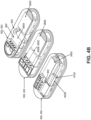
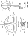
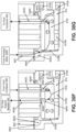
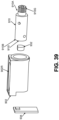
- Fig. 3A illustrates generally spheroid or ellipsoid shaped bulb pumps 600H, 600F.
- Figs. 3B-3D shows generally T-shaped bulb pumps 600H, 600F, with the forefoot bulb pump 600F oriented more under the metatarsal head support areas of the sole structure 104 (as opposed to more in the toe support areas in Fig. 3A).
- Fig. 3B shows general potential locations for the pumps 600H, 600F in a sole structure 104.
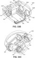
- Fig. 3C shows an overall arrangement of the pumps 600H, 600F and their connecting lines, and
- Fig. 3D shows a closer view of a T-shaped bulb pump (e.g., 600H in this example), which may be in fluid communication with a forefoot pump 600F, a fluid distributor 500, or another footwear component.
- a T-shaped bulb pump e.g., 600H in this example
- the bulb pumps 600H, 600F may be sandwiched between sole components, such as between the lower sole component 104L and one or more outsole components 104.
- a forefoot outsole component may be provided to engage forefoot pump 600F and a separate heel outsole component may be provided to engage the heel pump.
- the bulb pump 600H and/or 600F will compress between the sole components under the applied force (the user's weight), thereby forcing fluid out of the bulb pump 600H and/or 600F outlet 600HO, 600FO and moving fluid from the pumps 600H, 600F to the fluid distributor 500.
- One-way valves may be provided to prevent backward fluid flow through the pump(s) 600F, 600H.
- the bulb pump(s) 600H, 600F may be attached to and/or located between flat or smoothly curved foam, bladder, outsole, or other sole component surfaces (e.g., to increase pumping volume per step). If necessary, however, the bulb pump(s) 600H, 600F may be at least partially received within a recess in at least one of the components to which it is attached (e.g., within a recess in one or more of a foam, bladder, outsole, or other sole component surface).
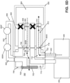
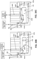
- the fluid distributor 500 of this example serves as a central hub to which fluid comes from various starting locations (e.g., the external or ambient environment 150 or other fluid source; the pump(s) 600H, 600F; the foot support bladder 200; or the fluid container 400) and from which the fluid leaves to go to various destinations (e.g., the external or ambient environment 150; the foot support bladder 200; or the fluid container 400).
- the fluid distributor 500 of this example includes a connector 700, a manifold 800, and a fluid transfer system 900.
- Various fluid lines connect fluid distributor 500 with the various fluid starting locations and destinations. These fluid lines are described in more detail in conjunction with the various operational states shown in Figs. 5A-5F .
- the large "X's" in Figs. 5A-5F show fluid paths of the fluid transfer system 900 that may be closed off in that operational state. When needed, these fluid paths may be closed off in any desired manner, e.g., by a check valve or one-way valve (e.g., in the fluid line 606 from the pump(s) 600H, 600F), due to features of the valve stem, due to solenoid valve configurational features, etc.
- the filter 702 may have an area of at least 50 mm 2 , an area between 50 mm 2 to 100 mm 2 , an area between 50 mm 2 to 150 mm 2 , and area between 25 mm 2 to 250 mm 2 , or other desired area. Any desired type of filter media, filter construction, and/or filter material may be used, such as a flat sheet of filter material, a flat screen, etc.
- the filter 702 may provide a relatively large exterior area of the connector 700, potentially providing at least a majority of the surface area of one exposed outer surface of the connector 702, e.g., as shown in Figs. 5A-5E , 11A , 12A , and 13B .
- a filter may be provided at other locations within the connector 700 and/or within the fluid flow paths (e.g., somewhere before inlet to pump(s) 600H, 600F, extending at least partially inside the connector 700 body, extending at least partially inside a dedicated fluid path 702P, etc.).
- fluid travels through the connector body (e.g., through fluid path 702P or an open interior space 710 inside connector 700) and out through port 702O.
- a dedicated fluid path 702P e.g., a closed fluid tube
- the open interior space 710 may be considered as at least part of fluid path 702P through the connector 700.
- connector inlet port 704 fluid flows through the connector 700 via a connector fluid path 704P (also called a “fourth connector fluid path” herein), to a connector outlet port 704O (also called a “fourth fluid path connector” herein), and to an incoming fluid port 800A of the manifold 800. Fluid flows from the incoming fluid port 800A, through a fluid inlet path 802 in the manifold 800, through a fluid inlet port 800I and into the fluid transfer system 900.
- a connector fluid path 704P also called a "fourth connector fluid path” herein
- connector outlet port 704O also called a "fourth fluid path connector” herein
- fluid leaves the fluid transfer system 900 passes through a first manifold port 804, through a first manifold fluid flow path 806 defined in the manifold 800, through another manifold port 800B, to a first fluid path connector (or port) 706 of the connector 700, through the first connector fluid path 708, and optionally to the external environment 150. Additionally or alternatively, fluid passing through first fluid path connector 706 may empty into the interior space 710 within the connector 700 (and thus become part of the external environment) and/or be available for another pump cycle.
- a selectively operable fluid path could be provided from the pump(s) 600H, 600F directly to the external environment 150.
- the pump(s) 600H, 600F could be deactivated.
- Fig. 5B shows an operational state in which fluid moves into the fluid distributor 500 from the external environment 150 and is transferred to the foot support bladder 200. Again, the fluid flow in this operational state is shown by the thick, arrowed, broken lines.
- This operational state may be used to increase pressure in the foot support bladder 200, e.g., for a firmer feel and/or more intense activities (such as running).
- incoming fluid from the external environment 150 e.g., air
- a softer feel or for less intense activities such as walking or casual wear
- An example of this operational state is shown in Fig. 5C , and the fluid flow is shown by the thick, arrowed, broken lines.
- fluid leaves the foot support bladder 200 enters foot support fluid line 202, passes into the second connector fluid path 714 via connector port 720 and to second fluid path connector 712 of the connector 700.
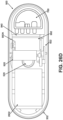
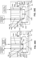
- FIG. 5D Another potential operational state for fluid distributor 500 and foot support systems in accordance with some examples of this technology is shown in Fig. 5D .
- fluid is transferred from the fluid container 400 to the external environment 150, e.g., to reduce fluid pressure in the fluid container 400.
- the fluid flow of this operational state is shown by the thick, arrowed, broken lines.
- fluid leaves the fluid container 400, enters a fluid container fluid line 402, passes into a third connector fluid path 716 via connector port 722 and to a third fluid path connector (or port) 718 of the connector 700.
- fluid passes through manifold port 800D and into a third manifold fluid flow path 812 defined in the manifold 800, through a third manifold port 814 and into the fluid transfer system 900.
- the fluid is discharged to the external environment 150. This occurs by the fluid leaving the fluid transfer system 900, passing through the first manifold port 804, through the first manifold fluid flow path 806 defined in the manifold 800, through manifold port 800B to the first fluid path connector (or port) 706 of the connector 700, and through the first connector fluid path 708 to the external environment 150 (which may constitute an interior space 710 within the connector 700).
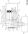
- fluid distributors 500 and foot support systems it may be desired to use the on-board fluid container 400 to adjust (and in this example, increase) fluid pressure in the foot support bladder 200. This may allow more predictable or controlled fluid transfer over time as less influence in fluid flow from pressure spikes due to foot contact with the ground may be experienced.
- An example of this operational state is shown in Fig. 5E . In this operational state, fluid leaves the fluid container 400, enters the fluid container fluid line 402, passes into the third connector fluid path 716 via connector port 722 and to the third fluid path connector 718 of the connector 700.
- fluid passes through manifold port 800D into the third manifold fluid flow path 812 defined in the manifold 800, through the third manifold port 814 and into the fluid transfer system 900. From here, in this example system and operational state, the fluid is transferred to the foot support bladder 200. This occurs by the fluid leaving the fluid transfer system 900, passing through the second manifold port 808, through the second manifold fluid flow path 810 defined in the manifold 800, through manifold port 800C to the second fluid path connector 712 of the connector 700, through the second connector fluid path 714 to connector port 720, into foot support fluid line 202, and into the foot support bladder 200.
- Fig. 5F shows an example operational state for adding fluid to the fluid container 400 (e.g., to increase fluid volume and/or pressure in the fluid container 400).
- incoming fluid from the external environment 150 e.g., air
- incoming fluid from the external environment 150 enters the connector 700 via filter 702 and connector inlet 702I.
- fluid travels through the connector body to connector outlet port 702O and to a fluid path 604 that takes the fluid to the pump system (pump(s) 600H, 600F).
- pump(s) 600H, 600F From the pump(s) 600H, 600F, fluid travels down a fluid line 606 back to an inlet port 704 of the connector 700.
- fluid leaves the fluid transfer system 900 passes through the third manifold port 814, through the third manifold fluid flow path 812 defined in the manifold 800, through manifold port 800D, to the third fluid path connector (or port) 718 of the connector 700, through the third connector fluid path 716, through connector port 722, into the fluid container fluid line 402, and into the fluid container 400.
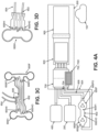
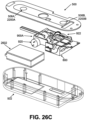
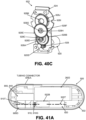
- Some portions or all of the fluid distributor 500 may be included in or engaged with a housing 502 (e.g., including a frame 504 and a cap 506). See Figs. 2A and 2B .
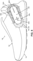
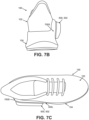
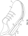
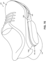
- the housing 502 may be mounted to the sole structure 104 and/or to the footwear upper 102. When mounted on a side surface of an article of footwear 100, e.g., as shown in Figs.
- the fluid distributor 500 may be located at a lateral, heel area of the upper 102 and/or sole structure 104, e.g., to help prevent undesired contact between the user's feet.
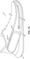
- the example footwear 100 structures of Figs. 6-7E show the sole structure 104 including an upwardly extending base surface 700S that provides a base for attachment of the fluid distributor 500.
- the base surface 700S may form part of lateral cage component 300L described above in conjunction with Fig. 2B .
- Fluid lines e.g., from the foot support bladder 200, from the fluid container 400, from the fluid source (e.g., pump(s) 600H, 600F), and/or from the external environment 150) may extend through this base surface 700S and/or otherwise may be exposed at this base surface 700S for engagement with the fluid distributor 500, as will be described in more detail below.
- the cap 506 of the fluid distributor 500 may include an input system, e.g., one or more switches (506A and 506B shown in Fig. 6 ). These switches 506A and 506B can function as user inputs, e.g., to allow a user to manually increase (switch 506A) or decrease (switch 506B) air pressure in the foot support bladder 200. User interaction with switches 506A and 506B, when present, may activate the fluid distributor 500 and fluid transfer system 900 to move fluid as described with respect to one or more of the operational states above. Fig.
- the fluid distributor 500 may include one or more lights 506L (e.g., one or more LED's (e.g., 12) around a perimeter of its housing 502) within a light guide. These light(s) 506L may be decorative and/or may allow color variations of the displayed light.
- lights 506L e.g., one or more LED's (e.g., 12) around a perimeter of its housing 502
- These light(s) 506L may be decorative and/or may allow color variations of the displayed light.
- the light(s) 506L may provide information, e.g., relating to one or more of: (a) an "on" or “off' status of the fluid distributor 500 (e.g., light(s) 506L on means powered, light(s) 506L off means unpowered); (b) foot support pressure and/or other pressure status information of the footwear 100 (e.g., depending on light color and/or flashing indicating maximum pressure, minimum pressure, intermediate pressure(s), etc.); (c) system reset status; (d) factory reset status; (e) powering on, powering off, and/or reboot status; (f) pressure adjustment in progress; (g) an error condition; (h) battery charging status; (i) remaining battery charge status; (j) successful and/or unsuccessful electronic communication status information with the other shoe and/or a mobile computing device (BTLE confirmation status); (k) data download, upload, and/or software update progress or status information; (1) operational state identifying and/or status information; etc.
- a second fluid line 606 takes fluid from the pump(s) (600H, 600F) back to the connector 700 so it can be introduced into the manifold 800 and fluid transfer system 900 under increased pressure from the pump(s) 600H, 600F.
- a third fluid line 202 extends to and is in fluid communication with the foot support bladder 200. This fluid line 202 is used to move fluid into the foot support bladder 200 from the fluid distributor 500 and out of the foot support bladder 200 into the fluid distributor 500.
- a fourth fluid line 402 extends to and is in fluid communication with the fluid container 400. This fluid line 402 is used to move fluid into the fluid container 400 from the fluid distributor 500 and out of the fluid container 400 into the fluid distributor 500. Notably, as shown in Figs.
- Figs. 12A-12C further illustrate the connector 700-to-housing 750 connection of Figs. 11A and 11B to highlight some additional potential features.
- a sealing system 760 is provided between the ports 800A, 800B, 800C, 800D of manifold 800 and the ports, 704O, 706, 712, 718, respectively, of connector 700.
- the sealing system 760 includes female engagement parts (e.g., channels 760A, 760B, 760C, 760D) that fit around male engagement parts (e.g., tubular structures forming the outer surfaces of ports 800A, 800B, 800C, 800D) to sealingly engage the manifold 800 with the connector 700.
- the other ends of channels 760A, 760B, 760C, 760D may sealingly engage the connector 700 and align with (and/or form) connector ports 704O, 706, 712, 718.
- these fluid lines include: (a) fluid line 604 extending from the connector inlet 702I to the pump(s) 600H, 600F, (b) fluid line 606 extending from the pump(s) 600H, 600F back to the connector 700, (c) fluid line 202 extending between the foot support bladder 200 and the connector 700, and (d) fluid line 402 extending between the fluid container 400 and the connector 700.
- Fluid lines 604, 606, 202, 402 may be engaged with their respective connector ports 702O, 704, 720, 722 in any desired manner, including via use of adhesives, mechanical connectors, friction fits, engaged male/female connectors, etc.
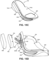
- Fig. 15C shows the final assembled sole component 104 of this example.
- the sole component 104 may be engaged with an upper 102 to form the overall article of footwear 100 (before or after the housing 750 is engaged in the frame 504).
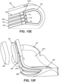
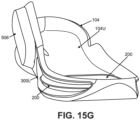
- Figs. 15D-15G illustrate assembly of a connection in which the connector 700 is formed as part of the manifold 800 structure and included in housing 750 prior to assembly.
- the fluid lines from the various footwear component parts are brought to and engaged with connector 700 ports located at the interior side of housing 750.
- these fluid lines include: (a) fluid line 604 extending from the connector inlet 702I to the pump(s) 600H, 600F, (b) fluid line 606 extending from the pump(s) 600H, 600F back to the connector 700, (c) fluid line 202 extending between the foot support bladder 200 and the connector 700, and (d) fluid line 402 extending between the fluid container 400 and the connector 700.
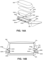
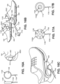
- FIG. 16A shows charge puck 1102 engagable at a rear heel area of the shoe 100.
- Figs. 16B and 16C show charge puck 1102 engaged at a side (e.g., lateral, heel side) of shoe 100.
- Fig. 16B further illustrates a pair of charge pucks 1102 including individual power lines 1104 engaged with a connector 1108A that extends to a single power line 1108 coupled with AC adapter 1110.
- some examples of this technology may use non-rechargeable batteries.
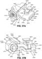
- Figs. 17A and 17B illustrate other examples of charge pucks 1102A and 1102B that may be used in some examples of this technology.
- Charge puck 1102A of Fig. 17A includes plural magnets 1106 arranged around an annular transmitter coil 1112 to magnetically engage charge puck 1102A with the charging station 502C magnet.
- Charge puck 1102B of Fig. 17B includes a central magnet 1106 that has an annular transmitter coil 1112 arranged around it.
- Figs. 19B and 19C show the charging system 1900 parts for storage or travel, both without the AC power adapter 1910 ( Fig. 19B ) and with the AC power adapter 1910 ( Fig. 19C ). While other options are possible, as shown in these figures, power wire 1908 may terminate at a USB connector component 1912 and the AC power adapter 1910 may include a port for receiving the USB connector component 1912. Further, as shown in Fig. 19D , in this system, the power wire 1904 engages the body of the puck 1902L, 1902R through the side surface 1902S of the puck 1902L, 1902R.
- the connector 1956 may distribute power to the two separate wires 1954, one going to each charging connector 1952L, 1952R.
- Fig. 19E shows the charging connectors 1952L, 1952R engaged with the fluid distributor 500 on the lateral sides of each of the left shoe 100L and the right shoe 100R, respectively.
- Figs. 19F and 19G show the charging system 1950 parts for storage or travel, both without the AC power adapter 1910 ( Fig. 19F ) and with the AC power adapter 1910 ( Fig. 19G ).
- the charging system 1950 of Figs. 19E-19G may include a magnet or magnetic attracting material 1914 in the AC power adapter 1910, e.g., in the same manner described above with respect to Figs. 19B and 19C .
- Figs. 19E and 19F further show that intermediate connector 1956 may releasably connect to wires 1954, e.g., by end 1956A from wire 1958 engaging ends 1954A of wires 1954.
- any desired type of releasable electrical connection may be used, including sockets, plugs, clips, and/or other releasable connections as are known and used in the relevant arts.
- Fig. 19F further shows charging connectors 1952L, 1952R directly and magnetically engaged with one another for storage or travel by the magnets included in them. Additionally, the wires 1954, 1958 may wrap around handles 1960 in a compact manner for storage or travel, e.g., as shown in Fig. 19F .
- the button is a capacitive type button (e.g., including a capacitive sense electrode of structure known and used in art relevant arts).
- This example user interface switch or system 2200 is unlocked by a swipe action of the button, and changes in pressure are input by a touch action on either side of the center (e.g., touch the right side 506B to decrease pressure by a predetermined amount, touch the left side 506A left to increase pressure by a predetermined amount).
- buttons 2200A, 2200B are adjacent one another on the same side of the button and the same side of the keep-out zone.
- the buttons 2200A, 2200B are separated from one another by the keep-out zone and are on different ends of the button. Buttons having a "button press” or “press” label in Fig. 22A may constitute physical switch type button activators.
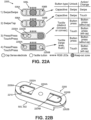
- Figs. 22B-22E provide various views of an example button construction for the "touch/press" option of Example 4 of Fig. 22A.
- Fig. 22B shows flex areas 2202A, 2202B corresponding to the physical tactile button locations 2200A, 2200B overmolded by a rubber or other polymer (e.g., silicone or other elastomer) composition (or formed in a two-shot molding process).
- Grooves 2204A and 2204B extending partially through the overmold material 2210 around the button actuator area create a thinner layer of rubber or other material (e.g., elastomer) to better enable flexion when buttons 2200A, 2200B are pushed.
- These grooves 2204A, 2204B also may provide the tactile feel features described above.
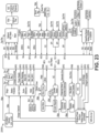
- Fig. 23 provides an electrical block diagram 2300 of components in some example fluid distributors 500, fluid flow control systems, sole structures 104, and/or articles of footwear 100 in accordance with aspects of this technology. While Fig. 23 illustrates several components and systems incorporated into fluid distributors 500, fluid flow control systems, sole structures 104, and/or articles of footwear 100 in accordance with aspects of this technology, any desired subset or combination of these components and systems may be used in some examples of this technology. More of these components and systems identified in Fig. 23 will be described in more detail below.
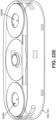
- Fig. 24 illustrates an example layout of various components within a housing 502 (and/or on a circuit board) of a fluid distributor 500 in accordance with at least some examples of this technology.
- Fig. 24 shows various lights 506L arranged around the exterior perimeter of the housing 502, as mentioned above.
- a light driver 2410 (“LED driver") is provided to control operation of the lights 506L, which may constitute a 12 RGB LED ring of lights (e.g., under programmed/programmable control).
- LED driver LED driver
- this system may include an antenna 2402 (e.g., a Bluetooth Low Energy (“BLE”) antenna) for receiving wireless input (such as from a computing device, mobile computing device (e.g., a "smart phone")); for receiving electronic information from the other shoe of a pair; for receiving electronic information from apparel and/or another source; for receiving electronic information from other sensors (e.g., on-board shoe sensor(s), apparel based sensors, sensors included as a speed and/or distance monitor in an external computing device, etc.); etc.
- a microcontroller 2404 (“MCU”) is provided to run the software and hardware needed to perform the functions described above and those described in more detail below (and optionally any other functions and/or hardware that may be provided).
- IMU's 2406 also may be provided, such as accelerometers (“ACC”), magnetometers (“MAG”), etc., to detect user motion in the article of footwear 100. Data from such inertial measurement units or other available sensors may be used to automatically control and/or change pressure settings in the foot support bladder 200 and/or fluid container 400 in one or both shoes.
- a motor driver 2408 is present in this illustrated example, e.g., to control operation of any motor(s) in the fluid distributor 500 (e.g., as will be described in more detail below).
- the seemingly "open space” within the housing 502 may be filled, at least in part, with some or all of a manifold 800 and fluid transfer system 900, the rechargeable battery, and/or other desired components.
- the central controller 2500 may be included as part of one shoe (e.g., within housing 502 of fluid distributor 500 for that shoe), and it may communicate with that shoe via a wired or wireless connection.
- the shoe including the central controller 2500 may communicate with the other shoe, e.g., via a wireless connection as mentioned above.
- the central controller 2500 may be provided as part of a computing device, e.g., a mobile computing device, such as an application program operating on a smartphone.
- pressure change information may be provided via an external computing device (e.g., the smartphone) and transmitted to one or both shoes, e.g., via antenna 2402 in housing 502.
- fluid transfer systems 900 Various examples of structures and operations of fluid transfer systems 900 are described in more detail in the sections that follow. Some aspects of fluid transfer systems 900 in accordance with this technology relate to valve stems within a valve housing to open and close various fluid pathways through a manifold 800. Other aspects of fluid transfer systems 900 in accordance with this technology relate to solenoid based systems that selectively open and close to control fluid flow through a manifold 800.
- the valve stem 910 may place the fluid transfer system 900A in two or more operational states depending on the position of the valve stem 910 with respect to the housing body 902. Movement of the valve stem 910 changes positioning of the through holes 910H through the perimeter wall 910W of the valve stem 910 and allows different holes 910H to align with the sealing connector 840 ports 840A, 840B, 840C.
- the valve stem 910 may be moved, e.g., rotated, under control of a microprocessor controlling a motor 920.
- Figs. 30A-30G provide additional details about various operational states that may be provided and used in fluid distributor 500, foot support systems, sole structures 104, and articles of footwear 100 including fluid transfer system 900A in accordance with aspects of this technology.
- Operational state 2 (e.g., with the valve stem 910 rotated 60 degrees clockwise from operational state 1) is a "pumping" state for moving fluid from the pump(s) (or other fluid source) to the foot support bladder 200.
- fluid pumped during a step passes through the system (e.g., from pump(s) 600H, 600F, through manifold 800, through fluid transfer system 900A, back through manifold 800) and into the foot support bladder 200. See Fig. 30C .
- This operational state may be used to quickly and/or directly increase fluid pressure in the foot support bladder 200 (e.g., a foot support bladder 200 "inflate" configuration).
- the system can start to "learn” (e.g., identify patterns) how a user moves (e.g., tends to run or exercise at certain time(s) of the day, tends to run on specific types of surfaces, tends to run at varying speeds (e.g., based on a workout program), etc.) and, based on this information, predict and apply changes in operational states to match predicted changes in motion.
- pressure changes to the foot support system may better align to changes in the user's motion in "real time” or seemingly real time.
- automatic (or system generated) operational state changes can be aligned to desired changes in movement received from the digital coaching system to match desired performance or to mitigate injury risk, thereby also being a communication system to the user.
- a specific fluid distributor 500, foot support system, sole structure 104, and/or article of footwear 100 does not include all of these parts (e.g., no separate connector 700, no sealing block 840, one or fewer foot activated pumps 600H, 600F, etc.), then the fluid flow through those parts would not be present in the fluid flow path described above.
- the holes 910H that align with the ports 840A, 840B, 840C, 804, 808, 814 in the individual operational states of the valve stem 910 are circumferentially offset from one another so that only the one or more holes needed to make the desired fluid flow connection and pathway align with the correct ports.
- the through holes needed to make the fluid flow connection may: (a) align along the axial length and direction of the valve stem 910, and/or (b) extend in parallel through the perimeter wall 910W.
- the valve stem 910 is rotationally positioned such that the central axes of through holes 940G, 940H are offset from the central axes of seal ports 840C, 840B, respectively, by 10 rotational degrees.
- the offset amount results in a fluid flow rate reduction to about 41% of the full flow rate when the holes and parts are fully aligned.
- the valve stem 910 is rotationally positioned such that the central axes of through holes 940G, 940H are offset from the central axes of seal ports 840C, 840B, respectively, by 15 rotational degrees.
- This example results in a fluid flow rate reduction to about 1% of the full flow rate when the holes and parts are fully aligned. Only a small sliver of holes 940G, 940H are visible in Fig. 31D .
- the reduced flow rates can be used, for example, to make minor or slow pressure adjustments, e.g., to the foot support bladder 200 and/or the fluid container 400, to fine-tune to a desired pressure, etc.
- Figs. 32A and 32B provide a perspective view and cross-sectional view, respectively, of the combined manifold 800 (rigid plastic) and cartridge style sealing connector 840 of one example.
- this example manifold 800 has: (a) four ports 800A, 800B, 800C, 800D (optionally aligned) at one surface 800E, (b) fluid inlet port 800I, (c) first port 804, second port 808, and third port 814 at another surface 800F (e.g., the opposite surface from surface 800E), e.g., with ports 804, 808, 814 aligned, and (d) four fluid flow paths 802, 806, 810, 812 through the manifold body 820 (optionally aligned and/or extending in parallel).
- Figs. 32A and 32B show end surfaces 800E and 800F at opposite sides of the manifold body 820 and fluid flow paths 806, 810, 812 extending straight through the manifold body 820 from surface 800E to surface 800F
- one or more of the fluid flow paths 802, 806, 810, 812 may be curved and/or angled such that one or more ports 800A, 800B, 800C, 800D at one end of the fluid flow paths are not located on an opposite surface from the corresponding port 800I, 804, 808, 814 at the other end of the fluid flow path.
- Any desired arrangement of ports and/or path shapes may be used. The illustrated arrangement helps maintain the manifold 800 at a relatively compact size and shape.
- Ports 804, 808, 814 of this example are located within a recess 800R defined in the manifold body 820.
- the sealing connector 840 is received in that recess 800R and is secured by chemical bonds or opposing face seals (and optionally not just perimeter seals).
- the sealing connector 840 of this example includes: (a) three ports 840A, 840B, 840C at one surface 840E and (b) three sealed channels 842A, 842B, 842C extending from ports 840A, 840B, 840C to openings at surface 840F (the openings in the sealing connector at surface 840F also may be considered "ports" of the sealing connector 840).
- FIG. 840F of sealing connector 840 abuts against surface 800F of manifold 800, and sealed channels 842A, 842B, 842C align with manifold 800 fluid flow paths 806, 810, 812, respectively, to place the sealing connector 840 and manifold 800 in fluid communication. While Figs. 32A and 32B show end surfaces 840E and 840F at opposite sides of the sealing connector 840 and sealed channels 842A, 842B, 842C extending straight through the sealing connector 840 from surface 840E to surface 840F, other arrangements are possible.
- the example structures shown in Figs. 29-32B include sealing connector 840 having three sealed channels 842A, 842B, 842C in fluid communication with three fluid flow paths 806, 810, 812 in manifold 800.
- the fluid inlet path 802 through manifold 800 does not pass through the sealing connector 840. Rather, it directly connects with fluid intake path 902A of housing 900 (housing 900 not shown in Figs. 32A and 32B ).
- fluid intake path 902A of housing 900 housing 900 not shown in Figs. 32A and 32B .
- the sealing connector 840 may include four ports 840A, 840B, 840C, 840D at one surface 840E and (b) four sealed channels 842A, 842B, 842C, 840D extending from ports 840A, 840B, 840C, 840D to openings at surface 840F (the openings in the sealing connector at surface 840F also may be considered "ports").
- the additional port 840D and sealed channel 842D of the example of Fig. 32C may engage with fluid inlet port 800I and flow in fluid communication with fluid inlet path 802.
- the manifold 800 recess 800R in such a structure could be increased in size and/or changed in shape to extend to include fluid inlet port 800I and to accommodate the additional port 840D, sealed channel 842D, and fluid communication with fluid inlet path 802.
- the additional port 840D and sealed channel 842D of the example of Fig. 32C may engage with a fluid passageway in fluid communication with another component of the overall foot support system, such as another foot support bladder (if present), another fluid container (if present), etc.
- sealing connector ports 840A, 840B, 840C directly engage the outer surface of the perimeter wall 910W of the valve stem 910.
- Valve stem 910 moves (e.g., rotates) to place the fluid transfer system 900A of this example into the various operational states.
- Fig. 32C shows features of sealing connector ports 840A, 840B, 840C (and 840D, in this example) that may assist in maintaining a sealed connection between sealing connector 840 and the valve stem 910 perimeter wall 910W.
- the arched outer surface shapes 840S of this example have two opposed curve inflection points (e.g., local maxima) 844A on opposite sides of the ports 840A, 840B, 840C in the rotational direction of the valve stem 910 and two opposed curve inflection points (e.g., local minima) 844B on opposite sides of the ports 840A, 840B, 840C in the axial direction of the valve stem 910.
- the arched outer surface shapes 840S of this example are raised up from base surface 840E to give the arched outer surface shapes 840S somewhat of a "fishlips" type appearance. These shapes correspond to and maintain better contact with the curved surface of perimeter wall 910W.
- pressure sensors useful in accordance with at least some aspects of this technology will have one or more of: (a) a sensing pressure range from atmospheric pressure to at least +40psi (e.g., 14.7 to 54.7 psi); (b) a small size (e.g., 5 mm by 5 mm or less), (c) a relative accuracy or error level of less than 0.15 psi (including non-linearity, hysteresis, and non-repeatability), (d) an absolute accuracy of less than 1 psi, (e) a digital output with on-board temperature compensation, and/or (f) an update rate of 50 Hz or more.
- a sensing pressure range from atmospheric pressure to at least +40psi (e.g., 14.7 to 54.7 psi); (b) a small size (e.g., 5 mm by 5 mm or less), (c) a relative accuracy or error level of less than 0.15 psi (including non-linearity,
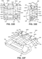
- Figs. 33B-33F provide various views of another example combined valve housing 902, valve stem, 910, sealing block 840, and manifold 800 in which two pressure sensors 850A and 850B (e.g., of the types described above) are provided.
- the manifold body 820 and the valve housing 902 are formed as a one-piece construction. Sealing block 840 and valve stem 910 may be inserted into this combined manifold body 820 and the valve housing 902 structure, e.g., at the open end where encoder board or sensor 934 later may be mounted.
- the various parts shown in Figs. 33B-33F use the same reference numbers used above for the same or similar parts (and thus much of the overlapping or redundant description has been omitted).
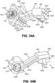
- FIGs. 34A and 34B show an example structure having one or more pressure sensor mounts, e.g., tubes (two tubes 854A, 854B shown in Figs. 34A and 34B ) that define a recess 840R for mounting a pressure sensor (e.g., 850A, 850B), as part of a sealing connector 840.
- a pressure sensor e.g., 850A, 850B
- the sealing connector 840 of this example includes: (a) a base surface 840E including the ports 840A, 840B, 840C, 840D; (b) an outlet surface 840F including openings (or ports) 846A, 846B, 846C, 846D for engaging ports 800I, 804, 808, 814 of manifold 800 (manifold not shown in Figs. 34A and 34B ); and (c) sealed fluid channels 842A, 842B, 842C, 842D extending between surfaces 840E and 840F.
- Surface 840F is provided at the free end of a block 848 of material in which the pressure sensor tube(s) (e.g., 854A, 854B) is/are defined and to which the pressure sensor(s) (e.g., 850A, 850B) is/are mounted.
- the tubular structures defining the sealed fluid channels 842A, 842B, 842C, 842D may be flexible so that the block 848 can be moved with respect to the connection to the housing 902 at surface 840E, e.g., to ease assembly, provide tolerance, etc.
- the pressure sensor tube(s) may be in fluid communication with any of sealed fluid channels 842A, 842B, 842C, 842D extending between surfaces 840E and 840F, e.g., via open channels as described above in conjunction with Fig. 33A , to measure pressure in any of channels 842A, 842B, 842C, 842D and/or devices in fluid communication with them.
- pressure sensors 850A, 850B will provide pressure readings in foot support bladder 200 and fluid container 400.
- pressure sensor mounts in a manifold body 820 may have tubular structures of the types shown in Figs. 34A-34B (as well as pressure sensor mounts like those shown in Figs. 35A-37B ).
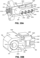
- Figs. 35A and 35B illustrate another example in which pressure sensor(s) (e.g., 850A, 850B) is/are engaged with sealing connector 840.
- this sealing connector 840 is more like that shown in Fig. 32C , e.g., without flexible and/or individually apparent sealed fluid channels 842A, 842B, 842C, 842D.
- the sealing connector 840 of this example is more of a block 848 of material through which sealed fluid channels 842A, 842B, 842C, 842D are formed. While shown in fluid communication with sealed channels 842B, 842D in Figs.
- the junction of surface 840E with housing 902 is sealed by one or more O-rings, gaskets, and/or other types of seals 858A, and the junctions of ports 840A, 840B, 840C, 840D with perimeter wall 910W of valve stem 910 are sealed with O-rings, gaskets, and/or other types of seals 858B (only one seal 858B shown in Figs. 36A-36B ).
- the sealing connector 840 of this example is a block 848 of material through which sealed fluid channels 842A, 842B, 842C, 842D are formed. While shown in fluid communication with sealed channels 842B, 842D in Figs.
- recess(es) e.g., 856A, 856B
- pressure sensor(s) e.g., 850A, 850B
- any of sealed fluid channels 842A, 842B, 842C, 842D extending between surfaces 840E and 840F, e.g., to measure pressure in any of channels 842A, 842B, 842C, 842D and/or devices in fluid communication with them.
- pressure sensors 850A, 850B will provide pressure readings in foot support bladder 200 and fluid container 400.
- Pressure sensors 850A, 850B are engaged with sealing connector 840 within the recesses 856A, 856B by O-rings 852 (or gaskets or other appropriate seals).
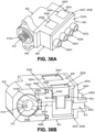
- Figs. 36A-36B illustrate sealing connector 840 engaged with a manifold 800.
- the manifold 800 of this example is relatively short as compared to others described above.
- the manifold 800 includes a base 820A having a base surface 820B to engage surface 840F of the sealing connector 840 and four manifold ports 800A, 800B, 800C, 800D projecting outward from the base 820A.
- These manifold ports 800A, 800B, 800C, 800D may engage a connector 700 as described above and/or may directly engage fluid tubes, e.g., coming from the fluid supply (e.g., pumps 600H, 600F), external environment 150, foot support bladder 200, and fluid container 400 (e.g., if no connector 700 is present).
- the fluid supply e.g., pumps 600H, 600F
- external environment 150 e.g., foot support bladder 200
- fluid container 400 e.g., if no connector 700 is present.
- the rigid part 840H forms the bottom half of a portion of the sealed channels 842A, 842B, 842C, 842D between the pressure sensors 850A, 850B and the valve housing 902.
- the flexible part 840G and the rigid part 840H cooperate to define the portion of the sealed channels 842A, 842B, 842C, 842D between the pressure sensors 850A, 850B and the valve housing 902.
- the rigid part 840H also defines a portion of the sealed channels 842A, 842B, 842C, 842D immediately opposite the pressure sensor(s) 850A, 850B across the channels 842A-842D.
- This two part sealing connector 840 may provide some flexibility, e.g., for ease of assembly, while still providing a solid overall structure.
- valve housing 902 may be engaged with a rigid manifold 800 component that includes recess 800R into which a sealing connector 840 is inserted.
- the valve housing 902 and the manifold 800 may be joined together using any desired technique(s), such as mechanical connectors, adhesives, ultrasonic welding, laser welding, and/or other fusing techniques, etc.
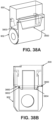
- Figs. 38A and 38B illustrate one example of such a connection (although similar connections may be used, if desired, to engage a sealing connector 840 with a valve housing 902, e.g., as shown in Figs. 34A-37B ).
- valve housing 902 and the manifold 800 of this example snap together mechanically to hold the parts together.
- flat faces 3800 are provided on each of the valve housing 902 and the manifold 800 (although grooved surfaces could be provided, if desired), e.g., around the various interfacing side surfaces.
- adhesive e.g., a liquid dispensed adhesive
- Small chamfers 3802 may be included in one or both of interfacing surfaces 3800 of valve housing 902 and the manifold 800, e.g., to provide room for any excess adhesive to be squeezed out from the interfacing surfaces 3800.
- Overlapping lips 3804 also may be provided between the parts, e.g., inward from the flat faces 3800.
- Fluid transfer systems 900A in accordance with at least some examples of this technology include one or more sensors for determining a position (e.g., a rotational position) of the valve stem 910 with respect to the valve housing 902 (and/or with respect to any one of more of the sealing connector 840 and/or manifold 800 (when either or both are present)).
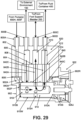
- Fig. 39 illustrates an example fluid transfer system 900A in which a position sensor 930 is provided.
- Position sensing may be performed, in at least some examples of this technology, by an encoding system capable of measuring an absolute rotational position, or a relative positioning sensor with an additional index channel that denotes a specific absolute rotational position.
- the position sensor constitutes a magnetic encoder system 930 (e.g., an on-axis magnetic encoder system, an off-axis magnetic encoder system, etc.) including an encoder magnet 932 and a sensor 934.
- This magnetic encoder system 930 is an absolute position sensor.
- the encoder magnet 932 is engaged with the movable (e.g., rotatable) valve stem 910 (e.g., within internal chamber 910I at the second end 910B) and rotates with the valve stem 910. Changes in magnetic field strength measured at the sensor 934 indicate the position of the magnet 932 (and thus the position of the valve stem 910) with respect to the housing 902 or other component.
- the relative position of the magnet 932 (and valve stem 910) with respect to the housing 902 or other component also determines (and/or allows determination of) the operational state of the fluid transfer system 900A as described above.
- Other types of position sensors 930 may be used without departing from at least some aspects of this technology (e.g., optical encoders, other rotational sensors, etc.).
- Magnetic encoder systems 930 provide some advantages in that they do not require physical contact of parts and they typically will be less susceptible to failure due to adhesive, lubricant, debris, or other undesired material that may work its way into internal chamber 910I.
- Optical encoders are more susceptible to failure, e.g., due to undesired material potentially masking or blocking an optical source or optical detector.
- Magnetic encoder systems 930 as well as other positional sensor systems are known and commercially available.
- the small gear 928C of the first intermediate gear cluster 928B engages a large outer gear 928E of a second intermediate gear cluster 928F.
- Large outer gear 928E of second intermediate gear cluster 928F is mounted on a common rotary pin 928G (e.g., a steel pin) with a smaller gear 928H of the second intermediate gear cluster 928F.
- the smaller gear 928H of the second intermediate gear cluster 928F engages an outer geartrain 928I of output gear 928J.
- the central opening 928K of output gear 928J includes an inner geartrain that engages the geared end 910G of valve stem 910.
- cup seals 910S, O-rings, gaskets, or other sealing devices may be provided at the first end 910A of valve stem 910 to prevent fluid from leaking out of the housing 902.
- a nose pin 928L secures the output gear 928J and its associate components with the frame 922.
- Typical planetary transmissions 922B include a central "sun gear” (e.g., driven by motor 920 shaft 920S) and plural "planet gears” that rotate in a cooperative manner to transmit rotational energy from the motor to a driven shaft (e.g., valve stem 910's gear 910G). Planetary transmissions 922B of this type are known and commercially available.
- all foot support bladders in an article of footwear 100 may be filled simultaneously by fluid lines connecting the foot support bladders in series or parallel.
- two or more fluid containers 400 may be filled simultaneously in the same manners, but by branching container fluid line 402 into individual lines and/or connecting the fluid containers in series or parallel.
- valving or switching mechanisms may be provided, e.g., after fluid leaves connector 700 and enters foot support fluid line 202 and/or container fluid line 402.
- a separate fluid pathway through the connector 700, manifold 800, and sealing connector 840 may be provided for each individual foot support bladder 200 and/or fluid container 400; separate through holes 910H for the additional foot support bladder(s) and/or fluid container(s) may be provided in the valve stem 910 (e.g., axially spaced from the other through holes 910H); and additional operational states may be provided.
- an additional set of ports, fluid channels, and the like as shown to move fluid into and out of foot support bladder 200 may be provided for each additional foot support bladder in the shoe 100 and/or an additional set of ports, fluid channels, and the like as shown to move fluid into and out of fluid container 400 may be provided for each additional fluid container in the shoe.
- the input system e.g., on an external computing device, part of the "on-board" switching system 2200, etc.
- the fluid transfer system 900A described above utilizes a movable (e.g., rotatable) valve stem 910 that is movable to various positions to place the fluid distributor 500, fluid flow control system, foot support system, sole structure 104, and/or article of footwear 100 in two or more different operational states.
- Other types of fluid transfer systems 900 may be used to place such systems and components in two or more different operational states, including any two or more of the operational states described above with respect to Figs. 5A to 5F .
- the following discussion relates to solenoid based fluid transfer systems 900B in accordance with at least some aspects of this technology.
- Various types of solenoids and/or combinations of solenoids may be used in fluid transfer systems 900B in accordance with some aspects of this technology.
- Some solenoids that may be used in accordance with this technology are "latching solenoids.”
- Some latching solenoids like latching solenoid 4200 shown in Fig. 42 , include two stable states-an open state and a closed state. Such solenoids can maintain either of these stable states when no power is applied.
- Fig. 42 shows solenoid 4200 in the open state in which plunger 4202 is moved rearward to allow fluid to flow through the solenoid body 4204 between one port 4206 and the other port 4208 (in either direction). See fluid flow arrow 4212.
- spring 4210 or other biasing means forces plunger 4202 forward to close off (seal) either or both of ports 4206, 4208. In that state, fluid does not flow through the solenoid body 4204.
- Latching solenoids For latching solenoids, power is required to initiate movement of the plunger 4204 and change the solenoid 4200 from one state to another state. Typically, a short power pulse is applied to move the plunger 4202 of the solenoid 4200 from one position to another position. Latching solenoids also typically have a "normal state.” The "normal state” is the state the plunger 4200 will default to (e.g., due to biasing force on the plunger 4204) when no "latches" are activated to hold the plunger 4200 in one of the states.
- the solenoid may be "normally open” (or “NO”) in which fluid can flow through the solenoid or "normally closed (or “NC”) in which fluid cannot flow through the solenoid.
- Power may be applied to a normally open solenoid in a relatively short pulse to: (a) move the plunger from the open configuration to the closed configuration and (b) activate the latching mechanism to hold the solenoid in the closed position without continuous use of power.
- a biasing system e.g., spring
- Power may be applied to a normally closed solenoid in a relatively short pulse to: (a) move the plunger from the closed configuration to the open configuration and (b) activate the latching mechanism to hold the solenoid in the open position without continuous use of power.
- a biasing system e.g., spring
- the illustrated solenoid 4200 is a "normally closed” solenoid. If spring 4210 was moved to apply its biasing force between port 4206 and the front surface 4202S of the plunger 4202 (area A), then the solenoid would be a "normally open” solenoid.
- fluid distributors 500, fluid flow control systems, foot support systems, sole structures 104, and/or articles of footwear 100 in accordance with some examples of this technology include a fluid transfer system 900 for controlling the fluid flow direction and for opening/closing fluid pathways.
- Solenoid based fluid transfer systems 900B (as will be described in more detail below) may be used as the fluid transfer system 900 shown in Fig. 4A .
- solenoid based fluid transfer systems 900B in accordance with some aspects of this technology may use any of the features of the foot support bladder(s) 200, fluid container(s) 400, housing 502, connector 700, manifold 800, sealing connector 840, etc. described above (e.g., in conjunction with Figs. 1-41 ), except fluid transfer system(s) 900A, 900D is/are replaced with the fluid transfer systems 900B described below.
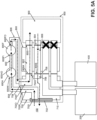
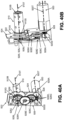
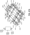
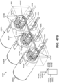
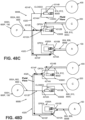
- Figs. 45-47B illustrate example physical structures of solenoid based fluid transfer systems 900B engaged with a manifold 800 and a schematic view of the fluid pathways in accordance with some aspects of this technology.
- these example fluid transfer systems 900B and fluid flow control systems include: (a) a first solenoid 4300A having a first port 4310A and a second port 4310B and switchable between an open configuration and a closed configuration; (b) a second solenoid 4300B having a first port 4312A and a second port 4312B and switchable between an open configuration and a closed configuration; and (c) a third solenoid 4300C having a first port 4314A and a second port 4314B and switchable between an open configuration and a closed configuration.
- the second port 4310B of first solenoid 4300A of this example is in fluid communication with the external environment 150, e.g., via one or more of manifold port 804, first fluid flow path 806, manifold port 800B, connector 700, etc.
- First solenoid 4300A in this example is a latching solenoid having a normally open configuration.
- the second port 4312B of second solenoid 4300B of this example is in fluid communication with a foot support bladder 200, e.g., via one or more of manifold port 808, second fluid flow path 810, manifold port 800C, connector 700, etc.
- Second solenoid 4300B in this example is a latching solenoid having a normally closed configuration.
- source e.g., pumps 600H, 600F, a compressor, etc.
- common fluid line 4920 may branch into: (a) fluid line 4910F (going to the first port 4910A of first solenoid 4900A) and (b) fluid line 4912F (going to the first port 4912A of second solenoid 4900B). Additionally, the common fluid line 4920 also is in fluid communication with a fluid source (e.g., one or more of pump(s) 600H, 600F, a compressor, the external environment 150, etc.), e.g., via one or more of manifold 800 port 800A, fluid inlet path 802, fluid inlet port 800I, connector 700, etc.
- a fluid source e.g., one or more of pump(s) 600H, 600F, a compressor, the external environment 150, etc.
- the first solenoid 4900A in the illustrated example is biased to "normally" be in the first configuration (with the biasing system closing third port 4910C).
- the second solenoid 4900B of this example is independently switchable between an open configuration (in which fluid flows through solenoid 4900B between the first port 4912A and the second port 4912B) and a closed configuration (in which fluid does not flow through solenoid 4900B).
- simultaneous selective placement of: (a) the first solenoid 4900A in one of the first configuration or the second configuration and (b) the second solenoid 4900B in one of the open configuration or the closed configuration selectively places this fluid transfer system 900C in a plurality of (e.g., two or more) operational states. Examples of these operational states are described in more detail below.
- fluid flows from the foot support bladder 200, through second manifold port 800C, through the second port 4912B of the second solenoid 4900B, through the second solenoid 4900B, through the first port 4912B of the second solenoid 4900B, through fluid line 4912F, through the common fluid line 4920, through fluid line 4910F, through the first port 4910A of the first solenoid 4900A, through the first solenoid 4900A, through the second port 4910B of the first solenoid 4900A, through manifold port 800B, and to its ultimate destination (the external environment 150 in this example).
- Fluid transfer systems 900B and 900C described above include a single foot support bladder 200 and a single fluid container 400. If desired, however, fluid transfer systems, foot support systems, fluid distributors 500, sole structures 104, and/or articles of footwear 100 in accordance with at least some aspects of this technology may include structure for supporting fluid pressure changes to more than one foot support bladder 200 and/or more than one fluid container 400.
- fluid could be introduced to all bladders simultaneously. This could be accomplished in various ways. For example, all foot support bladders may be filled simultaneously by branching fluid line 202 into individual foot support supply lines running to corresponding individual foot support bladders.
- an additional set of ports, fluid channels, solenoids, and the like as shown to move fluid into and out of foot support bladder 200 may be provided for each additional foot support bladder and/or an additional set of ports, fluid channels, solenoids, and the like as shown to move fluid into and out of fluid container 400 may be provided for each additional fluid container in the shoe.
- the input system e.g., on an external computing device, part of the "on-board" switching system 2200, etc.
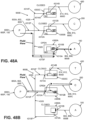
- Figs. 49A-49D schematically illustrate (as "optional") a second foot support bladder 250 in fluid transfer system 900C.
- a third solenoid 4900C is provided to transfer fluid into and out of second foot support bladder 250.
- This third solenoid 4900C includes a first port 4914A and a second port 4914B, and it may be structured as a normally closed non-latching solenoid, e.g., a 2/2 solenoid.
- the first port 4914A of third solenoid 4900C may have a fluid line 4914F in fluid communication with the common fluid line 4920.
- the second port 4914B of the third solenoid 4900C is in fluid communication with the second foot support bladder 250 in any desired manner.
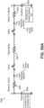
- 50A shows an electrical equivalent model 5000 of a pneumatic pressure control system of the types described herein in which the actual system includes one foot support bladder 200 ("cushion") and one fluid container 400 ("tank").
- the fluid container 400 and the foot support bladder 200 are modeled as capacitors and store pressure.
- Fluid flow through the various parts of the system is modeled as resistors (e.g., fluid flow between the fluid container 400 and the fluid transfer system 900 is shown as resistor 5020, fluid flow through the fluid transfer system 900 is shown as resistor 5022, and fluid flow between the foot support bladder 200 and the fluid transfer system 900 is shown as resistor 5024).
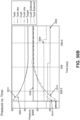
- Curve 5008 shows the actual pressure measurements taken by sensor 850A in the manifold/sealing connector fluid line in fluid communication with the fluid container 400
- curve 5010 shows the actual pressure measurements taken by sensor 850B in the manifold/sealing connector fluid line in fluid communication with the foot support bladder 200.
- the actual sensor 850A, 850B measurements jump significantly when flow starts and stops due to flow resistance offset. This flow resistance offset typically becomes even more pronounced as the fluid line cross sectional area decreases.
- pressure measurements may be taken: (a) at the pressure sensor(s) 850A, 850B located at manifold 800 and/or sealing connector 840 (P 850A , 850B ), and (b) at the additional pressure sensor(s) included with the foot support bladder 200 and/or fluid container 400 as part of the physical model (P ACTUAL ) under various operating conditions (e.g., using different flow rates, using different starting pressures, using different pressure change amounts, etc.).
- the differences in the actual measured pressures can be used to develop correction factors to be used in systems and methods where actual pressure measurements are available only at manifold 800 and/or sealing connector 840 (i.e., in actual shoes in use where no additional pressure sensor(s) is (are) included directly with the foot support bladder 200 and/or fluid container 400).
- the correction factor may take on the form of a look-up table, a mathematical formula or equation for converting P 850A , 850B to P ACTUAL , a "best fit" curve, etc., and may be applied by the microprocessor to the actual pressure readings P 850A , 850B .
Landscapes
- Engineering & Computer Science (AREA)
- General Engineering & Computer Science (AREA)
- Mechanical Engineering (AREA)
- Microelectronics & Electronic Packaging (AREA)
- Footwear And Its Accessory, Manufacturing Method And Apparatuses (AREA)
- Magnetically Actuated Valves (AREA)
- Push-Button Switches (AREA)
- Valve Housings (AREA)
- Textile Engineering (AREA)
- Multiple-Way Valves (AREA)
- Prostheses (AREA)
- Accommodation For Nursing Or Treatment Tables (AREA)
Applications Claiming Priority (15)
| Application Number | Priority Date | Filing Date | Title |
|---|---|---|---|
| US202063031423P | 2020-05-28 | 2020-05-28 | |
| US202063031413P | 2020-05-28 | 2020-05-28 | |
| US202063031441P | 2020-05-28 | 2020-05-28 | |
| US202063031395P | 2020-05-28 | 2020-05-28 | |
| US202063031444P | 2020-05-28 | 2020-05-28 | |
| US202063031471P | 2020-05-28 | 2020-05-28 | |
| US202063031455P | 2020-05-28 | 2020-05-28 | |
| US202063031433P | 2020-05-28 | 2020-05-28 | |
| US202063031468P | 2020-05-28 | 2020-05-28 | |
| US202063031451P | 2020-05-28 | 2020-05-28 | |
| US202063031429P | 2020-05-28 | 2020-05-28 | |
| US202063031482P | 2020-05-28 | 2020-05-28 | |
| US202063031460P | 2020-05-28 | 2020-05-28 | |
| EP21734651.9A EP4157010B1 (de) | 2020-05-28 | 2021-05-28 | Fussstützensysteme mit flüssigkeitsbewegungssteuergeräten und einstellbarem fussstützendruck |
| PCT/US2021/034737 WO2021243138A1 (en) | 2020-05-28 | 2021-05-28 | Foot support systems including fluid movement controllers and adjustable foot support pressure |
Related Parent Applications (1)
| Application Number | Title | Priority Date | Filing Date |
|---|---|---|---|
| EP21734651.9A Division EP4157010B1 (de) | 2020-05-28 | 2021-05-28 | Fussstützensysteme mit flüssigkeitsbewegungssteuergeräten und einstellbarem fussstützendruck |
Publications (3)
| Publication Number | Publication Date |
|---|---|
| EP4393340A2 true EP4393340A2 (de) | 2024-07-03 |
| EP4393340A3 EP4393340A3 (de) | 2024-10-02 |
| EP4393340B1 EP4393340B1 (de) | 2025-10-29 |
Family
ID=76523512
Family Applications (7)
| Application Number | Title | Priority Date | Filing Date |
|---|---|---|---|
| EP21734647.7A Active EP4157020B1 (de) | 2020-05-28 | 2021-05-28 | Fussstützensysteme mit flüssigkeitsbewegungssteuergeräten und einstellbarem fussstützendruck |
| EP21734662.6A Pending EP4157008A1 (de) | 2020-05-28 | 2021-05-28 | Fussstützensysteme mit flüssigkeitsbewegungssteuergeräten und einstellbarem fussstützendruck |
| EP21733676.7A Pending EP4157019A1 (de) | 2020-05-28 | 2021-05-28 | Fussstützensysteme mit flüssigkeitsbewegungssteuergeräten und einstellbarem fussstützendruck |
| EP24175150.2A Active EP4393340B1 (de) | 2020-05-28 | 2021-05-28 | Fussstützensysteme mit flüssigkeitsbewegungssteuergeräten und einstellbarem fussstützendruck |
| EP21734661.8A Pending EP4157011A1 (de) | 2020-05-28 | 2021-05-28 | Verfahren zur steuerung der flüssigkeitsbewegung in einem fussstützsystem |
| EP21734648.5A Active EP4157021B1 (de) | 2020-05-28 | 2021-05-28 | Fussstützensysteme mit flüssigkeitsbewegungssteuergeräten und einstellbarem fussstützendruck |
| EP21734651.9A Active EP4157010B1 (de) | 2020-05-28 | 2021-05-28 | Fussstützensysteme mit flüssigkeitsbewegungssteuergeräten und einstellbarem fussstützendruck |
Family Applications Before (3)
| Application Number | Title | Priority Date | Filing Date |
|---|---|---|---|
| EP21734647.7A Active EP4157020B1 (de) | 2020-05-28 | 2021-05-28 | Fussstützensysteme mit flüssigkeitsbewegungssteuergeräten und einstellbarem fussstützendruck |
| EP21734662.6A Pending EP4157008A1 (de) | 2020-05-28 | 2021-05-28 | Fussstützensysteme mit flüssigkeitsbewegungssteuergeräten und einstellbarem fussstützendruck |
| EP21733676.7A Pending EP4157019A1 (de) | 2020-05-28 | 2021-05-28 | Fussstützensysteme mit flüssigkeitsbewegungssteuergeräten und einstellbarem fussstützendruck |
Family Applications After (3)
| Application Number | Title | Priority Date | Filing Date |
|---|---|---|---|
| EP21734661.8A Pending EP4157011A1 (de) | 2020-05-28 | 2021-05-28 | Verfahren zur steuerung der flüssigkeitsbewegung in einem fussstützsystem |
| EP21734648.5A Active EP4157021B1 (de) | 2020-05-28 | 2021-05-28 | Fussstützensysteme mit flüssigkeitsbewegungssteuergeräten und einstellbarem fussstützendruck |
| EP21734651.9A Active EP4157010B1 (de) | 2020-05-28 | 2021-05-28 | Fussstützensysteme mit flüssigkeitsbewegungssteuergeräten und einstellbarem fussstützendruck |
Country Status (7)
| Country | Link |
|---|---|
| US (22) | US12011060B2 (de) |
| EP (7) | EP4157020B1 (de) |
| JP (10) | JP7508595B2 (de) |
| KR (7) | KR102814638B1 (de) |
| CN (6) | CN115776853A (de) |
| TW (6) | TW202532002A (de) |
| WO (13) | WO2021243181A1 (de) |
Families Citing this family (5)
| Publication number | Priority date | Publication date | Assignee | Title |
|---|---|---|---|---|
| CN111200951A (zh) * | 2017-08-21 | 2020-05-26 | 耐克创新有限合伙公司 | 包括流体填充囊腔的可调节的足部支撑系统 |
| USD958507S1 (en) * | 2021-04-29 | 2022-07-26 | Donghui Li | Sole |
| USD988660S1 (en) * | 2021-07-27 | 2023-06-13 | Frampton E. Ellis | Lateral side extension for the midfoot of a shoe sole |
| EP4561393A1 (de) * | 2022-07-28 | 2025-06-04 | NIKE Innovate C.V. | Schuhartikel mit blase an der fussseitigen oberfläche einer schaumstoffmittelsohlenschicht |
| USD1083331S1 (en) * | 2023-04-13 | 2025-07-15 | Nike, Inc. | Shoe |
Family Cites Families (189)
| Publication number | Priority date | Publication date | Assignee | Title |
|---|---|---|---|---|
| DE1287477B (de) | 1961-07-08 | 1969-01-16 | Opel Georg Von | Pneumatische Sohle fuer Schuhe |
| US3721265A (en) * | 1971-04-29 | 1973-03-20 | Fmc Corp | Three-way valve |
| US4358902A (en) * | 1980-04-02 | 1982-11-16 | Cole George S | Thrust producing shoe sole and heel |
| JPS5861931A (ja) * | 1981-10-08 | 1983-04-13 | Komatsu Ltd | トランスフアフイ−ダの素材搬送ストロ−ク切換装置 |
| GB2114425B (en) | 1982-02-05 | 1985-05-30 | Clarks Ltd | Sole units for footwear |
| US4446634A (en) | 1982-09-28 | 1984-05-08 | Johnson Paul H | Footwear having improved shock absorption |
| US4670995A (en) * | 1985-03-13 | 1987-06-09 | Huang Ing Chung | Air cushion shoe sole |
| US4674200A (en) * | 1985-12-12 | 1987-06-23 | Peter Sing | Slip resistant footwear |
| US5025575A (en) | 1989-03-14 | 1991-06-25 | Nikola Lakic | Inflatable sole lining for shoes and boots |
| US4991317A (en) * | 1987-05-26 | 1991-02-12 | Nikola Lakic | Inflatable sole lining for shoes and boots |
| US6014823A (en) * | 1987-05-26 | 2000-01-18 | Lakic; Nikola | Inflatable sole lining for shoes and boots |
| US5846063A (en) | 1987-05-26 | 1998-12-08 | Nikola Lakic | Miniature universal pump and valve for inflatable liners |
| US5199191A (en) | 1987-05-29 | 1993-04-06 | Armenak Moumdjian | Athletic shoe with inflatable mobile inner sole |
| US4936030A (en) * | 1987-06-23 | 1990-06-26 | Rennex Brian G | Energy efficient running shoe |
| US5295314A (en) * | 1987-07-17 | 1994-03-22 | Armenak Moumdjian | Shoe with sole including hollow space inflatable through removable bladder |
| WO1990009115A1 (en) | 1989-02-08 | 1990-08-23 | Reebok International Ltd. | An article of footwear |
| US4999932A (en) | 1989-02-14 | 1991-03-19 | Royce Medical Company | Variable support shoe |
| US5257470A (en) * | 1989-03-17 | 1993-11-02 | Nike, Inc. | Shoe bladder system |
| JPH07112441B2 (ja) | 1990-05-30 | 1995-12-06 | リーボック インターナショナル リミテッド | 膨張可能袋付き運動靴 |
| RU2060020C1 (ru) * | 1990-06-25 | 1996-05-20 | Юргенс Уте | Узел низа обуви |
| US5179792A (en) * | 1991-04-05 | 1993-01-19 | Brantingham Charles R | Shoe sole with randomly varying support pattern |
| US5222312A (en) | 1991-07-02 | 1993-06-29 | Doyle Harold S | Shoe with pneumatic inflating device |
| US5319866A (en) | 1991-08-21 | 1994-06-14 | Reebok International Ltd. | Composite arch member |
| US5406719A (en) | 1991-11-01 | 1995-04-18 | Nike, Inc. | Shoe having adjustable cushioning system |
| US5598645A (en) * | 1992-01-02 | 1997-02-04 | Adidas Ab | Shoe sole, in particular for sports shoes, with inflatable tube elements |
| EP0625013A4 (en) | 1992-01-31 | 1995-12-20 | Reebok Int Ltd | Support system for footwear. |
| DE4213054B4 (de) * | 1992-04-21 | 2005-09-15 | Robert Bosch Gmbh | Tastenanordnung |
| DE9205628U1 (de) * | 1992-04-25 | 1992-06-11 | Blaupunkt-Werke Gmbh, 31139 Hildesheim | Tastenanordnung zur Betätigung von Mikro-Tippschaltern |
| WO1993021790A1 (en) | 1992-04-30 | 1993-11-11 | L.A. Gear, Inc. | Shoe having an air bladder pressure indicator |
| US5335382A (en) * | 1992-11-23 | 1994-08-09 | Huang Yin Jun | Inflatable cushion device |
| JPH0723802A (ja) * | 1993-05-12 | 1995-01-27 | Fukuoka Kagaku Kogyo Kk | 換気靴 |
| US5384977A (en) | 1993-06-25 | 1995-01-31 | Global Sports Technologies Inc. | Sports footwear |
| US5375345A (en) * | 1993-09-29 | 1994-12-27 | Djuric; Zoran | Shoe with integral reversible air pump |
| US6453577B1 (en) * | 1996-02-09 | 2002-09-24 | Reebok International Ltd. | Support and cushioning system for an article of footwear |
| US5771606A (en) | 1994-10-14 | 1998-06-30 | Reebok International Ltd. | Support and cushioning system for an article of footwear |
| KR960016572B1 (ko) | 1994-03-10 | 1996-12-16 | 권중택 | 다기능 신발 |
| US5456027A (en) * | 1994-04-08 | 1995-10-10 | Vincent G. Tecchio | Athletic shoe with a detachable sole having an electronic breakaway system |
| US5860727A (en) * | 1994-04-12 | 1999-01-19 | Chien; Tseng-Lu | Shoe with an electro-luminescent lighting element |
| US6230501B1 (en) * | 1994-04-14 | 2001-05-15 | Promxd Technology, Inc. | Ergonomic systems and methods providing intelligent adaptive surfaces and temperature control |
| US5671552A (en) | 1995-07-18 | 1997-09-30 | Pettibone; Virginia G. | Atheletic shoe |
| JPH0956404A (ja) * | 1995-08-28 | 1997-03-04 | Masashi Noguchi | 履き物 |
| US5918383A (en) * | 1995-10-16 | 1999-07-06 | Fila U.S.A., Inc. | Sports shoe having an elastic insert |
| US5673500A (en) * | 1995-12-11 | 1997-10-07 | Raymond Hwang | Shoe with weighing means |
| US5813142A (en) | 1996-02-09 | 1998-09-29 | Demon; Ronald S. | Shoe sole with an adjustable support pattern |
| US5816290A (en) * | 1996-03-13 | 1998-10-06 | Fleck Controls, Inc. | Rotary control valve for a water conditioning system |
| US5820133A (en) * | 1996-03-15 | 1998-10-13 | Fleck Controls, Inc. | Rotary control valve and seal mechanism |
| TW394675B (en) | 1996-06-17 | 2000-06-21 | Huang Ying Jiun | Automatic inflatable air cushion |
| US6725573B2 (en) * | 1997-06-03 | 2004-04-27 | Harold S. Doyle | Pneumatic inflating device contained entirely within shoe sole |
| US6305102B1 (en) * | 1997-06-03 | 2001-10-23 | Harold S. Doyle | Pneumatic inflating device |
| BR9714773A (pt) * | 1997-06-16 | 2000-07-25 | Chung Ing Huang | Almofada de ar auto-inflável |
| US7107706B1 (en) * | 1997-08-14 | 2006-09-19 | Promdx Technology, Inc. | Ergonomic systems and methods providing intelligent adaptive surfaces and temperature control |
| US6432102B2 (en) | 1999-03-15 | 2002-08-13 | Cryovascular Systems, Inc. | Cryosurgical fluid supply |
| US7219449B1 (en) * | 1999-05-03 | 2007-05-22 | Promdx Technology, Inc. | Adaptively controlled footwear |
| US6290662B1 (en) * | 1999-05-28 | 2001-09-18 | John K. Morris | Portable, self-contained apparatus for deep vein thrombosis (DVT) prophylaxis |
| US6354020B1 (en) | 1999-09-16 | 2002-03-12 | Reebok International Ltd. | Support and cushioning system for an article of footwear |
| US6463679B1 (en) * | 1999-10-21 | 2002-10-15 | Yamamoto Limited | Forced ventilation system inside soles |
| KR20010045104A (ko) | 1999-11-02 | 2001-06-05 | 안갑엽 | 자동조각기의 가공물 고정장치 |
| US6402879B1 (en) | 2000-03-16 | 2002-06-11 | Nike, Inc. | Method of making bladder with inverted edge seam |
| US6571490B2 (en) | 2000-03-16 | 2003-06-03 | Nike, Inc. | Bladder with multi-stage regionalized cushioning |
| US6430843B1 (en) | 2000-04-18 | 2002-08-13 | Nike, Inc. | Dynamically-controlled cushioning system for an article of footwear |
| US20020194747A1 (en) * | 2001-06-21 | 2002-12-26 | Passke Joel L. | Footwear with bladder filter |
| KR100404102B1 (ko) * | 2001-09-04 | 2003-11-03 | 엘지전자 주식회사 | 휴대단말기의 키패드 백라이팅 장치 |
| GB2391110B (en) * | 2002-06-20 | 2005-07-13 | In2Tec Ltd | Switches |
| US7278445B2 (en) * | 2002-07-02 | 2007-10-09 | Reebok International Ltd. | Shoe having an inflatable bladder |
| US6785985B2 (en) * | 2002-07-02 | 2004-09-07 | Reebok International Ltd. | Shoe having an inflatable bladder |
| US6946050B2 (en) * | 2003-01-27 | 2005-09-20 | Nike, Llc | Method for flange bonding |
| US7631382B2 (en) * | 2003-03-10 | 2009-12-15 | Adidas International Marketing B.V. | Intelligent footwear systems |
| US6889451B2 (en) * | 2003-04-23 | 2005-05-10 | Mike, Inc. | Fluid system with internal filter |
| KR100534033B1 (ko) | 2003-07-12 | 2005-12-08 | 주식회사 피스포스 | 신발의 펌핑구조 |
| US7448150B1 (en) | 2004-02-26 | 2008-11-11 | Reebok International Ltd. | Insert with variable cushioning and support and article of footwear containing same |
| US7093818B2 (en) * | 2004-08-03 | 2006-08-22 | Harris Corporation | Embedded control valve using homopolar motor |
| US7013585B2 (en) * | 2004-08-12 | 2006-03-21 | Chie-Fang Lo | Cushion device for shoes |
| WO2006073214A1 (en) | 2005-01-06 | 2006-07-13 | Jong Soo Cho | Footwear with ventilating and shock-absorbing device |
| US7331121B2 (en) * | 2005-01-19 | 2008-02-19 | Chie-Fang Lo | Inflatable shoe sole |
| US20080167580A1 (en) * | 2005-04-05 | 2008-07-10 | Andante Medical Devices Ltd. | Rehabilitation System |
| KR20060114964A (ko) | 2005-05-03 | 2006-11-08 | 삼성전자주식회사 | 냉장고 및 그 제어 방법 |
| US20070006489A1 (en) | 2005-07-11 | 2007-01-11 | Nike, Inc. | Control systems and foot-receiving device products containing such systems |
| US7546696B1 (en) * | 2005-10-17 | 2009-06-16 | Reebok International Ltd. | Inflation mechanism and outlet valve for an article of footwear incorporating an inflatable bladder |
| US7451554B2 (en) | 2005-10-19 | 2008-11-18 | Nike, Inc. | Fluid system having an expandable pump chamber |
| US7478488B1 (en) * | 2005-10-31 | 2009-01-20 | Reebok International Ltd. | Inflatable and ventilating upper for an article of footwear |
| US7404263B2 (en) * | 2006-01-11 | 2008-07-29 | Bbc International, Llc | Footwear with force sensing device |
| FR2898017B1 (fr) * | 2006-03-03 | 2008-05-09 | Philippe Biesse | Semelle universelle. |
| CN201071958Y (zh) * | 2006-10-27 | 2008-06-11 | 傲胜国际股份有限公司 | 阀体、阀机构、流体泵装置及按摩鞋系统 |
| WO2008051164A1 (en) | 2006-10-27 | 2008-05-02 | Osim International Ltd | A valve body and massaging system using the same |
| US20100094184A1 (en) * | 2006-10-27 | 2010-04-15 | Wai Mun James Wong | Air bag and an apparatus and system having the same |
| US7694438B1 (en) * | 2006-12-13 | 2010-04-13 | Reebok International Ltd. | Article of footwear having an adjustable ride |
| US7578077B2 (en) * | 2006-12-18 | 2009-08-25 | Michel Marc | Shoe sole construction |
| US7934521B1 (en) * | 2006-12-20 | 2011-05-03 | Reebok International, Ltd. | Configurable fluid transfer manifold for inflatable footwear |
| US8230874B2 (en) * | 2006-12-20 | 2012-07-31 | Reebok International Limited | Configurable fluid transfer manifold for inflatable footwear |
| US8015730B2 (en) * | 2007-01-08 | 2011-09-13 | Nike, Inc. | Footwear with vertically-arranged pump and pressure chambers |
| US8414275B1 (en) | 2007-01-11 | 2013-04-09 | Reebok International Limited | Pump and valve combination for an article of footwear incorporating an inflatable bladder |
| US20080222769A1 (en) * | 2007-03-15 | 2008-09-18 | Hillary Natonson | Garment-integrated proprioceptive feedback system |
| KR100777252B1 (ko) * | 2007-03-16 | 2007-11-28 | 광 지 진 | 공기 유입 밸브가 결합되고 외부로 표시되는 에어 튜브를형성한 신발의 바닥창 |
| JP2009014971A (ja) * | 2007-07-04 | 2009-01-22 | Nec Electronics Corp | 表示ドライバ回路 |
| US7552717B2 (en) | 2007-08-07 | 2009-06-30 | Delphi Technologies, Inc. | Fuel injector and method for controlling fuel injectors |
| WO2009027941A2 (en) * | 2007-08-28 | 2009-03-05 | Prontopharma-Europe S.R.L. | A sole including a system of blisters and devices for their deflation |
| GB0720706D0 (en) | 2007-10-23 | 2007-12-05 | Shadowfax Medical Ltd | Improvements in or relating to footwear |
| JP5118214B2 (ja) * | 2008-03-13 | 2013-01-16 | ケーシーアイ ライセンシング インコーポレイテッド | 荷重軽減減圧治療システムおよび方法 |
| TW200946152A (en) * | 2008-03-13 | 2009-11-16 | Kci Licensing Inc | System and method for reduced pressure charging |
| US9549585B2 (en) * | 2008-06-13 | 2017-01-24 | Nike, Inc. | Footwear having sensor system |
| US8250782B2 (en) * | 2009-03-26 | 2012-08-28 | Reebok International Limited | Valve for regulating pressure in a fluid system |
| US8307569B2 (en) | 2009-04-01 | 2012-11-13 | Reebok International Limited | Training footwear |
| SE537288C2 (sv) * | 2009-05-18 | 2015-03-24 | Nordhydraulic Ab | Strömbrytaranordning och förfarande för tillverkning av sådan |
| KR101592306B1 (ko) * | 2009-07-31 | 2016-02-05 | 엘지전자 주식회사 | 액체분사모듈이 구비된 의류건조기의 운전방법 |
| US20110047817A1 (en) | 2009-08-25 | 2011-03-03 | Francello Gene A | Sole construction for shoe having self-pumping extendable spikes |
| JP5388150B2 (ja) | 2009-08-26 | 2014-01-15 | エルジー・ケム・リミテッド | 導電性金属インク組成物および導電性パターンの形成方法 |
| US8800167B2 (en) | 2009-09-19 | 2014-08-12 | Harold S. Doyle | Pneumatic inflating device contained entirely within shoe sole |
| US9521877B2 (en) * | 2013-02-21 | 2016-12-20 | Nike, Inc. | Article of footwear with outsole bonded to cushioning component and method of manufacturing an article of footwear |
| US20110131839A1 (en) | 2009-12-03 | 2011-06-09 | C-Boot Ltd. | Pneumatic Alternating Pressure Relief of a Foot |
| KR101008305B1 (ko) | 2010-07-05 | 2011-01-14 | 김성순 | 에어백을 갖는 신발 안창 |
| JP2012016447A (ja) * | 2010-07-07 | 2012-01-26 | Toyota Motor Corp | 足底機構 |
| US20150305436A1 (en) * | 2010-09-24 | 2015-10-29 | Harold S. Doyle | Pneumatically inflatable air bladder devices contained entirely within shoe sole or configured as shoe inserts |
| US20120073161A1 (en) * | 2010-09-24 | 2012-03-29 | Doyle Harold S | Pneumatically inflatable air bladder devices contained entirely within shoe sole or configured as shoe inserts |
| JP2011087946A (ja) | 2010-11-13 | 2011-05-06 | Takeshi Sawakoshi | 歩行推進力発生装置 |
| GB201102637D0 (en) * | 2011-02-15 | 2011-03-30 | Shadowfax Medical Ltd | Improvements in or relating to footwear |
| PE20141322A1 (es) | 2011-03-25 | 2014-10-05 | Glaxosmithkline Intellectual Property (N 2) Limited | Ciclopropilaminas como inhibidores de desmetilasa 1 especifica de lisina |
| US8844165B2 (en) | 2011-04-06 | 2014-09-30 | Nike, Inc. | Adjustable bladder system with external valve for an article of footwear |
| US8857076B2 (en) * | 2011-04-06 | 2014-10-14 | Nike, Inc. | Article of footwear with an adaptive fluid system |
| US9060564B2 (en) * | 2011-04-06 | 2015-06-23 | Nike, Inc. | Adjustable multi-bladder system for an article of footwear |
| US8813389B2 (en) * | 2011-04-06 | 2014-08-26 | Nike, Inc. | Adjustable bladder system for an article of footwear |
| US9770624B2 (en) * | 2011-10-14 | 2017-09-26 | Chris Norcross Bender | Sport-boot pressure monitor and method of use |
| US8935860B2 (en) * | 2011-10-28 | 2015-01-20 | George Torres | Self-tightening shoe |
| US9609913B2 (en) | 2011-12-29 | 2017-04-04 | Reebok International Limited | Sole and article of footwear having a pod assemby |
| US11071344B2 (en) * | 2012-02-22 | 2021-07-27 | Nike, Inc. | Motorized shoe with gesture control |
| US20130213147A1 (en) * | 2012-02-22 | 2013-08-22 | Nike, Inc. | Footwear Having Sensor System |
| US20130213144A1 (en) * | 2012-02-22 | 2013-08-22 | Nike, Inc. | Footwear Having Sensor System |
| US8914994B2 (en) | 2012-03-02 | 2014-12-23 | Nike, Inc. | Guitar-shaped bladder for footwear |
| US20130278436A1 (en) | 2012-04-18 | 2013-10-24 | Frampton E. Ellis | Smartphone-controlled active configuration of footwear including with concavely rounded soles |
| US9030335B2 (en) * | 2012-04-18 | 2015-05-12 | Frampton E. Ellis | Smartphones app-controlled configuration of footwear soles using sensors in the smartphone and the soles |
| US9420847B2 (en) | 2012-04-25 | 2016-08-23 | Nike, Inc. | Article of footwear with bladder and method of manufacturing the same |
| US9510646B2 (en) * | 2012-07-17 | 2016-12-06 | Nike, Inc. | Article of footwear having a flexible fluid-filled chamber |
| EP2887912B1 (de) * | 2012-08-23 | 2021-10-06 | Djo, Llc | Stütze mit einer aufblassteuerung |
| CN103660816A (zh) | 2012-09-11 | 2014-03-26 | 伊顿公司 | 自关闭式过滤器 |
| US9259047B2 (en) | 2012-09-13 | 2016-02-16 | Thomas Nikita Krupenkin | Apparatus for footwear-embedded mechanical energy harvesting system based on dual-loop channel |
| US10849387B2 (en) * | 2012-09-20 | 2020-12-01 | Nike, Inc. | Sole structures and articles of footwear having plate moderated fluid-filled bladders and/or foam type impact force attenuation members |
| US9066558B2 (en) | 2012-12-17 | 2015-06-30 | Nike, Inc. | Electronically controlled bladder assembly |
| US11006690B2 (en) | 2013-02-01 | 2021-05-18 | Nike, Inc. | System and method for analyzing athletic activity |
| US9603414B2 (en) | 2013-03-15 | 2017-03-28 | Nike, Inc. | Fluid-filled chamber with a tensile element |
| US10024740B2 (en) * | 2013-03-15 | 2018-07-17 | Nike, Inc. | System and method for analyzing athletic activity |
| WO2014186112A1 (en) * | 2013-05-17 | 2014-11-20 | Ninepoint Medical, Inc. | Inflation apparatus with pressure relief, related systems, methods and kits |
| WO2015002827A1 (en) * | 2013-07-01 | 2015-01-08 | BUDDIES, Step | System, apparatus, and method for measuring number of user steps |
| JP2015051065A (ja) * | 2013-09-05 | 2015-03-19 | 株式会社安川電機 | 歩行支援情報提示装置 |
| EP3046434B1 (de) * | 2013-09-20 | 2019-05-22 | NIKE Innovate C.V. | Schuhwerk mit abnehmbarem motorisiertem einstellsystem |
| US10433613B2 (en) * | 2014-01-13 | 2019-10-08 | Alexander Litvinov | Ventilation apparatus for footwear |
| EP3174080B1 (de) * | 2014-07-26 | 2018-11-28 | Power Idea Technology (Shenzhen) Co., Ltd. | Wasserdichte struktur für knopf an einem elektronischen produkt und wasserdichtes mobiltelefon damit |
| CN104791522B (zh) * | 2015-04-15 | 2017-05-10 | 华中科技大学 | 一种油路切换装置 |
| EP3135966A1 (de) | 2015-08-31 | 2017-03-01 | bNovate Technologies SA | Drehventil |
| US11103030B2 (en) | 2015-10-07 | 2021-08-31 | Puma SE | Article of footwear having an automatic lacing system |
| US11185130B2 (en) * | 2015-10-07 | 2021-11-30 | Puma SE | Article of footwear having an automatic lacing system |
| US10932523B2 (en) | 2015-11-30 | 2021-03-02 | Nike, Inc. | Electrorheological fluid structure with attached conductor and method of fabrication |
| US10709206B2 (en) * | 2015-11-30 | 2020-07-14 | Nike, Inc. | Method of filling electrorheological fluid structure |
| DE102015225209A1 (de) * | 2015-12-15 | 2017-06-22 | VPAM Holding GmbH | Vorrichtung mit einem veränderlichen Kammersystem |
| CN105394872B (zh) * | 2015-12-17 | 2017-02-22 | 湖南师范大学 | 运动鞋 |
| US10102722B2 (en) * | 2015-12-18 | 2018-10-16 | Immersion Corporation | Wearable article having an actuator that performs non-haptic and haptic operations |
| CA3016423A1 (en) * | 2016-03-09 | 2017-09-14 | Tactile Systems Technology, Inc. | Mitt for compression garments |
| US10390589B2 (en) | 2016-03-15 | 2019-08-27 | Nike, Inc. | Drive mechanism for automated footwear platform |
| US11202484B2 (en) * | 2016-03-15 | 2021-12-21 | Nike, Inc. | Standoff unit for a control device in an article of footwear |
| US20170296096A1 (en) * | 2016-04-13 | 2017-10-19 | Hepta 7291 LLC | Wearable device and method for detecting reflective zones using sensors |
| WO2017190049A1 (en) | 2016-04-29 | 2017-11-02 | Lifelens Technologies, Llc | Monitoring and management of physiologic parameters of a subject |
| TWM530059U (zh) * | 2016-05-10 | 2016-10-11 | Homeway Technology Co Ltd | 穿戴式計步鞋 |
| US20180008005A1 (en) * | 2016-07-06 | 2018-01-11 | Patricia Vandervoort | Footwear with deployable and retractable tractive features |
| WO2018098463A1 (en) | 2016-11-28 | 2018-05-31 | The Board Of Regents Of The University Of Texas System | Dual-layer insole apparatuses for diabetic foot lesion prevention and related methods |
| TWI665973B (zh) * | 2016-12-16 | 2019-07-21 | 欣合信股份有限公司 | Sole air cushion device |
| TWI675641B (zh) * | 2017-02-01 | 2019-11-01 | 世擘股份有限公司 | 電子裝置 |
| WO2018157039A1 (en) * | 2017-02-27 | 2018-08-30 | Nike Innovate C.V. | Adjustable foot support systems including fluid-filled bladder chambers |
| US10258102B2 (en) * | 2017-03-07 | 2019-04-16 | Welter's Co., Ltd. | Airbag device with pressure regulating function |
| KR102805177B1 (ko) * | 2017-03-14 | 2025-05-08 | 나이키 이노베이트 씨.브이. | 신발류 물품 및 조임 디바이스의 설치 방법 |
| JP6908436B2 (ja) | 2017-05-30 | 2021-07-28 | 京セラ株式会社 | 履物およびシステム |
| JP2018201609A (ja) | 2017-05-30 | 2018-12-27 | 京セラ株式会社 | 履物およびシステム |
| US11285778B2 (en) * | 2017-06-14 | 2022-03-29 | Denso Corporation | Valve device |
| US10883619B2 (en) | 2017-06-27 | 2021-01-05 | Hayward Industries, Inc. | Multi-position valve |
| TWI678978B (zh) * | 2017-07-03 | 2019-12-11 | 研能科技股份有限公司 | 動態控壓氣墊裝置 |
| CN111200951A (zh) * | 2017-08-21 | 2020-05-26 | 耐克创新有限合伙公司 | 包括流体填充囊腔的可调节的足部支撑系统 |
| FR3071898B1 (fr) * | 2017-10-04 | 2020-07-10 | Valeo Systemes De Controle Moteur | Actionneur et vanne de circulation de fluide le comprenant |
| KR20190053572A (ko) | 2017-11-10 | 2019-05-20 | 주식회사 씨앤씨네이처 | 알긴산을 유효성분으로 함유하는 운동능력 및 지구력 향상용 조성물 |
| TWM562025U (zh) | 2017-11-24 | 2018-06-21 | 沅聖科技股份有限公司 | 智慧鞋墊模組 |
| CN207855136U (zh) * | 2017-12-20 | 2018-09-14 | 王国义 | 一种气垫鞋底 |
| US10524539B2 (en) * | 2018-01-02 | 2020-01-07 | Chih-Fang Lo | Inflatable air pad of shoe |
| TWM562028U (zh) | 2018-03-19 | 2018-06-21 | 沅聖科技股份有限公司 | 智慧鞋模組 |
| FR3079734B1 (fr) * | 2018-04-06 | 2024-12-20 | Zhor Tech | Systeme pour la detection d'un trouble de la demarche chez un utilisateur et procedes associes. |
| US20190366668A1 (en) * | 2018-05-30 | 2019-12-05 | Nike, Inc. | Manufacturing system for a cushioning footwear |
| WO2019231970A1 (en) | 2018-05-31 | 2019-12-05 | Nike Innovate C.V. | Fluid flow control devices usable in adjustable foot support systems |
| WO2019231968A1 (en) * | 2018-05-31 | 2019-12-05 | Nike Innovate C.V. | Adjustable foot support systems including fluid-filled bladder chambers |
| WO2020113014A1 (en) | 2018-11-29 | 2020-06-04 | Nike Innovate C.V. | Foot support systems including fluid filled bladders with movement of fluid between bladders |
| US11523657B2 (en) * | 2019-05-20 | 2022-12-13 | Nike, Inc. | Foot support systems including fluid movement controllers |
| CN110090362A (zh) * | 2019-06-04 | 2019-08-06 | 天津滨海华医光电技术有限公司 | 一种弱激光糖尿病足理疗鞋垫 |
| JP6968128B2 (ja) | 2019-07-18 | 2021-11-17 | 株式会社日本トリム | 弁装置及び電解水生成装置 |
| US11653712B2 (en) * | 2020-02-10 | 2023-05-23 | Reebok International Limited | Automatic inflation pump bladder system |
| KR20240090918A (ko) * | 2021-11-24 | 2024-06-21 | 나이키 이노베이트 씨.브이. | 유체 이동 제어기 및 조정 가능한 발 지지 압력을 포함하는 발 지지 시스템 |
-
2021
- 2021-05-28 EP EP21734647.7A patent/EP4157020B1/de active Active
- 2021-05-28 TW TW114114580A patent/TW202532002A/zh unknown
- 2021-05-28 CN CN202180049575.0A patent/CN115776853A/zh active Pending
- 2021-05-28 WO PCT/US2021/034803 patent/WO2021243181A1/en not_active Ceased
- 2021-05-28 JP JP2022572682A patent/JP7508595B2/ja active Active
- 2021-05-28 US US17/333,630 patent/US12011060B2/en active Active
- 2021-05-28 CN CN202180048823.XA patent/CN115867162A/zh active Pending
- 2021-05-28 TW TW114114801A patent/TW202532003A/zh unknown
- 2021-05-28 US US17/333,785 patent/US12035779B2/en active Active
- 2021-05-28 CN CN202180048347.1A patent/CN115915992A/zh active Pending
- 2021-05-28 WO PCT/US2021/034749 patent/WO2021243146A1/en not_active Ceased
- 2021-05-28 US US17/334,015 patent/US11957207B2/en active Active
- 2021-05-28 CN CN202180048564.0A patent/CN115867165A/zh active Pending
- 2021-05-28 WO PCT/US2021/034812 patent/WO2021243187A1/en not_active Ceased
- 2021-05-28 EP EP21734662.6A patent/EP4157008A1/de active Pending
- 2021-05-28 US US17/334,049 patent/US11969052B2/en active Active
- 2021-05-28 TW TW110119574A patent/TWI831014B/zh active
- 2021-05-28 JP JP2022572681A patent/JP7512435B2/ja active Active
- 2021-05-28 EP EP21733676.7A patent/EP4157019A1/de active Pending
- 2021-05-28 US US17/333,493 patent/US11825905B2/en active Active
- 2021-05-28 WO PCT/US2021/034737 patent/WO2021243138A1/en not_active Ceased
- 2021-05-28 KR KR1020227045879A patent/KR102814638B1/ko active Active
- 2021-05-28 KR KR1020257016887A patent/KR20250078618A/ko active Pending
- 2021-05-28 KR KR1020227045866A patent/KR102823467B1/ko active Active
- 2021-05-28 US US17/333,333 patent/US11864618B2/en active Active
- 2021-05-28 EP EP24175150.2A patent/EP4393340B1/de active Active
- 2021-05-28 KR KR1020227045856A patent/KR102813947B1/ko active Active
- 2021-05-28 WO PCT/US2021/034716 patent/WO2021243124A1/en not_active Ceased
- 2021-05-28 TW TW112108180A patent/TWI847579B/zh active
- 2021-05-28 US US17/333,867 patent/US12075882B2/en active Active
- 2021-05-28 KR KR1020227045857A patent/KR102814636B1/ko active Active
- 2021-05-28 WO PCT/US2021/034726 patent/WO2021243130A1/en not_active Ceased
- 2021-05-28 JP JP2022572700A patent/JP7512438B2/ja active Active
- 2021-05-28 WO PCT/US2021/034733 patent/WO2021243135A1/en not_active Ceased
- 2021-05-28 KR KR1020227045865A patent/KR102814634B1/ko active Active
- 2021-05-28 TW TW114114579A patent/TW202532001A/zh unknown
- 2021-05-28 EP EP21734661.8A patent/EP4157011A1/de active Pending
- 2021-05-28 WO PCT/US2021/034755 patent/WO2021243150A1/en not_active Ceased
- 2021-05-28 US US17/333,974 patent/US12538960B2/en active Active
- 2021-05-28 EP EP21734648.5A patent/EP4157021B1/de active Active
- 2021-05-28 US US17/333,735 patent/US12075881B2/en active Active
- 2021-05-28 JP JP2022572699A patent/JP7512437B2/ja active Active
- 2021-05-28 WO PCT/US2021/034741 patent/WO2021243140A1/en not_active Ceased
- 2021-05-28 CN CN202180049637.8A patent/CN115835795A/zh active Pending
- 2021-05-28 WO PCT/US2021/034892 patent/WO2021243232A1/en not_active Ceased
- 2021-05-28 CN CN202180048816.XA patent/CN115835797A/zh active Pending
- 2021-05-28 TW TW113120758A patent/TWI883986B/zh active
- 2021-05-28 WO PCT/US2021/034720 patent/WO2021243128A1/en not_active Ceased
- 2021-05-28 EP EP21734651.9A patent/EP4157010B1/de active Active
- 2021-05-28 WO PCT/US2021/034775 patent/WO2021243164A1/en not_active Ceased
- 2021-05-28 WO PCT/US2021/034886 patent/WO2021243228A1/en not_active Ceased
- 2021-05-28 JP JP2022572685A patent/JP7588160B2/ja active Active
- 2021-05-28 KR KR1020227045892A patent/KR102823468B1/ko active Active
- 2021-05-28 JP JP2022572696A patent/JP7512436B2/ja active Active
- 2021-05-28 US US17/333,555 patent/US12089692B2/en active Active
- 2021-05-28 US US17/333,683 patent/US12096819B2/en active Active
- 2021-05-28 US US17/333,919 patent/US12193540B2/en active Active
- 2021-05-28 US US17/333,309 patent/US11832686B2/en active Active
-
2023
- 2023-10-23 US US18/492,089 patent/US12220020B2/en active Active
- 2023-10-25 US US18/493,980 patent/US20240065377A1/en active Pending
- 2023-11-28 US US18/521,239 patent/US12290137B2/en active Active
-
2024
- 2024-03-27 US US18/618,494 patent/US20240251910A1/en active Pending
- 2024-05-03 US US18/654,768 patent/US20240285029A1/en active Pending
- 2024-05-30 US US18/678,305 patent/US20240315393A1/en active Pending
- 2024-06-19 JP JP2024098854A patent/JP7747824B2/ja active Active
- 2024-06-26 JP JP2024102739A patent/JP2024138303A/ja active Pending
- 2024-06-26 JP JP2024102727A patent/JP7692092B2/ja active Active
- 2024-06-26 JP JP2024102761A patent/JP2024147579A/ja active Pending
- 2024-07-08 US US18/766,048 patent/US20240358117A1/en active Pending
- 2024-07-22 US US18/779,364 patent/US20240373981A1/en active Pending
- 2024-12-09 US US18/973,922 patent/US20250098814A1/en active Pending
Also Published As
Similar Documents
| Publication | Publication Date | Title |
|---|---|---|
| EP4393340B1 (de) | Fussstützensysteme mit flüssigkeitsbewegungssteuergeräten und einstellbarem fussstützendruck | |
| WO2023097139A1 (en) | Foot support systems including fluid movement controllers and adjustable foot support pressure | |
| JP7812884B2 (ja) | 流体移動制御および調整可能足支持圧力を含む足支持システム |
Legal Events
| Date | Code | Title | Description |
|---|---|---|---|
| PUAI | Public reference made under article 153(3) epc to a published international application that has entered the european phase |
Free format text: ORIGINAL CODE: 0009012 |
|
| STAA | Information on the status of an ep patent application or granted ep patent |
Free format text: STATUS: THE APPLICATION HAS BEEN PUBLISHED |
|
| AC | Divisional application: reference to earlier application |
Ref document number: 4157010 Country of ref document: EP Kind code of ref document: P |
|
| AK | Designated contracting states |
Kind code of ref document: A2 Designated state(s): AL AT BE BG CH CY CZ DE DK EE ES FI FR GB GR HR HU IE IS IT LI LT LU LV MC MK MT NL NO PL PT RO RS SE SI SK SM TR |
|
| REG | Reference to a national code |
Ref country code: DE Ref legal event code: R079 Free format text: PREVIOUS MAIN CLASS: A43B0013200000 Ipc: A43B0003340000 Ref country code: DE Ref legal event code: R079 Ref document number: 602021041617 Country of ref document: DE Free format text: PREVIOUS MAIN CLASS: A43B0013200000 Ipc: A43B0003340000 |
|
| PUAL | Search report despatched |
Free format text: ORIGINAL CODE: 0009013 |
|
| AK | Designated contracting states |
Kind code of ref document: A3 Designated state(s): AL AT BE BG CH CY CZ DE DK EE ES FI FR GB GR HR HU IE IS IT LI LT LU LV MC MK MT NL NO PL PT RO RS SE SI SK SM TR |
|
| RIC1 | Information provided on ipc code assigned before grant |
Ipc: F16K 27/06 20060101ALI20240828BHEP Ipc: F16K 11/085 20060101ALI20240828BHEP Ipc: A43B 13/18 20060101ALI20240828BHEP Ipc: A43B 13/20 20060101ALI20240828BHEP Ipc: A43B 3/34 20220101AFI20240828BHEP |
|
| STAA | Information on the status of an ep patent application or granted ep patent |
Free format text: STATUS: REQUEST FOR EXAMINATION WAS MADE |
|
| 17P | Request for examination filed |
Effective date: 20250306 |
|
| GRAP | Despatch of communication of intention to grant a patent |
Free format text: ORIGINAL CODE: EPIDOSNIGR1 |
|
| STAA | Information on the status of an ep patent application or granted ep patent |
Free format text: STATUS: GRANT OF PATENT IS INTENDED |
|
| INTG | Intention to grant announced |
Effective date: 20250522 |
|
| RAP3 | Party data changed (applicant data changed or rights of an application transferred) |
Owner name: NIKE INNOVATE C.V. |
|
| P01 | Opt-out of the competence of the unified patent court (upc) registered |
Free format text: CASE NUMBER: APP_24993/2025 Effective date: 20250526 |
|
| GRAS | Grant fee paid |
Free format text: ORIGINAL CODE: EPIDOSNIGR3 |
|
| GRAA | (expected) grant |
Free format text: ORIGINAL CODE: 0009210 |
|
| STAA | Information on the status of an ep patent application or granted ep patent |
Free format text: STATUS: THE PATENT HAS BEEN GRANTED |
|
| AC | Divisional application: reference to earlier application |
Ref document number: 4157010 Country of ref document: EP Kind code of ref document: P |
|
| AK | Designated contracting states |
Kind code of ref document: B1 Designated state(s): AL AT BE BG CH CY CZ DE DK EE ES FI FR GB GR HR HU IE IS IT LI LT LU LV MC MK MT NL NO PL PT RO RS SE SI SK SM TR |
|
| REG | Reference to a national code |
Ref country code: CH Ref legal event code: F10 Free format text: ST27 STATUS EVENT CODE: U-0-0-F10-F00 (AS PROVIDED BY THE NATIONAL OFFICE) Effective date: 20251029 Ref country code: GB Ref legal event code: FG4D |
|
| REG | Reference to a national code |
Ref country code: IE Ref legal event code: FG4D |
|
| REG | Reference to a national code |
Ref country code: DE Ref legal event code: R096 Ref document number: 602021041617 Country of ref document: DE |