EP4384048B1 - Möbel mit einer vorrichtung zum halten, abbremsen oder beschleunigen eines bewegbaren möbelteils - Google Patents
Möbel mit einer vorrichtung zum halten, abbremsen oder beschleunigen eines bewegbaren möbelteils Download PDFInfo
- Publication number
- EP4384048B1 EP4384048B1 EP22762058.0A EP22762058A EP4384048B1 EP 4384048 B1 EP4384048 B1 EP 4384048B1 EP 22762058 A EP22762058 A EP 22762058A EP 4384048 B1 EP4384048 B1 EP 4384048B1
- Authority
- EP
- European Patent Office
- Prior art keywords
- activator
- driver
- spring element
- furniture
- piece
- Prior art date
- Legal status (The legal status is an assumption and is not a legal conclusion. Google has not performed a legal analysis and makes no representation as to the accuracy of the status listed.)
- Active
Links
Images



Classifications
-
- A—HUMAN NECESSITIES
- A47—FURNITURE; DOMESTIC ARTICLES OR APPLIANCES; COFFEE MILLS; SPICE MILLS; SUCTION CLEANERS IN GENERAL
- A47B—TABLES; DESKS; OFFICE FURNITURE; CABINETS; DRAWERS; GENERAL DETAILS OF FURNITURE
- A47B88/00—Drawers for tables, cabinets or like furniture; Guides for drawers
- A47B88/40—Sliding drawers; Slides or guides therefor
- A47B88/453—Actuated drawers
- A47B88/46—Actuated drawers operated by mechanically-stored energy, e.g. by springs
- A47B88/463—Actuated drawers operated by mechanically-stored energy, e.g. by springs self-opening
-
- A—HUMAN NECESSITIES
- A47—FURNITURE; DOMESTIC ARTICLES OR APPLIANCES; COFFEE MILLS; SPICE MILLS; SUCTION CLEANERS IN GENERAL
- A47B—TABLES; DESKS; OFFICE FURNITURE; CABINETS; DRAWERS; GENERAL DETAILS OF FURNITURE
- A47B88/00—Drawers for tables, cabinets or like furniture; Guides for drawers
- A47B88/40—Sliding drawers; Slides or guides therefor
- A47B88/473—Braking devices, e.g. linear or rotational dampers or friction brakes; Buffers; End stops
-
- A—HUMAN NECESSITIES
- A47—FURNITURE; DOMESTIC ARTICLES OR APPLIANCES; COFFEE MILLS; SPICE MILLS; SUCTION CLEANERS IN GENERAL
- A47B—TABLES; DESKS; OFFICE FURNITURE; CABINETS; DRAWERS; GENERAL DETAILS OF FURNITURE
- A47B88/00—Drawers for tables, cabinets or like furniture; Guides for drawers
- A47B88/40—Sliding drawers; Slides or guides therefor
- A47B88/453—Actuated drawers
- A47B88/46—Actuated drawers operated by mechanically-stored energy, e.g. by springs
-
- A—HUMAN NECESSITIES
- A47—FURNITURE; DOMESTIC ARTICLES OR APPLIANCES; COFFEE MILLS; SPICE MILLS; SUCTION CLEANERS IN GENERAL
- A47B—TABLES; DESKS; OFFICE FURNITURE; CABINETS; DRAWERS; GENERAL DETAILS OF FURNITURE
- A47B88/00—Drawers for tables, cabinets or like furniture; Guides for drawers
- A47B88/40—Sliding drawers; Slides or guides therefor
- A47B88/453—Actuated drawers
- A47B88/46—Actuated drawers operated by mechanically-stored energy, e.g. by springs
- A47B88/467—Actuated drawers operated by mechanically-stored energy, e.g. by springs self-closing
-
- E—FIXED CONSTRUCTIONS
- E05—LOCKS; KEYS; WINDOW OR DOOR FITTINGS; SAFES
- E05B—LOCKS; ACCESSORIES THEREFOR; HANDCUFFS
- E05B65/00—Locks or fastenings for special use
- E05B65/46—Locks or fastenings for special use for drawers
- E05B65/462—Locks or fastenings for special use for drawers for two or more drawers
Definitions
- the present invention relates to a piece of furniture according to the preamble of claim 1.
- the EP 2 194 810 B1 discloses a pull-out guide with a self-closing device, in which an activator is arranged on a closure plug of a movable guide rail, which can be brought into engagement with a driver of a self-closing device.
- the activator is connected to the plug via a web and is designed to be flexible, so that in the event of a malfunction, the activator can be deflected along a run-up slope of the driver perpendicular to the longitudinal direction and then latched into a receptacle of the driver. If the driver has accidentally reached an end position, the movable furniture part can thus be re-coupled to the driver.
- a disadvantage of this activator is that in the coupled position, if the activator exerts a high tensile force on the driver, the driver can be removed from the receptacle on the driver. This can lead to unintentional unlocking, especially if the movable furniture part is to be locked.
- the DE 10 2020 127 404 discloses a locking device for movable furniture parts, which ensures that only one of a plurality of movable furniture parts can be moved from the closed position to an open position.
- each movable furniture part is connected to a pin-shaped activator that can be locked to a locking element.
- the locking elements are movable on a bar perpendicular to an extension direction, and the locking elements must be spaced to match the movable furniture parts.
- a spring-loaded mounting of the activator is not provided.
- US 2016/0007749 discloses a drive device for a movable furniture part with a lockable ejection device, which has a force-loaded ejection lever for ejecting the movable furniture part from a closed position into an open position. In the closed position, the ejection lever rests against a locking element, and the ejection device can be unlocked by moving the movable furniture part in the closing direction into an overpressure position.
- a drawer slide comprising several guide rails that can be moved from a retracted position to a fully extended position.
- the slide can be automatically moved to the fully extended position along a retraction path.
- movable furniture parts are coupled to a furniture body with a device for holding, decelerating, or accelerating the movable furniture parts, in particular a drawer as a movable furniture part.
- the activator is preferably fixed to the movable furniture part and the driver to the furniture body.
- a sliding door can also be used as the movable furniture part.
- a strip with multiple housings is attached to the furniture body.
- Each housing provides a guide track for the driver, which can be brought into engagement with the activator on a guide rail on a pull-out guide or drawer. This allows the device to be used effectively as a locking device for locking drawers.
- the activator is mounted in an engaged position on the driver in such a way that, when a force is applied in the longitudinal direction, the activator can be preloaded toward the driver, thus increasing the engagement forces.
- the activator is coupled to the driver in a self-reinforcing manner, i.e., a load caused by a force in the longitudinal direction leads to a preload of the activator toward the driver, so that the coupling between the driver and activator can withstand high holding forces.
- the spring element pretensions the activator more strongly towards the driver, so that an unintentional release of the activator from the driver is prevented.
- the activator can be moved from an initial position with a relaxed spring element in opposite directions perpendicular to the longitudinal direction. This allows the activator to be pushed in a first direction when traveling over a ramp on the driver in order to lock onto the driver. If the activator is subjected to a tensile load in the longitudinal direction in the locked position, the activator can be moved via the spring element in a second, opposite direction perpendicular to the longitudinal direction in order to press the activator into the driver. This allows the activator to be moved flexibly depending on the application.
- the spring element is preferably designed as a leaf spring, and at least one leg of the leaf spring extends from the activator substantially in the longitudinal direction and counter to the direction of action of the force.
- the at least one leg can have at least one section that is oriented at an angle to the longitudinal direction.
- the spring element can be made of a bent steel sheet and, for example, be web-shaped and/or U-shaped, with one end being coupled to a movable furniture part, for example via a guide rail of a pull-out guide or a running part of a sliding door fitting, while the other end has the activator.
- At least one stop is preferably provided on the spring element, which limits the deflection of the leg carrying the activator on the spring element.
- the spring element can be deflected with the stop from an initial position with a relaxed spring element only by a predetermined distance in one direction, in order to prevent plastic deformation of the spring element.
- the stop can be integral with the spring element. It is also possible to manufacture the activator and the spring element as a single piece.
- the activator can be designed, for example, as a cylindrical pin or embossing that can be inserted into the receptacle on the driver.
- the activator can be designed as a cylindrical, conical, or cuboid-shaped element made from a solid or hollow material.
- the activator can be attached to the spring element in a form-fitting or material-fitting manner, or can be formed integrally with it.
- the activator can be produced by forming a spring sheet or a wire, for example as a wound eyelet or as a projection.
- the device for holding, braking, or accelerating a movable furniture part can, for example, be designed as a locking system, particularly in a piece of furniture with multiple drawers, to ensure that only one drawer at a time is moved from the closed position to the open position, so that when one drawer is arranged in an open position, the other drawers are secured against opening.
- the device can also be used with a self-closing mechanism, for example a damped self-closing mechanism in which the driver is pretensioned in a closing direction via an energy accumulator.
- the device can also be designed as an ejection device in which the activator is coupled to the driver in order to eject a movable furniture part from the closed position in the opening direction.
- a piece of furniture 1 comprises a furniture body 2 on which a plurality of drawers 3 are movably arranged.
- Figure 2 the furniture 1 is shown without the furniture body 2, and it can be seen that the drawers 3 can each be moved via pull-out guides 4 which are fixed to the furniture body 2.
- a device 5 for holding, decelerating, or accelerating a drawer 3 is arranged in the furniture body.
- the device 5 is designed as a locking system in which the device 5 holds the drawers 3 in the closed position as soon as one of the drawers 3 is arranged in an open position.
- the device 5 comprises a vertical bar 6 on which several housings 7 are arranged.
- FIG. 3 A detailed view of a housing 7 and a drawer 3 is shown.
- the drawer 3 is arranged on a movable guide rail 8 of a pull-out guide 4 and can be held in a closed position by the device 5.
- a pull-out guide 4 which has a stationary guide rail 9 which can be fixed to the furniture body 2 and on which the movable running rail 8 is held so that it can move. Between the guide rail 9 and the running rail 8 there is a pull-out-extending central rail 10 which can optionally be omitted.
- a hook 11 is formed on the back of the running rail 8 and serves to fix the drawer 3.
- the spring element 13 is designed as a leaf spring and comprises two legs 14 and 15 which are connected to one another in a substantially U-shape via a bend 19.
- the activator 12 is held on the leg 14, while the leg 15 is fixed to the running rail 8, for example by welding.
- other detachable or non-detachable joining types or material and form-fitting connections can also be used.
- the device 5 is shown in a position in which the activator 12 is arranged on an input side of the housing 7 in order to be moved into a closed position.
- a guide track for a movable driver 16 is formed on the housing 7, which has a receptacle 17 for inserting the activator 12.
- the driver 16 is in a pivoted end position, and the activator 12 can move into the receptacle 17 in order to move the driver 16 from the end position along the guide track on the housing 7.
- the activator 12 is first moved against a bevel 70 on the housing 7 and can thus slightly lift the housing 7 relative to the rail 6.
- the activator 12 with the driver 16 is arranged in the closed position. From this position, in the unlocked position of the device 5, the drawer 3 with the guide rail 8 and the activator 12 can be moved in the opening direction again, whereby the driver 16 then returns to the first end position according to Figure 5 If the device 5 is in a locked position because another When drawer 3 is arranged in the open position, the drawer should be held in the closed position by means of device 5.
- FIGs 8A and 8B a position is shown in which the driver 16 is already arranged in the closed position, while the running rail 8 and the activator 12 are arranged in an open position. This can occur, for example, due to incorrect operation or during assembly of the drawers 3.
- a run-on bevel 18 is formed on the driver 16, which is arranged slightly inclined to the longitudinal direction of the running rail 8.
- the activator 12 is moved further in the closing direction with the running rail 8, as shown in the Figures 9A and 9B is shown, so that the activator 12 comes to rest with a front edge on the run-up slope 18 and is then moved perpendicular to the longitudinal direction against the force of the spring element 13.
- the activator 12 has been moved perpendicular to the longitudinal direction of the guide rail 8, whereby the spring element 13 is compressed. As a result, the activator 12 moves towards the guide rail 8 and can thus be moved along the run-up slope 18. The activator 12 then reaches the receptacle 17 on the driver 16 behind the run-up slope 18, as shown in the Figures 11A and 11B is shown. The activator 12 can thus be locked onto the driver 16 and, if necessary, move it again in the opening direction along the guide track.
- the spring element 13 presses on the activator 12, which is prevented from opening by the driver 16.
- the housing 7 can be displaced vertically along the bar 6, or a locking element can block the movement of the driver 16.
- the Figures 14A and 14B The activator 12 is pressed by the spring element 13 towards the driver 16, since the guide rail 8 is in Figure 14 A is pulled to the left and since spring element 13 attempts to spread open. This further strengthens the engagement of the activator 12 on the driver 16, thus enabling the provision of high holding forces for secure locking of the drawer 3.
- the leg 14, which in the relaxed position has a section parallel to the longitudinal direction and a section inclined to the longitudinal direction, for example at an angle between 5° and 15°, is subjected to pressure and presses the activator 12 against the driver 16.
- the activator 12 can thus be moved from the relaxed position of the spring element 13 perpendicular to the longitudinal direction of the guide rail 8, once to travel over the run-up slope 18 ( Figure 10A ), whereby the activator 12 is then moved towards the guide rail 8, and once in the opposite direction ( Figure 14A ), whereby the activator 12 is then moved towards the driver 16.
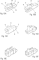
- FIG 15A An embodiment of an activator 12 is shown on a spring element 13, which is designed as in the previous embodiment, wherein the spring element 13 has a first leg 14 for fixing the activator 12 and a second leg 15 for fixing to a guide rail 8.
- the spring element 13 has a stop 20 to limit the movement of the activator 12 at least outwards, i.e. towards the driver 16.
- the stop 20 is formed on an angular web 22, which passes through an opening 21 in the leg 14.
- the stop 20 prevents the movement of the activator 12 from occurring in the event of a strong tensile load on the guide rail 8 ( Figure 14A ) the activator 12 presses too hard against the driver 16, so that the spring element 13 could deform plastically or the driver 16 could be damaged.
- the stop 20 can prevent the leg 14 from twisting relative to the leg 15, thus preventing the activator from deflecting upwards and/or downwards in this case. This lateral fixation is particularly evident in the following embodiments with a double stop 30.
- FIG. 15B a modified embodiment of the stop 20 is shown, which is formed integrally with the leg 15 on a modified web.
- a stop 30 is provided which limits the movement of the leg 14 with the activator 12.
- the stop 30 is formed integrally with the leg 15 as an angle.
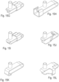
- FIGS 15D to 15L show different designs of a U-shaped spring element, each of which has at least one integrally formed stop for limiting the movement of the activator 12 on the leg 15.
- the skilled person can implement such a stop in various ways.
- FIG 15M A modified embodiment of a spring element is shown, which is designed as a web and has a first section 14a parallel to the longitudinal direction, to which the activator 12 is fixed.
- a second section 14b is inclined to the longitudinal direction, and a third section 14c is aligned parallel to the longitudinal direction and fixed to the guide rail 8.
- the section 14c is fixed closer to the rear end of the guide rail 8 than the activator 12 is arranged, in order to cause the activator 12 to be pressed towards the driver 16 when the guide rail 8 is subjected to tensile load.
- Figures 15N to 15T show variants of a spring element with which this function can also be realized, i.e. with which the activator 12 is pressed against the driver 16 when there is a tensile load on the guide rail.
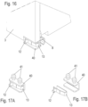
- FIG 16 A modified embodiment of an activator 12 with a spring element 13 is shown, which is not fixed to the guide rail 8, but rather to the drawer 3.
- a holder 40 is provided on the drawer 3, which is U-shaped and in which the U-shaped spring element 13 with the activator 12 is arranged.
- the U-shaped holder 40 is shown, in which the spring element 13 with the activator 12 is accommodated.
- Two dowels 41 are formed on the holder 40, which, in the mounted position, engage in openings in the drawer 3.
- the activator 12 therefore does not have to be fixed directly to the guide rail 8, but can also be held on a drawer 3.
- the spring element can also be detachably or permanently attached to the movable furniture part directly, by gluing or locking and/or by means of other connecting elements.
- the driver 16 and the activator 12 are part of a locking system that ensures that only one of the drawers 3 can be in an open position at a time in order to prevent the furniture 1 from tipping over.
- the activator 12 and the driver 16 in a self-closing or ejection device
- the activator 12 is resiliently mounted on a spring element 13 in order to reinforce the engagement with the driver 16 in the event of a tensile load.
Landscapes
- Engineering & Computer Science (AREA)
- Mechanical Engineering (AREA)
- Drawers Of Furniture (AREA)
- Closing And Opening Devices For Wings, And Checks For Wings (AREA)
Applications Claiming Priority (2)
| Application Number | Priority Date | Filing Date | Title |
|---|---|---|---|
| DE102021120931.5A DE102021120931A1 (de) | 2021-08-11 | 2021-08-11 | Vorrichtung zum Halten, Abbremsen oder Beschleunigen eines bewegbaren Möbelteils, Schließsystem und Möbel |
| PCT/EP2022/072316 WO2023017017A1 (de) | 2021-08-11 | 2022-08-09 | VORRICHTUNG ZUM HALTEN, ABBREMSEN ODER BESCHLEUNIGEN EINES BEWEGBAREN MÖBELTEILS, SCHLIEßSYSTEM UND MÖBEL |
Publications (3)
| Publication Number | Publication Date |
|---|---|
| EP4384048A1 EP4384048A1 (de) | 2024-06-19 |
| EP4384048C0 EP4384048C0 (de) | 2025-05-21 |
| EP4384048B1 true EP4384048B1 (de) | 2025-05-21 |
Family
ID=83151439
Family Applications (1)
| Application Number | Title | Priority Date | Filing Date |
|---|---|---|---|
| EP22762058.0A Active EP4384048B1 (de) | 2021-08-11 | 2022-08-09 | Möbel mit einer vorrichtung zum halten, abbremsen oder beschleunigen eines bewegbaren möbelteils |
Country Status (8)
| Country | Link |
|---|---|
| US (1) | US12478180B2 (pl) |
| EP (1) | EP4384048B1 (pl) |
| CN (1) | CN117729865A (pl) |
| CA (1) | CA3224967A1 (pl) |
| DE (1) | DE102021120931A1 (pl) |
| ES (1) | ES3032769T3 (pl) |
| PL (1) | PL4384048T3 (pl) |
| WO (1) | WO2023017017A1 (pl) |
Family Cites Families (29)
| Publication number | Priority date | Publication date | Assignee | Title |
|---|---|---|---|---|
| DE3834721A1 (de) * | 1988-10-12 | 1990-04-19 | Schock Metallwerk | Auszugfuehrung mit selbsttaetig erreichbarer einschiebeendstellung |
| DE10157754A1 (de) * | 2001-11-27 | 2003-06-26 | Grass Gmbh Hoechst | Vorrichtung zum Öffnen und Schließen eines beweglichen Möbelteils |
| HK1073209A2 (en) * | 2005-06-10 | 2005-09-23 | 科誉国际(亚洲)有限公司 | Assembleable and detachable metal storage cabinet |
| DE102006016102B4 (de) * | 2006-04-04 | 2019-01-31 | Grass Gmbh | Möbel mit wenigstens zwei gegenüber einem ersten Möbelteil motorisch bewegbaren weiteren Möbelteilen |
| DE202008003328U1 (de) | 2007-10-02 | 2009-02-12 | Paul Hettich Gmbh & Co. Kg | Auszugsführung mit einer Selbsteinzugsvorrichtung |
| CN102065726A (zh) * | 2008-07-24 | 2011-05-18 | 格拉斯美国公司 | 用于抽屉滑动装置的控制机构 |
| DE102009003362B4 (de) | 2009-01-19 | 2023-01-19 | Paul Hettich Gmbh & Co. Kg | Vorrichtung zum Öffnen und/oder Schließen von Schubkästen und Verfahren zu ihrer Kalibrierung |
| DE202009005119U1 (de) * | 2009-08-07 | 2010-12-30 | Paul Hettich Gmbh & Co. Kg | Auszugsführung |
| DE102009049429B4 (de) * | 2009-10-14 | 2014-08-21 | Karl Simon Gmbh & Co. Kg | Schiebeanordnung |
| DE102010036903B4 (de) * | 2010-02-26 | 2020-09-10 | Paul Hettich Gmbh & Co. Kg | Ausstoßvorrichtung und Auszugssystem |
| JP5632645B2 (ja) * | 2010-05-07 | 2014-11-26 | 株式会社ニフコ | 引込装置及びそれに用いられる引込本体 |
| DE102010017132B4 (de) * | 2010-05-28 | 2020-10-01 | Paul Hettich Gmbh & Co. Kg | Schrankmöbel mit einem Frontschubkasten und einem Innenschubkasten |
| CA2708700C (en) * | 2010-06-29 | 2016-11-22 | Wesko Systems Limited | Releasable tenon for locking system |
| DE102011050445A1 (de) * | 2010-06-30 | 2012-01-05 | Paul Hettich Gmbh & Co. Kg | Auszugsführung für ein Möbelauszugsteil |
| DE102010017716A1 (de) * | 2010-07-02 | 2012-01-05 | Paul Hettich Gmbh & Co. Kg | Kurvenführung |
| DE202010013193U1 (de) * | 2010-12-22 | 2012-03-26 | Paul Hettich Gmbh & Co. Kg | Öffnungs- und Schließvorrichtung für bewegbare Möbelteile und Ausstoßvorrichtung |
| DE102013102944B4 (de) * | 2012-10-12 | 2024-05-16 | Paul Hettich Gmbh & Co. Kg | Auszugsführung |
| AT514064B1 (de) * | 2013-04-12 | 2014-10-15 | Blum Gmbh Julius | Antriebsvorrichtung für ein bewegbares Möbelteil |
| DE102014105553A1 (de) * | 2014-04-17 | 2015-10-22 | Hettich-Heinze Gmbh & Co. Kg | Beschleunigungs- oder Bremsvorrichtung |
| KR102358755B1 (ko) * | 2015-11-04 | 2022-02-07 | 엘지전자 주식회사 | 냉장고 |
| DE102016116449A1 (de) * | 2016-09-02 | 2018-03-08 | Paul Hettich Gmbh & Co. Kg | Selbsteinzugs- und Dämpfungsvorrichtung für ein Schubelement und Möbel oder Haushaltsgerät mit mindestens einem Schubelement |
| DE102017107461A1 (de) * | 2017-04-06 | 2018-10-11 | Karl Simon Gmbh & Co. Kg | Bewegungsanordnung |
| TWI638624B (zh) * | 2017-06-23 | 2018-10-21 | 川湖科技股份有限公司 | 滑軌總成 |
| US10264698B2 (en) * | 2017-08-25 | 2019-04-16 | Facebook, Inc. | Systems and methods for mounting assembly pull-handles |
| TWI678171B (zh) * | 2018-09-26 | 2019-12-01 | 南俊國際股份有限公司 | 外置式緩歸滑軌 |
| DE102019200980A1 (de) * | 2019-01-25 | 2020-07-30 | Schock Metallwerk Gmbh | Führungsvorrichtung und Führungssystem |
| DE102019104421A1 (de) * | 2019-02-21 | 2020-08-27 | Paul Hettich Gmbh & Co. Kg | Auszugsführung |
| US11185161B2 (en) * | 2020-02-27 | 2021-11-30 | Toshiba Tec Kabushiki Kaisha | Soft close print paper drawer |
| DE102020127404A1 (de) | 2020-10-17 | 2022-04-21 | Paul Hettich Gmbh & Co. Kg | Schließvorrichtung für bewegbare Möbelteile und Verfahren zum Verriegeln mindestens eines bewegbaren Möbelteils |
-
2021
- 2021-08-11 DE DE102021120931.5A patent/DE102021120931A1/de active Pending
-
2022
- 2022-08-09 ES ES22762058T patent/ES3032769T3/es active Active
- 2022-08-09 EP EP22762058.0A patent/EP4384048B1/de active Active
- 2022-08-09 WO PCT/EP2022/072316 patent/WO2023017017A1/de not_active Ceased
- 2022-08-09 CN CN202280052398.6A patent/CN117729865A/zh active Pending
- 2022-08-09 US US18/294,205 patent/US12478180B2/en active Active
- 2022-08-09 CA CA3224967A patent/CA3224967A1/en active Pending
- 2022-08-09 PL PL22762058.0T patent/PL4384048T3/pl unknown
Also Published As
| Publication number | Publication date |
|---|---|
| WO2023017017A1 (de) | 2023-02-16 |
| US20240341469A1 (en) | 2024-10-17 |
| DE102021120931A1 (de) | 2023-02-16 |
| CN117729865A (zh) | 2024-03-19 |
| ES3032769T3 (en) | 2025-07-24 |
| PL4384048T3 (pl) | 2025-08-18 |
| EP4384048C0 (de) | 2025-05-21 |
| US12478180B2 (en) | 2025-11-25 |
| EP4384048A1 (de) | 2024-06-19 |
| CA3224967A1 (en) | 2023-02-16 |
Similar Documents
| Publication | Publication Date | Title |
|---|---|---|
| AT508515B1 (de) | Auszugsführung | |
| DE2719325C2 (de) | Verschluss für Sicherheitsgurte | |
| EP0421458B1 (de) | Schublade | |
| EP2465381B1 (de) | Ausstoßmechanismus | |
| EP1816927B1 (de) | Ausziehführungsgarnitur für Schubladen | |
| EP2373195B1 (de) | Selbsteinzugsvorrichtung und auszugsführung | |
| EP3449077B1 (de) | Ausstossvorrichtung für ein bewegbares möbelteil und möbel | |
| AT508139B1 (de) | Möbelantrieb mit touch-latch-vorrichtung | |
| EP1921948A1 (de) | Verriegelbare ausstossvorrichtung | |
| EP2174572A1 (de) | Öffnungs- und Schließvorrichtung für ein Schubelement | |
| AT507656A4 (de) | Anordnung zum verriegeln und ausstossen eines möbelteils | |
| DE2933018A1 (de) | Gurtschnalle fuer kraftfahrzeug- sicherheitsgurte | |
| DE4421688C1 (de) | Gurtverschluß | |
| EP2208439A1 (de) | Vorrichtung zum Öffnen und/oder Schließen von Schubkästen und Verfahren zu ihrer Kalibrierung | |
| EP3341545B1 (de) | Vorrichtung zum positionieren von zwei schiebetüren und möbel | |
| AT514666B1 (de) | Führungsvorrichtung für bewegbare Möbelteile | |
| EP4082394A1 (de) | Ladenschiene für eine schubladenausziehführung | |
| EP2401941B1 (de) | Kurvenführung | |
| WO2012110373A1 (de) | Vorrichtung zur verriegelung relativ zueinander beweglicher teile | |
| WO2015003994A1 (de) | Auszugsführung für einen schubkasten | |
| EP4384048B1 (de) | Möbel mit einer vorrichtung zum halten, abbremsen oder beschleunigen eines bewegbaren möbelteils | |
| EP3189749B1 (de) | Ausziehführung für ein bewegbares möbelteil | |
| DE2752091A1 (de) | Gurtschloss fuer sicherheitsgurte | |
| DE102010015969A1 (de) | Auszugsführung | |
| EP1682737A1 (de) | Gehäuse- und verschlusselement mit überschlagsicherung |
Legal Events
| Date | Code | Title | Description |
|---|---|---|---|
| STAA | Information on the status of an ep patent application or granted ep patent |
Free format text: STATUS: UNKNOWN |
|
| STAA | Information on the status of an ep patent application or granted ep patent |
Free format text: STATUS: THE INTERNATIONAL PUBLICATION HAS BEEN MADE |
|
| PUAI | Public reference made under article 153(3) epc to a published international application that has entered the european phase |
Free format text: ORIGINAL CODE: 0009012 |
|
| STAA | Information on the status of an ep patent application or granted ep patent |
Free format text: STATUS: REQUEST FOR EXAMINATION WAS MADE |
|
| 17P | Request for examination filed |
Effective date: 20240307 |
|
| AK | Designated contracting states |
Kind code of ref document: A1 Designated state(s): AL AT BE BG CH CY CZ DE DK EE ES FI FR GB GR HR HU IE IS IT LI LT LU LV MC MK MT NL NO PL PT RO RS SE SI SK SM TR |
|
| DAV | Request for validation of the european patent (deleted) | ||
| DAX | Request for extension of the european patent (deleted) | ||
| GRAP | Despatch of communication of intention to grant a patent |
Free format text: ORIGINAL CODE: EPIDOSNIGR1 |
|
| STAA | Information on the status of an ep patent application or granted ep patent |
Free format text: STATUS: GRANT OF PATENT IS INTENDED |
|
| INTG | Intention to grant announced |
Effective date: 20250103 |
|
| GRAS | Grant fee paid |
Free format text: ORIGINAL CODE: EPIDOSNIGR3 |
|
| GRAA | (expected) grant |
Free format text: ORIGINAL CODE: 0009210 |
|
| STAA | Information on the status of an ep patent application or granted ep patent |
Free format text: STATUS: THE PATENT HAS BEEN GRANTED |
|
| AK | Designated contracting states |
Kind code of ref document: B1 Designated state(s): AL AT BE BG CH CY CZ DE DK EE ES FI FR GB GR HR HU IE IS IT LI LT LU LV MC MK MT NL NO PL PT RO RS SE SI SK SM TR |
|
| REG | Reference to a national code |
Ref country code: GB Ref legal event code: FG4D Free format text: NOT ENGLISH |
|
| REG | Reference to a national code |
Ref country code: CH Ref legal event code: EP |
|
| REG | Reference to a national code |
Ref country code: DE Ref legal event code: R096 Ref document number: 502022004052 Country of ref document: DE |
|
| REG | Reference to a national code |
Ref country code: IE Ref legal event code: FG4D Free format text: LANGUAGE OF EP DOCUMENT: GERMAN |
|
| U01 | Request for unitary effect filed |
Effective date: 20250528 |
|
| U07 | Unitary effect registered |
Designated state(s): AT BE BG DE DK EE FI FR IT LT LU LV MT NL PT RO SE SI Effective date: 20250606 |
|
| REG | Reference to a national code |
Ref country code: ES Ref legal event code: FG2A Ref document number: 3032769 Country of ref document: ES Kind code of ref document: T3 Effective date: 20250724 |
|
| U20 | Renewal fee for the european patent with unitary effect paid |
Year of fee payment: 4 Effective date: 20250826 |
|
| PGFP | Annual fee paid to national office [announced via postgrant information from national office to epo] |
Ref country code: ES Payment date: 20250917 Year of fee payment: 4 |
|
| PG25 | Lapsed in a contracting state [announced via postgrant information from national office to epo] |
Ref country code: NO Free format text: LAPSE BECAUSE OF FAILURE TO SUBMIT A TRANSLATION OF THE DESCRIPTION OR TO PAY THE FEE WITHIN THE PRESCRIBED TIME-LIMIT Effective date: 20250821 Ref country code: GR Free format text: LAPSE BECAUSE OF FAILURE TO SUBMIT A TRANSLATION OF THE DESCRIPTION OR TO PAY THE FEE WITHIN THE PRESCRIBED TIME-LIMIT Effective date: 20250822 |
|
| PGFP | Annual fee paid to national office [announced via postgrant information from national office to epo] |
Ref country code: PL Payment date: 20250725 Year of fee payment: 4 Ref country code: TR Payment date: 20250808 Year of fee payment: 4 |
|
| PG25 | Lapsed in a contracting state [announced via postgrant information from national office to epo] |
Ref country code: HR Free format text: LAPSE BECAUSE OF FAILURE TO SUBMIT A TRANSLATION OF THE DESCRIPTION OR TO PAY THE FEE WITHIN THE PRESCRIBED TIME-LIMIT Effective date: 20250521 |
|
| PG25 | Lapsed in a contracting state [announced via postgrant information from national office to epo] |
Ref country code: RS Free format text: LAPSE BECAUSE OF FAILURE TO SUBMIT A TRANSLATION OF THE DESCRIPTION OR TO PAY THE FEE WITHIN THE PRESCRIBED TIME-LIMIT Effective date: 20250821 |
|
| PGFP | Annual fee paid to national office [announced via postgrant information from national office to epo] |
Ref country code: CZ Payment date: 20250729 Year of fee payment: 4 |
|
| PG25 | Lapsed in a contracting state [announced via postgrant information from national office to epo] |
Ref country code: IS Free format text: LAPSE BECAUSE OF FAILURE TO SUBMIT A TRANSLATION OF THE DESCRIPTION OR TO PAY THE FEE WITHIN THE PRESCRIBED TIME-LIMIT Effective date: 20250921 |
|
| PG25 | Lapsed in a contracting state [announced via postgrant information from national office to epo] |
Ref country code: SM Free format text: LAPSE BECAUSE OF FAILURE TO SUBMIT A TRANSLATION OF THE DESCRIPTION OR TO PAY THE FEE WITHIN THE PRESCRIBED TIME-LIMIT Effective date: 20250521 |
|
| PG25 | Lapsed in a contracting state [announced via postgrant information from national office to epo] |
Ref country code: SK Free format text: LAPSE BECAUSE OF FAILURE TO SUBMIT A TRANSLATION OF THE DESCRIPTION OR TO PAY THE FEE WITHIN THE PRESCRIBED TIME-LIMIT Effective date: 20250521 |
|
| REG | Reference to a national code |
Ref country code: CH Ref legal event code: H13 Free format text: ST27 STATUS EVENT CODE: U-0-0-H10-H13 (AS PROVIDED BY THE NATIONAL OFFICE) Effective date: 20260324 |
|
| PLBE | No opposition filed within time limit |
Free format text: ORIGINAL CODE: 0009261 |
|
| STAA | Information on the status of an ep patent application or granted ep patent |
Free format text: STATUS: NO OPPOSITION FILED WITHIN TIME LIMIT |
|
| PG25 | Lapsed in a contracting state [announced via postgrant information from national office to epo] |
Ref country code: MC Free format text: LAPSE BECAUSE OF FAILURE TO SUBMIT A TRANSLATION OF THE DESCRIPTION OR TO PAY THE FEE WITHIN THE PRESCRIBED TIME-LIMIT Effective date: 20250521 |
|
| REG | Reference to a national code |
Ref country code: CH Ref legal event code: L10 Free format text: ST27 STATUS EVENT CODE: U-0-0-L10-L00 (AS PROVIDED BY THE NATIONAL OFFICE) Effective date: 20260402 |
|
| PG25 | Lapsed in a contracting state [announced via postgrant information from national office to epo] |
Ref country code: CH Free format text: LAPSE BECAUSE OF NON-PAYMENT OF DUE FEES Effective date: 20250831 |
|
| 26N | No opposition filed |
Effective date: 20260224 |