EP4352002B1 - Châssis d'un escalier roulant ou d'un trottoir roulant - Google Patents
Châssis d'un escalier roulant ou d'un trottoir roulant Download PDFInfo
- Publication number
- EP4352002B1 EP4352002B1 EP22731217.0A EP22731217A EP4352002B1 EP 4352002 B1 EP4352002 B1 EP 4352002B1 EP 22731217 A EP22731217 A EP 22731217A EP 4352002 B1 EP4352002 B1 EP 4352002B1
- Authority
- EP
- European Patent Office
- Prior art keywords
- support structure
- anchor
- devices
- supporting structure
- anchor device
- Prior art date
- Legal status (The legal status is an assumption and is not a legal conclusion. Google has not performed a legal analysis and makes no representation as to the accuracy of the status listed.)
- Active
Links
Images

Classifications
-
- A—HUMAN NECESSITIES
- A62—LIFE-SAVING; FIRE-FIGHTING
- A62B—DEVICES, APPARATUS OR METHODS FOR LIFE-SAVING
- A62B35/00—Safety belts or body harnesses; Similar equipment for limiting displacement of the human body, especially in case of sudden changes of motion
- A62B35/0043—Lifelines, lanyards, and anchors therefore
- A62B35/0068—Anchors
-
- B—PERFORMING OPERATIONS; TRANSPORTING
- B66—HOISTING; LIFTING; HAULING
- B66B—ELEVATORS; ESCALATORS OR MOVING WALKWAYS
- B66B23/00—Component parts of escalators or moving walkways
-
- B—PERFORMING OPERATIONS; TRANSPORTING
- B66—HOISTING; LIFTING; HAULING
- B66B—ELEVATORS; ESCALATORS OR MOVING WALKWAYS
- B66B29/00—Safety devices of escalators or moving walkways
Definitions
- the present invention relates to a supporting structure of an escalator or a moving walkway.
- An escalator or moving walkway is a passenger transport system with movable surface segments that are connected to form an endless chain and can be moved by a drive along a guide to transport people.
- the surface segments are arranged almost seamlessly one behind the other, at least on the upper side of the passenger transport system.
- the passenger transport system has two end sections and a middle section. At least at the end sections, the passenger transport system is connected to a structure. At the end sections, the surface segments appear and disappear under a comb plate and an adjoining floor covering. The end sections are usually aligned horizontally.
- the end sections are arranged at different levels of the structure.
- the central section runs at an angle to the horizontal and connects the levels.
- the surface segments of the escalator form steps.
- the escalator can be referred to as an escalator.
- Both the escalator and the moving walkway have a supporting structure.
- the supporting structure can be designed as a truss.
- the individual components of the passenger transport system such as the guide, the drive, balustrades, handrails and Cladding is connected to the supporting structure.
- the supporting structure is usually prefabricated and lifted into the building. Once the end sections of the supporting structure are connected to the structure, additional components are installed and the passenger transport system is completed and ready for operation. In particular, balustrades are often installed only after the supporting structure has been anchored in the structure.
- fitters To assemble the components, fitters must access the supporting structure. Since the central section of the personnel transport system often runs freely through the air, the fitters require fall protection.
- the fitters can secure themselves, for example, with large hooks or carabiners directly in the supporting structure or to structures in the building.
- temporary maintenance railings can be clamped to the supporting structure with special clamping devices.
- the fitters can also use the temporary maintenance railings to attach their personal protective equipment.
- the personal protective equipment usually consists of a harness worn on the body and a longer piece of rope attached to it, the end of which can be hooked safely, quickly and easily to a suitable location using a snap hook, for example.
- the temporary maintenance railings can be gradually removed as the balustrades are installed.
- Securing personal protective equipment to structures in the building that are not specifically designed for this purpose, or to structures on the supporting structure that are not specifically designed for this purpose, can be complex and can also pose a risk of inappropriate fall protection.
- Installing and then removing temporary maintenance railings can require additional effort. Since temporary maintenance railings are loose parts during installation or removal, they can be dropped. Parts of the temporary maintenance railing can cause considerable damage if dropped.
- clamping devices with different clamping cross-sections or clamping surfaces are required for different types of supporting structures to ensure flat contact with the respective supporting structure.
- WO 2019/185573 A1 describes a fastening device for attaching a temporary maintenance railing to a supporting structure of a passenger transport system.
- EP 1 108 675 B1 describes a working method and a protection system for assembly personnel working on a passenger conveyor system.
- a supporting structure for an escalator or moving walkway wherein at least two anchoring devices for personal protective equipment are arranged in a central region of the supporting structure, spaced apart from one another by a maximum safety distance and firmly connected to the supporting structure.
- Anchoring devices also referred to as anchor points, are specially created locations to which personal protective equipment can be securely, quickly, and easily attached.
- the anchoring devices typically have a structure with an eyelet formed thereon, so that the personal protective equipment can be quickly and securely attached to it, but also quickly detached again.
- the upper chords, lower chords, struts, uprights, and cross braces can be L-profiles made of metal.
- the upper chords, lower chords, struts, uprights, and cross braces can be connected to one another via gusset plates.
- the top chords, bottom chords, struts, uprights, and cross braces can be welded, bolted, pinned, and/or riveted.
- a central section of the supporting structure can be located between two end sections of the supporting structure.
- the central section In an escalator, the central section is aligned diagonally to the horizontal in one installed position of the supporting structure.
- the central section In a moving walk, the central section can run horizontally or diagonally upwards or downwards.
- the end sections of both an escalator and a moving walk can generally be aligned horizontally.
- the supporting structure can have connection points to a building at the end sections. Lifting points for raising the supporting structure can also be arranged at the end sections.
- An anchor device for personal protective equipment is specifically dimensioned for this purpose in accordance with applicable standards and regulations.
- the anchor device can, for example, comply with the European standard EN 365 and/or EN 795.
- the anchor device for personal protective equipment is a specially designed fixed device that is specifically intended for the purpose of fall protection using personal protective equipment on the supporting structure.
- the anchor device for personal protective equipment is not an installation point for components of the escalator or moving walkway. It is also not used for attaching lifting equipment, such as the lifting points described above.
- the anchor device is dimensioned such that it can absorb the forces occurring during a standard fall without damage and transfer them to the supporting structure.
- the anchor device can be designed for a load of 16 kilonewtons.
- the anchor device can also be dimensioned for greater forces.
- the anchor devices presented here remain on the supporting structure even after the components of the passenger transport system have been installed.
- the anchor device has an eyelet.
- the eyelet can be a through-hole, an opening, or a hole into which at least one lanyard of the personal protective equipment can be hooked.
- the eyelet can also be large enough to allow two lanyards to be hooked in by different people simultaneously.
- the eyelet can be regular or irregular in shape.
- the anchorage device can be highlighted in a signal color or a color that contrasts with the base color of the supporting structure, so that it can be quickly and easily identified by the installation personnel being secured. This prevents the anchorage from being suspended at an inappropriate location on the supporting structure.
- anchorage devices permanently attached to the supporting structure, a technician can immediately protect themselves against falls when entering the supporting structure without first having to search for a suitable location on the supporting structure or building or first erect a temporary maintenance railing.
- PPE personal protective equipment
- PPE includes, for example, a full body harness and a fall arrester with two separate lanyards and at least one energy-absorbing element.
- the lanyards can be retractable and extendable, for example.
- the energy-absorbing element can partially absorb the kinetic energy of a falling body, thus preventing injuries.
- the anchor devices can be cut from a sheet material.
- Each anchor device can have a stiffening area for locally stiffening the supporting structure and a tab with an eyelet.
- a sheet material can be a thick metal sheet.
- the sheet material can be sheet steel, for example.
- the anchor devices can be burned, punched, lasered, waterjet cut, or milled from the sheet material, for example.
- a stiffening area can, at least in part, represent a profile of the structural component to which the anchor device is arranged.
- the stiffening area can be welded to the structural component.
- the stiffening area can enlarge a force introduction area of the structural component to introduce the fall energy, so that the supporting structure is not damaged if a mechanic falls.
- the stiffening area can, for example, have two V-shaped legs, so that the anchor device resembles a butterfly with outstretched wings.
- the legs can enlarge the force introduction area along a direction of extension of the structural component.
- a tab can protrude from the stiffening area.
- the tab can protrude beyond the structural component.
- the tab can be arranged centrally between the legs.
- the tab can be tongue-shaped.
- One end of the tab can be rounded.
- the eyelet can be a cutout through the tab.
- the eyelet can be circular or oval, for example.
- the eyelet can also be triangular with rounded corners.
- the eyelet can be large enough to allow two connecting devices to be attached simultaneously.
- the tab and/or the legs can bend in the event of a fall and thus absorb fall energy. This can protect the structural component from overload.
- At least one color-coded anchor device can be arranged at at least one of the end areas, which are horizontally aligned in the installed position. It is firmly connected to the supporting structure and spaced at a maximum distance equal to the safety distance from an adjacent anchor device.
- the end areas of the supporting structure can extend beyond an edge of the structure. In this case, a fall hazard may already exist at the transition from the end area to the middle area.
- the pawl In the locked position, the pawl can be arranged transversely to the hole and rest against a rear side of the anchor device. This prevents the pawl anchor from being pulled out of the anchor device.
- the spring can be compressed and the pawl can be moved back to the unlocked position. The pawl anchor can then be removed from the anchor device.
- the anchor device can be located on the underside of an upper chord of the structure. Locating it on the underside can prevent lateral loading of the anchor device in the event of a fall.
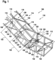
- Fig. 1 shows a representation of a supporting structure 100 according to an exemplary embodiment.
- the supporting structure 100 is a truss consisting of upper chords 102, lower chords 104, struts 106 and uprights 108, and cross struts 110.
- the upper chords 102 and lower chords 104 run essentially parallel to one another.
- the lower chords 104 are connected to one another by cross struts 110.
- the cross struts 110 are arranged perpendicular to the lower chords 104.
- the struts 106 are arranged diagonally to the upper chords 102 and lower chords 104 and each connect one of the upper chords 102 to one of the lower chords 104.
- the uprights 108 are arranged perpendicular to the upper chords 102 and lower chords 104 and each connect one of the upper chords 102 to one of the lower chords 104.
- the uprights 108 are connected by further cross struts 110.
- the supporting structure 100 has two end regions 112 and a central region 114.
- half of a supporting structure 100 of an escalator 116 is shown. Its central region 114 is aligned obliquely to the end regions 112 in order to overcome a height difference between the two levels connected by the escalator 116.
- the end regions 112 are aligned horizontally.
- the supporting structure 100 has a kink.
- the central region 114 can be arranged.
- stop devices 118 for personal protective equipment 130 (this is shown in the Figure 1 (shown only schematically and without an installer) are firmly connected to the supporting structure 100.
- the anchor devices 118 are dimensioned and designed in such a way that they meet the relevant standards and regulations with regard to their strength.
- the anchor devices 118 are clearly color-coded.
- the anchor devices 118 each have an eyelet 120 for at least one connecting means 123 of the personal protective equipment 130.
- the anchor devices 118 remain on the supporting structure 100 even after the completion of the escalator 116.
- the anchor devices 118 are arranged at a maximum safety distance of 122 from each other.
- the safety distance 122 is smaller than the average arm span of an average person.
- the average arm span can be specified in relevant standards and regulations.
- the anchor devices 118 are welded to the supporting structure 100. This integral connection allows the forces generated in the event of a fall to be safely transmitted into the supporting structure 100. The welding also prevents the anchor devices 118 from being accidentally unscrewed.
- the anchor devices 118 are arranged on both sides of the supporting structure 100.
- the anchor devices 118 are arranged to the right and left of the supporting structure 100. This allows the installer to secure himself on both sides simultaneously. The fall height can be reduced in this way, since the first lanyard to be tightened always slows the fall.
- the stop devices 118 are arranged in pairs opposite one another. This allows the technician to always reach at least three of the stop devices 118 simultaneously. If two technicians are working on the escalator 116 at the same time, they can easily pass each other, since one of the technicians on each side can be secured while passing. Once the technicians have passed each other, they can secure themselves again on both sides.
- the anchor devices 118 are arranged on the upper chords 102.
- the anchor devices 118 on the upper chords 102 are easily accessible to the technician because they are located at chest height while the technician is standing. By securing the upper chord 102, the fall height can be reduced.
- the upper chords 102 are sufficiently dimensioned to absorb any resulting fall energy.
- Fig. 2 shows a representation of a stop device 118 on a supporting structure 100 according to an embodiment.
- the stop device 118 corresponds in Essentially the Fig. 1 shown stop devices.
- the escalator 116 is already partially assembled.
- a balustrade 200 is attached to the upper chord 102 using balustrade clamps 202.
- the balustrade 200 provides lateral fall protection.
- the balustrade clamp 202 is screwed to the upper chord 102 and securely clamps the balustrade 200 between its clamping jaws.
- the stop device 118 is arranged between a lower edge of the balustrade 200 and the upper chord 102.
- the anchor devices 300 are arranged on an underside of the upper chord 102.
- the anchor device 302 can be anchored from below or diagonally below in the anchor device 300 and can be removed from the anchor device 300 again after use. from below, lateral shear loads on the anchor devices 302 can be avoided in the event of a fall.
- the shaft 310 is pushed further into the hole 308, the pawl 306, which is thus relieved of load, is realigned longitudinally by an integrated mechanism and pulled out of the hole 308 together with the shaft 310.
- the thread 314 is designed as a blind hole and is arranged in a stiffening region 124 of the anchor device 300 in order to avoid any notch effects in the supporting structure 100.
- the stiffening region 124 is in particular provided with welded to the supporting structure 100 and has a greater thickness than the depth of the blind hole.
- This system makes it possible to hook into the next anchorage device 118 while wearing personal protective equipment 130 without having to unhook from the current anchorage device 118. This makes it possible to secure oneself from one anchorage device 118 to the next along the escalator 116. This ensures compliance with the defined safety concept for the installers, which stipulates that they may only enter the unfinished escalator 116 or the unfinished moving walkway while secured against falls.
- the stop devices 118 are preferably welded to the upper chord 102 of the truss 100, or to other escalator structural elements, for example, soldered or glued, provided that these elements withstand the test forces required by the standards.
- the illustrated design enables several people to secure themselves on the escalator 116 at the same time with their personal protective equipment 130 without any additional effort.
- the anchor devices 118 are highlighted by color or other markings to prevent accidental securing to components not intended for this purpose.
- anchor devices 118 are pre-assembled at the factory and can therefore be used immediately for fall protection without the need for complex assembly work prior to installation of the escalator 116.
- the anchor devices 118 can be used immediately for fall protection if no anchor devices are provided by the building.
- the stop devices 118 can be used both for the balustrade construction and for all subsequent repairs or modernizations of the systems, since the stop devices 118 remain installed on the escalator 116.
- the stop devices 118 themselves can be manufactured, for example, by laser cutting, flame cutting, or waterjet cutting. Likewise, the stop devices 118 can be manufactured as a gravity-cast component or using another manufacturing process.
- the illustrated anchoring devices 118 are designed for connection by welding to the upper chord 102 in such a way that they can be used for all product types.
- the size and shape of the opening for hanging the personal protective equipment 130 can vary to accommodate one or more snap or screw carabiners.
- the permanently installed stop devices 118 described in this document allow for easy handling and can be used on all escalator types. They are permanently installed on their supporting structure 100, can also be used for repairs or modernizations, and are cost-effective to manufacture.
- the use of the permanently installed stop devices 118 presented here can improve occupational safety and increase work efficiency.
Landscapes
- Health & Medical Sciences (AREA)
- General Health & Medical Sciences (AREA)
- Business, Economics & Management (AREA)
- Emergency Management (AREA)
- Escalators And Moving Walkways (AREA)
Claims (15)
- Structure porteuse (100) d'un escalier roulant (116) ou d'un trottoir roulant, dans laquelle au moins deux dispositifs de butée (118) pour équipement de protection individuelle (130), espacés l'un de l'autre au maximum d'une distance de sécurité (122) et soudés, brasés ou rivetés avec la structure porteuse (100), sont disposés sur une zone centrale (114) de la structure porteuse (100).
- Structure porteuse (100) selon la revendication 1, dans laquelle les dispositifs de butée (118) sont identifiés par un code couleur.
- Structure porteuse (100) selon l'une des revendications précédentes, dans laquelle les dispositifs de butée (118) sont disposés sur des côtés opposés de la structure porteuse (100).
- Structure porteuse (100) selon l'une des revendications précédentes, dans laquelle, sur au moins une zone d'extrémité (112) de la structure porteuse (100), est disposé au moins un dispositif d'ancrage (300), relié de manière fixe à la structure porteuse (100) et identifié par un code couleur, pour un dispositif de butée (302) pour l'équipement de protection individuelle (130), dans laquelle le dispositif d'ancrage (300) est espacé au maximum de la distance de sécurité (122) d'un dispositif de butée (118) voisin.
- Structure porteuse (100) selon la revendication 4, dans laquelle au moins deux dispositifs d'ancrage (300) sont disposés dans la zone d'extrémité (112) sur des côtés opposés de la structure porteuse (100).
- Structure porteuse (100) selon l'une des revendications 4 à 5, dans laquelle le dispositif d'ancrage (300) présente un filetage (314) pour un dispositif de butée (302) réalisé sous la forme d'un œillet vissé (312).
- Structure porteuse (100) selon l'une des revendications 4 à 6, dans laquelle le dispositif d'ancrage (300) présente un trou (308) pour un dispositif de butée (302) réalisé sous la forme d'un ancrage à cliquet (304).
- Structure porteuse (100) selon l'une des revendications 4 à 7, dans laquelle le dispositif d'ancrage (300) est disposé sur une face inférieure d'une membrure supérieure (102) de la structure porteuse (100).
- Structure porteuse (100) selon l'une des revendications précédentes, dans laquelle les dispositifs de butée (118) et/ou les dispositifs d'ancrage (300) sont disposés par paires en vis-à-vis.
- Structure porteuse (100) selon l'une des revendications 4 à 9, dans laquelle l'au moins un dispositif d'ancrage (300) est soudé à la structure porteuse (100).
- Structure porteuse (100) selon l'une des revendications précédentes, dans laquelle la structure porteuse (100) présente des membrures supérieures (102) et des membrures inférieures (104), et dans laquelle les dispositifs de butée (118) et/ou les dispositifs d'ancrage (300) sont disposés sur au moins l'une des membrures supérieures (102) de la structure porteuse (100).
- Structure porteuse (100) selon l'une des revendications précédentes, dans laquelle les dispositifs de butée (118) sont orientés vers un espace intérieur (128) de la structure porteuse (100).
- Structure porteuse (100) selon l'une des revendications précédentes, dans laquelle les dispositifs de butée (118) sont découpés dans un matériau en plaque et présentent chacun une zone de rigidification (124) pour la rigidification locale de la structure porteuse (100) ainsi qu'une patte (126) munie d'un œillet (120).
- Structure porteuse (100) selon la revendication 9, dans laquelle les dispositifs de butée (118) sont découpés et pliés, dans laquelle la patte (126) est orientée selon un angle par rapport à la zone de rigidification (124).
- Structure porteuse (100) selon l'une des revendications précédentes, dans laquelle au moins un dispositif de butée (118), relié de manière fixe à la structure porteuse (100) et espacé au maximum de la distance de sécurité (122) d'un dispositif de butée (118) voisin, est disposé sur au moins l'une des zones d'extrémité.
Applications Claiming Priority (2)
| Application Number | Priority Date | Filing Date | Title |
|---|---|---|---|
| EP21178925 | 2021-06-11 | ||
| PCT/EP2022/064867 WO2022258449A1 (fr) | 2021-06-11 | 2022-06-01 | Structure de maintien d'un escalier mécanique ou d'un trottoir roulant |
Publications (2)
| Publication Number | Publication Date |
|---|---|
| EP4352002A1 EP4352002A1 (fr) | 2024-04-17 |
| EP4352002B1 true EP4352002B1 (fr) | 2025-03-12 |
Family
ID=76392227
Family Applications (1)
| Application Number | Title | Priority Date | Filing Date |
|---|---|---|---|
| EP22731217.0A Active EP4352002B1 (fr) | 2021-06-11 | 2022-06-01 | Châssis d'un escalier roulant ou d'un trottoir roulant |
Country Status (8)
| Country | Link |
|---|---|
| US (1) | US20240270539A1 (fr) |
| EP (1) | EP4352002B1 (fr) |
| KR (1) | KR20240021785A (fr) |
| CN (1) | CN117460685A (fr) |
| AU (1) | AU2022290814A1 (fr) |
| BR (1) | BR112023025424A2 (fr) |
| TW (1) | TW202300431A (fr) |
| WO (1) | WO2022258449A1 (fr) |
Families Citing this family (1)
| Publication number | Priority date | Publication date | Assignee | Title |
|---|---|---|---|---|
| US20240374941A1 (en) * | 2023-05-10 | 2024-11-14 | Hog Slat, Inc. | Fall arrest system |
Citations (1)
| Publication number | Priority date | Publication date | Assignee | Title |
|---|---|---|---|---|
| WO2021175708A1 (fr) * | 2020-03-04 | 2021-09-10 | Inventio Ag | Dispositif de protection lors de travaux d'installation sur un escalier roulant ou un trottoir roulant |
Family Cites Families (6)
| Publication number | Priority date | Publication date | Assignee | Title |
|---|---|---|---|---|
| JP3454766B2 (ja) | 1999-12-16 | 2003-10-06 | 株式会社日立製作所 | 乗客コンベアの工事方法及び乗客コンベアの養生装置 |
| JP5271193B2 (ja) * | 2009-08-06 | 2013-08-21 | 三菱電機ビルテクノサービス株式会社 | 乗客コンベアの作業用安全具の支持金具 |
| JP2013245098A (ja) * | 2012-05-29 | 2013-12-09 | Hitachi Building Systems Co Ltd | 乗客コンベアの安全装置及び設置方法 |
| WO2019185573A1 (fr) | 2018-03-28 | 2019-10-03 | Inventio Ag | Dispositif de fixation destiné à fixer un garde-corps de maintenance temporaire sur une ossature porteuse d'une installation de transport de personnes |
| US11220829B2 (en) * | 2018-09-26 | 2022-01-11 | Ronald Fontes | System for the safety of workers installing escalators |
| WO2020261469A1 (fr) * | 2019-06-27 | 2020-12-30 | 三菱電機ビルテクノサービス株式会社 | Porte-outil pour escalier roulant |
-
2022
- 2022-05-27 TW TW111119858A patent/TW202300431A/zh unknown
- 2022-06-01 KR KR1020237042233A patent/KR20240021785A/ko active Pending
- 2022-06-01 CN CN202280041361.3A patent/CN117460685A/zh active Pending
- 2022-06-01 BR BR112023025424A patent/BR112023025424A2/pt unknown
- 2022-06-01 WO PCT/EP2022/064867 patent/WO2022258449A1/fr not_active Ceased
- 2022-06-01 AU AU2022290814A patent/AU2022290814A1/en active Pending
- 2022-06-01 EP EP22731217.0A patent/EP4352002B1/fr active Active
- 2022-06-01 US US18/568,473 patent/US20240270539A1/en active Pending
Patent Citations (1)
| Publication number | Priority date | Publication date | Assignee | Title |
|---|---|---|---|---|
| WO2021175708A1 (fr) * | 2020-03-04 | 2021-09-10 | Inventio Ag | Dispositif de protection lors de travaux d'installation sur un escalier roulant ou un trottoir roulant |
Also Published As
| Publication number | Publication date |
|---|---|
| KR20240021785A (ko) | 2024-02-19 |
| CN117460685A (zh) | 2024-01-26 |
| AU2022290814A1 (en) | 2023-12-21 |
| WO2022258449A1 (fr) | 2022-12-15 |
| BR112023025424A2 (pt) | 2024-02-20 |
| US20240270539A1 (en) | 2024-08-15 |
| EP4352002A1 (fr) | 2024-04-17 |
| TW202300431A (zh) | 2023-01-01 |
Similar Documents
| Publication | Publication Date | Title |
|---|---|---|
| EP3478620B1 (fr) | Installation d'ascenseur, plus particulièrement sous la forme d'un système de levage d'escalade avec toit de protection spécialement conçu | |
| EP3491205B1 (fr) | Élément de fixation | |
| EP4114777B1 (fr) | Dispositif de protection lors des travaux de montage sur un escalier ou une marche mobile | |
| EP4352002B1 (fr) | Châssis d'un escalier roulant ou d'un trottoir roulant | |
| EP2984255A1 (fr) | Poutre en treillis pour toit de protection contre les intempéries ainsi que toit de protection contre les intempéries comprenant plusieurs poutres en treillis | |
| DE19638704C2 (de) | Zusammenlegbare Leiter | |
| EP3630665B1 (fr) | Plateforme supplémentaire pour une plateforme de travail | |
| DE19651901C2 (de) | Sicherheitsschutzgeländerelement, insbesondere für in verschiedenen Richtungen verlaufende Gerüstbauten | |
| DE102012010076A1 (de) | Anschlagsystem zum Halten und Sichern mindestens einer Person | |
| DE19821323C2 (de) | Absturzsicherung | |
| DE10009227B4 (de) | Sperreinrichtung | |
| DE60318350T2 (de) | Schutzgeländervorrichtung | |
| DE102012005079B4 (de) | Vorrichtung zur Absturzsicherung, insbesondere von auf erhöhten Strukturen befindlichen Personen | |
| DE202021101575U1 (de) | Verbessertes Schutzgerüst | |
| EP1426527A1 (fr) | Dispositif de montage pour un support et protection comprenant ce dispositif | |
| EP4064485B1 (fr) | Échafaudage à protection améliorée | |
| DE10325728B4 (de) | Anordnung von Schutznetzen an Gebäuden | |
| EP3748107A1 (fr) | Adaptateur d'assemblage, garde-corps de sécurité, kit de construction pour un échafaudage et échafaudage, procédé correspondant | |
| EP3560882B1 (fr) | Passage pour un ascenseur | |
| DE10319175A1 (de) | Sicherungsvorrichtung zur Verwendung an turmartigen Bauwerken | |
| EP1531210A1 (fr) | Plate-forme de travail pour cage d'ascenseur pour l'installation d'éléments d'ascenseur et méthode de montage de plate-forme de travail pour cage d'ascenseur | |
| DE69900942T2 (de) | Schutzgeländer | |
| EP3390256B1 (fr) | Cabine d'ascenseur | |
| AT500457B1 (de) | Personenabsturzsicherungssystem | |
| DE102010031518B4 (de) | Mitlaufende Absturzsicherung für Personen auf Stahlträgern |
Legal Events
| Date | Code | Title | Description |
|---|---|---|---|
| STAA | Information on the status of an ep patent application or granted ep patent |
Free format text: STATUS: UNKNOWN |
|
| STAA | Information on the status of an ep patent application or granted ep patent |
Free format text: STATUS: THE INTERNATIONAL PUBLICATION HAS BEEN MADE |
|
| PUAI | Public reference made under article 153(3) epc to a published international application that has entered the european phase |
Free format text: ORIGINAL CODE: 0009012 |
|
| STAA | Information on the status of an ep patent application or granted ep patent |
Free format text: STATUS: REQUEST FOR EXAMINATION WAS MADE |
|
| 17P | Request for examination filed |
Effective date: 20231120 |
|
| AK | Designated contracting states |
Kind code of ref document: A1 Designated state(s): AL AT BE BG CH CY CZ DE DK EE ES FI FR GB GR HR HU IE IS IT LI LT LU LV MC MK MT NL NO PL PT RO RS SE SI SK SM TR |
|
| DAV | Request for validation of the european patent (deleted) | ||
| DAX | Request for extension of the european patent (deleted) | ||
| GRAP | Despatch of communication of intention to grant a patent |
Free format text: ORIGINAL CODE: EPIDOSNIGR1 |
|
| STAA | Information on the status of an ep patent application or granted ep patent |
Free format text: STATUS: GRANT OF PATENT IS INTENDED |
|
| GRAS | Grant fee paid |
Free format text: ORIGINAL CODE: EPIDOSNIGR3 |
|
| INTG | Intention to grant announced |
Effective date: 20250108 |
|
| GRAA | (expected) grant |
Free format text: ORIGINAL CODE: 0009210 |
|
| STAA | Information on the status of an ep patent application or granted ep patent |
Free format text: STATUS: THE PATENT HAS BEEN GRANTED |
|
| AK | Designated contracting states |
Kind code of ref document: B1 Designated state(s): AL AT BE BG CH CY CZ DE DK EE ES FI FR GB GR HR HU IE IS IT LI LT LU LV MC MK MT NL NO PL PT RO RS SE SI SK SM TR |
|
| REG | Reference to a national code |
Ref country code: GB Ref legal event code: FG4D Free format text: NOT ENGLISH |
|
| REG | Reference to a national code |
Ref country code: CH Ref legal event code: EP |
|
| REG | Reference to a national code |
Ref country code: DE Ref legal event code: R096 Ref document number: 502022003198 Country of ref document: DE |
|
| REG | Reference to a national code |
Ref country code: IE Ref legal event code: FG4D Free format text: LANGUAGE OF EP DOCUMENT: GERMAN |
|
| PG25 | Lapsed in a contracting state [announced via postgrant information from national office to epo] |
Ref country code: RS Free format text: LAPSE BECAUSE OF FAILURE TO SUBMIT A TRANSLATION OF THE DESCRIPTION OR TO PAY THE FEE WITHIN THE PRESCRIBED TIME-LIMIT Effective date: 20250612 |
|
| PG25 | Lapsed in a contracting state [announced via postgrant information from national office to epo] |
Ref country code: FI Free format text: LAPSE BECAUSE OF FAILURE TO SUBMIT A TRANSLATION OF THE DESCRIPTION OR TO PAY THE FEE WITHIN THE PRESCRIBED TIME-LIMIT Effective date: 20250312 |
|
| PGFP | Annual fee paid to national office [announced via postgrant information from national office to epo] |
Ref country code: DE Payment date: 20250626 Year of fee payment: 4 |
|
| PG25 | Lapsed in a contracting state [announced via postgrant information from national office to epo] |
Ref country code: ES Free format text: LAPSE BECAUSE OF FAILURE TO SUBMIT A TRANSLATION OF THE DESCRIPTION OR TO PAY THE FEE WITHIN THE PRESCRIBED TIME-LIMIT Effective date: 20250312 |
|
| REG | Reference to a national code |
Ref country code: LT Ref legal event code: MG9D |
|
| PG25 | Lapsed in a contracting state [announced via postgrant information from national office to epo] |
Ref country code: NO Free format text: LAPSE BECAUSE OF FAILURE TO SUBMIT A TRANSLATION OF THE DESCRIPTION OR TO PAY THE FEE WITHIN THE PRESCRIBED TIME-LIMIT Effective date: 20250612 |
|
| PG25 | Lapsed in a contracting state [announced via postgrant information from national office to epo] |
Ref country code: HR Free format text: LAPSE BECAUSE OF FAILURE TO SUBMIT A TRANSLATION OF THE DESCRIPTION OR TO PAY THE FEE WITHIN THE PRESCRIBED TIME-LIMIT Effective date: 20250312 |
|
| REG | Reference to a national code |
Ref country code: NL Ref legal event code: MP Effective date: 20250312 |
|
| PG25 | Lapsed in a contracting state [announced via postgrant information from national office to epo] |
Ref country code: LV Free format text: LAPSE BECAUSE OF FAILURE TO SUBMIT A TRANSLATION OF THE DESCRIPTION OR TO PAY THE FEE WITHIN THE PRESCRIBED TIME-LIMIT Effective date: 20250312 |
|
| PGFP | Annual fee paid to national office [announced via postgrant information from national office to epo] |
Ref country code: FR Payment date: 20250624 Year of fee payment: 4 |
|
| PG25 | Lapsed in a contracting state [announced via postgrant information from national office to epo] |
Ref country code: BG Free format text: LAPSE BECAUSE OF FAILURE TO SUBMIT A TRANSLATION OF THE DESCRIPTION OR TO PAY THE FEE WITHIN THE PRESCRIBED TIME-LIMIT Effective date: 20250312 Ref country code: GR Free format text: LAPSE BECAUSE OF FAILURE TO SUBMIT A TRANSLATION OF THE DESCRIPTION OR TO PAY THE FEE WITHIN THE PRESCRIBED TIME-LIMIT Effective date: 20250613 |
|
| PGFP | Annual fee paid to national office [announced via postgrant information from national office to epo] |
Ref country code: AT Payment date: 20250721 Year of fee payment: 4 |
|
| PG25 | Lapsed in a contracting state [announced via postgrant information from national office to epo] |
Ref country code: NL Free format text: LAPSE BECAUSE OF FAILURE TO SUBMIT A TRANSLATION OF THE DESCRIPTION OR TO PAY THE FEE WITHIN THE PRESCRIBED TIME-LIMIT Effective date: 20250312 |
|
| PG25 | Lapsed in a contracting state [announced via postgrant information from national office to epo] |
Ref country code: SE Free format text: LAPSE BECAUSE OF FAILURE TO SUBMIT A TRANSLATION OF THE DESCRIPTION OR TO PAY THE FEE WITHIN THE PRESCRIBED TIME-LIMIT Effective date: 20250312 |
|
| PG25 | Lapsed in a contracting state [announced via postgrant information from national office to epo] |
Ref country code: SM Free format text: LAPSE BECAUSE OF FAILURE TO SUBMIT A TRANSLATION OF THE DESCRIPTION OR TO PAY THE FEE WITHIN THE PRESCRIBED TIME-LIMIT Effective date: 20250312 |
|
| PG25 | Lapsed in a contracting state [announced via postgrant information from national office to epo] |
Ref country code: PT Free format text: LAPSE BECAUSE OF FAILURE TO SUBMIT A TRANSLATION OF THE DESCRIPTION OR TO PAY THE FEE WITHIN THE PRESCRIBED TIME-LIMIT Effective date: 20250714 |
|
| PG25 | Lapsed in a contracting state [announced via postgrant information from national office to epo] |
Ref country code: PL Free format text: LAPSE BECAUSE OF FAILURE TO SUBMIT A TRANSLATION OF THE DESCRIPTION OR TO PAY THE FEE WITHIN THE PRESCRIBED TIME-LIMIT Effective date: 20250312 |
|
| PGFP | Annual fee paid to national office [announced via postgrant information from national office to epo] |
Ref country code: IT Payment date: 20250630 Year of fee payment: 4 |
|
| PG25 | Lapsed in a contracting state [announced via postgrant information from national office to epo] |
Ref country code: CZ Free format text: LAPSE BECAUSE OF FAILURE TO SUBMIT A TRANSLATION OF THE DESCRIPTION OR TO PAY THE FEE WITHIN THE PRESCRIBED TIME-LIMIT Effective date: 20250312 Ref country code: EE Free format text: LAPSE BECAUSE OF FAILURE TO SUBMIT A TRANSLATION OF THE DESCRIPTION OR TO PAY THE FEE WITHIN THE PRESCRIBED TIME-LIMIT Effective date: 20250312 |
|
| PG25 | Lapsed in a contracting state [announced via postgrant information from national office to epo] |
Ref country code: RO Free format text: LAPSE BECAUSE OF FAILURE TO SUBMIT A TRANSLATION OF THE DESCRIPTION OR TO PAY THE FEE WITHIN THE PRESCRIBED TIME-LIMIT Effective date: 20250312 |
|
| PG25 | Lapsed in a contracting state [announced via postgrant information from national office to epo] |
Ref country code: SK Free format text: LAPSE BECAUSE OF FAILURE TO SUBMIT A TRANSLATION OF THE DESCRIPTION OR TO PAY THE FEE WITHIN THE PRESCRIBED TIME-LIMIT Effective date: 20250312 |
|
| PG25 | Lapsed in a contracting state [announced via postgrant information from national office to epo] |
Ref country code: IS Free format text: LAPSE BECAUSE OF FAILURE TO SUBMIT A TRANSLATION OF THE DESCRIPTION OR TO PAY THE FEE WITHIN THE PRESCRIBED TIME-LIMIT Effective date: 20250712 |