EP4352002B1 - Support structure of an escalator or moving walkway - Google Patents
Support structure of an escalator or moving walkway Download PDFInfo
- Publication number
- EP4352002B1 EP4352002B1 EP22731217.0A EP22731217A EP4352002B1 EP 4352002 B1 EP4352002 B1 EP 4352002B1 EP 22731217 A EP22731217 A EP 22731217A EP 4352002 B1 EP4352002 B1 EP 4352002B1
- Authority
- EP
- European Patent Office
- Prior art keywords
- support structure
- anchor
- devices
- supporting structure
- anchor device
- Prior art date
- Legal status (The legal status is an assumption and is not a legal conclusion. Google has not performed a legal analysis and makes no representation as to the accuracy of the status listed.)
- Active
Links
Images

Classifications
-
- A—HUMAN NECESSITIES
- A62—LIFE-SAVING; FIRE-FIGHTING
- A62B—DEVICES, APPARATUS OR METHODS FOR LIFE-SAVING
- A62B35/00—Safety belts or body harnesses; Similar equipment for limiting displacement of the human body, especially in case of sudden changes of motion
- A62B35/0043—Lifelines, lanyards, and anchors therefore
- A62B35/0068—Anchors
-
- B—PERFORMING OPERATIONS; TRANSPORTING
- B66—HOISTING; LIFTING; HAULING
- B66B—ELEVATORS; ESCALATORS OR MOVING WALKWAYS
- B66B23/00—Component parts of escalators or moving walkways
-
- B—PERFORMING OPERATIONS; TRANSPORTING
- B66—HOISTING; LIFTING; HAULING
- B66B—ELEVATORS; ESCALATORS OR MOVING WALKWAYS
- B66B29/00—Safety devices of escalators or moving walkways
Definitions
- the present invention relates to a supporting structure of an escalator or a moving walkway.
- An escalator or moving walkway is a passenger transport system with movable surface segments that are connected to form an endless chain and can be moved by a drive along a guide to transport people.
- the surface segments are arranged almost seamlessly one behind the other, at least on the upper side of the passenger transport system.
- the passenger transport system has two end sections and a middle section. At least at the end sections, the passenger transport system is connected to a structure. At the end sections, the surface segments appear and disappear under a comb plate and an adjoining floor covering. The end sections are usually aligned horizontally.
- the end sections are arranged at different levels of the structure.
- the central section runs at an angle to the horizontal and connects the levels.
- the surface segments of the escalator form steps.
- the escalator can be referred to as an escalator.
- Both the escalator and the moving walkway have a supporting structure.
- the supporting structure can be designed as a truss.
- the individual components of the passenger transport system such as the guide, the drive, balustrades, handrails and Cladding is connected to the supporting structure.
- the supporting structure is usually prefabricated and lifted into the building. Once the end sections of the supporting structure are connected to the structure, additional components are installed and the passenger transport system is completed and ready for operation. In particular, balustrades are often installed only after the supporting structure has been anchored in the structure.
- fitters To assemble the components, fitters must access the supporting structure. Since the central section of the personnel transport system often runs freely through the air, the fitters require fall protection.
- the fitters can secure themselves, for example, with large hooks or carabiners directly in the supporting structure or to structures in the building.
- temporary maintenance railings can be clamped to the supporting structure with special clamping devices.
- the fitters can also use the temporary maintenance railings to attach their personal protective equipment.
- the personal protective equipment usually consists of a harness worn on the body and a longer piece of rope attached to it, the end of which can be hooked safely, quickly and easily to a suitable location using a snap hook, for example.
- the temporary maintenance railings can be gradually removed as the balustrades are installed.
- Securing personal protective equipment to structures in the building that are not specifically designed for this purpose, or to structures on the supporting structure that are not specifically designed for this purpose, can be complex and can also pose a risk of inappropriate fall protection.
- Installing and then removing temporary maintenance railings can require additional effort. Since temporary maintenance railings are loose parts during installation or removal, they can be dropped. Parts of the temporary maintenance railing can cause considerable damage if dropped.
- clamping devices with different clamping cross-sections or clamping surfaces are required for different types of supporting structures to ensure flat contact with the respective supporting structure.
- WO 2019/185573 A1 describes a fastening device for attaching a temporary maintenance railing to a supporting structure of a passenger transport system.
- EP 1 108 675 B1 describes a working method and a protection system for assembly personnel working on a passenger conveyor system.
- a supporting structure for an escalator or moving walkway wherein at least two anchoring devices for personal protective equipment are arranged in a central region of the supporting structure, spaced apart from one another by a maximum safety distance and firmly connected to the supporting structure.
- Anchoring devices also referred to as anchor points, are specially created locations to which personal protective equipment can be securely, quickly, and easily attached.
- the anchoring devices typically have a structure with an eyelet formed thereon, so that the personal protective equipment can be quickly and securely attached to it, but also quickly detached again.
- the upper chords, lower chords, struts, uprights, and cross braces can be L-profiles made of metal.
- the upper chords, lower chords, struts, uprights, and cross braces can be connected to one another via gusset plates.
- the top chords, bottom chords, struts, uprights, and cross braces can be welded, bolted, pinned, and/or riveted.
- a central section of the supporting structure can be located between two end sections of the supporting structure.
- the central section In an escalator, the central section is aligned diagonally to the horizontal in one installed position of the supporting structure.
- the central section In a moving walk, the central section can run horizontally or diagonally upwards or downwards.
- the end sections of both an escalator and a moving walk can generally be aligned horizontally.
- the supporting structure can have connection points to a building at the end sections. Lifting points for raising the supporting structure can also be arranged at the end sections.
- An anchor device for personal protective equipment is specifically dimensioned for this purpose in accordance with applicable standards and regulations.
- the anchor device can, for example, comply with the European standard EN 365 and/or EN 795.
- the anchor device for personal protective equipment is a specially designed fixed device that is specifically intended for the purpose of fall protection using personal protective equipment on the supporting structure.
- the anchor device for personal protective equipment is not an installation point for components of the escalator or moving walkway. It is also not used for attaching lifting equipment, such as the lifting points described above.
- the anchor device is dimensioned such that it can absorb the forces occurring during a standard fall without damage and transfer them to the supporting structure.
- the anchor device can be designed for a load of 16 kilonewtons.
- the anchor device can also be dimensioned for greater forces.
- the anchor devices presented here remain on the supporting structure even after the components of the passenger transport system have been installed.
- the anchor device has an eyelet.
- the eyelet can be a through-hole, an opening, or a hole into which at least one lanyard of the personal protective equipment can be hooked.
- the eyelet can also be large enough to allow two lanyards to be hooked in by different people simultaneously.
- the eyelet can be regular or irregular in shape.
- the anchorage device can be highlighted in a signal color or a color that contrasts with the base color of the supporting structure, so that it can be quickly and easily identified by the installation personnel being secured. This prevents the anchorage from being suspended at an inappropriate location on the supporting structure.
- anchorage devices permanently attached to the supporting structure, a technician can immediately protect themselves against falls when entering the supporting structure without first having to search for a suitable location on the supporting structure or building or first erect a temporary maintenance railing.
- PPE personal protective equipment
- PPE includes, for example, a full body harness and a fall arrester with two separate lanyards and at least one energy-absorbing element.
- the lanyards can be retractable and extendable, for example.
- the energy-absorbing element can partially absorb the kinetic energy of a falling body, thus preventing injuries.
- the anchor devices can be cut from a sheet material.
- Each anchor device can have a stiffening area for locally stiffening the supporting structure and a tab with an eyelet.
- a sheet material can be a thick metal sheet.
- the sheet material can be sheet steel, for example.
- the anchor devices can be burned, punched, lasered, waterjet cut, or milled from the sheet material, for example.
- a stiffening area can, at least in part, represent a profile of the structural component to which the anchor device is arranged.
- the stiffening area can be welded to the structural component.
- the stiffening area can enlarge a force introduction area of the structural component to introduce the fall energy, so that the supporting structure is not damaged if a mechanic falls.
- the stiffening area can, for example, have two V-shaped legs, so that the anchor device resembles a butterfly with outstretched wings.
- the legs can enlarge the force introduction area along a direction of extension of the structural component.
- a tab can protrude from the stiffening area.
- the tab can protrude beyond the structural component.
- the tab can be arranged centrally between the legs.
- the tab can be tongue-shaped.
- One end of the tab can be rounded.
- the eyelet can be a cutout through the tab.
- the eyelet can be circular or oval, for example.
- the eyelet can also be triangular with rounded corners.
- the eyelet can be large enough to allow two connecting devices to be attached simultaneously.
- the tab and/or the legs can bend in the event of a fall and thus absorb fall energy. This can protect the structural component from overload.
- At least one color-coded anchor device can be arranged at at least one of the end areas, which are horizontally aligned in the installed position. It is firmly connected to the supporting structure and spaced at a maximum distance equal to the safety distance from an adjacent anchor device.
- the end areas of the supporting structure can extend beyond an edge of the structure. In this case, a fall hazard may already exist at the transition from the end area to the middle area.
- the pawl In the locked position, the pawl can be arranged transversely to the hole and rest against a rear side of the anchor device. This prevents the pawl anchor from being pulled out of the anchor device.
- the spring can be compressed and the pawl can be moved back to the unlocked position. The pawl anchor can then be removed from the anchor device.
- the anchor device can be located on the underside of an upper chord of the structure. Locating it on the underside can prevent lateral loading of the anchor device in the event of a fall.
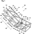
- Fig. 1 shows a representation of a supporting structure 100 according to an exemplary embodiment.
- the supporting structure 100 is a truss consisting of upper chords 102, lower chords 104, struts 106 and uprights 108, and cross struts 110.
- the upper chords 102 and lower chords 104 run essentially parallel to one another.
- the lower chords 104 are connected to one another by cross struts 110.
- the cross struts 110 are arranged perpendicular to the lower chords 104.
- the struts 106 are arranged diagonally to the upper chords 102 and lower chords 104 and each connect one of the upper chords 102 to one of the lower chords 104.
- the uprights 108 are arranged perpendicular to the upper chords 102 and lower chords 104 and each connect one of the upper chords 102 to one of the lower chords 104.
- the uprights 108 are connected by further cross struts 110.
- the supporting structure 100 has two end regions 112 and a central region 114.
- half of a supporting structure 100 of an escalator 116 is shown. Its central region 114 is aligned obliquely to the end regions 112 in order to overcome a height difference between the two levels connected by the escalator 116.
- the end regions 112 are aligned horizontally.
- the supporting structure 100 has a kink.
- the central region 114 can be arranged.
- stop devices 118 for personal protective equipment 130 (this is shown in the Figure 1 (shown only schematically and without an installer) are firmly connected to the supporting structure 100.
- the anchor devices 118 are dimensioned and designed in such a way that they meet the relevant standards and regulations with regard to their strength.
- the anchor devices 118 are clearly color-coded.
- the anchor devices 118 each have an eyelet 120 for at least one connecting means 123 of the personal protective equipment 130.
- the anchor devices 118 remain on the supporting structure 100 even after the completion of the escalator 116.
- the anchor devices 118 are arranged at a maximum safety distance of 122 from each other.
- the safety distance 122 is smaller than the average arm span of an average person.
- the average arm span can be specified in relevant standards and regulations.
- the anchor devices 118 are welded to the supporting structure 100. This integral connection allows the forces generated in the event of a fall to be safely transmitted into the supporting structure 100. The welding also prevents the anchor devices 118 from being accidentally unscrewed.
- the anchor devices 118 are arranged on both sides of the supporting structure 100.
- the anchor devices 118 are arranged to the right and left of the supporting structure 100. This allows the installer to secure himself on both sides simultaneously. The fall height can be reduced in this way, since the first lanyard to be tightened always slows the fall.
- the stop devices 118 are arranged in pairs opposite one another. This allows the technician to always reach at least three of the stop devices 118 simultaneously. If two technicians are working on the escalator 116 at the same time, they can easily pass each other, since one of the technicians on each side can be secured while passing. Once the technicians have passed each other, they can secure themselves again on both sides.
- the anchor devices 118 are arranged on the upper chords 102.
- the anchor devices 118 on the upper chords 102 are easily accessible to the technician because they are located at chest height while the technician is standing. By securing the upper chord 102, the fall height can be reduced.
- the upper chords 102 are sufficiently dimensioned to absorb any resulting fall energy.
- Fig. 2 shows a representation of a stop device 118 on a supporting structure 100 according to an embodiment.
- the stop device 118 corresponds in Essentially the Fig. 1 shown stop devices.
- the escalator 116 is already partially assembled.
- a balustrade 200 is attached to the upper chord 102 using balustrade clamps 202.
- the balustrade 200 provides lateral fall protection.
- the balustrade clamp 202 is screwed to the upper chord 102 and securely clamps the balustrade 200 between its clamping jaws.
- the stop device 118 is arranged between a lower edge of the balustrade 200 and the upper chord 102.
- the anchor devices 300 are arranged on an underside of the upper chord 102.
- the anchor device 302 can be anchored from below or diagonally below in the anchor device 300 and can be removed from the anchor device 300 again after use. from below, lateral shear loads on the anchor devices 302 can be avoided in the event of a fall.
- the shaft 310 is pushed further into the hole 308, the pawl 306, which is thus relieved of load, is realigned longitudinally by an integrated mechanism and pulled out of the hole 308 together with the shaft 310.
- the thread 314 is designed as a blind hole and is arranged in a stiffening region 124 of the anchor device 300 in order to avoid any notch effects in the supporting structure 100.
- the stiffening region 124 is in particular provided with welded to the supporting structure 100 and has a greater thickness than the depth of the blind hole.
- This system makes it possible to hook into the next anchorage device 118 while wearing personal protective equipment 130 without having to unhook from the current anchorage device 118. This makes it possible to secure oneself from one anchorage device 118 to the next along the escalator 116. This ensures compliance with the defined safety concept for the installers, which stipulates that they may only enter the unfinished escalator 116 or the unfinished moving walkway while secured against falls.
- the stop devices 118 are preferably welded to the upper chord 102 of the truss 100, or to other escalator structural elements, for example, soldered or glued, provided that these elements withstand the test forces required by the standards.
- the illustrated design enables several people to secure themselves on the escalator 116 at the same time with their personal protective equipment 130 without any additional effort.
- the anchor devices 118 are highlighted by color or other markings to prevent accidental securing to components not intended for this purpose.
- anchor devices 118 are pre-assembled at the factory and can therefore be used immediately for fall protection without the need for complex assembly work prior to installation of the escalator 116.
- the anchor devices 118 can be used immediately for fall protection if no anchor devices are provided by the building.
- the stop devices 118 can be used both for the balustrade construction and for all subsequent repairs or modernizations of the systems, since the stop devices 118 remain installed on the escalator 116.
- the stop devices 118 themselves can be manufactured, for example, by laser cutting, flame cutting, or waterjet cutting. Likewise, the stop devices 118 can be manufactured as a gravity-cast component or using another manufacturing process.
- the illustrated anchoring devices 118 are designed for connection by welding to the upper chord 102 in such a way that they can be used for all product types.
- the size and shape of the opening for hanging the personal protective equipment 130 can vary to accommodate one or more snap or screw carabiners.
- the permanently installed stop devices 118 described in this document allow for easy handling and can be used on all escalator types. They are permanently installed on their supporting structure 100, can also be used for repairs or modernizations, and are cost-effective to manufacture.
- the use of the permanently installed stop devices 118 presented here can improve occupational safety and increase work efficiency.
Landscapes
- Health & Medical Sciences (AREA)
- General Health & Medical Sciences (AREA)
- Business, Economics & Management (AREA)
- Emergency Management (AREA)
- Escalators And Moving Walkways (AREA)
Description
Die vorliegende Erfindung betrifft ein Tragwerk einer Fahrtreppe oder eines Fahrsteigs.The present invention relates to a supporting structure of an escalator or a moving walkway.
Eine Fahrtreppe oder ein Fahrsteig ist eine Personentransportanlage mit beweglichen Oberflächensegmenten, die zu einer endlosen Kette verbunden sind und von einem Antrieb entlang einer Führung umlaufend bewegt werden können, um Personen zu transportieren. Die Oberflächensegmente sind zumindest auf einer Oberseite der Personentransportanlage nahezu lückenlos hintereinander angeordnet. Die Personentransportanlage weist zwei Endbereiche und einen Mittenbereich auf. Zumindest an den Endbereichen ist die Personentransportanlage mit einem Bauwerk verbunden. An den Endbereichen erscheinen und verschwinden die Oberflächensegmente unter einer Kammplatte und einer daran anschließenden Bodenabdeckung. Die Endbereiche sind in der Regel horizontal ausgerichtet.An escalator or moving walkway is a passenger transport system with movable surface segments that are connected to form an endless chain and can be moved by a drive along a guide to transport people. The surface segments are arranged almost seamlessly one behind the other, at least on the upper side of the passenger transport system. The passenger transport system has two end sections and a middle section. At least at the end sections, the passenger transport system is connected to a structure. At the end sections, the surface segments appear and disappear under a comb plate and an adjoining floor covering. The end sections are usually aligned horizontally.
Bei der Fahrtreppe sind die Endbereiche auf unterschiedlichen Ebenen des Bauwerks angeordnet. Bei der Fahrtreppe verläuft der Mittenbereich unter einem Winkel schräg zur Horizontalen und verbindet die Ebenen. Im Mittenbereich bilden die Oberflächensegmente der Fahrtreppe Stufen aus. Die Fahrtreppe kann als Rolltreppe bezeichnet werden.In an escalator, the end sections are arranged at different levels of the structure. The central section runs at an angle to the horizontal and connects the levels. In the central section, the surface segments of the escalator form steps. The escalator can be referred to as an escalator.
Bei dem Fahrsteig können die Endbereiche höhengleich oder auf unterschiedlichen Ebenen angeordnet sein. Dementsprechend kann der Mittenteil des Fahrsteigs horizontal oder gegenüber der Horizontalen schräg ausgerichtet sein. Der Mittenbereich des Fahrsteigs in der Regel weniger steil als der Mittenbereich der Fahrtreppe. Bei dem Fahrsteig bilden die Oberflächensegmente keine Stufen aus.In a moving walk, the end sections can be arranged at the same height or at different levels. Accordingly, the central section of the moving walk can be horizontal or inclined relative to the horizontal. The central section of the moving walk is generally less steep than the central section of the escalator. In a moving walk, the surface segments do not form steps.
Sowohl die Fahrtreppe als auch der Fahrsteig weisen ein Tragwerk auf. Das Tragwerk kann als Fachwerk ausgeführt sein. Die einzelnen Komponenten der Personentransportanlage, wie die Führung, der Antrieb, Balustraden, Handläufe und Verkleidungen werden mit dem Tragwerk verbunden. Das Tragwerk wird in der Regel vorgefertigt und in das Bauwerk eingehoben. Wenn die Endbereiche des Tragwerks mit dem Bauwerk verbunden sind, werden weitere Komponenten montiert und die Personentransportanlage betriebsbereit fertiggestellt. Insbesondere werden oft Balustraden erst montiert, nachdem das Tragwerk im Bauwerk verankert wurde.Both the escalator and the moving walkway have a supporting structure. The supporting structure can be designed as a truss. The individual components of the passenger transport system, such as the guide, the drive, balustrades, handrails and Cladding is connected to the supporting structure. The supporting structure is usually prefabricated and lifted into the building. Once the end sections of the supporting structure are connected to the structure, additional components are installed and the passenger transport system is completed and ready for operation. In particular, balustrades are often installed only after the supporting structure has been anchored in the structure.
Zum Montieren der Komponenten müssen Monteure das Tragwerk betreten. Da der Mittenbereich der Personentransportanlage oft frei durch die Luft verläuft, benötigen die Monteure eine Absturzsicherung. Die Monteure können sich beispielsweise mit großen Haken oder Karabinern direkt im Tragwerk oder an Strukturen in dem Bauwerk sichern. Alternativ oder ergänzend können temporäre Wartungsgeländer am Tragwerk mit speziellen Klemmvorrichtungen festgeklemmt werden. Die Monteure können die temporären Wartungsgeländer auch zum Einhängen ihrer persönlichen Schutzausrüstung verwenden. Die persönliche Schutzausrüstung umfasst üblicherweise ein am Körper getragenes Gurtzeug und ein daran befestigtes, längeres Seilstück, dessen Ende beispielsweise mit einem Karabinerhaken sicher, schnell und einfach an geeigneter Stelle eingehängt werden kann. Die temporäre Wartungsgeländer können nach und nach entfernt werden, wenn die Balustraden montiert werden.To assemble the components, fitters must access the supporting structure. Since the central section of the personnel transport system often runs freely through the air, the fitters require fall protection. The fitters can secure themselves, for example, with large hooks or carabiners directly in the supporting structure or to structures in the building. Alternatively or additionally, temporary maintenance railings can be clamped to the supporting structure with special clamping devices. The fitters can also use the temporary maintenance railings to attach their personal protective equipment. The personal protective equipment usually consists of a harness worn on the body and a longer piece of rope attached to it, the end of which can be hooked safely, quickly and easily to a suitable location using a snap hook, for example. The temporary maintenance railings can be gradually removed as the balustrades are installed.
Ein Sichern der persönlichen Schutzausrüstung an nicht speziell hierfür vorgesehenen Strukturen in dem Bauwerk oder an nicht speziell hierfür vorgesehenen Strukturen an dem Tragwerk kann einerseits aufwändig sein und kann andererseits ein Risiko einer nicht situationsgerechten Absturzsicherung mit sich bringen. Ein Anbringen und anschließendes Entfernen temporärer Wartungsgeländer kann zusätzlichen Aufwand erfordern. Da die temporären Wartungsgeländer beim Montieren beziehungsweise Demontieren lose Teile sind, können sie fallen gelassen werden. Die Teile des temporären Wartungsgeländers können beim Fallenlassen beträchtliche Schäden verursachen. Zusätzlich werden für unterschiedliche Typen von Tragwerken Klemmvorrichtungen mit unterschiedlichen Klemmquerschnitten beziehungsweise Klemmflächen benötigt, um einen flächigen Kontakt zum jeweiligen Tragwerk sicherzustellen.Securing personal protective equipment to structures in the building that are not specifically designed for this purpose, or to structures on the supporting structure that are not specifically designed for this purpose, can be complex and can also pose a risk of inappropriate fall protection. Installing and then removing temporary maintenance railings can require additional effort. Since temporary maintenance railings are loose parts during installation or removal, they can be dropped. Parts of the temporary maintenance railing can cause considerable damage if dropped. In addition, clamping devices with different clamping cross-sections or clamping surfaces are required for different types of supporting structures to ensure flat contact with the respective supporting structure.
Es kann unter anderem ein Bedarf an einem verbesserten Arbeitsschutz bei der Arbeit an einer Fahrtreppe oder an einem Fahrsteig bestehen. Insbesondere kann ein Bedarf an einem Arbeitsschutz bestehen, mithilfe dessen eine Sicherheit insbesondere für Monteure während einer Installation in einer konstruktiv einfach zu realisierenden Weise, kostengünstig und/oder zuverlässig verbessert werden kann.Among other things, there may be a need for improved occupational safety when working on an escalator or moving walkway. In particular, there may be a need for occupational safety that can improve safety, particularly for fitters, during installation in a structurally simple, cost-effective, and/or reliable manner.
Einem solchen Bedarf kann dadurch entsprochen werden, dass gemäß einem Aspekt der Erfindung ein Tragwerk einer Fahrtreppe oder eines Fahrsteigs vorgeschlagen wird, wobei an einem Mittenbereich des Tragwerks zumindest zwei, maximal um einen Sicherungsabstand voneinander beabstandete, fest mit dem Tragwerk verbundene Anschlagvorrichtungen für eine persönliche Schutzausrüstung angeordnet sind. Anschlagvorrichtungen, auch als Anschlagpunkte bezeichnet, sind hierbei speziell geschaffene Stellen, an denen die persönliche Schutzausrüstung sicher, schnell und einfach eingehängt werden kann. Die Anschlagvorrichtungen weisen üblicherweise eine Struktur auf, an der eine Öse ausgebildet ist, so dass die persönliche Schutzausrüstung schnell und sicher daran befestigt, aber auch wieder rasch gelöst werden kann.Such a need can be met by proposing, according to one aspect of the invention, a supporting structure for an escalator or moving walkway, wherein at least two anchoring devices for personal protective equipment are arranged in a central region of the supporting structure, spaced apart from one another by a maximum safety distance and firmly connected to the supporting structure. Anchoring devices, also referred to as anchor points, are specially created locations to which personal protective equipment can be securely, quickly, and easily attached. The anchoring devices typically have a structure with an eyelet formed thereon, so that the personal protective equipment can be quickly and securely attached to it, but also quickly detached again.
Vorteilhafte Ausführungsformen sind in den abhängigen Ansprüchen definiert und in der Beschreibung beschrieben.Advantageous embodiments are defined in the dependent claims and described in the description.
Ein Tragwerk kann ein Strukturbauteil einer Personentransportanlage in Form einer Fahrtreppe oder eines Fahrsteigs sein. Das Tragwerk kann ein Fachwerkträger sein. Das Tragwerk kann als Tragwerkbestandteile Obergurte, Untergurte, Streben, Steher und Querstreben aufweisen. Die Obergurte und Untergurte können im Wesentlichen parallel zueinander angeordnet sein und in einer Haupterstreckungsrichtung des Tragwerks verlaufen. Die Obergurte und Untergurte können durch diagonal zu den Obergurten und Untergurten ausgerichtete Streben und/oder quer zu den Obergurten und Untergurten ausgerichtete Steher miteinander verbunden sein. Obergurte, Untergurte, Streben, Steher und Querstreben können Metallprofile sein. Insbesondere können die Obergurte, Untergurte, Streben, Steher und Querstreben L-Profile aus Metall sein. Die Obergurte, Untergurte, Streben, Steher und Querstreben können über Knotenbleche miteinander verbunden sein. Beispielsweise können die Obergurte, Untergurte, Streben, Steher und Querstreben verschweißt, verschraubt, verstiftet und/oder vernietet sein.A supporting structure can be a structural component of a passenger transport system in the form of an escalator or a moving walkway. The supporting structure can be a truss girder. The supporting structure can have upper chords, lower chords, struts, uprights, and cross braces as structural components. The upper chords and lower chords can be arranged essentially parallel to one another and run in a main extension direction of the supporting structure. The upper chords and lower chords can be connected to one another by struts aligned diagonally to the upper chords and lower chords and/or by uprights aligned transversely to the upper chords and lower chords. Upper chords, lower chords, struts, uprights, and cross braces can be metal profiles. In particular, the upper chords, lower chords, struts, uprights, and cross braces can be L-profiles made of metal. The upper chords, lower chords, struts, uprights, and cross braces can be connected to one another via gusset plates. For example, the top chords, bottom chords, struts, uprights, and cross braces can be welded, bolted, pinned, and/or riveted.
Ein Mittenbereich des Tragwerks kann zwischen zwei Endbereichen des Tragwerks angeordnet sein. Der Mittenbereich ist bei einer Fahrtreppe in einer Einbaulage des Tragwerks schräg zur Horizontalen ausgerichtet. Bei einem Fahrsteig kann der Mittenbereich horizontal verlaufen oder schräg nach oben oder unten verlaufen. Die Endbereiche können sowohl bei einer Fahrtreppe als auch bei einem Fahrsteig im Allgemeinen horizontal ausgerichtet sein. Das Tragwerk kann an den Endbereichen Verbindungsstellen zu einem Bauwerk aufweisen. Ebenso können an den Endbereichen Hebestellen zum Anheben des Tragwerks angeordnet sein.A central section of the supporting structure can be located between two end sections of the supporting structure. In an escalator, the central section is aligned diagonally to the horizontal in one installed position of the supporting structure. In a moving walk, the central section can run horizontally or diagonally upwards or downwards. The end sections of both an escalator and a moving walk can generally be aligned horizontally. The supporting structure can have connection points to a building at the end sections. Lifting points for raising the supporting structure can also be arranged at the end sections.
Eine Anschlagvorrichtung für persönliche Schutzausrüstung ist gemäß geltenden Normen und Vorschriften speziell für diesen Einsatzzweck dimensioniert. Die Anschlagvorrichtung kann beispielsweise der Europäischen Norm EN 365 und/oder EN 795 entsprechen. Die Anschlagvorrichtung für persönliche Schutzausrüstung ist eine extra dazu ausgelegte Fixvorrichtung, die speziell zum Zweck der Absturzsicherung mittels persönlicher Schutzausrüstung am Tragwerk vorgesehen ist. Die Anschlagvorrichtung für persönliche Schutzausrüstung ist keine Montagestelle für Komponenten der Fahrtreppe beziehungsweise des Fahrsteigs. Sie dient auch nicht zum Ansetzen von Hebezeugen, wie beispielsweise die vorangehend beschriebenen Hebestellen. Die Anschlagvorrichtung ist so dimensioniert, dass sie die auftretenden Kräfte eines Normsturzes ohne Beschädigung aufnehmen und in das Tragwerk ableiten kann. Beispielsweise kann die Anschlagvorrichtung für eine Belastung mit 16 Kilonewton ausgelegt sein. Die Anschlagvorrichtung kann auch für größere Kräfte dimensioniert sein. Die hier vorgestellten Anschlagvorrichtungen verbleiben auch nach der Montage der Komponenten der Personentransportanlage am Tragwerk.An anchor device for personal protective equipment is specifically dimensioned for this purpose in accordance with applicable standards and regulations. The anchor device can, for example, comply with the European standard EN 365 and/or EN 795. The anchor device for personal protective equipment is a specially designed fixed device that is specifically intended for the purpose of fall protection using personal protective equipment on the supporting structure. The anchor device for personal protective equipment is not an installation point for components of the escalator or moving walkway. It is also not used for attaching lifting equipment, such as the lifting points described above. The anchor device is dimensioned such that it can absorb the forces occurring during a standard fall without damage and transfer them to the supporting structure. For example, the anchor device can be designed for a load of 16 kilonewtons. The anchor device can also be dimensioned for greater forces. The anchor devices presented here remain on the supporting structure even after the components of the passenger transport system have been installed.
Die Anschlagvorrichtung weist eine Öse auf. Die Öse kann ein Durchbruch, eine Öffnung oder ein Loch sein, in das zumindest ein Verbindungsmittel der persönlichen Schutzausrüstung eingehängt werden kann. Die Öse kann auch so groß dimensioniert sein, dass zwei Verbindungsmittel von unterschiedlichen Personen gleichzeitig eingehängt werden können. Die Öse kann regelmäßig oder unregelmäßig geformt sein.The anchor device has an eyelet. The eyelet can be a through-hole, an opening, or a hole into which at least one lanyard of the personal protective equipment can be hooked. The eyelet can also be large enough to allow two lanyards to be hooked in by different people simultaneously. The eyelet can be regular or irregular in shape.
Die Anschlagvorrichtung kann durch eine Signalfarbe beziehungsweise Kontrastfarbe zu einer Grundfarbe des Tragwerks farblich hervorgehoben sein, damit sie durch das zu sichernde Montagepersonal rasch und unzweifelhaft identifiziert werden kann. Das Einhängen an einer ungeeigneten Stelle des Tragwerks kann so vermieden werden. Durch die fest am Tragwerk vorgehaltenen Anschlagvorrichtungen kann sich ein Monteur beim Betreten des Tragwerks sofort gegen Absturz sichern, ohne zuerst eine dafür geeignete Stelle am Tragwerk oder Bauwerk zu suchen oder zuerst ein temporäres Wartungsgeländer zu errichten.The anchorage device can be highlighted in a signal color or a color that contrasts with the base color of the supporting structure, so that it can be quickly and easily identified by the installation personnel being secured. This prevents the anchorage from being suspended at an inappropriate location on the supporting structure. With anchorage devices permanently attached to the supporting structure, a technician can immediately protect themselves against falls when entering the supporting structure without first having to search for a suitable location on the supporting structure or building or first erect a temporary maintenance railing.
Wie bereits angedeutet, weist die persönliche Schutzausrüstung, kurz PSA, beispielsweise einen Auffanggurt (Gurtzeug) und ein Höhensicherungsgerät mit zwei separaten Verbindungsmitteln und zumindest ein energieabsorbierendes Element auf. Die Verbindungsmittel können beispielsweise ein- und ausziehbar sein. Das energieabsorbierende Element kann die kinetische Energie eines fallenden Körpers teilweise absorbieren und so Verletzungen verhindern.As already mentioned, personal protective equipment, or PPE for short, includes, for example, a full body harness and a fall arrester with two separate lanyards and at least one energy-absorbing element. The lanyards can be retractable and extendable, for example. The energy-absorbing element can partially absorb the kinetic energy of a falling body, thus preventing injuries.
Ein Sicherungsabstand zwischen zwei benachbarten Anschlagvorrichtungen kann durch die geltenden Normen und Vorschriften vorgegeben sein. Der Sicherungsabstand sollte im Allgemeinen kleiner als eine durchschnittliche Armspanne eines durchschnittlichen Menschen sein. Der Sicherungsabstand kann beispielsweise in einem Bereich von 0,5m bis 3m, vorzugsweise 1m bis 2m, liegen und kann z.B. 1,2 Meter betragen. Durch die Anordnung von um maximal den Sicherungsabstand voneinander beabstandeten Anschlagvorrichtungen kann jeder Monteur immer zumindest zwei Anschlagvorrichtungen gleichzeitig erreichen. Die Anschlagvorrichtungen können entlang der gesamten Länge des Tragwerks, insbesondere entlang der gesamten Länge des Mittenbereichs des Tragwerks in vorzugsweise gleichmäßigen Abständen angeordnet sein.A safety distance between two adjacent anchor devices may be specified by applicable standards and regulations. The safety distance should generally be smaller than the average arm span of an average person. The safety distance can, for example, be in a range of 0.5 m to 3 m, preferably 1 m to 2 m, and can be, for example, 1.2 meters. By arranging anchor devices spaced at a maximum of the safety distance from each other, each installer can always reach at least two anchor devices simultaneously. The anchor devices can be arranged along the entire length of the supporting structure, in particular along the entire length of the central region of the supporting structure, preferably at equal intervals.
Die Anschlagvorrichtungen können auf gegenüberliegenden Seiten des Tragwerks angeordnet sein. Die Anschlagvorrichtungen können gleichmäßig rechts und links des Tragwerks verteilt angeordnet sein. Der Monteur kann sich so immer in jeweils einer rechten Anschlagvorrichtung und einer linken Anschlagvorrichtung einhängen. Wenn der Monteur dann abstürzen sollte, wird sein Sturz immer von dem weiter entfernt eingehängten Verbindungsmittel gehalten. So kann eine Sturzhöhe reduziert werden.The anchor devices can be arranged on opposite sides of the structure. The anchor devices can be evenly distributed to the right and left of the structure. This allows the installer to always connect to a right anchor device and a left anchor device. If the installer then falls, their fall will always be stopped by the lanyard attached further away. This can reduce the fall height.
Dadurch wird auch eine zu absorbierende Sturzenergie beziehungsweise kinetische Energie reduziert. Weiterhin wird die Gefahr eines Bodensturzes beziehungsweise Aufpralls am Boden reduziert.This also reduces the amount of fall energy or kinetic energy that needs to be absorbed. Furthermore, the risk of falling or hitting the ground is reduced.
An zumindest einem Endbereich des Tragwerks kann zumindest eine fest mit dem Tragwerk verbundene, farblich gekennzeichnete Ankervorrichtung für eine Anschlageinrichtung für die persönliche Schutzausrüstung angeordnet sein. Die Ankervorrichtung kann maximal um den Sicherungsabstand von einer benachbarten Anschlagvorrichtung beabstandet sein. Eine Anschlagvorrichtung benötigt durch ihre Ausprägung einer Öse Bauraum. Insbesondere in den Endbereichen ist der verfügbare Raum begrenzt. Eine Ankervorrichtung kann wesentlich weniger Bauraum benötigen als eine Anschlagvorrichtung. Wie die Anschlagvorrichtung ist die Ankervorrichtung gemäß geltenden Normen und Vorschriften dimensioniert. Die Ankervorrichtung ist eine extra dazu ausgelegte Fixierstelle, die nur zum Zweck der Absturzsicherung mittels einer Anschlageinrichtung vorgesehen ist. Die Ankervorrichtung ist keine Montagevorrichtung für Komponenten der Fahrtreppe beziehungsweise des Fahrsteigs. Die Ankervorrichtung ist so dimensioniert, dass sie die auftretenden Kräfte eines Normsturzes ohne Beschädigung aufnehmen und in das Tragwerk ableiten kann. Die Ankervorrichtung kann überdimensioniert sein. Die Ankervorrichtung kann das Tragwerk lokal versteifen. Im Bereich der Ankervorrichtung kann ein Bauteil des Tragwerkes verstärkt sein. Die Ankervorrichtung verbleibt auch nach der Montage der Komponenten der Personentransportanlage am Tragwerk. Der Monteur kann zumindest eine standardisierte Anschlageinrichtung mit sich führen. Beim Betreten des Endbereichs kann der Monteur die Ankervorrichtung sofort erkennen und seine mitgeführte Anschlageinrichtung mit der Ankervorrichtung verbinden. An der Anschlageinrichtung kann der Monteur dann seine persönliche Schutzausrüstung einhängen, da an dieser beispielsweise eine Öse ausgebildet ist. Somit bilden die Ankervorrichtung und die Anschlageinrichtung zusammen eine Anschlagvorrichtung.At least one color-coded anchor device for an anchorage device for personal protective equipment can be arranged at at least one end area of the supporting structure. The anchor device can be spaced from an adjacent anchor device by a maximum of the safety distance. Due to its eyelet design, an anchor device requires installation space. Available space is particularly limited in the end areas. An anchor device can require significantly less installation space than a stop device. Like the stop device, the anchor device is dimensioned in accordance with applicable standards and regulations. The anchor device is a specially designed fixing point intended solely for the purpose of fall protection using an anchor device. The anchor device is not an assembly device for components of the escalator or moving walkway. The anchor device is dimensioned such that it can absorb the forces occurring during a standard fall without damage and transfer them to the supporting structure. The anchor device can be oversized. The anchor device can locally stiffen the supporting structure. A component of the supporting structure can be reinforced in the area of the anchor device. The anchor device remains attached to the supporting structure even after the components of the passenger transport system have been installed. The installer can carry at least one standardized anchor device. Upon entering the end area, the installer can immediately recognize the anchor device and connect the anchor device they are carrying to the anchor device. The installer can then attach their personal protective equipment to the anchor device, as it has an eyelet, for example. Thus, the anchor device and the anchor device together form a single anchor device.
In dem Endbereich können zumindest zwei Ankervorrichtungen auf gegenüberliegenden Seiten des Tragwerks angeordnet sein. Die Ankervorrichtungen können gleichmäßig rechts und links des Tragwerks verteilt angeordnet sein. Der Monteur kann so immer jeweils eine Anschlageinrichtung mit einer rechten Ankervorrichtung und einer linken Ankervorrichtung verbinden. Wenn der Monteur dann abstürzen sollte, wird sein Sturz immer von dem weiter entfernt eingehängten Verbindungsmittel gehalten. So kann die Sturzhöhe reduziert werden. Dadurch wird auch die zu absorbierende Sturzenergie reduziert. Weiterhin wird die Gefahr des Bodensturzes reduziert.At least two anchor devices can be arranged on opposite sides of the structure in the end area. The anchor devices can be evenly distributed to the right and left of the structure. This allows the fitter to always connect one anchor device to a right anchor device and one to a left anchor device. If the fitter then falls, his fall will be always held by the lanyard attached further away. This can reduce the fall height. This also reduces the fall energy that needs to be absorbed. Furthermore, the risk of falling to the ground is reduced.
Die Anschlagvorrichtungen und/oder die Ankervorrichtungen können paarweise gegenüberliegend angeordnet sein. Durch auf gleicher Höhe paarweise angeordnete Anschlagvorrichtungen und/oder Ankervorrichtungen kann der Monteur immer zumindest drei Anschlagvorrichtungen und/oder Ankervorrichtungen erreichen. Wenn zwei Monteure zusammen an der gleichen Personentransportanlage arbeiten, können sie durch paarweise angeordnete Anschlagvorrichtungen und/oder Ankervorrichtungen einfach aneinander vorbeiklettern, ohne die persönliche Schutzausrüstung aushängen zu müssen.The anchor devices and/or the anchoring devices can be arranged in pairs, opposite each other. By arranging the anchor devices and/or the anchoring devices in pairs at the same height, the technician can always reach at least three anchor devices and/or the anchoring devices. If two technicians are working together on the same personnel transport system, the anchor devices and/or the anchoring devices arranged in pairs allow them to easily climb past each other without having to remove their personal protective equipment.
Die Anschlagvorrichtungen und/oder Ankervorrichtungen können stoffschlüssig mit dem Tragwerk verbunden sein. Die Anschlagvorrichtungen und/oder Ankervorrichtungen können mit dem Tragwerk verschweißt sein. Durch verschweißte Anschlagvorrichtungen und/oder Ankervorrichtungen können die Anschlagvorrichtungen und/oder Ankervorrichtungen nicht aus Versehen entfernt werden. Alternativ können die Anschlagvorrichtungen und/oder Ankervorrichtungen auch verlötet oder verklebt sein.The anchor devices and/or anchoring devices can be integrally bonded to the supporting structure. The anchor devices and/or anchoring devices can be welded to the supporting structure. Welded anchor devices and/or anchoring devices prevent the anchor devices and/or anchoring devices from being accidentally removed. Alternatively, the anchor devices and/or anchoring devices can also be soldered or glued.
Die Anschlagvorrichtungen und/oder Ankervorrichtungen können an zumindest einem der Obergurte des Tragwerks angeordnet sein. Durch eine Anordnung am Obergurt können die Anschlagvorrichtungen und/oder Ankervorrichtungen für den Monteur gut sichtbar und leicht erreichbar sein. Wenn der Monteur im Tragwerk steht, kann sich der Obergurt ungefähr auf Brusthöhe befinden. Die Verbindungsmittel sind lang genug, um auch Arbeiten am Untergurt zuzulassen. Durch die Anordnung der Anschlagvorrichtungen und/oder Ankervorrichtungen am Obergurt wird ein Sturz früher aufgefangen und die Sturzhöhe reduziert. Dadurch wird auch die zu absorbierende Sturzenergie reduziert. Weiterhin wird die Gefahr des Bodensturzes reduziert.The anchor devices and/or anchoring devices can be arranged on at least one of the upper chords of the supporting structure. By arranging them on the upper chord, the anchor devices and/or anchoring devices can be clearly visible and easily accessible for the fitter. When the fitter is standing in the supporting structure, the upper chord can be approximately at chest height. The connecting devices are long enough to also allow work on the lower chord. By arranging the anchor devices and/or anchoring devices on the upper chord, a fall is arrested earlier and the fall distance is reduced. This also reduces the fall energy that needs to be absorbed. Furthermore, the risk of falling to the ground is reduced.
Das Tragwerk kann mit den Obergurten und den Untergurten einen Innenraum des Tragwerks umschließen. Die Anschlagvorrichtungen können zu einem Innenraum des Tragwerks hin ausgerichtet sein. Die Anschlagvorrichtungen können in Richtung des Innenraums ausgerichtet sein. Damit sind die Anschlagvorrichtungen aus dem Innenraum heraus gut erreichbar. Zum Einhängen eines Verbindungsmittels muss nicht auf eine Außenseite des Tragwerks gegriffen werden.The structure can enclose an interior space of the structure with the upper and lower chords. The anchoring devices can be directed towards an interior space of the structure. The anchoring devices can be directed towards the interior space. This means that the anchoring devices are outside the interior space. Easily accessible from the outside. There is no need to reach onto the outside of the supporting structure to attach a connecting device.
Die Anschlagvorrichtungen können aus einem Plattenmaterial geschnitten sein. Die Anschlagvorrichtungen können je einen Versteifungsbereich zum lokalen Versteifen des Tragwerks sowie eine Lasche mit einer Öse aufweisen. Ein Plattenmaterial kann ein dickes Metallblech sein. Das Plattenmaterial kann beispielsweise Stahlblech sein. Die Anschlagvorrichtungen können beispielsweise aus dem Plattenmaterial gebrannt, gestanzt, gelasert, wasserstrahlgeschnitten oder gefräst werden. Ein Versteifungsbereich kann zumindest bereichsweise ein Profil des Tragwerkbestandteils abbilden, an dem die Anschlagvorrichtung angeordnet ist. Der Versteifungsbereich kann mit dem Tragwerkbestandteil verschweißt sein. Der Versteifungsbereich kann eine Krafteinleitungsfläche des Tragwerkbestandteils zum Einleiten der Sturzenergie vergrößern, sodass das Tragwerk bei einem Sturz eines Monteurs nicht geschädigt wird. Dadurch kann das Tragwerk außerhalb der Anschlagvorrichtungen geringer dimensioniert werden, da der Versteifungsbereich den Tragwerksbestandteil an der Krafteinleitungsfläche versteift. Der Versteifungsbereich kann beispielsweise zwei V-förmig angeordnete Schenkel aufweisen, so dass die Anschlagvorrichtung einem Schmetterling mit ausgebreiteten Flügeln gleicht. Die Schenkel können die Krafteinleitungsfläche entlang einer Erstreckungsrichtung des Tragwerkbestandteils vergrößern. Eine Lasche kann von dem Versteifungsbereich abstehen. Die Lasche kann über den Tragwerksbestandteil überstehen. Die Lasche kann mittig zwischen den Schenkeln angeordnet sein. Die Lasche kann zungenförmig ausgeführt sein. Ein Ende der Lasche kann abgerundet sein. Die Öse kann ein Durchbruch durch die Lasche sein. Die Öse kann beispielsweise kreisförmig oder oval sein. Ebenso kann die Öse dreieckig mit abgerundeten Ecken sein. Die Öse kann groß genug dimensioniert sein, um gleichzeitig zwei Verbindungsmittel einhängen zu können. Die Lasche und/oder die Schenkel können sich bei einem Sturz verbiegen und so Sturzenergie absorbieren. Dadurch kann der Tragwerksbestandteil vor einer Überlastung geschützt werden.The anchor devices can be cut from a sheet material. Each anchor device can have a stiffening area for locally stiffening the supporting structure and a tab with an eyelet. A sheet material can be a thick metal sheet. The sheet material can be sheet steel, for example. The anchor devices can be burned, punched, lasered, waterjet cut, or milled from the sheet material, for example. A stiffening area can, at least in part, represent a profile of the structural component to which the anchor device is arranged. The stiffening area can be welded to the structural component. The stiffening area can enlarge a force introduction area of the structural component to introduce the fall energy, so that the supporting structure is not damaged if a mechanic falls. This allows the supporting structure to be dimensioned smaller outside the anchor devices, since the stiffening area stiffens the structural component at the force introduction area. The stiffening area can, for example, have two V-shaped legs, so that the anchor device resembles a butterfly with outstretched wings. The legs can enlarge the force introduction area along a direction of extension of the structural component. A tab can protrude from the stiffening area. The tab can protrude beyond the structural component. The tab can be arranged centrally between the legs. The tab can be tongue-shaped. One end of the tab can be rounded. The eyelet can be a cutout through the tab. The eyelet can be circular or oval, for example. The eyelet can also be triangular with rounded corners. The eyelet can be large enough to allow two connecting devices to be attached simultaneously. The tab and/or the legs can bend in the event of a fall and thus absorb fall energy. This can protect the structural component from overload.
Die Anschlagvorrichtungen können geschnitten und gebogen sein. Die Lasche kann in einem Winkel zu dem Versteifungsbereich ausgerichtet sein. Der Anschlagvorrichtung kann insbesondere als Stanzbiegeteil ausgeführt sein. Durch die gebogene Lasche kann das Verbindungsmittel leicht in die Öse eingehängt werden. Die Lasche kann insbesondere nach oben gebogen sein. Dadurch kann sich die Lasche bei einem Sturz um einem größeren Winkelbetrag verbiegen, als wenn die Lasche waagerecht angeordnet wäre. So kann die Lasche mehr Sturzenergie absorbieren.The anchor devices can be cut and bent. The tab can be aligned at an angle to the stiffening area. The anchor device can be designed, in particular, as a stamped and bent part. The bent tab allows the connecting device to be easily hooked into the eyelet. The tab can In particular, it should be bent upwards. This allows the tab to bend at a greater angle in a fall than if it were positioned horizontally. This allows the tab to absorb more fall energy.
An zumindest einem der in der Einbaulage horizontal ausgerichteten Endbereiche kann zumindest eine, maximal um den Sicherungsabstand von einer benachbarten Anschlagvorrichtung beabstandete, fest mit dem Tragwerk verbundene, farblich gekennzeichnete Anschlagvorrichtung angeordnet sein. Die Endbereiche des Tragwerks können über eine Kante des Bauwerks hinausragen. Dabei kann bereits an einem Übergang von dem Endbereich zu dem Mittenbereich Absturzgefahr bestehen. Durch zumindest eine Anschlagvorrichtung im Bereich des Übergangs kann sich der Monteur bereits am Übergang sichern.At least one color-coded anchor device can be arranged at at least one of the end areas, which are horizontally aligned in the installed position. It is firmly connected to the supporting structure and spaced at a maximum distance equal to the safety distance from an adjacent anchor device. The end areas of the supporting structure can extend beyond an edge of the structure. In this case, a fall hazard may already exist at the transition from the end area to the middle area. By installing at least one anchor device in the transition area, the installer can secure himself at the transition.
Die Ankervorrichtung kann ein Gewinde für eine als Schrauböse ausgebildete Anschlageinrichtung aufweisen. Die Ankervorrichtung kann einen Versteifungsbereich aufweisen, der mit dem Tragwerksbestandteil verschweißt ist. Der Versteifungsbereich kann ein Sackloch mit dem Gewinde aufweisen. Dadurch kann eine Schwächung des Tragwerksbestandteils durch das Gewinde vermieden werden. Eine als Schrauböse ausgestaltete Anschlageinrichtung kann eine geschmiedete Öse und einen Gewindestift aufweisen. Der Gewindestift kann temporär mit der Öse drehfest verbunden werden. Dadurch kann die Schrauböse werkzeuglos in die Ankervorrichtung geschraubt werden. Nach dem Einschrauben kann die drehfeste Verbindung gelöst werden, sodass die Öse sich unabhängig von dem Gewindestift drehen kann. Durch die frei drehbare Öse kann sich die Schrauböse nicht von selbst aus dem Ankervorrichtung herausdrehen. Somit bilden die Ankervorrichtung und die mit ihr verbundene Schrauböse beziehungsweise Anschlageinrichtung zusammen eine Anschlagvorrichtung.The anchor device can have a thread for an anchoring device designed as a screw eye. The anchor device can have a stiffening area that is welded to the structural component. The stiffening area can have a blind hole with the thread. This can prevent the structural component from weakening due to the thread. An anchor device designed as a screw eye can have a forged eye and a threaded pin. The threaded pin can be temporarily connected to the eye in a rotationally fixed manner. This allows the screw eye to be screwed into the anchor device without the need for tools. After screwing in, the rotationally fixed connection can be released so that the eye can rotate independently of the threaded pin. The freely rotating eye prevents the screw eye from unscrewing itself from the anchor device. The anchor device and the screw eye or anchoring device connected to it thus together form an anchoring device.
Die Ankervorrichtung kann ein Loch für eine als Sperrklinkenanker ausgebildete Anschlageinrichtung aufweisen. Das Loch kann ein Durchgangsloch sein. Das Loch kann seitlich von dem Tragwerksbestandteil in einem eigenen Bauteil angeordnet sein. Durch die seitliche Anordnung kann eine Schwächung des Tragwerksbestandteils durch das Loch vermieden werden. Ein Sperrklinkenanker kann eine bewegliche Sperrklinke, einen flexiblen Schaft und eine Öse aufweisen. Die Sperrklinke kann an einem Ende des Schafts angeordnet sein. Die Öse kann an einem entgegengesetzten Ende des Schafts angeordnet sein. Die Sperrklinke kann in einer entsperrten Position in das Loch eingeführt werden. Hinter dem Loch kann die Sperrklinke in eine gesperrte Position bewegt werden. Eine Feder am Schaft kann die Sperrklinke in der gesperrten Position halten. In der gesperrten Position kann die Sperrklinke quer zu dem Loch angeordnet sein und an einer Rückseite der Ankervorrichtung anliegen. So kann der Sperrklinkenanker nicht mehr aus der Ankervorrichtung gezogen werden. Zum Entfernen des Sperrklinkenankers kann die Feder zusammengedrückt werden und die Sperrklinke wieder in die entsperrte Position gebracht werden. Dann kann der Sperrklinkenanker wieder aus der Ankervorrichtung entfernt werden.The anchor device may have a hole for an anchoring device designed as a pawl anchor. The hole may be a through hole. The hole may be arranged laterally of the structural component in a separate component. The lateral arrangement can prevent weakening of the structural component by the hole. A pawl anchor may have a movable pawl, a flexible shaft, and an eyelet. The pawl may be arranged at one end of the shaft. The eyelet may be arranged at an opposite end of the shaft. The pawl can be inserted into the hole in an unlocked position. Behind the hole, the pawl can be moved to a locked position. A spring on the shaft can hold the pawl in the locked position. In the locked position, the pawl can be arranged transversely to the hole and rest against a rear side of the anchor device. This prevents the pawl anchor from being pulled out of the anchor device. To remove the pawl anchor, the spring can be compressed and the pawl can be moved back to the unlocked position. The pawl anchor can then be removed from the anchor device.
Die Ankervorrichtung kann an einer Unterseite eines Obergurts des Tragwerks angeordnet sein. Durch eine Anordnung an der Unterseite kann eine seitliche Belastung der Anschlageinrichtung bei einem Sturz verhindert werden.The anchor device can be located on the underside of an upper chord of the structure. Locating it on the underside can prevent lateral loading of the anchor device in the event of a fall.
Es wird darauf hingewiesen, dass einige der möglichen Merkmale und Vorteile der Erfindung hierin mit Bezug auf unterschiedliche Ausführungsformen von Verfahren einerseits und von Vorrichtungen andererseits beschrieben sind. Ein Fachmann erkennt, dass die Merkmale in geeigneter Weise kombiniert, angepasst oder ausgetauscht werden können, um zu weiteren Ausführungsformen der Erfindung zu gelangen.It should be noted that some of the possible features and advantages of the invention are described herein with reference to different embodiments of methods on the one hand and devices on the other. A person skilled in the art will recognize that the features can be combined, adapted, or exchanged as appropriate to achieve further embodiments of the invention.
Nachfolgend werden Ausführungsformen der Erfindung unter Bezugnahme auf die beigefügten Zeichnungen beschrieben, wobei weder die Zeichnungen noch die Beschreibung als die Erfindung einschränkend auszulegen sind.
-
Fig. 1 zeigt eine Darstellung eines Tragwerks gemäß einem Ausführungsbeispiel; -
Fig. 2 zeigt eine Darstellung einer Anschlagvorrichtung an einem Tragwerk gemäß einem Ausführungsbeispiel; und -
Fig. 3 zeigt eine Darstellung von Ankervorrichtungen an einem Tragwerk gemäß einem Ausführungsbeispiel.
-
Fig. 1 shows a representation of a supporting structure according to an embodiment; -
Fig. 2 shows a representation of a stop device on a supporting structure according to an embodiment; and -
Fig. 3 shows a representation of anchor devices on a supporting structure according to an embodiment.
Die Figuren sind lediglich schematisch und nicht maßstabsgetreu. Gleiche Bezugszeichen bezeichnen gleiche oder gleichwirkende Merkmale.The figures are merely schematic and not to scale. Like reference numerals denote like or equivalent features.
Das Tragwerk 100 weist zwei Endbereiche 112 und einen Mittenbereich 114 auf. Im vorliegenden Ausführungsbeispiel ist die Hälfte eines Tragwerks 100 einer Fahrtreppe 116 dargestellt. Dessen Mittenbereich 114 ist schräg zu den Endbereichen 112 ausgerichtet, um eine Höhendifferenz zwischen den zwei durch die Fahrtreppe 116 verbundenen Ebenen zu überwinden. Die Endbereiche 112 sind horizontal ausgerichtet. An Übergängen zwischen den Endbereichen 112 und dem Mittenbereich 114 weist das Tragwerk 100 jeweils einen Knick auf. Bei einem Fahrsteig kann der Mittenbereich 114 An dem Mittenbereich 114 sind Anschlagvorrichtungen 118 für persönliche Schutzausrüstungen 130 (diese ist in der
Die Anschlagvorrichtungen 118 sind maximal in einem Sicherungsabstand 122 zueinander angeordnet. Der Sicherungsabstand 122 ist kleiner als eine durchschnittliche Armspanne eines durchschnittlichen Menschen. Die durchschnittliche Armspanne kann in entsprechenden Normen und Vorschriften festgelegt sein. Durch die Abstandsbegrenzung auf weniger als den Sicherungsabstand 122 kann ein Monteur immer mindestens zwei der Anschlagvorrichtungen 118 erreichen und sich so sichern.The
Vorzugsweise sind die Anschlagvorrichtungen 118 mit dem Tragwerk 100 verschweißt. Durch die stoffschlüssige Verbindung können bei einem Sturz entstehende Sturzkräfte sicher in das Tragwerk 100 eingeleitet werden. Durch das Verschweißen können die Anschlagvorrichtungen 118 auch nicht aus Versehen abgeschraubt werden.Preferably, the
In einem Ausführungsbeispiel sind die Anschlagvorrichtungen 118 an beiden Seiten des Tragwerks 100 angeordnet. Die Anschlagvorrichtungen 118 sind rechts und links des Tragwerks 100 angeordnet. So kann sich der Monteur an beiden Seiten gleichzeitig sichern. Eine Sturzhöhe kann so reduziert werden, da immer das Verbindungsmittel den Sturz bremst, das zuerst gestrafft wird.In one embodiment, the
In einem Ausführungsbeispiel sind die Anschlagvorrichtungen 118 paarweise gegenüberliegend angeordnet. So kann der Monteur immer mindestens drei der Anschlagvorrichtungen 118 gleichzeitig erreichen. Wenn zwei Monteure gleichzeitig an der Fahrtreppe 116 arbeiten, können sie problemlos aneinander vorbei, da beim Passieren pro Seite jeweils einer der der Monteure gesichert sein kann. Wenn die Monteure aneinander vorbei sind, können sie sich wieder auf beiden Seiten sichern.In one embodiment, the
In einem Ausführungsbeispiel sind die Anschlagvorrichtungen 118 an den Obergurten 102 angeordnet. Die Anschlagvorrichtungen 118 an den Obergurten 102 sind für den Monteur gut erreichbar, da sie sich im Bereich einer Brusthöhe des stehenden Monteurs befinden. Durch die Sicherung am Obergurt 102 kann die Sturzhöhe reduziert werden. Zusätzlich sind die Obergurte 102 ausreichend dimensioniert, um eine resultierende Sturzenergie zu absorbieren.In one embodiment, the
In einem Ausführungsbeispiel sind die Anschlagvorrichtungen 118 aus einem Plattenmaterial geschnitten. Die Anschlagvorrichtungen 118 weisen je einen Versteifungsbereich 124 und eine Lasche 126 mit der Öse 120 auf. Der Versteifungsbereich 124 ist mit dem Tragwerk 100 fest verbunden und versteift das Tragwerk 100 lokal, um die Sturzenergie schadlos in das Tragwerk 100 abzuleiten. Die Lasche 126 steht von dem Versteifungsbereich 124 und dem Tragwerk 100 ab. Die Lasche 126 kann sich bei einem Sturz plastisch verformen, um einen Teil der Sturzenergie zu absorbieren.In one embodiment, the
In einem Ausführungsbeispiel weist der Versteifungsbereich 124 zwei angeordnete Schenkel 125 auf. Die Lasche 126 verbindet beide Schenkel 125 miteinander. Die Schenkel erstrecken sich von der Lasche 126 V- förmig weg und damit schräg zu einer Erstreckungsrichtung des Tragwerks 100. Die Anschlagvorrichtungen 118 sind damit näherungsweise schmetterlingsförmig ausgestaltet. An ihren Enden sind die Schenkel 125 verbreitert. An der Verbreiterung sind die Schenkel 125 näherungsweise so breit wie der Obergurt 102. Durch die schräge Ausrichtung sind die Schenkel 125 an einer zu erwartenden Kraftrichtung bei einem Sturz ausgerichtet. Die Verbreiterungen und gegebenenfalls auch die Schenkel 125 sind insbesondere auf eine Oberfläche des Obergurts 102 aufgeschweißt.In one embodiment, the
In einem Ausführungsbeispiel ragen die Laschen 126 in einen Innenraum 128 des Tragwerks 100 hinein. Dadurch sind die Ösen 120 durch den Monteur leicht erreichbar und die Verbindungsmittel 132 der persönlichen Schutzausrüstung 130 können sich durch die Schwerkraft in der Öse 120 ausrichten. Bei einem Sturz kann so eine Querbelastung des Verbindungsmittels 132 vermieden werden.In one embodiment, the
In einem Ausführungsbeispiel sind die Laschen 126 mit den Ösen 120 aus den Ebenen der Versteifungsbereiche 124 um ca. 45° nach oben herausgebogen. Damit kann das Verbindungsmittel 132 ohne Verkanten in mehrere Raumrichtungen zur Anschlagvorrichtung 118 ausgerichtet sein. Die aufgebogene Lasche 126 kann bei einem Sturz nach unten gebogen werden, um Sturzenergie abzubauen.In one embodiment, the
In einem Ausführungsbeispiel sind am Übergang von dem Endbereich 112 zum Mittenbereich 114 zwei weitere Anschlagvorrichtungen 118 angeordnet. Die Anschlagvorrichtungen sind dabei in dem Endbereich 112 angeordnet und maximal um den Sicherungsabstand 122 von den benachbarten Anschlagvorrichtungen 118 des Mittenbereichs 114 entfernt.In one embodiment, two
Unterhalb der Anschlagvorrichtung 118 verläuft ein beweglicher Handlauf 204 der Fahrtreppe 116 innerhalb des Tragwerks 100. Der Handlauf 204 wird durch Handlaufführungen 206 geführt. Die Handlaufführungen 206 sind unterhalb der Balustradenklemmen 202 montiert. Die Handlaufführungen 206 weisen Tragrollen und Führungsrollen zum seitlichen Führen des Handlaufs 204 auf. Diese Ansicht zeigt deutlich, dass die Anschlagvorrichtung 118 problemlos in der Fahrtreppe 116 verbleiben kann und nicht nach erfolgter Montage der Balustraden 200 entfernt werden muss, wie dies beispielsweise bei den eingangs erwähnten temporären Wartungsgeländern (nicht dargestellt) der Fall ist.Below the
In einem Ausführungsbeispiel sind die Ankervorrichtungen 300 an einer Unterseite des Obergurts 102 angeordnet. Dabei kann die Anschlageinrichtung 302 von unten oder schräg unten in der Ankervorrichtung 300 verankert werden und nach der Verwendung wieder nach unten aus dem Ankervorrichtung 300 entfernt werden. Durch die Montage von unten können bei einem Sturz seitliche Scherbelastungen auf die Anschlageinrichtungen 302 vermieden werden.In one embodiment, the
In einem Ausführungsbeispiel ist die Anschlageinrichtung 302 ein Sperrklinkenanker 304. Der Sperrklinkenanker 304 kann werkzeuglos an der Ankervorrichtung 400 befestigt werden. Der Sperrklinkenanker 304 weist eine Sperrklinke 306 auf, die in einer Längsrichtung des Sperrklinkenankers 304 in ein Loch 308 der Ankervorrichtung 300 eingeführt wird und sich hinter dem Loch 308 querlegt und an einer Rückseite der Ankervorrichtung 300 anliegt. Ein Schaft 310 des Sperrklinkenankers 304 ragt auf einer Vorderseite der Ankervorrichtung 300 heraus und endet in einer Öse 120. In die Öse 120 kann das Verbindungsmittel 132 der persönlichen Schutzausrüstung 130 eingehängt werden.In one embodiment, the anchor device 302 is a pawl anchor 304. The pawl anchor 304 can be attached to the anchor device 400 without tools. The pawl anchor 304 has a
Zum Entfernen des Sperrklinkenankers 304 wird der Schaft 310 weiter in das Loch 308 geschoben, die dadurch entlastete Sperrklinke 306 wird durch einen integrierten Mechanismus wieder längs ausgerichtet und zusammen mit dem Schaft 310 aus dem Loch 308 gezogen.To remove the pawl anchor 304, the
In einem Ausführungsbeispiel ist die Anschlageinrichtung 302 eine Schrauböse 312. Die Schrauböse 312 weist einen Gewindestift 316 und eine Öse 120 für das Verbindungsmittel 132 der persönlichen Schutzausrüstung 130 auf. Der Gewindestift 316 wird in ein Gewinde 314 der Ankervorrichtung 300 eingeschraubt. Das Gewinde 314 kann beispielsweise ein M16 Gewinde sein. Zum Einschrauben und Herausschrauben wird der Gewindestift 316 drehfest mit der Öse 120 verbunden. So kann die Öse 120 als Handgriff zum werkzeuglosen Einschrauben und Herausschrauben verwendet werden. Wenn der Gewindestift in das Gewinde 314 geschraubt ist, wird die drehfeste Verbindung zur Öse 120 gelöst und die Öse 120 kann sich relativ zum Gewindestift 316 frei drehen. Ein dabei verwendeter Verriegelungsmechanismus (nicht dargestellt) kann werkzeuglos bedient werden und zeigt seinen Verriegelungsstatus optisch über signalfarbige Verriegelungselemente an.In one embodiment, the anchor device 302 is a screw eye 312. The screw eye 312 has a threaded
In einem Ausführungsbeispiel ist das Gewinde 314 als Sackloch ausgeführt und ist in einem Versteifungsbereich 124 der Ankervorrichtung 300 angeordnet, um im Tragwerk 100 keine Kerbeffekte hervorzurufen. Der Versteifungsbereich 124 ist insbesondere mit dem Tragwerk 100 verschweißt und weist eine größere Dicke auf, als das Sackloch tief ist.In one embodiment, the
Nachfolgend werden mögliche Ausgestaltungen des hierin beschriebenen Tragwerks 100 bzw. der damit ausgebildeten Fahrtreppe 116 bzw. Fahrsteig nochmals mit einer teilweise anderen Wortwahl beschrieben.In the following, possible configurations of the supporting
Wird eine Fahrtreppe 116 oder ein Fahrsteig ohne Balustrade 200 geliefert, wird die Balustrade 200 nach der Einbringung vor Ort beim Kunden montiert. Hier besteht Absturzgefahr, da eine lückenlose Sicherungskette z.B. bei Fahrtreppen 116, die in einem Atrium gekreuzt übereinander installiert werden, oft schwer oder nicht realisierbar ist, da keine Anschlagvorrichtungen zur Selbstsicherung am Gebäude vorgesehen sind. Herkömmlicherweise sind auch keine Anschlagvorrichtungen an der Fahrtreppe 116 vorgesehen.If a 116 escalator or moving walk is delivered without a 200 balustrade, the 200 balustrade is installed on-site at the customer's premises after installation. This poses a risk of falling, as a continuous safety chain is often difficult or impossible to implement, for example, with 116 escalators installed crossed one above the other in an atrium, as no anchorage devices for self-protection are provided on the building. Traditionally, no anchorage devices are provided on the 116 escalator either.
Die hier vorgestellten Anschlagvorrichtungen 118 zur Sicherung von Personen mittels persönlicher Schutzausrüstung (PSA) 130 können in definierten regelmäßigen oder unregelmäßigen Abständen 122 am Fachwerkobergurt 102 angeordnet sein. Der Abstand 122 ist in
Mit diesem System ist es möglich, sich mit der persönlichen Schutzausrüstung 130 in einer nächsten Anschlagvorrichtung 118 einzuhängen, ohne sich bei der aktuellen Anschlagvorrichtung 118 aushängen zu müssen. Ein Hochsichern von einer zur nächsten Anschlagvorrichtung 118 entlang der Fahrtreppe 116 ist so möglich. Somit ist gewährleistet, dass das definierte Sicherungskonzept für die Monteure eingehalten werden kann, welches vorschreibt, dass sie nur gegen Absturz gesichert die nicht fertiggestellte Fahrtreppe 116 oder den nicht fertiggestellten Fahrsteig betreten dürfen.This system makes it possible to hook into the
Die Anschlagvorrichtungen 118 sind vorzugsweise am Obergurt 102 des Fachwerks 100, oder aber mit anderen Fahrtreppen-Strukturelementen beispielsweise verschweißt, verlötet oder verklebt, soweit diese Elemente den normativ geforderten Prüfkräften standhalten.The
Die Anschlagvorrichtung 118 ist für die dargestellte Ausführung so konstruiert, dass der Obergurt 102 der Fachwerk-Struktur verstärkt, beziehungsweise ausgesteift wird und somit eine lokale Überbelastung des Fachwerk-Obergurts 102 bei Beaufschlagen mit der Prüfkraft verhindert wird.The
Die dargestellte Ausführung ermöglicht, dass sich ohne zusätzlichen Aufwand mehrere Personen gleichzeitig auf der Fahrtreppe 116 mit ihrer persönlichen Schutzausrüstung 130 sichern können.The illustrated design enables several people to secure themselves on the
Die Anschlagvorrichtungen 118 sind durch farbliche oder andere Markierungen hervorgehoben um ein versehentliches Sichern an nicht dafür vorgesehen Bauteilen möglichst auszuschließen.The
Diese Anschlagvorrichtungen 118 werden ab Werk vormontiert und können somit sofort zur Absturzsicherung verwendet werden, ohne dass aufwendige Montagearbeiten vor Einbringung der Fahrtreppe 116 notwendig sind. Die Anschlagvorrichtungen 118 können sofort zur Absturzsicherung verwendet werden, wenn gebäudeseitig keine Anschlagvorrichtungen zur Verfügung gestellt werden.These
Die Anschlagvorrichtungen 118 können sowohl zum Balustraden-Aufbau als auch bei allen späteren Reparaturen oder Modernisierungen der Anlagen genutzt werden, da die Anschlagvorrichtungen 118 an der Fahrtreppe 116 verbaut bleiben.The
Die Anschlagvorrichtungen 118 selbst können beispielsweise durch Laserschnitt, Brennschnitt oder Wasserstrahlschneiden hergestellt sein. Ebenso können die Anschlagvorrichtungen 118 als Schwerkraft-Gießbauteil oder mit einem anderen Fertigungsverfahren hergestellt werden.The
Die dargestellten Anschlagvorrichtungen 118 sind für die Verbindung mittels Schweißverfahren am Obergurt 102 so ausgeführt, dass diese bei allen Produkttypen eingesetzt werden können. Die Größe und die Form der Öffnung zum Einhängen der persönlichen Schutzausrüstung 130 kann variieren, um einen oder mehrere Schnapp- bzw. Schraubkarabiner einzuhängen.The illustrated
Die in der vorliegenden Schrift beschriebenen, fest installierbaren Anschlagvorrichtungen 118 ermöglichen eine einfache Handhabung und sind bei allen Fahrtreppen-Typen verwendbar, werden fix an deren Tragwerk 100 verbaut, können auch für Reparaturen bzw. Modernisierungen verwendet werden und sind kostengünstig in der Herstellung. Durch die Verwendung der hier vorgestellten, fest installierbaren Anschlagvorrichtungen 118 können eine Verbesserung der Arbeitssicherheit und eine Erhöhung der Arbeitseffizienz erreicht werden.The permanently installed
Abschließend ist darauf hinzuweisen, dass Begriffe wie "aufweisend", "umfassend", etc. keine anderen Elemente oder Schritte ausschließen und Begriffe wie "eine" oder "ein" keine Vielzahl ausschließen. Ferner sei darauf hingewiesen, dass Merkmale oder Schritte, die mit Verweis auf eines der obigen Ausführungsbeispiele beschrieben worden sind, auch in Kombination mit anderen Merkmalen oder Schritten anderer oben beschriebener Ausführungsbeispiele verwendet werden können. Bezugszeichen in den Ansprüchen sind nicht als Einschränkung anzusehen.Finally, it should be noted that terms such as "having," "comprising," etc., do not exclude other elements or steps, and terms such as "a" or "an" do not exclude a plurality. Furthermore, it should be noted that features or steps described with reference to one of the above embodiments may also be used in combination with other features or steps of other embodiments described above. Reference signs in the claims are not to be considered as limitations.
Claims (15)
- A support structure (100) of an escalator (116) or a moving walkway, wherein at least two attachment devices (118) for personal protective equipment (130) are arranged in a central region (114) of the support structure (100) and are welded, soldered or riveted to the support structure (100), which attachment devices are spaced apart from one another at most by a safety distance (122).
- The support structure (100) according to claim 1, wherein the attachment devices (118) are color-coded.
- The support structure (100) according to any of the preceding claims, wherein the attachment devices (118) are arranged on opposite sides of the support structure (100).
- The support structure (100) according to any of the preceding claims, wherein at least one color-coded anchor device (300) fixedly connected to the support structure (100) for an attachment means (302) for the personal protective equipment (130) is arranged on at least one end region (112) of the support structure (100), wherein the anchor device (300) is spaced from an adjacent attachment device (118) at most by the safety distance (122).
- The support structure (100) according to claim 4, wherein in the end region (112) at least two anchor devices (300) are arranged on opposite sides of the support structure (100).
- The support structure (100) according to any of claims 4 to 5, wherein the anchor device (300) has a thread (314) for an attachment means (302) designed as a screw eyelet (312).
- The support structure (100) according to any of claims 4 to 6, wherein the anchor device (300) has a hole (308) for an attachment means (302) designed as a pawl anchor (304).
- The support structure (100) according to any of claims 4 to 7, wherein the anchor device (300) is arranged on an underside of an upper chord (102) of the support structure (100).
- The support structure (100) according to any of the preceding claims, wherein the attachment devices (118) and/or the anchor devices (300) are arranged in pairs opposite one another.
- The support structure (100) according to any of claims 4 to 9, wherein the at least one anchor device (300) is welded to the support structure (100).
- The support structure (100) according to any of the preceding claims, wherein the support structure (100) has upper chords (102) and lower chords (104) and wherein the attachment devices (118) and/or anchor devices (300) are arranged on at least one of the upper chords (102) of the support structure (100).
- The support structure (100) according to any of the preceding claims, wherein the attachment devices (118) are oriented toward an interior space (128) of the support structure (100).
- The support structure (100) according to any of the preceding claims, wherein the attachment devices (118) are cut from a sheet material, and each have a stiffening region (124) for locally stiffening the support structure (100) and a tab (126) having an eyelet (120).
- The support structure (100) according to claim 9, wherein the attachment devices (118) are cut and bent, wherein the tab (126) is oriented at an angle to the stiffening region (124).
- The support structure (100) according to any of the preceding claims, wherein at least one attachment device (118) spaced from an adjacent attachment device (118) at most by the safety distance (122) and fixedly connected to the support structure (100) is arranged on at least one of the end regions.
Applications Claiming Priority (2)
| Application Number | Priority Date | Filing Date | Title |
|---|---|---|---|
| EP21178925 | 2021-06-11 | ||
| PCT/EP2022/064867 WO2022258449A1 (en) | 2021-06-11 | 2022-06-01 | Support structure of an escalator or a moving walkway |
Publications (2)
| Publication Number | Publication Date |
|---|---|
| EP4352002A1 EP4352002A1 (en) | 2024-04-17 |
| EP4352002B1 true EP4352002B1 (en) | 2025-03-12 |
Family
ID=76392227
Family Applications (1)
| Application Number | Title | Priority Date | Filing Date |
|---|---|---|---|
| EP22731217.0A Active EP4352002B1 (en) | 2021-06-11 | 2022-06-01 | Support structure of an escalator or moving walkway |
Country Status (8)
| Country | Link |
|---|---|
| US (1) | US20240270539A1 (en) |
| EP (1) | EP4352002B1 (en) |
| KR (1) | KR20240021785A (en) |
| CN (1) | CN117460685A (en) |
| AU (1) | AU2022290814B2 (en) |
| BR (1) | BR112023025424A2 (en) |
| TW (1) | TW202300431A (en) |
| WO (1) | WO2022258449A1 (en) |
Families Citing this family (1)
| Publication number | Priority date | Publication date | Assignee | Title |
|---|---|---|---|---|
| US20240374941A1 (en) * | 2023-05-10 | 2024-11-14 | Hog Slat, Inc. | Fall arrest system |
Citations (1)
| Publication number | Priority date | Publication date | Assignee | Title |
|---|---|---|---|---|
| WO2021175708A1 (en) * | 2020-03-04 | 2021-09-10 | Inventio Ag | Protection device during installation works on an escalator or a moving walkway |
Family Cites Families (6)
| Publication number | Priority date | Publication date | Assignee | Title |
|---|---|---|---|---|
| JP3454766B2 (en) | 1999-12-16 | 2003-10-06 | 株式会社日立製作所 | Passenger conveyor construction method and passenger conveyor curing device |
| JP5271193B2 (en) * | 2009-08-06 | 2013-08-21 | 三菱電機ビルテクノサービス株式会社 | Support fittings for work safety equipment for passenger conveyors |
| JP2013245098A (en) * | 2012-05-29 | 2013-12-09 | Hitachi Building Systems Co Ltd | Safety device and installation method for passenger conveyor |
| WO2019185573A1 (en) * | 2018-03-28 | 2019-10-03 | Inventio Ag | Fixing device for fixing a temporary maintenance railing to a supporting structure of a people-transporting system |
| US11220829B2 (en) * | 2018-09-26 | 2022-01-11 | Ronald Fontes | System for the safety of workers installing escalators |
| WO2020261469A1 (en) * | 2019-06-27 | 2020-12-30 | 三菱電機ビルテクノサービス株式会社 | Tool holder for escalator |
-
2022
- 2022-05-27 TW TW111119858A patent/TW202300431A/en unknown
- 2022-06-01 WO PCT/EP2022/064867 patent/WO2022258449A1/en not_active Ceased
- 2022-06-01 KR KR1020237042233A patent/KR20240021785A/en active Pending
- 2022-06-01 BR BR112023025424A patent/BR112023025424A2/en unknown
- 2022-06-01 US US18/568,473 patent/US20240270539A1/en active Pending
- 2022-06-01 EP EP22731217.0A patent/EP4352002B1/en active Active
- 2022-06-01 AU AU2022290814A patent/AU2022290814B2/en active Active
- 2022-06-01 CN CN202280041361.3A patent/CN117460685A/en active Pending
Patent Citations (1)
| Publication number | Priority date | Publication date | Assignee | Title |
|---|---|---|---|---|
| WO2021175708A1 (en) * | 2020-03-04 | 2021-09-10 | Inventio Ag | Protection device during installation works on an escalator or a moving walkway |
Also Published As
| Publication number | Publication date |
|---|---|
| EP4352002A1 (en) | 2024-04-17 |
| US20240270539A1 (en) | 2024-08-15 |
| KR20240021785A (en) | 2024-02-19 |
| WO2022258449A1 (en) | 2022-12-15 |
| AU2022290814A1 (en) | 2023-12-21 |
| TW202300431A (en) | 2023-01-01 |
| BR112023025424A2 (en) | 2024-02-20 |
| CN117460685A (en) | 2024-01-26 |
| AU2022290814B2 (en) | 2026-01-15 |
Similar Documents
| Publication | Publication Date | Title |
|---|---|---|
| EP3491205B1 (en) | Fastening element | |
| EP3478620B1 (en) | Elevator system, especially in the form of a climbing elevator system, with specially formed protective cover | |
| EP4114777B1 (en) | Protective device for installation work on an escalator or moving walkway | |
| EP4352002B1 (en) | Support structure of an escalator or moving walkway | |
| WO2014167015A1 (en) | Lattice girder for a weather protection roof, and weather protection roof having multiple lattice girders | |
| EP3630665B1 (en) | Add-on platform to a work platform | |
| DE19638704C2 (en) | Collapsible ladder | |
| DE19651901C2 (en) | Safety guardrail element, especially for scaffolding structures that run in different directions | |
| DE102012010076A1 (en) | Stop system for holding and securing at least one person | |
| DE19821323C2 (en) | Fall protection | |
| DE60318350T2 (en) | Guardrails device | |
| DE102012005079B4 (en) | Device for fall protection, in particular of persons located on elevated structures | |
| DE102010047595A1 (en) | Elevating platform truck for bringing person basket to desired working height of up to multiple of thousand meters during e.g. changing filament lamps, has protection device detachably mounted at basket against fall of person from roof | |
| DE202021101575U1 (en) | Improved protective framework | |
| EP1426527A1 (en) | Mounting device for a support and safety-line comprising said support | |
| EP4064485B1 (en) | Improved scaffolding | |
| EP3748107A1 (en) | Mounting adapter, safety rail, kit for a scaffold, scaffold and method therefor | |
| EP3560882B1 (en) | Transfer for an elevator | |
| EP1531210A1 (en) | Working platform for elevator shafts for the installation of elevator components and method for installing an elevator shaft working platform | |
| HK40100674A (en) | Support structure of an escalator or a moving walkway | |
| EP3390256B1 (en) | Lift cabin | |
| EP4644312A1 (en) | Mounting platform | |
| AT413141B (en) | DEVICE FOR HANGING A PROFESSIONAL | |
| DE20302249U1 (en) | Protective external wire screen for structures at high risk from flying objects | |
| DE102010031518B4 (en) | Traveling fall protection for people on steel girders |
Legal Events
| Date | Code | Title | Description |
|---|---|---|---|
| STAA | Information on the status of an ep patent application or granted ep patent |
Free format text: STATUS: UNKNOWN |
|
| STAA | Information on the status of an ep patent application or granted ep patent |
Free format text: STATUS: THE INTERNATIONAL PUBLICATION HAS BEEN MADE |
|
| PUAI | Public reference made under article 153(3) epc to a published international application that has entered the european phase |
Free format text: ORIGINAL CODE: 0009012 |
|
| STAA | Information on the status of an ep patent application or granted ep patent |
Free format text: STATUS: REQUEST FOR EXAMINATION WAS MADE |
|
| 17P | Request for examination filed |
Effective date: 20231120 |
|
| AK | Designated contracting states |
Kind code of ref document: A1 Designated state(s): AL AT BE BG CH CY CZ DE DK EE ES FI FR GB GR HR HU IE IS IT LI LT LU LV MC MK MT NL NO PL PT RO RS SE SI SK SM TR |
|
| DAV | Request for validation of the european patent (deleted) | ||
| DAX | Request for extension of the european patent (deleted) | ||
| GRAP | Despatch of communication of intention to grant a patent |
Free format text: ORIGINAL CODE: EPIDOSNIGR1 |
|
| STAA | Information on the status of an ep patent application or granted ep patent |
Free format text: STATUS: GRANT OF PATENT IS INTENDED |
|
| GRAS | Grant fee paid |
Free format text: ORIGINAL CODE: EPIDOSNIGR3 |
|
| INTG | Intention to grant announced |
Effective date: 20250108 |
|
| GRAA | (expected) grant |
Free format text: ORIGINAL CODE: 0009210 |
|
| STAA | Information on the status of an ep patent application or granted ep patent |
Free format text: STATUS: THE PATENT HAS BEEN GRANTED |
|
| AK | Designated contracting states |
Kind code of ref document: B1 Designated state(s): AL AT BE BG CH CY CZ DE DK EE ES FI FR GB GR HR HU IE IS IT LI LT LU LV MC MK MT NL NO PL PT RO RS SE SI SK SM TR |
|
| REG | Reference to a national code |
Ref country code: GB Ref legal event code: FG4D Free format text: NOT ENGLISH |
|
| REG | Reference to a national code |
Ref country code: CH Ref legal event code: EP |
|
| REG | Reference to a national code |
Ref country code: DE Ref legal event code: R096 Ref document number: 502022003198 Country of ref document: DE |
|
| REG | Reference to a national code |
Ref country code: IE Ref legal event code: FG4D Free format text: LANGUAGE OF EP DOCUMENT: GERMAN |
|
| PG25 | Lapsed in a contracting state [announced via postgrant information from national office to epo] |
Ref country code: RS Free format text: LAPSE BECAUSE OF FAILURE TO SUBMIT A TRANSLATION OF THE DESCRIPTION OR TO PAY THE FEE WITHIN THE PRESCRIBED TIME-LIMIT Effective date: 20250612 |
|
| PG25 | Lapsed in a contracting state [announced via postgrant information from national office to epo] |
Ref country code: FI Free format text: LAPSE BECAUSE OF FAILURE TO SUBMIT A TRANSLATION OF THE DESCRIPTION OR TO PAY THE FEE WITHIN THE PRESCRIBED TIME-LIMIT Effective date: 20250312 |
|
| PGFP | Annual fee paid to national office [announced via postgrant information from national office to epo] |
Ref country code: DE Payment date: 20250626 Year of fee payment: 4 |
|
| PG25 | Lapsed in a contracting state [announced via postgrant information from national office to epo] |
Ref country code: ES Free format text: LAPSE BECAUSE OF FAILURE TO SUBMIT A TRANSLATION OF THE DESCRIPTION OR TO PAY THE FEE WITHIN THE PRESCRIBED TIME-LIMIT Effective date: 20250312 |
|
| REG | Reference to a national code |
Ref country code: LT Ref legal event code: MG9D |
|
| PG25 | Lapsed in a contracting state [announced via postgrant information from national office to epo] |
Ref country code: NO Free format text: LAPSE BECAUSE OF FAILURE TO SUBMIT A TRANSLATION OF THE DESCRIPTION OR TO PAY THE FEE WITHIN THE PRESCRIBED TIME-LIMIT Effective date: 20250612 |
|
| PG25 | Lapsed in a contracting state [announced via postgrant information from national office to epo] |
Ref country code: HR Free format text: LAPSE BECAUSE OF FAILURE TO SUBMIT A TRANSLATION OF THE DESCRIPTION OR TO PAY THE FEE WITHIN THE PRESCRIBED TIME-LIMIT Effective date: 20250312 |
|
| REG | Reference to a national code |
Ref country code: NL Ref legal event code: MP Effective date: 20250312 |
|
| PG25 | Lapsed in a contracting state [announced via postgrant information from national office to epo] |
Ref country code: LV Free format text: LAPSE BECAUSE OF FAILURE TO SUBMIT A TRANSLATION OF THE DESCRIPTION OR TO PAY THE FEE WITHIN THE PRESCRIBED TIME-LIMIT Effective date: 20250312 |
|
| PGFP | Annual fee paid to national office [announced via postgrant information from national office to epo] |
Ref country code: FR Payment date: 20250624 Year of fee payment: 4 |
|
| PG25 | Lapsed in a contracting state [announced via postgrant information from national office to epo] |
Ref country code: BG Free format text: LAPSE BECAUSE OF FAILURE TO SUBMIT A TRANSLATION OF THE DESCRIPTION OR TO PAY THE FEE WITHIN THE PRESCRIBED TIME-LIMIT Effective date: 20250312 Ref country code: GR Free format text: LAPSE BECAUSE OF FAILURE TO SUBMIT A TRANSLATION OF THE DESCRIPTION OR TO PAY THE FEE WITHIN THE PRESCRIBED TIME-LIMIT Effective date: 20250613 |
|
| PGFP | Annual fee paid to national office [announced via postgrant information from national office to epo] |
Ref country code: AT Payment date: 20250721 Year of fee payment: 4 |
|
| PG25 | Lapsed in a contracting state [announced via postgrant information from national office to epo] |
Ref country code: NL Free format text: LAPSE BECAUSE OF FAILURE TO SUBMIT A TRANSLATION OF THE DESCRIPTION OR TO PAY THE FEE WITHIN THE PRESCRIBED TIME-LIMIT Effective date: 20250312 |
|
| PG25 | Lapsed in a contracting state [announced via postgrant information from national office to epo] |
Ref country code: SE Free format text: LAPSE BECAUSE OF FAILURE TO SUBMIT A TRANSLATION OF THE DESCRIPTION OR TO PAY THE FEE WITHIN THE PRESCRIBED TIME-LIMIT Effective date: 20250312 |
|
| PG25 | Lapsed in a contracting state [announced via postgrant information from national office to epo] |
Ref country code: SM Free format text: LAPSE BECAUSE OF FAILURE TO SUBMIT A TRANSLATION OF THE DESCRIPTION OR TO PAY THE FEE WITHIN THE PRESCRIBED TIME-LIMIT Effective date: 20250312 |
|
| PG25 | Lapsed in a contracting state [announced via postgrant information from national office to epo] |
Ref country code: PT Free format text: LAPSE BECAUSE OF FAILURE TO SUBMIT A TRANSLATION OF THE DESCRIPTION OR TO PAY THE FEE WITHIN THE PRESCRIBED TIME-LIMIT Effective date: 20250714 |
|
| PG25 | Lapsed in a contracting state [announced via postgrant information from national office to epo] |
Ref country code: PL Free format text: LAPSE BECAUSE OF FAILURE TO SUBMIT A TRANSLATION OF THE DESCRIPTION OR TO PAY THE FEE WITHIN THE PRESCRIBED TIME-LIMIT Effective date: 20250312 |
|
| PGFP | Annual fee paid to national office [announced via postgrant information from national office to epo] |
Ref country code: IT Payment date: 20250630 Year of fee payment: 4 |
|
| PG25 | Lapsed in a contracting state [announced via postgrant information from national office to epo] |
Ref country code: CZ Free format text: LAPSE BECAUSE OF FAILURE TO SUBMIT A TRANSLATION OF THE DESCRIPTION OR TO PAY THE FEE WITHIN THE PRESCRIBED TIME-LIMIT Effective date: 20250312 Ref country code: EE Free format text: LAPSE BECAUSE OF FAILURE TO SUBMIT A TRANSLATION OF THE DESCRIPTION OR TO PAY THE FEE WITHIN THE PRESCRIBED TIME-LIMIT Effective date: 20250312 |
|
| PG25 | Lapsed in a contracting state [announced via postgrant information from national office to epo] |
Ref country code: RO Free format text: LAPSE BECAUSE OF FAILURE TO SUBMIT A TRANSLATION OF THE DESCRIPTION OR TO PAY THE FEE WITHIN THE PRESCRIBED TIME-LIMIT Effective date: 20250312 |
|
| PG25 | Lapsed in a contracting state [announced via postgrant information from national office to epo] |
Ref country code: SK Free format text: LAPSE BECAUSE OF FAILURE TO SUBMIT A TRANSLATION OF THE DESCRIPTION OR TO PAY THE FEE WITHIN THE PRESCRIBED TIME-LIMIT Effective date: 20250312 |
|
| PG25 | Lapsed in a contracting state [announced via postgrant information from national office to epo] |
Ref country code: IS Free format text: LAPSE BECAUSE OF FAILURE TO SUBMIT A TRANSLATION OF THE DESCRIPTION OR TO PAY THE FEE WITHIN THE PRESCRIBED TIME-LIMIT Effective date: 20250712 |
|
| REG | Reference to a national code |
Ref country code: DE Ref legal event code: R097 Ref document number: 502022003198 Country of ref document: DE |
|
| PG25 | Lapsed in a contracting state [announced via postgrant information from national office to epo] |
Ref country code: DK Free format text: LAPSE BECAUSE OF FAILURE TO SUBMIT A TRANSLATION OF THE DESCRIPTION OR TO PAY THE FEE WITHIN THE PRESCRIBED TIME-LIMIT Effective date: 20250312 |
|
| PLBE | No opposition filed within time limit |
Free format text: ORIGINAL CODE: 0009261 |
|
| STAA | Information on the status of an ep patent application or granted ep patent |
Free format text: STATUS: NO OPPOSITION FILED WITHIN TIME LIMIT |
|
| REG | Reference to a national code |
Ref country code: CH Ref legal event code: L10 Free format text: ST27 STATUS EVENT CODE: U-0-0-L10-L00 (AS PROVIDED BY THE NATIONAL OFFICE) Effective date: 20260121 |
|
| REG | Reference to a national code |
Ref country code: CH Ref legal event code: H13 Free format text: ST27 STATUS EVENT CODE: U-0-0-H10-H13 (AS PROVIDED BY THE NATIONAL OFFICE) Effective date: 20260127 |
|
| PG25 | Lapsed in a contracting state [announced via postgrant information from national office to epo] |
Ref country code: MC Free format text: LAPSE BECAUSE OF FAILURE TO SUBMIT A TRANSLATION OF THE DESCRIPTION OR TO PAY THE FEE WITHIN THE PRESCRIBED TIME-LIMIT Effective date: 20250312 |
|
| PG25 | Lapsed in a contracting state [announced via postgrant information from national office to epo] |
Ref country code: LU Free format text: LAPSE BECAUSE OF NON-PAYMENT OF DUE FEES Effective date: 20250601 |
|
| 26N | No opposition filed |
Effective date: 20251215 |
|
| REG | Reference to a national code |
Ref country code: BE Ref legal event code: MM Effective date: 20250630 |