EP3630665B1 - Add-on platform to a work platform - Google Patents
Add-on platform to a work platform Download PDFInfo
- Publication number
- EP3630665B1 EP3630665B1 EP18725563.3A EP18725563A EP3630665B1 EP 3630665 B1 EP3630665 B1 EP 3630665B1 EP 18725563 A EP18725563 A EP 18725563A EP 3630665 B1 EP3630665 B1 EP 3630665B1
- Authority
- EP
- European Patent Office
- Prior art keywords
- platform
- additional
- railing
- working
- work
- Prior art date
- Legal status (The legal status is an assumption and is not a legal conclusion. Google has not performed a legal analysis and makes no representation as to the accuracy of the status listed.)
- Active
Links
- 238000009434 installation Methods 0.000 claims description 9
- 230000004888 barrier function Effects 0.000 claims description 5
- 238000012423 maintenance Methods 0.000 claims description 4
- 230000009194 climbing Effects 0.000 claims description 2
- 230000005484 gravity Effects 0.000 description 2
- 238000000034 method Methods 0.000 description 2
- 230000008439 repair process Effects 0.000 description 2
- 230000009286 beneficial effect Effects 0.000 description 1
- 239000000969 carrier Substances 0.000 description 1
- 238000004140 cleaning Methods 0.000 description 1
- 230000001419 dependent effect Effects 0.000 description 1
- 230000000694 effects Effects 0.000 description 1
- 230000000284 resting effect Effects 0.000 description 1
Images


Classifications
-
- B—PERFORMING OPERATIONS; TRANSPORTING
- B66—HOISTING; LIFTING; HAULING
- B66B—ELEVATORS; ESCALATORS OR MOVING WALKWAYS
- B66B5/00—Applications of checking, fault-correcting, or safety devices in elevators
- B66B5/0043—Devices enhancing safety during maintenance
- B66B5/005—Safety of maintenance personnel
- B66B5/0081—Safety of maintenance personnel by preventing falling by means of safety fences or handrails, being operable or not, mounted on top of the elevator car
-
- B—PERFORMING OPERATIONS; TRANSPORTING
- B66—HOISTING; LIFTING; HAULING
- B66B—ELEVATORS; ESCALATORS OR MOVING WALKWAYS
- B66B11/00—Main component parts of lifts in, or associated with, buildings or other structures
- B66B11/02—Cages, i.e. cars
- B66B11/0226—Constructional features, e.g. walls assembly, decorative panels, comfort equipment, thermal or sound insulation
- B66B11/0246—Maintenance features
-
- B—PERFORMING OPERATIONS; TRANSPORTING
- B66—HOISTING; LIFTING; HAULING
- B66B—ELEVATORS; ESCALATORS OR MOVING WALKWAYS
- B66B19/00—Mining-hoist operation
-
- B—PERFORMING OPERATIONS; TRANSPORTING
- B66—HOISTING; LIFTING; HAULING
- B66B—ELEVATORS; ESCALATORS OR MOVING WALKWAYS
- B66B5/00—Applications of checking, fault-correcting, or safety devices in elevators
- B66B5/0087—Devices facilitating maintenance, repair or inspection tasks
-
- E—FIXED CONSTRUCTIONS
- E04—BUILDING
- E04G—SCAFFOLDING; FORMS; SHUTTERING; BUILDING IMPLEMENTS OR AIDS, OR THEIR USE; HANDLING BUILDING MATERIALS ON THE SITE; REPAIRING, BREAKING-UP OR OTHER WORK ON EXISTING BUILDINGS
- E04G1/00—Scaffolds primarily resting on the ground
- E04G1/36—Scaffolds for particular parts of buildings or buildings of particular shape, e.g. for stairs, cupolas, domes
- E04G1/367—Scaffolds for particular parts of buildings or buildings of particular shape, e.g. for stairs, cupolas, domes specially adapted for elevator shafts
-
- E—FIXED CONSTRUCTIONS
- E04—BUILDING
- E04G—SCAFFOLDING; FORMS; SHUTTERING; BUILDING IMPLEMENTS OR AIDS, OR THEIR USE; HANDLING BUILDING MATERIALS ON THE SITE; REPAIRING, BREAKING-UP OR OTHER WORK ON EXISTING BUILDINGS
- E04G3/00—Scaffolds essentially supported by building constructions, e.g. adjustable in height
- E04G3/24—Scaffolds essentially supported by building constructions, e.g. adjustable in height specially adapted for particular parts of buildings or for buildings of particular shape, e.g. chimney stacks or pylons
- E04G3/246—Scaffolds essentially supported by building constructions, e.g. adjustable in height specially adapted for particular parts of buildings or for buildings of particular shape, e.g. chimney stacks or pylons following the inside contour of a building
Definitions
- the present invention relates to a work device for carrying out assembly or maintenance work in an elevator shaft.
- Multi-story assembly platforms are known specifically to enable work to be carried out in an upper area of an elevator shaft. That's how she beats EP1647512 proposed installing an assembly platform with an upper and a lower platform. This allows work to be carried out in a higher shaft area or on the shaft ceiling by climbing the upper platform.
- the GB 2,452,269 A shows a lightweight assembly platform that is to be installed in a stationary manner in the shaft and that is extended upwards and has at least one ladder or another platform.
- the present invention is intended to provide an alternative device for carrying out work in a higher shaft area of an elevator shaft.
- the work device is designed to be able to carry out assembly or maintenance work in an elevator shaft.
- the work device consists at least of a work platform with a standing surface and a railing, the standing surface offering space for at least one person and the railing at least partially enclosing the standing surface.
- the work device further comprises at least one additional platform.
- This additional platform is designed such that it is or can be attached to the railing of the work platform and the Additional platform offers an additional standing area for at least one person, the additional standing area in the assembled state, that is to say when it is attached to the railing, being above the railing.
- the advantage here is that the assembly platform, which is designed for working in the area of a shaft access, preferably in the area of an uppermost shaft access, can be easily expanded in order to enable work in a higher shaft area.
- the additional standing surface of the additional platform is arranged above the railing and viewed from the standing surface of the work platform at least partially, but advantageously essentially or even completely outside the railing.
- the advantage here is that the actual footprint of the work platform can be kept rather small. It is matched, for example, to the width of a shaft opening. However, this creates distances to the side walls on the side of the work platform. Because the additional standing area of the additional platform can be arranged at least partially outside the railing or outside the standing area of the work platform, the distance to the side walls can be reduced, which enables safe working in the areas of the shaft walls. In an advantageous solution, a position of the additional standing area of the additional platform can be shifted in relation to the work platform. This means that it is possible to react flexibly to the respective dimensions of the elevator shaft.
- the additional platform has a fence which essentially encloses the additional standing area and serves as a fall protection.
- the advantage here is that a worker who steps onto the additional platform is protected from being able to fall into the elevator shaft. This enables safe work.
- the fence has an access gate, which is advantageously designed to be self-closing.
- the advantage here is that a worker who is on the additional platform is protected all around so that he cannot fall in the direction of the access.
- a self-closing access gate which must be consciously opened to enter and exit, for example by lifting a handrail and which automatically closes again after deliberate opening, the safety of work is particularly high, since the gate does not close after stepping on the additional platform can be forgotten.
- the additional platform has an access, preferably a ladder, which is assembled with the additional platform.
- the ladder enables the additional stand area to be entered from the work platform.
- the advantage here is that no separate ladder or the like is required to reach the additional platform.
- the boarding does not have to be sought, it is inevitably integrated into the additional platform. This eliminates improvising and further reduces the risk of accidents.
- the additional platform can be hung on the railing of the work platform. Suspended here means that the additional platform is held on the railing, but loading forces, in particular vertical loading forces, can be introduced into the railing or, for example, can also be introduced directly into the work platform. In this respect, the additional platform can also be placed on the railing of the work platform.
- the advantage here is that the additional platform can be attached as required. It does not have to be permanently installed, but can be hung or placed on the railing in the desired working positions if necessary. The additional platform thus does not hinder other applications of the working platform.
- the additional platform can be locked on the railing of the work platform by means of a lock after it has been suspended.
- the locking includes a self-closing bolt which automatically locks the additional platform after it has been attached to the railing.
- the Locking by means of a locking pin, a locking pin or the like.
- the lock preferably includes a clearly visible feature which indicates the locked state (locked or unlocked).
- the advantage here is that the additional platform cannot be accidentally unhooked. This also increases the safety of use of the additional platform.
- the additional platform can be moved on the railing.
- a shift can take place without the additional platform having to be unhooked.
- the additional platform can be moved sideways.
- the overall advantage here is that the additional platform can easily be moved quickly, at least along a straight railing section. In this way, for example, a fastening or adjustment can be carried out in a rear area of the elevator shaft and then the additional platform can be moved forward so that work can be carried out in the area of a front side wall of the elevator shaft.
- the displaceability enables the additional platform to be arranged at desired working positions.
- the additional platform comprises a support which is attached to the additional standing area, preferably to an outer area of the additional standing area, and which supports the additional standing area on the work platform.
- a load on the railing can primarily be reduced by means of such a support, which enables the railing itself to be made lighter. This is of course inexpensive and facilitates assembly of the railing itself.
- the support is preferably preassembled, for example, on the additional platform, so that it can be pivoted or shifted into a support position.
- the working device comprises two additional platforms, the two additional platforms being or being attached to opposite sides of the working platform.
- the additional platforms are preferably identical, i.e. they can basically be attached anywhere on the railing.
- the advantage here is that, for example, two people can work on opposite sides of the elevator shaft at the same time or can assemble a component in the elevator shaft together.
- the work platform of the work device is a preferably temporary assembly platform, which is arranged in the elevator shaft, preferably in the area of an uppermost shaft opening, for carrying out assembly work.
- the additional platform is arranged on the railing of this work platform in order to carry out work in a head area of the elevator shaft.
- the work platform is designed, for example, as in the application EP3631119 by the same applicant. This application is filed at the same time as the present application and its content can also be read.
- the EP3631119 relates to a temporary assembly platform as a work platform for assembling elevator equipment in an elevator shaft, a method for assembling such an assembly platform and a method for adapting such an assembly platform.
- the proposed assembly platform is designed in particular to be arranged essentially in the region of a shaft opening, so that the assembly platform rests partially on a floor surface on the building side and partially protrudes into the elevator shaft.
- the assembly platform comprises a floor frame and floor panels which are placed on or inserted into the floor frame.
- the floor frame further includes two side floor supports, at least one front and one rear cross member, which connect the two side floor supports to one another, and further at least two intermediate supports, which are arranged parallel to the two side floor supports.
- the two intermediate beams are essentially supported by the front and rear cross members.
- This temporary assembly platform is designed to interact in particular with an assembly carrier, which assembly carrier is suitable for suspending elevator loads or assembly devices.
- guide rails are to be arranged in an elevator shaft, which are later to be used for guiding an elevator car and a counterweight. In many cases this is done in the area of the shaft ceiling Aids, such as an installation kit, are installed, which enable such guide rails to be arranged precisely.
- the additional platform can now be used advantageously for the arrangement of such an aid. With this, for example, alignment or plumb lines can be placed and aligned. The additional platform enables an assembly team to safely reach the required fastening and adjustment points and the members of the assembly team can move around in a safe environment at all times.
- Such a work device can, however, be used in a variety of ways. It can be temporarily installed and used for repairs in the elevator shaft. With a corresponding configuration of a railing of an elevator car, the additional platform can also be mounted on a railing of the elevator car in order, for example, to carry out repairs or cleaning work in a shaft head area of the elevator system.
- Figure 1 shows an additional platform 10 for a work platform 1.
- the work platform 1, together with the additional platform 10, forms a work device for carrying out work in an elevator shaft.
- the standing area 5 of the work platform 1 is dimensioned so that at least one person can stand and work on it.
- the work platform 1 can be an assembly platform in an elevator shaft, which is temporarily installed, for example, for the assembly of shaft equipment and so on, or it can analogously also be a roof structure of an elevator car (not shown), which has a standing area 5 for performing control or service work in the Has elevator shaft.
- the work platform 1 is at least partially enclosed by a railing 6, 6u in order to offer the person working on the work platform a safety against falling.
- the work platform 1 with standing surface 5 and railings 6, 6u is in Figure 1 shown schematically in dashed lines.
- the additional platform 10 includes an additional standing area 13, which is dimensioned such that a person can usually stand and work on it.
- the additional standing area 13 is arranged above the railing 6 of the work platform 1.
- the additional standing area 13 of the additional platform 10 is also designed such that, viewed from above, it is arranged essentially outside the railing 6. It thus forms a work surface which protrudes laterally over the standing surface 5 of the work platform 1 and which is arranged above the railing 6.
- the additional platform can also be designed (not shown) in such a way that it is only partially arranged outside the railing and, on the other hand, is arranged above the standing surface 5 of the work platform 1 when viewed from above.
- the additional standing area 13 of the additional platform 10 has a fence 16.
- the enclosure 16 encloses the additional standing area 13 on the three sides projecting away from the work platform 1 and thus prevents a person working on the additional standing area 13 from falling into an elevator shaft.
- the fence 16 has several fence posts 17, 17z which, in the example, are placed on holders on the additional standing surface 13 and fixed there by means of a retaining pin 19.
- the additional standing area 13 also has a foot protection strip 18. This also protects the person standing on the additional stand area 13.
- the additional platform 10 includes a boarding 11 in the form of a ladder 12.
- the boarding 11 enables the additional standing area 13 to be climbed.
- a handrail 15 is also arranged on the fence post 17z on the approach side. The handrail 15 primarily serves to make it easier to climb onto the additional standing area 13, but it can also serve to attach a safety rope, which additionally secures the person working on the work platform 1 or the additional platform 10.
- the additional platform 10 can be hung on the railing 6 of the work platform 1 via the access 11.
- the additional platform 10 can be secured by means of an upper securing device 22.
- the upper securing device 22 can be a clamping screw or it can be a bolt that fits into an opening provided in the railing. In principle, the bolt can also be pushed through below the railing and thus counteract an inadvertent lifting of the additional platform 10 from the railing 6.
- a lower holder 24 is arranged on the approach 11, which, as explained in connection with the upper holder 21, is used to hang the additional platform 10 on the railing 6.
- a lock 20 is also attached in the area of the lower holder 24.
- the lock 20 secures the additional platform 10 against accidental unhooking.
- the lock 20 is arranged in the area of the lower holder 24; it could of course also be in the area of the upper holder 21.
- the lock 20 is based on Figure 3 explained in more detail.
- the locking device 20 comprises a bolt 25 as a central element.
- the bolt 25 is attached to the access 11 or the ladder 12 via a pivot point 29.
- the latch 25 has a hook 25h at its lower end. Because of gravity the bolt 25 hangs down in principle and is designed in such a way that the hook 25h is suspended below the lower cross strut 6u of the railing 6.
- the hook 25h is beveled on an end surface 25e opposite a locking surface 25v, so that the bolt 25 is pushed back when the additional platform 10 is placed on the railing 6, 6u and again after it has been placed on, which is determined by the lower bracket 24 falls into its position determined by gravity and thus the additional platform 10 is essentially automatically locked.
- the inevitable locking can be reinforced by a spring as required.
- the lock 20 can also be secured.
- a locking pin 26 is provided, which is inserted through a structural part of the access 11 and the locking bar 25 and is fixed by means of a locking device 27.
- An independent further fuse in the form of a lower fuse 28 is also shown.
- the lower fuse 28 can be made identical to the upper fuse 22, as described above.
- the security measures shown can of course, as shown, be used together or individually.
- the additional platform 10 can be placed on the railing 6 at a desired working position.
- the additional platform can also be moved lengthways on the railing by loosening the clamping screws or bolts.
- the longitudinal shift is at least as simple as possible, as there are no railing posts. In the area of a railing post, the additional platform 10 may only need to be raised briefly.
- a work platform 1 is equipped with two additional platforms 10 and together form a work device for carrying out assembly or maintenance work in an elevator shaft 4.
- the additional platforms 10 are in the example on both sides of the work platform 1, or on opposite sides of the work platform 1 on the respective railings 6 put on and secured.
- the railing 6 generally also includes a rear railing 7.
- the rear railing 7 can also serve as a basis for the arrangement of the additional platform 10 with a corresponding configuration.
- the support 40 shown is supported on the work platform 1.
- the support 40 is via a support bracket 41 (see also Figure 2 ) slidably attached to the outer area of the additional standing surface 13 and it can be moved down in the support holder 41 (direction of arrow 43) so that it is supported on the work platform 1 or on a support bracket 44 provided in the area of a floor frame 30 of the work platform 1.
- securing measures are also provided here, for example by means of support securing means 42, which secure the support 40 against inadvertent loosening.
- supports 40 for example at least two supports 40, can of course be used at the two outer corner points of the additional standing area 13.
- the work device formed by the work platform 1 and at least one additional platform 10 can now, as in FIG Figure 5 can be used to carry out assembly work in the elevator shaft.
- the device is arranged as a temporary assembly platform or assembly platform in the area of an uppermost shaft opening 3.
- the work platform 1 is fastened to the building structure by means of posts 8 and rests partially on a floor surface 2 on the building side via the floor frame 30.
- the work platform 1 is also held in the elevator shaft 4 by means of an additional cable safety device 35.
- the additional platform 10 is placed on the railing 6 of the work platform 1 and, as described in the previous explanations, is fixed and secured.
- a so-called installation kit 39 is arranged in the uppermost area of the elevator shaft 4.
- This exemplary installation kit is used as an assembly jig for aligning guide rails, shaft doors and other items.
- This installation kit 39 can be fastened as high as possible in the elevator shaft by means of the additional platform 10.
- FIG 5 only a single additional platform 10 can be seen. In practice, two additional platforms 10 could also be used in this application, as in connection with FIG Figure 2 explained.
- the installation kit 39 can be lifted together and fastened in the appropriate position in the elevator shaft.
- the work device consisting of work platform 1 and at least one additional platform 10 is suitable for carrying out work in a head area of the elevator shaft in a simple and safe manner.
- barriers 38 On the post 8 are in the embodiment of Figure 5 further barriers 38 attached. These prevent inadvertent stepping on the work platform 1.
- the barriers 38 can at best be provided with warning signs that warn against stepping on the work platform. Locks can also be provided on the barriers 38, which only allow them to be removed with the appropriate key.
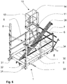
- FIG 6 a different or supplementary application of the work device consisting of work platform 1 and additional platform 10 is shown in a different constellation.
- the work platform 1 itself is penetrated by an assembly support 36 which is arranged in the elevator shaft 4.
- the standing area 5 remains on the work platform and the additional platform 10 can also be arranged laterally on the railing 6 of the work platform 1, which further enables work to be carried out in an upper shaft area.
- the additional platform 10, or its additional standing area 13, can still be reached via the boarding 11 from the work platform.
- the railing of the work platform 1 naturally also includes the rear railing 7.
- the rear railing 7 can be designed essentially identical to the side railing 6.
- the additional platform 10 can also be arranged on the rear railing 7.
- the working platform 1 for its part comprises the floor frame 30 and floor plates which define the standing surface 5 of the working platform 1.
- the base plates are placed on the base frame 30 or are inserted into it.
- the floor frame 30 further includes two lateral floor supports 31, at least one front 33 and one rear cross member 34, which connect the two lateral floor supports 31 to one another, and further at least two intermediate supports 32, which are arranged parallel to the two lateral floor supports 31.
- the two intermediate carriers 32 are essentially carried by the front and rear cross members 33, 34 and they are spaced from one another so far that the assembly carrier 36 can be passed between them.
- the work platform is connected to the structure on the building side via posts 8.
- any other form of work platform 1 can also be used.
- the work platform 1 in the elevator shaft 4 can be built up and fastened to walls using holding shoes, or it can be a mobile work platform 1.
- the additional standing area 13 of the additional platform 10 is shown in each case directly above the railing 6, essentially resting on it.
- the additional standing area 13 can also be arranged at a distance above the railing 6 with an appropriate design.
Landscapes
- Engineering & Computer Science (AREA)
- Architecture (AREA)
- Mechanical Engineering (AREA)
- Civil Engineering (AREA)
- Structural Engineering (AREA)
- Maintenance And Inspection Apparatuses For Elevators (AREA)
- Lift-Guide Devices, And Elevator Ropes And Cables (AREA)
Description
Die vorliegende Erfindung betrifft eine Arbeitseinrichtung zur Ausführung von Montage oder Wartungsarbeiten in einem Aufzugsschacht.The present invention relates to a work device for carrying out assembly or maintenance work in an elevator shaft.
Montagebühnen werden bereits heute zur Montage von Aufzugsausrüstung in einem Aufzugsschacht verwendet. Speziell, um ein Arbeiten in einem oberen Bereich eines Aufzugschachts zu ermöglichen, sind mehrstöckige Montagebühnen bekannt. So schlägt die
Eine derartige Montagebühne ist schwer und aufwändig zu montieren.Such an assembly platform is difficult and complex to assemble.
Die
Mit der vorliegenden Erfindung soll eine alternative Einrichtung zur Ausführung von Arbeiten in einem höher gelegenen Schachtbereich eines Aufzugschachts bereitgestellt werden.The present invention is intended to provide an alternative device for carrying out work in a higher shaft area of an elevator shaft.
Die in dem unabhängigen Patentanspruch definierte Lösung erfüllt zumindest diese Anforderung und sie berücksichtigt mit ihren Ausgestaltungen gemäss den abhängigen Ansprüchen weitere nutzbringende AspekteThe solution defined in the independent patent claim at least fulfills this requirement and, with its configurations according to the dependent claims, it takes into account further beneficial aspects
Gemäss einem Lösungsvorschlag ist die Arbeitseinrichtung ausgeführt, um Montage oder Wartungsarbeiten in einem Aufzugsschacht ausführen zu können. Die Arbeitseinrichtung besteht dazu zumindest aus einer Arbeitsplattform mit einer Standfläche und einem Geländer, wobei die Standfläche Platz für zumindest eine Person bietet und wobei das Geländer die Standfläche zumindest teilweise umschliesst. Weiter umfasst die Arbeitseinrichtung zumindest eine Zusatzplattform. Diese Zusatzplattform ist derart gestaltet, dass sie am Geländer der Arbeitsplattform anbringbar ist oder angebracht werden kann und die Zusatzplattform bietet eine Zusatzstandfläche für zumindest eine Person, wobei die Zusatzstandfläche im montierten Zustand, das heisst, wenn sie am Geländer angebracht ist, oberhalb des Geländers ist.According to one proposed solution, the work device is designed to be able to carry out assembly or maintenance work in an elevator shaft. For this purpose, the work device consists at least of a work platform with a standing surface and a railing, the standing surface offering space for at least one person and the railing at least partially enclosing the standing surface. The work device further comprises at least one additional platform. This additional platform is designed such that it is or can be attached to the railing of the work platform and the Additional platform offers an additional standing area for at least one person, the additional standing area in the assembled state, that is to say when it is attached to the railing, being above the railing.
Dabei ist von Vorteil, dass die Montagebühne, die für ein Arbeiten im Bereich eines Schachtzugangs vorzugsweise im Bereich eines obersten Schachtzugangs ausgelegt ist, einfach erweiterbar ist, um Arbeiten in einem höher gelegenen Schachtbereich zu ermöglichen.The advantage here is that the assembly platform, which is designed for working in the area of a shaft access, preferably in the area of an uppermost shaft access, can be easily expanded in order to enable work in a higher shaft area.
Gemäß der Erfindung ist die Zusatzstandfläche der Zusatzplattform oberhalb des Geländers und von der Standfläche der Arbeitsplattform betrachtet zumindest teilweise, vorteilhafterweise aber im Wesentlichen oder sogar ganz ausserhalb des Geländers angeordnet.According to the invention, the additional standing surface of the additional platform is arranged above the railing and viewed from the standing surface of the work platform at least partially, but advantageously essentially or even completely outside the railing.
Dabei ist von Vorteil, dass die eigentliche Standfläche der Arbeitsplattform eher klein gehalten werden kann. Sie ist beispielsweise auf eine Breite einer Schachtöffnung abgestimmt. Dadurch entstehen jedoch seitlich der Arbeitsplattform Distanzen zu seitlichen Wänden. Dadurch, dass die Zusatzstandfläche der Zusatzplattform zumindest teilweise ausserhalb des Geländers, beziehungsweise ausserhalb der Standfläche der Arbeitsplattform, angeordnet werden kann, kann die Distanz zu seitlichen Wänden verringert werden, wodurch ein sicheres Arbeiten auch in den Bereichen der Schachtwände ermöglicht ist. In einer vorteilhaften Lösung lässt sich eine Lage der Zusatzstandfläche der Zusatzplattform in Bezug auf die Arbeitsplattform verschieben. Dadurch kann flexibel auf jeweilige Abmessungen des Aufzugschachts reagiert werden.The advantage here is that the actual footprint of the work platform can be kept rather small. It is matched, for example, to the width of a shaft opening. However, this creates distances to the side walls on the side of the work platform. Because the additional standing area of the additional platform can be arranged at least partially outside the railing or outside the standing area of the work platform, the distance to the side walls can be reduced, which enables safe working in the areas of the shaft walls. In an advantageous solution, a position of the additional standing area of the additional platform can be shifted in relation to the work platform. This means that it is possible to react flexibly to the respective dimensions of the elevator shaft.
In einer Ausgestaltungsvariante weist die Zusatzplattform eine Umwehrung auf, welche die Zusatzstandfläche im Wesentlichen umschliesst und als Absturzsicherung dient. Dabei ist von Vorteil, dass ein Arbeiter, der die Zusatzplattform betritt geschützt ist, dass er nicht in den Aufzugsschacht fallen kann. Damit ist ein sicheres Arbeiten ermöglicht. In einer Ausgestaltungsvariante weist die Umwehrung eine Zugangspforte auf, welche vorteilhafterweise selbstschliessend ausgeführt ist.In one embodiment, the additional platform has a fence which essentially encloses the additional standing area and serves as a fall protection. The advantage here is that a worker who steps onto the additional platform is protected from being able to fall into the elevator shaft. This enables safe work. In one embodiment, the fence has an access gate, which is advantageously designed to be self-closing.
Dabei ist von Vorteil, dass ein Arbeiter, welche sich auf der Zusatzplattform befindet rundum geschützt ist, so dass er auch nicht in Richtung des Zugangs fallen kann. Bei einer Ausführung mit selbstschliessender Zugangspforte, welche also zum Betreten und Verlassen beispielsweise durch Anheben eines Geländerbalkens bewusst geöffnet werden muss und welche nach dem bewussten Öffnen selbststätig wieder schliesst, ist eine Sicherheit des Arbeitens besonders hoch, da ein Schliessen der Pforte nach Betreten der Zusatzplattform nicht vergessen gehen kann.The advantage here is that a worker who is on the additional platform is protected all around so that he cannot fall in the direction of the access. In the case of a design with a self-closing access gate, which must be consciously opened to enter and exit, for example by lifting a handrail and which automatically closes again after deliberate opening, the safety of work is particularly high, since the gate does not close after stepping on the additional platform can be forgotten.
In einer Ausgestaltungsvariante weist die Zusatzplattform einen Zustieg vorzugsweise eine Leiter auf, welche mit der Zusatzplattform zusammengebaut ist. Die Leiter ermöglicht ein Betreten der Zusatzstandfläche von der Arbeitsplattform her.In one embodiment, the additional platform has an access, preferably a ladder, which is assembled with the additional platform. The ladder enables the additional stand area to be entered from the work platform.
Dabei ist von Vorteil, dass keine separate Leiter oder Ähnliches erforderlich ist, um die Zusatzplattform zu erreichen. Der Zustieg muss nicht gesucht werden, er ist zwangsläufig in die Zusatzplattform integriert. Dadurch entfällt ein Improvisieren und eine Unfallgefahr wird dadurch weiter reduziert.The advantage here is that no separate ladder or the like is required to reach the additional platform. The boarding does not have to be sought, it is inevitably integrated into the additional platform. This eliminates improvising and further reduces the risk of accidents.
In einer Ausgestaltungsvariante ist die Zusatzplattform am Geländer der Arbeitsplattform einhängbar. Unter eingehängt ist hierbei zu verstehen, dass die Zusatzplattform am Geländer gehalten ist, wobei jedoch Belastungskräfte, im Besonderen vertikale Belastungskräfte, in das Geländer eingeleitet oder beispielsweise auch direkt in die Arbeitsplattform eingeleitet werden können. Die Zusatzplattform kann insofern auch auf das Geländer der Arbeitsplattform aufgesetzt sein.In one embodiment, the additional platform can be hung on the railing of the work platform. Suspended here means that the additional platform is held on the railing, but loading forces, in particular vertical loading forces, can be introduced into the railing or, for example, can also be introduced directly into the work platform. In this respect, the additional platform can also be placed on the railing of the work platform.
Dabei ist von Vorteil, dass die Zusatzplattform bedarfsweise angebracht werden kann. Sie muss also nicht andauernd montiert sein, sondern sie kann bei Bedarf an gewünschten Arbeitspositionen auf dem Geländer eingehängt oder auch aufgesetzt werden. Damit behindert die Zusatzplattform andere Anwendungen der Arbeitsplattform nicht.The advantage here is that the additional platform can be attached as required. It does not have to be permanently installed, but can be hung or placed on the railing in the desired working positions if necessary. The additional platform thus does not hinder other applications of the working platform.
In einer Ausgestaltungsvariante ist die Zusatzplattform am Geländer der Arbeitsplattform nach dem Einhängen mittels einer Verriegelung verriegelbar. Vorteilhafterweise beinhaltet die Verriegelung einen selbstschliessenden Riegel, welcher die Zusatzplattform nach dem Einhängen am Geländer selbsttätig verriegelt. Alternativ oder ergänzend erfolgt die Verriegelung mittels eines Sicherungsstifts, eines Riegelstifts oder dergleichen. Vorzugsweise enthält die Verriegelung ein deutlich sichtbares Merkmal, welches den Verriegelungszustand (verriegelt oder entriegelt) anzeigt.In one embodiment, the additional platform can be locked on the railing of the work platform by means of a lock after it has been suspended. Advantageously, the locking includes a self-closing bolt which automatically locks the additional platform after it has been attached to the railing. Alternatively or in addition, the Locking by means of a locking pin, a locking pin or the like. The lock preferably includes a clearly visible feature which indicates the locked state (locked or unlocked).
Dabei ist von Vorteil, dass die Zusatzplattform nicht versehentlich ausgehängt werden kann. Auch dieses erhöht eine Gebrauchssicherheit der Zusatzplattform.The advantage here is that the additional platform cannot be accidentally unhooked. This also increases the safety of use of the additional platform.
In einer Ausgestaltungsvariante ist die Zusatzplattform auf dem Geländer verschiebbar. In dieser Ausgestaltung kann eine Verschiebung erfolgen, ohne dass die Zusatzplattform ausgehängt werden müsste. Hierbei kann beispielsweise durch ein Lösen der Verriegelung ein Seitwärtsverschieben der Zusatzplattform ermöglicht sein.In one embodiment, the additional platform can be moved on the railing. In this embodiment, a shift can take place without the additional platform having to be unhooked. In this case, for example, by releasing the locking mechanism, the additional platform can be moved sideways.
Dabei ist insgesamt von Vorteil, dass die Zusatzplattform einfach zumindest entlang eines geraden Geländerstücks schnell verschoben werden kann. Dadurch kann beispielsweise eine Befestigung oder Einstellung in einem hinteren Bereich des Aufzugschachts ausgeführt werden und anschliessend kann die Zusatzplattform nach vorne verschoben werden, so dass Arbeiten im Bereich einer vorderen Seitenwand des Aufzugschachts ausgeführt werden können. Die Verschiebbarkeit ermöglicht ein Anordnen der Zusatzplattform an gewünschten Arbeitspositionen.The overall advantage here is that the additional platform can easily be moved quickly, at least along a straight railing section. In this way, for example, a fastening or adjustment can be carried out in a rear area of the elevator shaft and then the additional platform can be moved forward so that work can be carried out in the area of a front side wall of the elevator shaft. The displaceability enables the additional platform to be arranged at desired working positions.
In einer Ausgestaltungsvariante umfasst die Zusatzplattform eine Stütze, welche an der Zusatzstandfläche, vorzugsweise an einem äusseren Bereich der Zusatzstandfläche, befestigt ist und welche die Zusatzstandfläche an der Arbeitsplattform stützt.In one embodiment, the additional platform comprises a support which is attached to the additional standing area, preferably to an outer area of the additional standing area, and which supports the additional standing area on the work platform.
Mittels einer derartigen Stütze kann primär eine Belastung des Geländers reduziert werden, was eine leichtere Ausführung des Geländers selbst ermöglicht. Dies ist natürlich kostengünstig und erleichtert eine Montage des Geländers selbst. Vorzugsweise ist die Stütze beispielsweise an der Zusatzplattform vormontiert, so dass sie in eine Stützposition geschwenkt oder verschoben werden kann.A load on the railing can primarily be reduced by means of such a support, which enables the railing itself to be made lighter. This is of course inexpensive and facilitates assembly of the railing itself. The support is preferably preassembled, for example, on the additional platform, so that it can be pivoted or shifted into a support position.
In einer Ausgestaltungsvariante umfasst die Arbeitseinrichtung zwei Zusatzplattformen, wobei die beiden Zusatzplattformen an entgegengesetzten Seiten der Arbeitsplattform anbringbar sind oder angebracht sind. Vorzugsweise sind die Zusatzplattformen identisch, das heisst sie können grundsätzlich überall am Geländer angebracht werden.In one embodiment, the working device comprises two additional platforms, the two additional platforms being or being attached to opposite sides of the working platform. The additional platforms are preferably identical, i.e. they can basically be attached anywhere on the railing.
Dabei ist von Vorteil, dass beispielsweise zwei Personen an entgegengesetzten Seiten des Aufzugschachts gleichzeitig arbeiten können oder gemeinsam ein Bauteil im Aufzugschacht montieren können.The advantage here is that, for example, two people can work on opposite sides of the elevator shaft at the same time or can assemble a component in the elevator shaft together.
In einer Ausgestaltungsvariante ist die Arbeitsplattform der Arbeitseinrichtung eine vorzugsweise temporäre Montagebühne, welche zur Durchführung von Montagearbeiten im Aufzugsschacht, vorzugsweise im Bereich einer obersten Schachtöffnung angeordnet ist.In one embodiment, the work platform of the work device is a preferably temporary assembly platform, which is arranged in the elevator shaft, preferably in the area of an uppermost shaft opening, for carrying out assembly work.
Die Zusatzplattform ist am Geländer dieser Arbeitsplattform angeordnet, um Arbeiten in einem Kopfbereich des Aufzugschachts auszuführen. Die Arbeitsplattform ist beispielsweise so ausgeführt, wie in der Anmeldung
Die
Diese temporäre Montagebühne ist ausgeführt, um im Besonderen mit einem Montageträger zusammenzuwirken, welcher Montagträger zum Anhängen von Aufzugslasten oder von Montagegeräten geeignet ist. Weiter sind in einem Aufzugsschacht Führungsschienen anzuordnen, welche später zur Führung einer Aufzugskabine und eines Gegengewichts verwendet werden sollen. Vielfach werden im Bereich der Schachtdecke dazu Hilfsmittel, wie beispielsweise ein Installationskit, montiert, welche ein genaues Anordnen solcher Führungsschienen ermöglicht. Die Zusatzplattform kann nun zur Anordnung eines derartigen Hilfsmittels vorteilhaft verwendet werden. Damit können beispielsweise Richt- oder Lotschnüre platziert und ausgerichtet werden. Die Zusatzplattform ermöglicht einem Montageteam erforderliche Befestigungs- und Einstellpunkte gefahrlos zu erreichen und die Mitglieder des Montageteams bewegen sich jederzeit in einer sicheren Umgebung.This temporary assembly platform is designed to interact in particular with an assembly carrier, which assembly carrier is suitable for suspending elevator loads or assembly devices. Furthermore, guide rails are to be arranged in an elevator shaft, which are later to be used for guiding an elevator car and a counterweight. In many cases this is done in the area of the shaft ceiling Aids, such as an installation kit, are installed, which enable such guide rails to be arranged precisely. The additional platform can now be used advantageously for the arrangement of such an aid. With this, for example, alignment or plumb lines can be placed and aligned. The additional platform enables an assembly team to safely reach the required fastening and adjustment points and the members of the assembly team can move around in a safe environment at all times.
Eine derartige Arbeitseinrichtung lässt sich aber vielseitig verwenden. Sie kann für Reparaturen im Aufzugsschacht temporär eingebaut und verwendet werden. Bei einer entsprechenden Ausgestaltung eines Geländers einer Aufzugskabine kann die Zusatzplattform auch auf einem Geländer der Aufzugskabine montiert werden, um damit beispielsweise Reparaturen oder Reinigungsarbeiten in einem Schacht-Kopfbereich der Aufzugsanlage durchzuführen.Such a work device can, however, be used in a variety of ways. It can be temporarily installed and used for repairs in the elevator shaft. With a corresponding configuration of a railing of an elevator car, the additional platform can also be mounted on a railing of the elevator car in order, for example, to carry out repairs or cleaning work in a shaft head area of the elevator system.
Im Folgenden werden nun die Erfindungsgedanken anhand eines Beispiels im Zusammenhang mit den Figuren erläutert.In the following, the ideas of the invention will now be explained using an example in connection with the figures.
Es zeigen:
- Figur 1:
- eine Ansicht einer Zusatzplattform mit Anbau an einer Arbeitsplattform,
- Figur 2:
- eine Ansicht einer Arbeitseinrichtung mit Arbeitsplattform und zwei Zusatzplattformen,
- Figur 3:
- eine Detailansicht einer Verriegelung der Zusatzplattform am Geländer der Arbeitsplattform,
- Figur 4:
- einen Anbau der Zusatzplattform an der Arbeitsplattform mit Anbau einer Stütze,
- Figur 5:
- eine Verwendung einer Arbeitseinrichtung mit Arbeitsplattform und Zusatzplattform zum Einbau eines Installationskits,
- Figur 6:
- eine Arbeitseinrichtung mit Arbeitsplattform und einer Zusatzplattform zusammen mit einem Montageträger.
- Figure 1:
- a view of an additional platform with attachment to a work platform,
- Figure 2:
- a view of a work device with a work platform and two additional platforms,
- Figure 3:
- a detailed view of a locking of the additional platform on the railing of the work platform,
- Figure 4:
- an attachment of the additional platform to the work platform with attachment of a support,
- Figure 5:
- Use of a work device with a work platform and additional platform for installing an installation kit,
- Figure 6:
- a work device with a work platform and an additional platform together with an assembly support.
In den Figuren sind für gleichwirkende Teile über alle Figuren hinweg dieselben Bezugszeichen verwendet.In the figures, the same reference symbols are used for parts with the same effect throughout all figures.
Die Zusatzplattform 10 beinhaltet eine Zusatzstandfläche 13, welche so bemessen ist, dass in der Regel eine Person darauf stehen und arbeiten kann. Die Zusatzstandfläche 13 ist oberhalb des Geländers 6 der Arbeitsplattform 1 angeordnet.The
Im Ausführungsbeispiel ist die Zusatzstandfläche 13 der Zusatzplattform 10 zudem so ausgeführt, dass sie von oben betrachtet im Wesentlichen ausserhalb des Geländers 6 angeordnet ist. Sie bildet so eine Arbeitsfläche, welche seitlich über die Standfläche 5 der Arbeitsplattform 1 ragt und welche oberhalb des Geländers 6 angeordnet ist.In the exemplary embodiment, the additional standing
Je nach Anforderung kann die Zusatzplattform auch so ausgeführt sein (nicht dargestellt), dass sie lediglich teilweise ausserhalb des Geländers angeordnet ist und zum anderen Teil von oben betrachtet über der Standfläche 5 der Arbeitsplattform 1 angeordnet ist.Depending on the requirements, the additional platform can also be designed (not shown) in such a way that it is only partially arranged outside the railing and, on the other hand, is arranged above the standing
Die Zusatzstandfläche 13 der Zusatzplattform 10 weist eine Umwehrung 16 auf. Die Umwehrung 16 umschliesst die Zusatzstandfläche 13 auf den von der Arbeitsplattform 1 wegstehenden drei Seiten und bewahrt so eine auf der Zusatzstandfläche 13 arbeitende Person von einem Sturz in einen Aufzugsschacht. Die Umwehrung 16 weist mehrere Umwehrungspfosten 17, 17z auf, welche im Beispiel auf Halterungen an der Zusatzstandfläche 13 aufgesteckt und dort mittels Haltestift 19 fixiert werden. Querverbindungen 23, welche über die Höhe der Umwehrungspfosten 17, 17z angebracht sind, vervollständigen die Umwehrung 16. Auf der der Arbeitsplattform 1 zugewandten Seite der Zusatzstandfläche 13 befindet sich eine Zugangspforte 14. Diese kann manuell geöffnet werden, so dass eine Person die Zusatzstandfläche 13 betreten kann. Im Ausführungsbeispiel von Figur 1 weist die Zusatzstandfläche 13 ausserdem eine Fussschutzleiste 18 auf. Diese schützt ebenso die auf der Zusatzstandfläche 13 stehende Person.The
Bei der Zugangspforte 14 beinhaltet die Zusatzplattform 10 einen Zustieg 11 in der Form eine Leiter 12. Der Zustieg 11 ermöglicht ein Besteigen der Zusatzstandfläche 13. Im Beispiel ist der Zustieg 11, beziehungsweise die Leiter 12, in einer Verlängerung zu den zustiegsseitigen Umwehrungspfosten 17z ausgeführt. An den zustiegsseitigen Umwehrungspfosten 17z ist zudem ein Handlauf 15 angeordnet. Der Handlauf 15 dient primär dem einfacheren Besteigen der Zusatzstandfläche 13, sie kann aber auch zur Befestigung eines Sicherheitsseils dienen, welches die auf der Arbeitsplattform 1 oder der Zusatzplattform 10 arbeitende Person zusätzlich sichert.At the
Über den Zustieg 11 kann die Zusatzplattform 10 am Geländer 6 der Arbeitsplattform 1 eingehängt werden. Dazu befinden sich in einem Bereich nahe der Zusatzstandfläche 13 am Zustieg 11 eine obere Halterung 21, welche dem Einhängen der Zusatzplattform 10 am Geländer 6 dient. Mittels einer oberen Sicherung 22 kann die Zusatzplattform 10 gesichert werden. Die obere Sicherung 22 kann eine Klemmschraube sein oder es kann ein Bolzen sein, der in eine im Geländer vorgesehene Öffnung passt. Grundsätzlich kann der Bolzen auch unterhalb des Geländers durchgestossen werden und so einem versehentlichen Abheben der Zusatzplattform 10 vom Geländer 6 entgegenwirken.The
Entsprechend einer Distanz einer unteren Querstrebe 6u des Geländers 6 ist am Zustieg 11 eine untere Halterung 24 angeordnet, welche, wie im Zusammenhang mit der oberen Halterung 21 erläutert, dem Einhängen der Zusatzplattform 10 am Geländer 6 dient. Im Bereich der unteren Halterung 24 ist weiter eine Verriegelung 20 angebracht. Die Verriegelung 20 sichert die Zusatzplattform 10 gegen ein versehentliches Aushängen. Die Verriegelung 20 ist im Beispiel im Bereich der unteren Halterung 24 angeordnet, sie könnte natürlich auch im Bereich der oberen Halterung 21 sein. Die Verriegelung 20 wird anhand von
Die Verriegelung 20 umfasst als zentrales Element einen Riegel 25. Der Riegel 25 ist über einen Drehpunkt 29 am Zustieg 11, beziehungsweise der Leiter 12, befestigt. Der Riegel 25 weist an seinem unteren Ende einen Haken 25h auf. Wegen der Schwerkraft hängt der Riegel 25 prinzipiell nach unten und er ist so gestaltet, dass der Haken 25h unterhalb der unteren Querstrebe 6u des Geländers 6 einhängt. Der Haken 25h ist an einer, einer Verriegelungsfläche 25v entgegengesetzten Endfläche 25e angeschrägt, so dass der Riegel 25 bei einem aufsetzen der Zusatzplattform 10 auf das Geländer 6, 6u zurückgestossen wird und nach dem erfolgten Aufsetzen, welches durch die untere Halterung 24 bestimmt ist, wieder in seine schwerkraftbestimmte Lage fällt und damit die Zusatzplattform 10 im Wesentlichen selbsttätig verriegelt. Die zwangsläufige Verriegelung kann wunschgemäss durch eine Feder verstärkt werden. Im Beispiel gemäss
Die Zusatzplattform 10 kann auf dem Geländer 6 an einer gewünschten Arbeitsposition platziert werden. Durch ein Lösen von Klemmschrauben oder Bolzen kann die Zusatzplattform auf dem Geländer auch Längsverschoben werden. Die Längsverschiebung ist zumindest soweit einfach möglich, wie keine Geländerpfosten vorhanden sind. Im Bereiche eines Geländerpfostens ist allenfalls ein kurzzeitiges Anheben der Zusatzplattform 10 erforderlich.The
In
Je nach Grösse, Ausgestaltung oder Lastanforderung an die Zusatzplattform 10 ist diese über eine in
Selbstverständlich sind auch hier Sicherungsmassnahmen beispielsweise mittels Stützensicherung 42 vorgesehen, welche die Stütze 40 gegen ein versehentliches Lösen sichert.Of course, securing measures are also provided here, for example by means of support securing means 42, which secure the
Bedarfsgemäss können natürlich mehrere Stützen 40 beispielsweise zumindest zwei Stützen 40 an den beiden äusseren Eckpunkten der Zusatzstandfläche 13 verwendet werden.If necessary,
Die durch die Arbeitsplattform 1 und zumindest einer Zusatzplattform 10 gebildete Arbeitseinrichtung kann nun, wie in
Sofern je eine Person auf den Zusatzplattformen 10 steht, kann das Installationskit 39 gemeinsam angehoben und an entsprechender Position im Aufzugsschacht befestigt werden. Die aus Arbeitsplattform 1 und zumindest einer Zusatzplattform 10 bestehende Arbeitseinrichtung ist geeignet, um Arbeiten in einem Kopfbereich des Aufzugschachts einfach und gefahrlos auszuführen.If one person is standing on the
An den Pfosten 8 sind im Ausführungsbeispiel von
In
Die Arbeitsplattform 1 ihrerseits umfasst den Bodenrahmen 30 sowie Bodenplatten, welche die Standfläche 5 der Arbeitsplattform 1 definieren. Die Bodenplatten sind auf den Bodenrahmen 30 aufgelegt oder in diesen eingelegt sind. Weiter beinhaltet der Bodenrahmen 30 zwei seitliche Bodenträger 31, zumindest einen vorderen 33 und einen hinteren Querträger 34, welche die beiden seitlichen Bodenträger 31 miteinander verbinden, und weiter zumindest zwei Zwischenträger 32, welche parallel zu den beiden seitlichen Bodenträgern 31 angeordnet sind. Die zwei Zwischenträger 32 werden im Wesentlichen vom vorderen und vom hinteren Querträger 33, 34 getragen und sie sind so weit voneinander beabstandet, dass der Montageträger 36 dazwischen durchgeführt werden kann. Analog zu der Ausführung von
Die dargestellten Anordnungen können vom Fachmann weitgehend variiert werden. So kann anstelle einer Arbeitsplattform 1, welche von der Schachtöffnung 3 her in den Aufzugsschacht 4 eingeschoben wird, auch eine beliebige andere Form von Arbeitsplattform 1 verwendet sein. Zum Beispiel kann die Arbeitsplattform 1 im Aufzugsschacht 4 über Halteschuhe an Wänden aufgebaut und befestigt werden oder es kann eine fahrbare Arbeitsbühne 1 sein. In den Beispielen ist die Zusatzstandfläche 13 der Zusatzplattform 10 jeweils direkt über dem Geländer 6, im Wesentlichen auf diesem aufliegend, dargestellt. Die Zusatzstandfläche 13 kann bei entsprechender Auslegung auch in einer Distanz oberhalb des Geländers 6 angeordnet sein.The arrangements shown can largely be varied by those skilled in the art. So Instead of a
Claims (12)
- Working device for carrying out installation or maintenance work in an elevator shaft (4), the working device comprising at least one working platform (1) comprising a standing surface (5) and a railing (6, 7), the standing surface (5) providing space for at least one person and the railing (6, 7) surrounding the standing surface (5) at least in part, characterized in that the working device comprises at least one additional platform (10), it being possible to attach the additional platform (10) to the railing (6, 7) of the working platform (1), and the additional platform (10) providing an additional standing surface (13) for at least one person, which additional standing surface (13) is arranged above the handrail (6), characterized in that the additional standing surface (13), when viewed from the standing surface (5) of the working platform (1), is arranged outside the railing (6) at least in part.
- Working device according to claim 1, characterized in that the additional standing surface (13), when viewed from the standing surface (5) of the working platform (1), is arranged substantially outside the railing (6).
- Working device according to either claim 1 or 2, characterized in that the additional platform (10) has a barrier (16), which substantially encloses the additional standing surface (13) and serves as fall protection.
- Working device according to claim 3, characterized in that the barrier (16) has an access gate (14).
- Working device according to any of claims 1 to 4, characterized in that the additional platform (10) has climbing access (11), preferably a ladder (12), which allows a person to access the additional standing surface (13) from the working platform (1).
- Working device according to any of claims 1 to 5, characterized in that the additional platform (10) can be suspended on the railing (6, 7) of the working platform (1).
- Working device according to claim 6, characterized in that the additional platform (10) can be locked to the railing (6, 7) of the working platform (1) by means of a lock (20) after being suspended.
- Working device according to claim 7, characterized in that the lock (20) contains a self-closing latch (25) which automatically locks the additional platform (10) after being suspended on the railing (6, 7).
- Working device according to any of claims 1 to 8, characterized in that the additional platform (10) is movable on the railing (6, 7).
- Working device according to any of claims 1 to 9, characterized in that the additional platform (10) comprises a support (40) which is fastened to the additional standing surface (13), preferably to an outer region of the additional standing surface (13), and which supports the additional standing surface (13) on the working platform (1).
- Working device according to any of claims 1 to 10, characterized in that the working device comprises two additional platforms (10), the two additional platforms (10) being attachable or attached on opposite sides of the working platform (1).
- Working device according to any of claims 1 to 11, characterized in that the working platform (1) is a temporary installation platform which is preferably arranged in the region of an uppermost shaft opening (3) for carrying out installation work in the elevator shaft (4) and the additional platform (10) is arranged on the railing (6, 7) of the working platform (1) to allow work in the top region of the elevator shaft (4).
Applications Claiming Priority (2)
| Application Number | Priority Date | Filing Date | Title |
|---|---|---|---|
| EP17174315 | 2017-06-02 | ||
| PCT/EP2018/063899 WO2018219851A1 (en) | 2017-06-02 | 2018-05-28 | Additional platform for a working platform |
Publications (2)
| Publication Number | Publication Date |
|---|---|
| EP3630665A1 EP3630665A1 (en) | 2020-04-08 |
| EP3630665B1 true EP3630665B1 (en) | 2021-07-07 |
Family
ID=59014491
Family Applications (1)
| Application Number | Title | Priority Date | Filing Date |
|---|---|---|---|
| EP18725563.3A Active EP3630665B1 (en) | 2017-06-02 | 2018-05-28 | Add-on platform to a work platform |
Country Status (5)
| Country | Link |
|---|---|
| US (1) | US11518651B2 (en) |
| EP (1) | EP3630665B1 (en) |
| CN (1) | CN110709345B (en) |
| ES (1) | ES2884777T3 (en) |
| WO (1) | WO2018219851A1 (en) |
Families Citing this family (1)
| Publication number | Priority date | Publication date | Assignee | Title |
|---|---|---|---|---|
| WO2018219851A1 (en) * | 2017-06-02 | 2018-12-06 | Inventio Ag | Additional platform for a working platform |
Family Cites Families (45)
| Publication number | Priority date | Publication date | Assignee | Title |
|---|---|---|---|---|
| US3232377A (en) * | 1963-06-17 | 1966-02-01 | Baker Roos Inc | Adjustable scaffold |
| JPH0829905B2 (en) * | 1988-03-01 | 1996-03-27 | 株式会社日立ビルシステムサービス | Hoistway scaffolding equipment |
| FR2641018A1 (en) * | 1988-12-22 | 1990-06-29 | Otis Elevator Co | Building-site scaffolding to be climbed in particular in elevator hoppers |
| JPH03120183A (en) | 1989-10-04 | 1991-05-22 | Mitsubishi Electric Corp | Work bench for setting up elevator |
| JP2888394B2 (en) * | 1992-07-14 | 1999-05-10 | 株式会社日立ビルシステム | Elevator work floor |
| GB2274826B (en) * | 1993-02-05 | 1997-03-26 | Scootabout Int Ltd | An apparatus for escalading |
| JP3028926B2 (en) * | 1996-01-16 | 2000-04-04 | 株式会社日立ビルシステム | Scaffolding equipment for elevator installation |
| ES2135358T3 (en) * | 1997-11-08 | 2000-11-01 | Thyssen Aufzugswerke Gmbh | ELEVATOR, ESPECIALLY DRIVING PULLEY ELEVATOR. |
| US6533069B1 (en) * | 2000-11-03 | 2003-03-18 | Richard Couillard | Multi-use ladder support apparatus |
| EP1270489A1 (en) * | 2001-06-27 | 2003-01-02 | Inventio Ag | Erection scaffolding for mounting shaft equipment |
| SG108300A1 (en) * | 2001-06-27 | 2005-01-28 | Inventio Ag | Installing frame for installation of shaft equipment, installing lift with installing frame and method of installation of shaft equipment |
| JP2003261274A (en) * | 2002-03-11 | 2003-09-16 | Mitsubishi Electric Building Techno Service Co Ltd | Lifting rope replacing portable platform of elevator and lifting rope replacing method of elevator using this portable platform |
| JP4260106B2 (en) | 2002-07-12 | 2009-04-30 | シュティングル、ゲゼルシャフト、ミット、ベシュレンクテル、ハフツング | Work platform |
| US20060170224A1 (en) | 2003-02-21 | 2006-08-03 | Mitchell John R S | Hood latch assembly |
| CN100336713C (en) * | 2003-07-22 | 2007-09-12 | 三菱电机株式会社 | Working scaffold device for elevator |
| EP1531210A1 (en) * | 2003-11-13 | 2005-05-18 | Inventio Ag | Working platform for elevator shafts for the installation of elevator components and method for installing an elevator shaft working platform |
| SE526546C2 (en) * | 2004-03-12 | 2005-10-04 | Alimak Ab | Elevator system |
| DE202005015050U1 (en) * | 2005-09-23 | 2007-02-08 | Marantec Antriebs- Und Steuerungstechnik Gmbh & Co. Kg | Door drive with stop protection |
| GB2452269B (en) | 2007-08-29 | 2012-08-01 | Aire Valley Metal Products Ltd | Lift shaft work platform |
| US8646224B2 (en) * | 2008-09-17 | 2014-02-11 | Wurtec Elevator Products & Services | Construction apparatus |
| US9663989B2 (en) * | 2012-01-23 | 2017-05-30 | Wing Enterprises, Inc. | Elevated working platform and related methods |
| CN202897969U (en) * | 2012-10-17 | 2013-04-24 | 卓懋百 | Movable platform of lifer |
| CN202968039U (en) * | 2012-12-12 | 2013-06-05 | 金鹰重型工程机械有限公司 | Telescopic type rotary lifting operation platform |
| US9441382B2 (en) * | 2013-04-15 | 2016-09-13 | Clifford R. Hokanson | Adjustable aircraft maintenance platform for improving efficiency and safety of aircraft maintenance operations |
| US20150181860A1 (en) * | 2013-12-30 | 2015-07-02 | Brian L. Johnson | Treestands |
| EP3107856B1 (en) | 2014-02-21 | 2020-04-22 | Wurtec Elevator Products & Services | False car device |
| CN203729604U (en) * | 2014-03-20 | 2014-07-23 | 北京中联信达金属结构有限公司 | High-altitude protecting guardrail of elevator |
| US20160130115A1 (en) * | 2014-11-07 | 2016-05-12 | Richard C. BLASKA | Retractable overhead access platform for machine room less elevator systems |
| CN104528500B (en) * | 2014-12-29 | 2019-05-14 | 中国建筑股份有限公司 | Double tabletop is without scaffold elevator installing method |
| EP3093262B1 (en) * | 2015-05-12 | 2018-10-31 | KONE Corporation | An arrangement and a method for parallel transport and installation of elevator components |
| CN204626921U (en) | 2015-05-13 | 2015-09-09 | 巨人通力电梯有限公司 | A kind of fixed working platform without scaffold construction elevator |
| CA3000055A1 (en) * | 2015-09-30 | 2017-04-06 | Inventio Ag | Lift system |
| JP6419051B2 (en) * | 2015-10-01 | 2018-11-07 | 三菱電機株式会社 | Elevator installation work scaffolding |
| CN106044656B (en) * | 2016-05-30 | 2018-07-10 | 国网山东省电力公司曹县供电公司 | Horse block device is fixedly mounted in removable ascend a height of substation equipment maintenance and repair work |
| US11598106B2 (en) * | 2017-06-02 | 2023-03-07 | Inventio Ag | Platform for assembling elevator equipment |
| WO2018219851A1 (en) * | 2017-06-02 | 2018-12-06 | Inventio Ag | Additional platform for a working platform |
| US10745968B2 (en) * | 2017-09-14 | 2020-08-18 | Wing Enterprises, Incorporated | Caster assembly and apparatus incorporating same |
| US20190194957A1 (en) * | 2017-12-22 | 2019-06-27 | Wurtec, Incorporated | Telescoping Break-Away Canopy Assembly |
| US20190226217A1 (en) * | 2018-01-24 | 2019-07-25 | Tricam Industries, Inc. | Work platform |
| EP3560878B1 (en) * | 2018-04-27 | 2020-10-21 | Otis Elevator Company | Elevator display systems |
| EP3702309A1 (en) * | 2019-03-01 | 2020-09-02 | Otis Elevator Company | Working platform for an elevator car |
| ES1232990Y (en) * | 2019-04-26 | 2019-10-18 | Prada Javier Lera | PLATFORM FOR WORK IN ELEVATOR HOLES |
| CN110185380A (en) * | 2019-04-30 | 2019-08-30 | 苏州中创铝业有限公司 | A kind of ladder |
| EP3760564B1 (en) * | 2019-07-05 | 2023-05-17 | Otis Elevator Company | Elevator car with working platform stabilisation |
| US11203872B2 (en) * | 2020-02-26 | 2021-12-21 | Dennis J. Hilgendorf | Rolling access step |
-
2018
- 2018-05-28 WO PCT/EP2018/063899 patent/WO2018219851A1/en active Application Filing
- 2018-05-28 ES ES18725563T patent/ES2884777T3/en active Active
- 2018-05-28 EP EP18725563.3A patent/EP3630665B1/en active Active
- 2018-05-28 CN CN201880036633.4A patent/CN110709345B/en active Active
- 2018-05-28 US US16/610,117 patent/US11518651B2/en active Active
Also Published As
| Publication number | Publication date |
|---|---|
| WO2018219851A1 (en) | 2018-12-06 |
| EP3630665A1 (en) | 2020-04-08 |
| US20200079620A1 (en) | 2020-03-12 |
| ES2884777T3 (en) | 2021-12-13 |
| CN110709345B (en) | 2022-05-13 |
| US11518651B2 (en) | 2022-12-06 |
| CN110709345A (en) | 2020-01-17 |
Similar Documents
| Publication | Publication Date | Title |
|---|---|---|
| DE19726408C1 (en) | Working platform for maintenance of wind turbine rotor blades | |
| EP2803616B1 (en) | Working platform device to work in a varying height und method therefor | |
| EP2766292B1 (en) | Lift | |
| EP0922663B1 (en) | Elevator, in particular traction sheave elevator | |
| EP0870722B1 (en) | Maintenance apparatus for elevator car | |
| DE202013007587U1 (en) | Side crash protection for working on roofs, especially flat roofs | |
| CH670394A5 (en) | ||
| EP3630665B1 (en) | Add-on platform to a work platform | |
| DE2729381A1 (en) | CLIMBING ELEVATOR | |
| DE202014000058U1 (en) | Cable guide assembly for the tower of a wind turbine o. | |
| DE102010014787B4 (en) | Solar thermal plant | |
| DE29906047U1 (en) | Fall arrester | |
| DE10009227B4 (en) | locking device | |
| DE10025074B4 (en) | Device for transporting persons | |
| DE2451673A1 (en) | Rescuing appliance for use at great heights - comprises rotary crane with lift coupled to load absorber | |
| DE29718047U1 (en) | Elevator system | |
| EP3440001B1 (en) | Device for evacuating people from an elevator car | |
| DE202020105056U1 (en) | Device for securing a loading point | |
| EP1300529A1 (en) | Security trapdoor for loading station in scaffolding, building opening or the like | |
| DE102015122682B4 (en) | Bauaufzug | |
| EP3560882B1 (en) | Transfer for an elevator | |
| DE202014000273U1 (en) | Elevator system as well as base section, head section and middle section for it | |
| EP3378821A1 (en) | Device for protecting individuals in an elevator shaft against falling objects | |
| DE659112C (en) | Loading device for conveyor wagons with a foldable lifting plate | |
| DE29723595U1 (en) | Working platform |
Legal Events
| Date | Code | Title | Description |
|---|---|---|---|
| STAA | Information on the status of an ep patent application or granted ep patent |
Free format text: STATUS: UNKNOWN |
|
| STAA | Information on the status of an ep patent application or granted ep patent |
Free format text: STATUS: THE INTERNATIONAL PUBLICATION HAS BEEN MADE |
|
| PUAI | Public reference made under article 153(3) epc to a published international application that has entered the european phase |
Free format text: ORIGINAL CODE: 0009012 |
|
| STAA | Information on the status of an ep patent application or granted ep patent |
Free format text: STATUS: REQUEST FOR EXAMINATION WAS MADE |
|
| 17P | Request for examination filed |
Effective date: 20191014 |
|
| AK | Designated contracting states |
Kind code of ref document: A1 Designated state(s): AL AT BE BG CH CY CZ DE DK EE ES FI FR GB GR HR HU IE IS IT LI LT LU LV MC MK MT NL NO PL PT RO RS SE SI SK SM TR |
|
| AX | Request for extension of the european patent |
Extension state: BA ME |
|
| DAV | Request for validation of the european patent (deleted) | ||
| DAX | Request for extension of the european patent (deleted) | ||
| GRAP | Despatch of communication of intention to grant a patent |
Free format text: ORIGINAL CODE: EPIDOSNIGR1 |
|
| STAA | Information on the status of an ep patent application or granted ep patent |
Free format text: STATUS: GRANT OF PATENT IS INTENDED |
|
| INTG | Intention to grant announced |
Effective date: 20210305 |
|
| GRAS | Grant fee paid |
Free format text: ORIGINAL CODE: EPIDOSNIGR3 |
|
| GRAA | (expected) grant |
Free format text: ORIGINAL CODE: 0009210 |
|
| STAA | Information on the status of an ep patent application or granted ep patent |
Free format text: STATUS: THE PATENT HAS BEEN GRANTED |
|
| AK | Designated contracting states |
Kind code of ref document: B1 Designated state(s): AL AT BE BG CH CY CZ DE DK EE ES FI FR GB GR HR HU IE IS IT LI LT LU LV MC MK MT NL NO PL PT RO RS SE SI SK SM TR |
|
| REG | Reference to a national code |
Ref country code: GB Ref legal event code: FG4D Free format text: NOT ENGLISH |
|
| REG | Reference to a national code |
Ref country code: AT Ref legal event code: REF Ref document number: 1408435 Country of ref document: AT Kind code of ref document: T Effective date: 20210715 |
|
| REG | Reference to a national code |
Ref country code: DE Ref legal event code: R096 Ref document number: 502018006036 Country of ref document: DE |
|
| REG | Reference to a national code |
Ref country code: IE Ref legal event code: FG4D Free format text: LANGUAGE OF EP DOCUMENT: GERMAN |
|
| REG | Reference to a national code |
Ref country code: LT Ref legal event code: MG9D |
|
| REG | Reference to a national code |
Ref country code: NL Ref legal event code: MP Effective date: 20210707 |
|
| REG | Reference to a national code |
Ref country code: ES Ref legal event code: FG2A Ref document number: 2884777 Country of ref document: ES Kind code of ref document: T3 Effective date: 20211213 |
|
| PG25 | Lapsed in a contracting state [announced via postgrant information from national office to epo] |
Ref country code: LT Free format text: LAPSE BECAUSE OF FAILURE TO SUBMIT A TRANSLATION OF THE DESCRIPTION OR TO PAY THE FEE WITHIN THE PRESCRIBED TIME-LIMIT Effective date: 20210707 Ref country code: BG Free format text: LAPSE BECAUSE OF FAILURE TO SUBMIT A TRANSLATION OF THE DESCRIPTION OR TO PAY THE FEE WITHIN THE PRESCRIBED TIME-LIMIT Effective date: 20211007 Ref country code: NL Free format text: LAPSE BECAUSE OF FAILURE TO SUBMIT A TRANSLATION OF THE DESCRIPTION OR TO PAY THE FEE WITHIN THE PRESCRIBED TIME-LIMIT Effective date: 20210707 Ref country code: NO Free format text: LAPSE BECAUSE OF FAILURE TO SUBMIT A TRANSLATION OF THE DESCRIPTION OR TO PAY THE FEE WITHIN THE PRESCRIBED TIME-LIMIT Effective date: 20211007 Ref country code: PT Free format text: LAPSE BECAUSE OF FAILURE TO SUBMIT A TRANSLATION OF THE DESCRIPTION OR TO PAY THE FEE WITHIN THE PRESCRIBED TIME-LIMIT Effective date: 20211108 Ref country code: HR Free format text: LAPSE BECAUSE OF FAILURE TO SUBMIT A TRANSLATION OF THE DESCRIPTION OR TO PAY THE FEE WITHIN THE PRESCRIBED TIME-LIMIT Effective date: 20210707 Ref country code: FI Free format text: LAPSE BECAUSE OF FAILURE TO SUBMIT A TRANSLATION OF THE DESCRIPTION OR TO PAY THE FEE WITHIN THE PRESCRIBED TIME-LIMIT Effective date: 20210707 Ref country code: RS Free format text: LAPSE BECAUSE OF FAILURE TO SUBMIT A TRANSLATION OF THE DESCRIPTION OR TO PAY THE FEE WITHIN THE PRESCRIBED TIME-LIMIT Effective date: 20210707 Ref country code: SE Free format text: LAPSE BECAUSE OF FAILURE TO SUBMIT A TRANSLATION OF THE DESCRIPTION OR TO PAY THE FEE WITHIN THE PRESCRIBED TIME-LIMIT Effective date: 20210707 |
|
| PG25 | Lapsed in a contracting state [announced via postgrant information from national office to epo] |
Ref country code: PL Free format text: LAPSE BECAUSE OF FAILURE TO SUBMIT A TRANSLATION OF THE DESCRIPTION OR TO PAY THE FEE WITHIN THE PRESCRIBED TIME-LIMIT Effective date: 20210707 Ref country code: LV Free format text: LAPSE BECAUSE OF FAILURE TO SUBMIT A TRANSLATION OF THE DESCRIPTION OR TO PAY THE FEE WITHIN THE PRESCRIBED TIME-LIMIT Effective date: 20210707 Ref country code: GR Free format text: LAPSE BECAUSE OF FAILURE TO SUBMIT A TRANSLATION OF THE DESCRIPTION OR TO PAY THE FEE WITHIN THE PRESCRIBED TIME-LIMIT Effective date: 20211008 |
|
| REG | Reference to a national code |
Ref country code: DE Ref legal event code: R097 Ref document number: 502018006036 Country of ref document: DE |
|
| PG25 | Lapsed in a contracting state [announced via postgrant information from national office to epo] |
Ref country code: DK Free format text: LAPSE BECAUSE OF FAILURE TO SUBMIT A TRANSLATION OF THE DESCRIPTION OR TO PAY THE FEE WITHIN THE PRESCRIBED TIME-LIMIT Effective date: 20210707 |
|
| PLBE | No opposition filed within time limit |
Free format text: ORIGINAL CODE: 0009261 |
|
| STAA | Information on the status of an ep patent application or granted ep patent |
Free format text: STATUS: NO OPPOSITION FILED WITHIN TIME LIMIT |
|
| PG25 | Lapsed in a contracting state [announced via postgrant information from national office to epo] |
Ref country code: SM Free format text: LAPSE BECAUSE OF FAILURE TO SUBMIT A TRANSLATION OF THE DESCRIPTION OR TO PAY THE FEE WITHIN THE PRESCRIBED TIME-LIMIT Effective date: 20210707 Ref country code: SK Free format text: LAPSE BECAUSE OF FAILURE TO SUBMIT A TRANSLATION OF THE DESCRIPTION OR TO PAY THE FEE WITHIN THE PRESCRIBED TIME-LIMIT Effective date: 20210707 Ref country code: RO Free format text: LAPSE BECAUSE OF FAILURE TO SUBMIT A TRANSLATION OF THE DESCRIPTION OR TO PAY THE FEE WITHIN THE PRESCRIBED TIME-LIMIT Effective date: 20210707 Ref country code: EE Free format text: LAPSE BECAUSE OF FAILURE TO SUBMIT A TRANSLATION OF THE DESCRIPTION OR TO PAY THE FEE WITHIN THE PRESCRIBED TIME-LIMIT Effective date: 20210707 Ref country code: CZ Free format text: LAPSE BECAUSE OF FAILURE TO SUBMIT A TRANSLATION OF THE DESCRIPTION OR TO PAY THE FEE WITHIN THE PRESCRIBED TIME-LIMIT Effective date: 20210707 Ref country code: AL Free format text: LAPSE BECAUSE OF FAILURE TO SUBMIT A TRANSLATION OF THE DESCRIPTION OR TO PAY THE FEE WITHIN THE PRESCRIBED TIME-LIMIT Effective date: 20210707 |
|
| 26N | No opposition filed |
Effective date: 20220408 |
|
| REG | Reference to a national code |
Ref country code: BE Ref legal event code: MM Effective date: 20220531 |
|
| PG25 | Lapsed in a contracting state [announced via postgrant information from national office to epo] |
Ref country code: MC Free format text: LAPSE BECAUSE OF FAILURE TO SUBMIT A TRANSLATION OF THE DESCRIPTION OR TO PAY THE FEE WITHIN THE PRESCRIBED TIME-LIMIT Effective date: 20210707 Ref country code: LU Free format text: LAPSE BECAUSE OF NON-PAYMENT OF DUE FEES Effective date: 20220528 |
|
| PG25 | Lapsed in a contracting state [announced via postgrant information from national office to epo] |
Ref country code: IE Free format text: LAPSE BECAUSE OF NON-PAYMENT OF DUE FEES Effective date: 20220528 |
|
| PG25 | Lapsed in a contracting state [announced via postgrant information from national office to epo] |
Ref country code: BE Free format text: LAPSE BECAUSE OF NON-PAYMENT OF DUE FEES Effective date: 20220531 |
|
| PGFP | Annual fee paid to national office [announced via postgrant information from national office to epo] |
Ref country code: IT Payment date: 20230525 Year of fee payment: 6 |
|
| PG25 | Lapsed in a contracting state [announced via postgrant information from national office to epo] |
Ref country code: MK Free format text: LAPSE BECAUSE OF FAILURE TO SUBMIT A TRANSLATION OF THE DESCRIPTION OR TO PAY THE FEE WITHIN THE PRESCRIBED TIME-LIMIT Effective date: 20210707 Ref country code: CY Free format text: LAPSE BECAUSE OF FAILURE TO SUBMIT A TRANSLATION OF THE DESCRIPTION OR TO PAY THE FEE WITHIN THE PRESCRIBED TIME-LIMIT Effective date: 20210707 |
|
| PG25 | Lapsed in a contracting state [announced via postgrant information from national office to epo] |
Ref country code: HU Free format text: LAPSE BECAUSE OF FAILURE TO SUBMIT A TRANSLATION OF THE DESCRIPTION OR TO PAY THE FEE WITHIN THE PRESCRIBED TIME-LIMIT; INVALID AB INITIO Effective date: 20180528 |
|
| PG25 | Lapsed in a contracting state [announced via postgrant information from national office to epo] |
Ref country code: TR Free format text: LAPSE BECAUSE OF FAILURE TO SUBMIT A TRANSLATION OF THE DESCRIPTION OR TO PAY THE FEE WITHIN THE PRESCRIBED TIME-LIMIT Effective date: 20210707 |
|
| PGFP | Annual fee paid to national office [announced via postgrant information from national office to epo] |
Ref country code: GB Payment date: 20240521 Year of fee payment: 7 |
|
| PGFP | Annual fee paid to national office [announced via postgrant information from national office to epo] |
Ref country code: DE Payment date: 20240529 Year of fee payment: 7 |
|
| PGFP | Annual fee paid to national office [announced via postgrant information from national office to epo] |
Ref country code: CH Payment date: 20240602 Year of fee payment: 7 |
|
| PGFP | Annual fee paid to national office [announced via postgrant information from national office to epo] |
Ref country code: ES Payment date: 20240610 Year of fee payment: 7 |
|
| PGFP | Annual fee paid to national office [announced via postgrant information from national office to epo] |
Ref country code: AT Payment date: 20240521 Year of fee payment: 7 |
|
| PGFP | Annual fee paid to national office [announced via postgrant information from national office to epo] |
Ref country code: FR Payment date: 20240527 Year of fee payment: 7 |