EP4337421B1 - Heftklammergerät - Google Patents
Heftklammergerät Download PDFInfo
- Publication number
- EP4337421B1 EP4337421B1 EP22769933.7A EP22769933A EP4337421B1 EP 4337421 B1 EP4337421 B1 EP 4337421B1 EP 22769933 A EP22769933 A EP 22769933A EP 4337421 B1 EP4337421 B1 EP 4337421B1
- Authority
- EP
- European Patent Office
- Prior art keywords
- anvil
- staple magazine
- stapling device
- driver
- leg
- Prior art date
- Legal status (The legal status is an assumption and is not a legal conclusion. Google has not performed a legal analysis and makes no representation as to the accuracy of the status listed.)
- Active
Links
Images



Classifications
-
- B—PERFORMING OPERATIONS; TRANSPORTING
- B25—HAND TOOLS; PORTABLE POWER-DRIVEN TOOLS; MANIPULATORS
- B25C—HAND-HELD NAILING OR STAPLING TOOLS; MANUALLY OPERATED PORTABLE STAPLING TOOLS
- B25C5/00—Manually operated portable stapling tools; Hand-held power-operated stapling tools; Staple feeding devices therefor
- B25C5/02—Manually operated portable stapling tools; Hand-held power-operated stapling tools; Staple feeding devices therefor with provision for bending the ends of the staples on to the work
- B25C5/0221—Stapling tools of the table model type, i.e. tools supported by a table or the work during operation
- B25C5/0228—Stapling tools of the table model type, i.e. tools supported by a table or the work during operation power-operated
-
- B—PERFORMING OPERATIONS; TRANSPORTING
- B25—HAND TOOLS; PORTABLE POWER-DRIVEN TOOLS; MANIPULATORS
- B25C—HAND-HELD NAILING OR STAPLING TOOLS; MANUALLY OPERATED PORTABLE STAPLING TOOLS
- B25C5/00—Manually operated portable stapling tools; Hand-held power-operated stapling tools; Staple feeding devices therefor
- B25C5/02—Manually operated portable stapling tools; Hand-held power-operated stapling tools; Staple feeding devices therefor with provision for bending the ends of the staples on to the work
- B25C5/0221—Stapling tools of the table model type, i.e. tools supported by a table or the work during operation
- B25C5/0242—Stapling tools of the table model type, i.e. tools supported by a table or the work during operation having a pivoting upper leg and a leg provided with an anvil supported by the table or work
-
- B—PERFORMING OPERATIONS; TRANSPORTING
- B25—HAND TOOLS; PORTABLE POWER-DRIVEN TOOLS; MANIPULATORS
- B25C—HAND-HELD NAILING OR STAPLING TOOLS; MANUALLY OPERATED PORTABLE STAPLING TOOLS
- B25C5/00—Manually operated portable stapling tools; Hand-held power-operated stapling tools; Staple feeding devices therefor
- B25C5/10—Driving means
- B25C5/15—Driving means operated by electric power
Definitions
- the invention relates to a stapler according to the preamble of claim 1.
- Such staplers which are also known as magnetic staplers, are characterized by the fact that the staples are driven through the sheet material to be stapled not by manually pressing down the driver, but by the driver being actuated by the actuating device.
- the firing pin is drawn into the magnetic coil by energizing it and, in doing so, acts on the driver anvil with an actuating element, so that the driver is moved abruptly downwards and drives the frontmost staple in the staple magazine through the gap so that it can penetrate the sheet material lying on the anvil.
- the driver moves against the restoring force of a driver spring.
- the staple magazine is also supported on the anvil leg by means of a magazine spring, whereby the magazine spring is weaker than the driver spring. This means that during the stapling process, the front end of the staple magazine, which has the gap, is pressed onto the anvil before the driver is moved downwards.
- a common disadvantage of such conventional magnetic staplers is the loud noises that occur during the stapling process. This occurs particularly when the staple cartridge impacts the anvil plate or the sheet material resting on the anvil plate.
- the invention is based on the idea of at least largely avoiding the noise generated when the staple magazine impacts the sheet material by having the staple magazine already rest on the anvil leg or anvil plate when the stapling process is triggered.
- the force of the firing pin then no longer strikes the anvil plate or anvil leg at high speed, but at most moves it a short distance towards the anvil.
- the staple magazine rests on the anvil leg or anvil plate in its resting state, i.e. in the absence of external forces, it can also be raised slightly, particularly for inserting sheet material between the staple magazine and the anvil plate.
- the staple magazine expediently has a spacer on its underside facing the anvil leg, which rests on the anvil leg or the anvil plate in the absence of external forces.
- the staple magazine then does not rest directly with its base on the anvil leg or the anvil plate, but with the spacer.
- This can be a plate that extends over part of the length of the staple magazine between the gap and the transverse axis.
- the spacer is elastically compressible and is made, for example, of rubber. This embodiment is particularly advantageous when the gap is arranged at a distance above the anvil plate in the absence of external forces, for example to facilitate the insertion of sheet material between the anvil plate and the staple magazine.
- the stapler conveniently features a guide for inserting sheets between the staple cartridge and the anvil plate.
- This guide has a sloped rearward direction. This guide facilitates the insertion of sheets without having to deliberately lift the staple cartridge.
- the insertion aid is attached to the staple magazine and projects forward from it.
- the insertion aid can be designed, for example, as a wire bracket or as a plastic part. In the first embodiment, it can expediently be lifted relative to the staple magazine against a restoring force.
- the stapler can also have a hood that covers the staple magazine and accommodates the actuating device, so that the risk of a user placing a finger between the staple magazine and the anvil plate and being injured during the stapling process is minimized.
- the hood can have a flap on its front that can be pivoted to a limited extent and that covers the insertion aid in a first end position and releases the insertion aid in a second end position.
- the insertion aid is formed by a sloping, rearwardly sloping surface of the hood covering the staple magazine and accommodating the actuating device.
- the hood it is preferred that the hood not have a pivoting flap, but always completely cover the staple magazine.
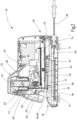
- the stapler 10 according to the first embodiment shown in FIG. 1 has, like the one shown in Fig. 3 , 4
- the stapler 10' shown according to the second embodiment has an anvil leg 12, on the underside of which feet 14 are arranged for placement on a surface, such as a table top, and in the front region 16 of which an anvil plate 18 is arranged on the upper side facing away from the underside, which anvil plate has forming contours for forming staple legs.
- a transverse axis 22 is arranged, about which a staple magazine 24 is pivotally mounted relative to the anvil leg 12.
- the staple magazine 24 has a gap 28 on its underside facing the anvil leg 12, through which the foremost of the staples held in the staple magazine 24 can be passed by means of a vertically displaceable driver 30 and driven through the sheet material to be stapled lying on the anvil plate 18.
- the stapler 10, 10' also has a hood 32, which is connected to the anvil leg 12 and covers the staple magazine 24.
- the hood 32 also houses the driver 30 together with an actuating device 34.
- This has a magnetic coil 36, which is supplied with power via a connecting cable 38.
- a firing pin 40 is mounted in the magnetic coil 36 so as to be displaceable in a substantially vertical direction.
- the firing pin 40 has a magnetic section 42 projecting upwards from the magnetic coil 36, which comprises a ferromagnetic material, as well as a Striking section 44 made of plastic.
- a driver anvil 46 Arranged beneath the firing pin 40 is a driver anvil 46, which is firmly connected to the driver 30 and supported on the staple magazine 24 by a driver spring 48 in the form of a compression spring.
- the magnetic coil 36 When the magnetic coil 36 is energized, the magnetic section 42 is suddenly drawn into it, so that the striking section 44 strikes the driver anvil 46 and suddenly pushes the driver 30 downward against the force of the driver spring 48.
- the driver 30 then acts on the staple arranged at the front in the staple magazine 24, causing it to pass through the gap 28 and be driven through the sheet material lying on the anvil plate 18, where it is formed along the forming contours.
- the staple magazine 24 is supported on the anvil leg 12 by means of a magazine spring 50, also designed as a compression spring.
- the magazine spring 50 is designed to be considerably weaker than the driver spring 48 and has a significantly lower spring constant. It is arranged between the front end 26 and the transverse axis 22 and is dimensioned such that it cannot keep the staple magazine 24 suspended above the anvil leg 12.
- the staple magazine 24 is located in the Fig. 1 , 3 shown rest position, in which no external forces act on the stapler 10, with a spacer 54 in the form of a rubber plate arranged on its underside 52 on the anvil leg 12.
- the spacer 54 is arranged between the gap 28 and the transverse axis 22, so that in the rest position the gap 28 is held at a small distance above the anvil plate 18.
- the spacer 54 is first compressed and the magazine spring 50 is shortened a little further until the front end 26 of the staple magazine 24 rests on the anvil plate 18 or on the sheet material lying on the anvil plate 18. Since no further downward movement of the staple magazine 24 is then possible, the driver 30 is moved downward against the restoring force of the driver spring 48 and the sheet material is stapled together.
- the staplers 10, 10' according to the two embodiments are identical with regard to the features described above and their functioning resulting from these features. To better illustrate how they work, they are shown in Fig. 2 , 4 also shown with the staple magazine 24 raised.
- the staplers 10, 10' also each have an insertion aid 56 with a slope 58 sloping backwards towards the anvil leg 12, which facilitates the insertion of sheet material under the gap 28.
- the slope 58 is formed by a wire bracket 60 fastened to the front end 26 of the staple magazine 24, which is also arranged under the hood 32.
- the hood 32 has a flap 62 on its front side, which is pivotable to a limited extent and covers the wire bracket 60 in a first end position and in a second end position, which Fig. 1 , 2 is shown.
- the bevel 58 is formed by a front surface 64 of the hood 32.
- the invention relates to a stapler 10, 10' with an anvil leg 12 carrying an anvil plate 18 in its front region 16, with a staple magazine 24 which is pivotable to a limited extent with respect to the anvil leg 12 about a transverse axis 22 arranged in the rear region 20 of the anvil leg 12, with a driver 30 for feeding staples through a gap 28 arranged above the anvil plate 18 at the front end 26 of the staple magazine 24 and with an actuating device 34 for acting on the driver 30 in the direction of the anvil plate 18 against the restoring force of a driver spring 48, wherein the actuating device 34 has a magnetic coil 36 and a firing pin 40 which is movable by means of the magnetic coil 36 for acting on a driver anvil 46 which is firmly connected to the driver 30, and wherein the staple magazine 24 between the gap 28 and the transverse axis 22 is supported on the anvil leg 12 by means of a magazine spring 50.
- the magazine spring 50 is dimensioned such that the staple magazine 24
Landscapes
- Engineering & Computer Science (AREA)
- Mechanical Engineering (AREA)
- Portable Nailing Machines And Staplers (AREA)
- Dovetailed Work, And Nailing Machines And Stapling Machines For Wood (AREA)
Description
- Die Erfindung betrifft ein Heftklammergerät gemäß Oberbergriff des Anspruchs 1.
- Solche Heftklammergeräte (vgl.
US 2021/0205970 A1 ), die auch als Magnet-Heftgeräte bezeichnet werden, zeichnen sich dadurch aus, dass das Durchtreiben der Heftklammern durch das zu heftende Blattgut nicht durch manuelles Niederdrücken des Treibers erfolgt, sondern durch Beaufschlagung des Treibers durch die Betätigungseinrichtung. Beim Heftvorgang wird durch Bestromung der Magnetspule der Schlagbolzen in diese hineingezogen und beaufschlagt dabei mit einem Betätigungselement den Treiberamboß, so dass der Treiber ruckartig nach unten bewegt wird und die vorderste Heftklammer im Klammermagazin durch den Spalt treibt, so dass sie das auf dem Amboß liegende Blattgut durchdringen kann. Die Bewegung des Treibers erfolgt gegen die Rückstellkraft einer Treiberfeder. Das Klammermagazin ist zudem mittels einer Magazinfeder auf dem Amboßschenkel abgestützt, wobei die Magazinfeder schwächer ausgeführt ist als die Treiberfeder. Damit wird beim Heftvorgang erst das Klammermagazin mit seinem den Spalt aufweisenden Vorderende auf den Amboß gedrückt, bevor der Treiber nach unten bewegt wird. - Als nachteilig an solchen vorbekannten Magnet-Heftgeräten wird regelmäßig empfunden, dass beim Heftvorgang laute Geräusche auftreten. Diese treten insbesondere dann auf, wenn das Klammermagazin auf der Amboßplatte bzw. auf dem auf der Amboßplatte liegenden Blattgut aufprallt.
- Es ist daher Aufgabe der Erfindung, ein Heftklammergerät der eingangs genannten Art derart weiterzuentwickeln, dass der Heftvorgang weniger Lärm verursacht.
- Diese Aufgabe wird erfindungsgemäß durch ein Heftklammergerät mit den Merkmalen des Anspruchs 1 gelöst. Vorteilhafte Weiterbildungen der Erfindung sind Gegenstand der abhängigen Ansprüche.
- Der Erfindung liegt der Gedanke zugrunde, das beim Aufprall des Klammermagazins auf das Blattgut entstehende Geräusch zumindest weitgehend dadurch zu vermeiden, dass das Klammermagazin beim Auslösen des Heftvorgangs bereits auf dem Amboßschenkel oder auf der Amboßplatte aufliegt. Es wird dann durch die Kraft des Schlagbolzens nicht mehr mit hoher Geschwindigkeit auf die Amboßplatte oder den Amboßschenkel geschlagen, sondern allenfalls noch ein Stück weit auf den Amboß zu bewegt. Während das Klammermagazin im Ruhezustand, also bei Fehlen äußerer Kräfte, auf dem Amboßschenkel oder auf der Amboßplatte aufliegt, kann es, insbesondere zum Einführen von Blattgut zwischen das Klammermagazin und die Amboßplatte, auch ein Stück weit angehoben werden.
- Zweckmäßig weist das Klammermagazin an seiner dem Amboßschenkel zugewandten Unterseite einen Abstandshalter auf, der bei Fehlen äußerer Kräfte auf dem Ambobssschenkel oder der Amboßplatte aufliegt. Das Klammermagazin liegt dann nicht direkt mit seinem Boden auf dem Amboßschenkel oder der Amboßplatte auf, sondern mit dem Abstandshalter. Dieser kann eine Platte sein, die sich über einen Teil der Länge des Klammermagazins zwischen dem Spalt und der Querachse erstreckt. Gemäß einem vorteilhaften Ausführungsbeispiel ist der Abstandshalter elastisch kompressibel und ist beispielsweise aus Gummi gefertigt. Diese Ausführungsform ist insbesondere dann vorteilhaft, wenn der Spalt bei Fehlen äußerer Kräfte im Abstand über der Amboßplatte angeordnet ist, beispielsweise um das Einführen von Blattgut zwischen der Amboßplatte und dem Klammermagazin zu erleichtern. Es ist dann beispielsweise möglich, den Spalt durch Kompression des Abstandshalters auf die Amboßplatte abzusenken. Indem der Abstandshalter bereits auf dem Amboßschenkel oder der Amboßplatte aufliegt, wenn der Heftvorgang ausgelöst wird, wird das geräuschintensive Aufschlagen des Klammermagazins auf dem Amboßschenkel oder der Amboßplatte vermieden.
- Zweckmäßig weist das Heftklammergerät eine Einführhilfe zum Einführen von Blattgut zwischen dem Klammermagazin und der Amboßplatte auf, welche eine nach hinten abfallende Schräge aufweist. Die Einführhilfe erleichtert das Einführen von Blattgut, ohne dass hierfür das Klammermagazin gezielt angehoben werden muss.
- Gemäß einer ersten Ausführungsform ist die Einführhilfe am Klammermagazin befestigt und steht von diesem nach vorne ab. Die Einführhilfe kann beispielsweise als Drahtbügel oder auch als Kunststoffteil ausgeführt sein. Zweckmäßig ist sie bei der ersten Ausführungsform gegen eine Rückstellkraft bezüglich des Klammermagazins anhebbar. Es ist zudem möglich, dass das Heftklammergerät eine das Klammermagazin überdeckende und die Betätigungseinrichtung aufnehmende Haube aufweist, so dass die Gefahr, dass ein Benutzer einen Finger zwischen das Klammermagazin und die Amboßplatte bringt und beim Heftvorgang verletzt wird, minimiert wird. Die Haube kann an ihrer Vorderseite eine begrenzt verschwenkbare Klappe aufweisen, die in einer ersten Endstellung die Einführhilfe überdeckt und die Einführhilfe in einer zweiten Endstellung freigibt.
- Gemäß einer zweiten Ausführungsform wird die Einführhilfe durch eine schräg nach hinten abfallende Fläche der das Klammermagazin überdeckenden und die Betätigungseinrichtung aufnehmenden Haube gebildet. Es wird bei der zweiten Ausführungsform bevorzugt, dass die Haube keine verschwenkbare Klappe aufweist, sondern das Klammermagazin stets vollständig überdeckt.
- Im Folgenden wird die Erfindung anhand zweier in der Zeichnung schematisch dargestellter Ausführungsbeispiele näher erläutert. Es zeigen
- Fig. 1, 2
- ein Heftklammergerät im Längsschnitt gemäß einem ersten Ausführungsbeispiel in einer Ruheposition und mit hochgehobenem Klammermagazin und
- Fig. 3, 4
- ein Heftklammergerät gemäß einem zweiten Ausführungsbeispiel im Längsschnitt in Ruheposition und mit hochgehobenem Klammermagazin.
- Das in
Fig. 1 ,2 dargestellte Heftklammergerät 10 gemäß dem ersten Ausführungsbeispiel weist ebenso wie das inFig. 3 ,4 dargestellte Heftklammergerät 10' gemäß dem zweiten Ausführungsbeispiel einen Amboßschenkel 12 auf, an dessen Unterseite Füße 14 zum Aufstellen auf eine Oberfläche, wie beispielsweise eine Tischplatte, angeordnet sind, und in dessen vorderem Bereich 16 an der der Unterseite abgewandten Oberseite eine Amboßplatte 18 angeordnet ist, welche Umformkonturen zum Umformen von Heftklammerschenkeln aufweist. Im hinteren Bereich 20 des Amboßschenkels 12 ist eine Querachse 22 angeordnet, um die ein Klammermagazin 24 begrenzt gegenüber dem Amboßschenkel 12 verschwenkbar gelagert ist. An seinem Vorderende 26 weist das Klammermagazin 24 an seiner dem Amboßschenkel 12 zugewandten Unterseite einen Spalt 28 auf, durch den die jeweils vorderste der im Klammermagazin 24 aufgenommenen Heftklammern mittels eines vertikal verschieblichen Treibers 30 durchgeführt und durch auf der Amboßplatte 18 liegendes, zu heftendes Blattgut hindurchgetrieben werden kann. - Das Heftklammergerät 10, 10' weist zudem eine Haube 32 auf, die mit dem Amboßschenkel 12 verbunden ist und das Klammermagazin 24 überdeckt. In der Haube 32 ist zudem der Treiber 30 zusammen mit einer Betätigungseinrichtung 34 aufgenommen. Diese weist eine Magnetspule 36 auf, die über ein Anschlußkabel 38 mit Strom versorgt wird. In der Magnetspule 36 ist ein Schlagbolzen 40 in im Wesentlichen vertikaler Richtung verschieblich gelagert, der eine nach oben aus der Magnetspule 36 ragende Magnetpartie 42 aufweist, welche einen ferromagnetischen Werkstoff aufweist, sowie eine unten aus der Magnetspule 36 ragende Schlagpartie 44 aus Kunststoff. Unter dem Schlagbolzen 40 ist ein fest mit dem Treiber 30 verbundener Treiberamboß 46 angeordnet, der mittels einer Treiberfeder 48 in Form einer Druckfeder auf dem Klammermagazin 24 abgestützt ist. Wird die Magnetspule 36 bestromt, so wird die Magnetpartie 42 schlagartig in sie eingezogen, so dass die Schlagpartie 44 auf den Treiberamboß 46 schlägt und den Treiber 30 gegen die Kraft der Treiberfeder 48 schlagartig nach unten drängt. Der Treiber 30 beaufschlagt dann die im Klammermagazin 24 zuvorderst angeordnete Heftklammer, so dass diese durch den Spalt 28 durchgeführt und durch das auf der Amboßplatte 18 liegende Blattgut hindurchgetrieben und in den Umformkonturen umgeformt wird.
- Das Klammermagazin 24 ist mittels einer ebenfalls als Druckfeder ausgebildeten Magazinfeder 50 am Amboßschenkel 12 abgestützt. Die Magazinfeder 50 ist dabei wesentlich schwächer ausgeführt als die Treiberfeder 48 und weist eine deutlich kleinere Federkonstante auf. Sie ist zwischen dem Vorderende 26 und der Querachse 22 angeordnet und so dimensioniert, dass sie das Klammermagazin 24 nicht über dem Amboßschenkel 12 in der Schwebe halten kann. Das Klammermagazin 24 liegt in der in
Fig. 1 ,3 gezeigten Ruhestellung, in der keine äußeren Kräfte auf das Heftklammergerät 10 wirken, mit einem an seiner Unterseite 52 angeordneten Abstandshalter 54 in Form einer Gummiplatte auf dem Amboßschenkel 12 auf. Der Abstandshalter 54 ist dabei zwischen dem Spalt 28 und der Querachse 22 angeordnet, so dass in der Ruhestellung der Spalt 28 in einem geringen Abstand über der Amboßplatte 18 gehalten wird. Wird die Betätigungseinrichtung 34 durch Bestromen der Magnetspule 36 betätigt, so wird zunächst der Abstandshalter 54 komprimiert und die Magazinfeder 50 noch ein Stück verkürzt, bis das Vorderende 26 des Klammermagazins 24 auf der Amboßplatte 18 bzw. auf dem auf der Amboßplatte 18 liegenden Blattgut aufliegt. Da dann keine weitere Abwärtsbewegung des Klammermagazins 24 mehr möglich ist, wird der Treiber 30 gegen die Rückstellkraft der Treiberfeder 48 nach unten bewegt, und das Blattgut wird zusammengeheftet. Die Heftklammergeräte 10, 10' gemäß den beiden Ausführungsbeispielen sind im Hinblick auf die oben beschriebenen Merkmale und ihre aus diesen Merkmalen resultierende Funktionsweise identisch. Zur besseren Veranschaulichung ihrer Funktionsweise sind sie inFig. 2 ,4 zudem mit hochgehobenem Klammermagazin 24 dargestellt. - Die Heftklammergeräte 10, 10' gemäß den beiden Ausführungsbeispielen weisen zudem jeweils eine Einführhilfe 56 mit einer schräg nach hinten auf den Amboßschenkel 12 zu abfallenden Schräge 58 auf, die das Einführen von Blattgut unter den Spalt 28 erleichtert. Beim Heftklammergerät 10 gemäß dem ersten Ausführungsbeispiel wird die Schräge 58 durch einen am Vorderende 26 des Klammermagazins 24 befestigten Drahtbügel 60 gebildet, der ebenfalls unter der Haube 32 angeordnet ist. Die Haube 32 weist dabei eine Klappe 62 an ihrer Vorderseite auf, welche begrenzt verschwenkbar ist und in einer ersten Endstellung den Drahtbügel 60 überdeckt und in einer zweiten Endstellung, welche in
Fig. 1 ,2 dargestellt ist, freigibt. Wird die Klappe 62 aus ihrer ersten Endstellung herausbewegt, so wird ein in der Zeichnung nicht dargestellter Schalter betätigt, der ein Bestromen der Magnetspule 36 verhindert, so dass sich eine unter den Drahtbügel 60 fassende Person nicht durch das versehentliche Auslösen eines Heftvorgangs verletzen kann. Beim Heftklammergerät 10' gemäß dem zweiten Ausführungsbeispiel dagegen wird die Schräge 58 durch eine Vorderfläche 64 der Haube 32 gebildet. - Zusammenfassend ist folgendes festzuhalten: Die Erfindung betrifft ein Heftklammergerät 10, 10' mit einem in seinem vorderen Bereich 16 eine Amboßplatte 18 tragenden Amboßschenkel 12, mit einem um eine im hinteren Bereich 20 des Amboßschenkels 12 angeordnete Querachse 22 bezüglich des Amboßschenkels 12 begrenzt verschwenkbaren Klammermagazin 24, mit einem Treiber 30 zum Durchführen von Heftklammern durch einen über der Amboßplatte 18 angeordneten Spalt 28 am Vorderende 26 des Klammermagazins 24 und mit einer Betätigungseinrichtung 34 zur Beaufschlagung des Treibers 30 in Richtung zur Amboßplatte 18 gegen die Rückstellkraft einer Treiberfeder 48, wobei die Betätigungseinrichtung 34 eine Magnetspule 36 sowie einen mittels der Magnetspule 36 beweglichen Schlagbolzen 40 zum Beaufschlagen eines fest mit dem Treiber 30 verbundenen Treiberamboßes 46 aufweist und wobei das Klammermagazin 24 zwischen dem Spalt 28 und der Querachse 22 mittels einer Magazinfeder 50 auf dem Amboßschenkel 12 abgestützt ist. Erfindungsgemäß ist vorgesehen, dass die Magazinfeder 50 so dimensioniert ist, dass das Klammermagazin 24 bei Fehlen äußerer Kräfte auf dem Amboßschenkel 12 oder auf der Amboßplatte 18 aufliegt.
Claims (12)
- Heftklammergerät mit einem in seinem vorderen Bereich (16) eine Amboßplatte (18) tragenden Amboßschenkel (12), mit einem um eine im hinteren Bereich (20) des Amboßschenkels (12) angeordnete Querachse (22) bezüglich des Amboßschenkels (12) begrenzt verschwenkbaren Klammermagazin (24), mit einem Treiber (30) zum Durchführen von Heftklammern durch einen über der Amboßplatte (18) angeordneten Spalt (28) am Vorderende (26) des Klammermagazins (24) und mit einer Betätigungseinrichtung (34) zur Beaufschlagung des Treibers (30) in Richtung zur Amboßplatte (18) gegen die Rückstellkraft einer Treiberfeder (48), wobei die Betätigungseinrichtung (34) eine Magnetspule (36) sowie einen mittels der Magnetspule (36) beweglichen Schlagbolzen (40) zum Beaufschlagen eines fest mit dem Treiber (30) verbundenen Treiberamboßes (46) aufweist und wobei das Klammermagazin (24) zwischen dem Spalt (28) und der Querachse (22) mittels einer Magazinfeder (50) auf dem Amboßschenkel (12) abgestützt ist, dadurch gekennzeichnet, dass die Magazinfeder (50) so dimensioniert ist, dass das Klammermagazin (24) bei Fehlen äußerer Kräfte auf dem Amboßschenkel (12) oder auf der Amboßplatte (18) aufliegt.
- Heftklammergerät nach Anspruch 1, dadurch gekennzeichnet, dass das Klammermagazin (24) an seiner dem Amboßschenkel (12) zugewandten Unterseite (52) einen Abstandshalter (54) aufweist, der bei Fehlen äußerer Kräfte auf dem Amboßschenkel (12) oder der Amboßplatte (18) aufliegt.
- Heftklammergerät nach Anspruch 2, dadurch gekennzeichnet, dass der Abstandshalter (54) eine Platte ist, die sich über einen Teil der Länge des Klammermagazins (24) zwischen dem Spalt (28) und der Querachse (22) erstreckt.
- Heftklammergerät nach Anspruch 2 oder 3, dadurch gekennzeichnet, dass der Abstandshalter (54) elastisch kompressibel ist.
- Heftklammergerät nach einem der vorangehenden Ansprüche, dadurch gekennzeichnet, dass der Spalt (28) bei Fehlen äußerer Kräfte im Abstand über der Amboßplatte (18) angeordnet ist.
- Heftklammergerät nach Anspruch 4 und nach Anspruch 5, dadurch gekennzeichnet, dass der Spalt (28) durch Kompression des Abstandshalters (54) auf die Amboßplatte (18) absenkbar ist.
- Heftklammergerät nach einem der vorangehenden Ansprüche, gekennzeichnet durch eine Einführhilfe (56) zum Einführen von Blattgut zwischen dem Klammermagazin (24) und der Amboßplatte (18), welche eine nach hinten abfallende Schräge (58) aufweist.
- Heftklammergerät nach Anspruch 7, dadurch gekennzeichnet, dass die Einführhilfe (56) am Klammermagazin (24) befestigt ist und von diesem nach vorne absteht.
- Heftklammergerät nach Anspruch 8, dadurch gekennzeichnet, dass die Einführhilfe (56) gegen eine Rückstellkraft bezüglich des Klammermagazins (24) anhebbar ist.
- Heftklammergerät nach einem der vorangehenden Ansprüche, gekennzeichnet durch eine das Klammermagazin (24) überdeckende und die Betätigungseinrichtung (34) aufnehmende Haube (32).
- Heftklammergerät nach Anspruch 10, dadurch gekennzeichnet, dass die Haube (32) an ihrer Vorderseite eine begrenzt verschwenkbare Klappe (62) aufweist, die in einer ersten Endstellung die Einführhilfe (56) überdeckt und diese in einer zweiten Endstellung freigibt.
- Heftklammergerät nach einem der Ansprüche 7 bis 9 und nach Anspruch 10, dadurch gekennzeichnet, dass die Einführhilfe (56) durch eine schräg nach hinten abfallende Fläche (64) der Haube (32) gebildet wird.
Applications Claiming Priority (2)
| Application Number | Priority Date | Filing Date | Title |
|---|---|---|---|
| DE102021122348.2A DE102021122348A1 (de) | 2021-08-30 | 2021-08-30 | Heftklammergerät |
| PCT/EP2022/073928 WO2023031109A1 (de) | 2021-08-30 | 2022-08-29 | Heftklammergerät |
Publications (2)
| Publication Number | Publication Date |
|---|---|
| EP4337421A1 EP4337421A1 (de) | 2024-03-20 |
| EP4337421B1 true EP4337421B1 (de) | 2025-05-28 |
Family
ID=83322523
Family Applications (1)
| Application Number | Title | Priority Date | Filing Date |
|---|---|---|---|
| EP22769933.7A Active EP4337421B1 (de) | 2021-08-30 | 2022-08-29 | Heftklammergerät |
Country Status (5)
| Country | Link |
|---|---|
| US (1) | US12466044B2 (de) |
| EP (1) | EP4337421B1 (de) |
| AU (1) | AU2022336988A1 (de) |
| DE (1) | DE102021122348A1 (de) |
| WO (1) | WO2023031109A1 (de) |
Family Cites Families (6)
| Publication number | Priority date | Publication date | Assignee | Title |
|---|---|---|---|---|
| US1459924A (en) | 1922-04-06 | 1923-06-26 | Markwell Mfg Co Inc | Cushion cap for stapling machines and the like |
| US1704507A (en) | 1927-12-19 | 1929-03-05 | Jr Charles F Kuch | Stapling machine |
| US2957174A (en) * | 1957-12-31 | 1960-10-25 | James J Oussani | Stapling device |
| US4940177A (en) * | 1988-12-30 | 1990-07-10 | Jimena Carlos L | Electric stapler having electronic control circuit |
| US6135337A (en) * | 1999-01-15 | 2000-10-24 | Hunt Holdings, Inc. | Electric stapler |
| US20210205970A1 (en) * | 2020-01-06 | 2021-07-08 | ACCO Brands Corporation | Solenoid-powered stapler |
-
2021
- 2021-08-30 DE DE102021122348.2A patent/DE102021122348A1/de active Pending
-
2022
- 2022-08-29 WO PCT/EP2022/073928 patent/WO2023031109A1/de not_active Ceased
- 2022-08-29 EP EP22769933.7A patent/EP4337421B1/de active Active
- 2022-08-29 AU AU2022336988A patent/AU2022336988A1/en active Pending
- 2022-08-29 US US18/682,287 patent/US12466044B2/en active Active
Also Published As
| Publication number | Publication date |
|---|---|
| DE102021122348A1 (de) | 2023-03-02 |
| AU2022336988A1 (en) | 2024-02-01 |
| US12466044B2 (en) | 2025-11-11 |
| US20240278402A1 (en) | 2024-08-22 |
| EP4337421A1 (de) | 2024-03-20 |
| WO2023031109A1 (de) | 2023-03-09 |
Similar Documents
| Publication | Publication Date | Title |
|---|---|---|
| DE19508437C2 (de) | Pneumatisches Nagelgerät zum Eintreiben eines Nagels | |
| DE4434513C1 (de) | Vorrichtung zum Biegen drahtartiger Materialien | |
| DE3234746A1 (de) | Sortierender kopienablagetisch | |
| DE2712294A1 (de) | Vorrichtung an werkzeugen zum eintreiben von befestigungsmitteln | |
| EP0216218B1 (de) | Kraftbetriebenes Einschlaggerät, insbesondere für Heftklammern | |
| DE3716797A1 (de) | Tragbares buerogeraet | |
| DE2649765A1 (de) | Vorrichtung zum abbiegen von bauelementeanschlussleitungen nach innen oder nach aussen | |
| DE8914926U1 (de) | Auslösegesichertes Eintreibgerät für Befestigungsmittel | |
| DE102004003525A1 (de) | Schneidvorrichtung | |
| DE2248161B2 (de) | Heftwerkzeug | |
| DE3038565A1 (de) | Heftapparat | |
| DE68911709T2 (de) | Vorrichtung zum Positionieren von Klammern. | |
| EP1837197A2 (de) | Heftvorrichtung mit einem Heftkopf für die Verarbeitung von Ringösenheftklammern | |
| DE69812851T2 (de) | Heftvorrichtung | |
| EP4337421A1 (de) | Heftklammergerät | |
| EP1445069B1 (de) | Zwischenfestlegung | |
| DE69401178T2 (de) | Apparat zum Anbringen von nadelähnlichen Befestigungselementen | |
| DE4035869A1 (de) | Heftvorrichtung zum zusammenheften von blaettern | |
| EP0489229A2 (de) | Handbetriebenes Heftgerät | |
| DE3337278A1 (de) | Eintreibgeraet | |
| DE8810753U1 (de) | Eintreibgerät für Befestigungsmittel | |
| DE102007020838B4 (de) | Handheftmaschine mit Sicherheitsvorrichtung | |
| DE602004009280T2 (de) | Elektrischer Heftapparat | |
| DE102010054507A1 (de) | Eintreibwerkzeug zum Eintreiben von Befestigungsmitteln eines Magazinbands | |
| DE9112911U1 (de) | Holzspaltvorrichtung mit hydraulisch betätigbarem Stempel |
Legal Events
| Date | Code | Title | Description |
|---|---|---|---|
| STAA | Information on the status of an ep patent application or granted ep patent |
Free format text: STATUS: UNKNOWN |
|
| STAA | Information on the status of an ep patent application or granted ep patent |
Free format text: STATUS: THE INTERNATIONAL PUBLICATION HAS BEEN MADE |
|
| PUAI | Public reference made under article 153(3) epc to a published international application that has entered the european phase |
Free format text: ORIGINAL CODE: 0009012 |
|
| STAA | Information on the status of an ep patent application or granted ep patent |
Free format text: STATUS: REQUEST FOR EXAMINATION WAS MADE |
|
| 17P | Request for examination filed |
Effective date: 20231214 |
|
| AK | Designated contracting states |
Kind code of ref document: A1 Designated state(s): AL AT BE BG CH CY CZ DE DK EE ES FI FR GB GR HR HU IE IS IT LI LT LU LV MC MK MT NL NO PL PT RO RS SE SI SK SM TR |
|
| DAV | Request for validation of the european patent (deleted) | ||
| DAX | Request for extension of the european patent (deleted) | ||
| GRAP | Despatch of communication of intention to grant a patent |
Free format text: ORIGINAL CODE: EPIDOSNIGR1 |
|
| STAA | Information on the status of an ep patent application or granted ep patent |
Free format text: STATUS: GRANT OF PATENT IS INTENDED |
|
| INTG | Intention to grant announced |
Effective date: 20250115 |
|
| GRAS | Grant fee paid |
Free format text: ORIGINAL CODE: EPIDOSNIGR3 |
|
| GRAA | (expected) grant |
Free format text: ORIGINAL CODE: 0009210 |
|
| STAA | Information on the status of an ep patent application or granted ep patent |
Free format text: STATUS: THE PATENT HAS BEEN GRANTED |
|
| AK | Designated contracting states |
Kind code of ref document: B1 Designated state(s): AL AT BE BG CH CY CZ DE DK EE ES FI FR GB GR HR HU IE IS IT LI LT LU LV MC MK MT NL NO PL PT RO RS SE SI SK SM TR |
|
| P01 | Opt-out of the competence of the unified patent court (upc) registered |
Free format text: CASE NUMBER: APP_19412/2025 Effective date: 20250423 |
|
| REG | Reference to a national code |
Ref country code: GB Ref legal event code: FG4D Free format text: NOT ENGLISH |
|
| REG | Reference to a national code |
Ref country code: CH Ref legal event code: EP |
|
| REG | Reference to a national code |
Ref country code: IE Ref legal event code: FG4D Free format text: LANGUAGE OF EP DOCUMENT: GERMAN Ref country code: DE Ref legal event code: R096 Ref document number: 502022004096 Country of ref document: DE |
|
| REG | Reference to a national code |
Ref country code: NL Ref legal event code: MP Effective date: 20250528 |
|
| PG25 | Lapsed in a contracting state [announced via postgrant information from national office to epo] |
Ref country code: FI Free format text: LAPSE BECAUSE OF FAILURE TO SUBMIT A TRANSLATION OF THE DESCRIPTION OR TO PAY THE FEE WITHIN THE PRESCRIBED TIME-LIMIT Effective date: 20250528 Ref country code: ES Free format text: LAPSE BECAUSE OF FAILURE TO SUBMIT A TRANSLATION OF THE DESCRIPTION OR TO PAY THE FEE WITHIN THE PRESCRIBED TIME-LIMIT Effective date: 20250528 |
|
| PGFP | Annual fee paid to national office [announced via postgrant information from national office to epo] |
Ref country code: DE Payment date: 20250710 Year of fee payment: 4 |
|
| REG | Reference to a national code |
Ref country code: LT Ref legal event code: MG9D |
|
| PG25 | Lapsed in a contracting state [announced via postgrant information from national office to epo] |
Ref country code: GR Free format text: LAPSE BECAUSE OF FAILURE TO SUBMIT A TRANSLATION OF THE DESCRIPTION OR TO PAY THE FEE WITHIN THE PRESCRIBED TIME-LIMIT Effective date: 20250829 Ref country code: NO Free format text: LAPSE BECAUSE OF FAILURE TO SUBMIT A TRANSLATION OF THE DESCRIPTION OR TO PAY THE FEE WITHIN THE PRESCRIBED TIME-LIMIT Effective date: 20250828 |
|
| PG25 | Lapsed in a contracting state [announced via postgrant information from national office to epo] |
Ref country code: NL Free format text: LAPSE BECAUSE OF FAILURE TO SUBMIT A TRANSLATION OF THE DESCRIPTION OR TO PAY THE FEE WITHIN THE PRESCRIBED TIME-LIMIT Effective date: 20250528 Ref country code: PL Free format text: LAPSE BECAUSE OF FAILURE TO SUBMIT A TRANSLATION OF THE DESCRIPTION OR TO PAY THE FEE WITHIN THE PRESCRIBED TIME-LIMIT Effective date: 20250528 |
|
| PG25 | Lapsed in a contracting state [announced via postgrant information from national office to epo] |
Ref country code: BG Free format text: LAPSE BECAUSE OF FAILURE TO SUBMIT A TRANSLATION OF THE DESCRIPTION OR TO PAY THE FEE WITHIN THE PRESCRIBED TIME-LIMIT Effective date: 20250528 |
|
| PG25 | Lapsed in a contracting state [announced via postgrant information from national office to epo] |
Ref country code: HR Free format text: LAPSE BECAUSE OF FAILURE TO SUBMIT A TRANSLATION OF THE DESCRIPTION OR TO PAY THE FEE WITHIN THE PRESCRIBED TIME-LIMIT Effective date: 20250528 |
|
| PGFP | Annual fee paid to national office [announced via postgrant information from national office to epo] |
Ref country code: AT Payment date: 20251020 Year of fee payment: 4 |
|
| PG25 | Lapsed in a contracting state [announced via postgrant information from national office to epo] |
Ref country code: RS Free format text: LAPSE BECAUSE OF FAILURE TO SUBMIT A TRANSLATION OF THE DESCRIPTION OR TO PAY THE FEE WITHIN THE PRESCRIBED TIME-LIMIT Effective date: 20250828 |
|
| PG25 | Lapsed in a contracting state [announced via postgrant information from national office to epo] |
Ref country code: IS Free format text: LAPSE BECAUSE OF FAILURE TO SUBMIT A TRANSLATION OF THE DESCRIPTION OR TO PAY THE FEE WITHIN THE PRESCRIBED TIME-LIMIT Effective date: 20250928 |
|
| PG25 | Lapsed in a contracting state [announced via postgrant information from national office to epo] |
Ref country code: LV Free format text: LAPSE BECAUSE OF FAILURE TO SUBMIT A TRANSLATION OF THE DESCRIPTION OR TO PAY THE FEE WITHIN THE PRESCRIBED TIME-LIMIT Effective date: 20250528 |
|
| PG25 | Lapsed in a contracting state [announced via postgrant information from national office to epo] |
Ref country code: SM Free format text: LAPSE BECAUSE OF FAILURE TO SUBMIT A TRANSLATION OF THE DESCRIPTION OR TO PAY THE FEE WITHIN THE PRESCRIBED TIME-LIMIT Effective date: 20250528 Ref country code: DK Free format text: LAPSE BECAUSE OF FAILURE TO SUBMIT A TRANSLATION OF THE DESCRIPTION OR TO PAY THE FEE WITHIN THE PRESCRIBED TIME-LIMIT Effective date: 20250528 |
|
| PG25 | Lapsed in a contracting state [announced via postgrant information from national office to epo] |
Ref country code: CZ Free format text: LAPSE BECAUSE OF FAILURE TO SUBMIT A TRANSLATION OF THE DESCRIPTION OR TO PAY THE FEE WITHIN THE PRESCRIBED TIME-LIMIT Effective date: 20250528 |
|
| PG25 | Lapsed in a contracting state [announced via postgrant information from national office to epo] |
Ref country code: EE Free format text: LAPSE BECAUSE OF FAILURE TO SUBMIT A TRANSLATION OF THE DESCRIPTION OR TO PAY THE FEE WITHIN THE PRESCRIBED TIME-LIMIT Effective date: 20250528 |
|
| PG25 | Lapsed in a contracting state [announced via postgrant information from national office to epo] |
Ref country code: SK Free format text: LAPSE BECAUSE OF FAILURE TO SUBMIT A TRANSLATION OF THE DESCRIPTION OR TO PAY THE FEE WITHIN THE PRESCRIBED TIME-LIMIT Effective date: 20250528 |
|
| PG25 | Lapsed in a contracting state [announced via postgrant information from national office to epo] |
Ref country code: IT Free format text: LAPSE BECAUSE OF FAILURE TO SUBMIT A TRANSLATION OF THE DESCRIPTION OR TO PAY THE FEE WITHIN THE PRESCRIBED TIME-LIMIT Effective date: 20250528 |
|
| REG | Reference to a national code |
Ref country code: DE Ref legal event code: R097 Ref document number: 502022004096 Country of ref document: DE |
|
| PG25 | Lapsed in a contracting state [announced via postgrant information from national office to epo] |
Ref country code: RO Free format text: LAPSE BECAUSE OF FAILURE TO SUBMIT A TRANSLATION OF THE DESCRIPTION OR TO PAY THE FEE WITHIN THE PRESCRIBED TIME-LIMIT Effective date: 20250528 |
|
| REG | Reference to a national code |
Ref country code: CH Ref legal event code: H13 Free format text: ST27 STATUS EVENT CODE: U-0-0-H10-H13 (AS PROVIDED BY THE NATIONAL OFFICE) Effective date: 20260324 |
|
| PG25 | Lapsed in a contracting state [announced via postgrant information from national office to epo] |
Ref country code: MC Free format text: LAPSE BECAUSE OF FAILURE TO SUBMIT A TRANSLATION OF THE DESCRIPTION OR TO PAY THE FEE WITHIN THE PRESCRIBED TIME-LIMIT Effective date: 20250528 |
|
| PLBE | No opposition filed within time limit |
Free format text: ORIGINAL CODE: 0009261 |
|
| STAA | Information on the status of an ep patent application or granted ep patent |
Free format text: STATUS: NO OPPOSITION FILED WITHIN TIME LIMIT |
|
| REG | Reference to a national code |
Ref country code: CH Ref legal event code: L10 Free format text: ST27 STATUS EVENT CODE: U-0-0-L10-L00 (AS PROVIDED BY THE NATIONAL OFFICE) Effective date: 20260409 |
|
| PG25 | Lapsed in a contracting state [announced via postgrant information from national office to epo] |
Ref country code: LU Free format text: LAPSE BECAUSE OF NON-PAYMENT OF DUE FEES Effective date: 20250829 |
|
| PG25 | Lapsed in a contracting state [announced via postgrant information from national office to epo] |
Ref country code: CH Free format text: LAPSE BECAUSE OF NON-PAYMENT OF DUE FEES Effective date: 20250831 |
|
| 26N | No opposition filed |
Effective date: 20260303 |