EP4310928A2 - Lichtemittierende vorrichtung - Google Patents
Lichtemittierende vorrichtung Download PDFInfo
- Publication number
- EP4310928A2 EP4310928A2 EP23209902.8A EP23209902A EP4310928A2 EP 4310928 A2 EP4310928 A2 EP 4310928A2 EP 23209902 A EP23209902 A EP 23209902A EP 4310928 A2 EP4310928 A2 EP 4310928A2
- Authority
- EP
- European Patent Office
- Prior art keywords
- light emitting
- emitting device
- lead frame
- fixing
- lead frames
- Prior art date
- Legal status (The legal status is an assumption and is not a legal conclusion. Google has not performed a legal analysis and makes no representation as to the accuracy of the status listed.)
- Pending
Links
- 238000000465 moulding Methods 0.000 claims abstract description 52
- 238000000034 method Methods 0.000 description 11
- 229920005989 resin Polymers 0.000 description 8
- 239000011347 resin Substances 0.000 description 8
- 238000000926 separation method Methods 0.000 description 5
- 239000000758 substrate Substances 0.000 description 4
- 238000001721 transfer moulding Methods 0.000 description 4
- 239000000853 adhesive Substances 0.000 description 3
- 230000001070 adhesive effect Effects 0.000 description 3
- 238000009413 insulation Methods 0.000 description 3
- 239000000969 carrier Substances 0.000 description 2
- 239000010931 gold Substances 0.000 description 2
- OAICVXFJPJFONN-UHFFFAOYSA-N Phosphorus Chemical compound [P] OAICVXFJPJFONN-UHFFFAOYSA-N 0.000 description 1
- XUIMIQQOPSSXEZ-UHFFFAOYSA-N Silicon Chemical compound [Si] XUIMIQQOPSSXEZ-UHFFFAOYSA-N 0.000 description 1
- 229910052782 aluminium Inorganic materials 0.000 description 1
- XAGFODPZIPBFFR-UHFFFAOYSA-N aluminium Chemical compound [Al] XAGFODPZIPBFFR-UHFFFAOYSA-N 0.000 description 1
- 238000005452 bending Methods 0.000 description 1
- 239000003086 colorant Substances 0.000 description 1
- 230000005611 electricity Effects 0.000 description 1
- 239000003822 epoxy resin Substances 0.000 description 1
- PCHJSUWPFVWCPO-UHFFFAOYSA-N gold Chemical compound [Au] PCHJSUWPFVWCPO-UHFFFAOYSA-N 0.000 description 1
- 229910052737 gold Inorganic materials 0.000 description 1
- 229910052751 metal Inorganic materials 0.000 description 1
- 239000002184 metal Substances 0.000 description 1
- 238000012986 modification Methods 0.000 description 1
- 230000004048 modification Effects 0.000 description 1
- 229920000647 polyepoxide Polymers 0.000 description 1
- 238000005215 recombination Methods 0.000 description 1
- 230000006798 recombination Effects 0.000 description 1
- 239000004065 semiconductor Substances 0.000 description 1
- 229910052710 silicon Inorganic materials 0.000 description 1
- 239000010703 silicon Substances 0.000 description 1
- 239000012780 transparent material Substances 0.000 description 1
Images


Classifications
-
- H—ELECTRICITY
- H01—ELECTRIC ELEMENTS
- H01L—SEMICONDUCTOR DEVICES NOT COVERED BY CLASS H10
- H01L33/00—Semiconductor devices with at least one potential-jump barrier or surface barrier specially adapted for light emission; Processes or apparatus specially adapted for the manufacture or treatment thereof or of parts thereof; Details thereof
- H01L33/48—Semiconductor devices with at least one potential-jump barrier or surface barrier specially adapted for light emission; Processes or apparatus specially adapted for the manufacture or treatment thereof or of parts thereof; Details thereof characterised by the semiconductor body packages
- H01L33/62—Arrangements for conducting electric current to or from the semiconductor body, e.g. lead-frames, wire-bonds or solder balls
-
- H—ELECTRICITY
- H01—ELECTRIC ELEMENTS
- H01L—SEMICONDUCTOR DEVICES NOT COVERED BY CLASS H10
- H01L33/00—Semiconductor devices with at least one potential-jump barrier or surface barrier specially adapted for light emission; Processes or apparatus specially adapted for the manufacture or treatment thereof or of parts thereof; Details thereof
- H01L33/48—Semiconductor devices with at least one potential-jump barrier or surface barrier specially adapted for light emission; Processes or apparatus specially adapted for the manufacture or treatment thereof or of parts thereof; Details thereof characterised by the semiconductor body packages
- H01L33/483—Containers
-
- H—ELECTRICITY
- H01—ELECTRIC ELEMENTS
- H01L—SEMICONDUCTOR DEVICES NOT COVERED BY CLASS H10
- H01L33/00—Semiconductor devices with at least one potential-jump barrier or surface barrier specially adapted for light emission; Processes or apparatus specially adapted for the manufacture or treatment thereof or of parts thereof; Details thereof
- H01L33/48—Semiconductor devices with at least one potential-jump barrier or surface barrier specially adapted for light emission; Processes or apparatus specially adapted for the manufacture or treatment thereof or of parts thereof; Details thereof characterised by the semiconductor body packages
- H01L33/52—Encapsulations
- H01L33/54—Encapsulations having a particular shape
-
- H—ELECTRICITY
- H01—ELECTRIC ELEMENTS
- H01L—SEMICONDUCTOR DEVICES NOT COVERED BY CLASS H10
- H01L33/00—Semiconductor devices with at least one potential-jump barrier or surface barrier specially adapted for light emission; Processes or apparatus specially adapted for the manufacture or treatment thereof or of parts thereof; Details thereof
- H01L33/48—Semiconductor devices with at least one potential-jump barrier or surface barrier specially adapted for light emission; Processes or apparatus specially adapted for the manufacture or treatment thereof or of parts thereof; Details thereof characterised by the semiconductor body packages
- H01L33/52—Encapsulations
- H01L33/56—Materials, e.g. epoxy or silicone resin
-
- H—ELECTRICITY
- H01—ELECTRIC ELEMENTS
- H01L—SEMICONDUCTOR DEVICES NOT COVERED BY CLASS H10
- H01L2224/00—Indexing scheme for arrangements for connecting or disconnecting semiconductor or solid-state bodies and methods related thereto as covered by H01L24/00
- H01L2224/01—Means for bonding being attached to, or being formed on, the surface to be connected, e.g. chip-to-package, die-attach, "first-level" interconnects; Manufacturing methods related thereto
- H01L2224/42—Wire connectors; Manufacturing methods related thereto
- H01L2224/47—Structure, shape, material or disposition of the wire connectors after the connecting process
- H01L2224/48—Structure, shape, material or disposition of the wire connectors after the connecting process of an individual wire connector
- H01L2224/4805—Shape
- H01L2224/4809—Loop shape
- H01L2224/48091—Arched
-
- H—ELECTRICITY
- H01—ELECTRIC ELEMENTS
- H01L—SEMICONDUCTOR DEVICES NOT COVERED BY CLASS H10
- H01L2224/00—Indexing scheme for arrangements for connecting or disconnecting semiconductor or solid-state bodies and methods related thereto as covered by H01L24/00
- H01L2224/01—Means for bonding being attached to, or being formed on, the surface to be connected, e.g. chip-to-package, die-attach, "first-level" interconnects; Manufacturing methods related thereto
- H01L2224/42—Wire connectors; Manufacturing methods related thereto
- H01L2224/47—Structure, shape, material or disposition of the wire connectors after the connecting process
- H01L2224/48—Structure, shape, material or disposition of the wire connectors after the connecting process of an individual wire connector
- H01L2224/481—Disposition
- H01L2224/48151—Connecting between a semiconductor or solid-state body and an item not being a semiconductor or solid-state body, e.g. chip-to-substrate, chip-to-passive
- H01L2224/48221—Connecting between a semiconductor or solid-state body and an item not being a semiconductor or solid-state body, e.g. chip-to-substrate, chip-to-passive the body and the item being stacked
- H01L2224/48245—Connecting between a semiconductor or solid-state body and an item not being a semiconductor or solid-state body, e.g. chip-to-substrate, chip-to-passive the body and the item being stacked the item being metallic
- H01L2224/48247—Connecting between a semiconductor or solid-state body and an item not being a semiconductor or solid-state body, e.g. chip-to-substrate, chip-to-passive the body and the item being stacked the item being metallic connecting the wire to a bond pad of the item
-
- H—ELECTRICITY
- H01—ELECTRIC ELEMENTS
- H01L—SEMICONDUCTOR DEVICES NOT COVERED BY CLASS H10
- H01L33/00—Semiconductor devices with at least one potential-jump barrier or surface barrier specially adapted for light emission; Processes or apparatus specially adapted for the manufacture or treatment thereof or of parts thereof; Details thereof
- H01L33/48—Semiconductor devices with at least one potential-jump barrier or surface barrier specially adapted for light emission; Processes or apparatus specially adapted for the manufacture or treatment thereof or of parts thereof; Details thereof characterised by the semiconductor body packages
- H01L33/483—Containers
- H01L33/486—Containers adapted for surface mounting
-
- H—ELECTRICITY
- H01—ELECTRIC ELEMENTS
- H01L—SEMICONDUCTOR DEVICES NOT COVERED BY CLASS H10
- H01L33/00—Semiconductor devices with at least one potential-jump barrier or surface barrier specially adapted for light emission; Processes or apparatus specially adapted for the manufacture or treatment thereof or of parts thereof; Details thereof
- H01L33/48—Semiconductor devices with at least one potential-jump barrier or surface barrier specially adapted for light emission; Processes or apparatus specially adapted for the manufacture or treatment thereof or of parts thereof; Details thereof characterised by the semiconductor body packages
- H01L33/52—Encapsulations
-
- H—ELECTRICITY
- H01—ELECTRIC ELEMENTS
- H01L—SEMICONDUCTOR DEVICES NOT COVERED BY CLASS H10
- H01L33/00—Semiconductor devices with at least one potential-jump barrier or surface barrier specially adapted for light emission; Processes or apparatus specially adapted for the manufacture or treatment thereof or of parts thereof; Details thereof
- H01L33/48—Semiconductor devices with at least one potential-jump barrier or surface barrier specially adapted for light emission; Processes or apparatus specially adapted for the manufacture or treatment thereof or of parts thereof; Details thereof characterised by the semiconductor body packages
- H01L33/58—Optical field-shaping elements
- H01L33/60—Reflective elements
Definitions
- the present disclosure relates to a light emitting device, and more particularly, to a light emitting device that is configured to enhance adhesive force between a lead frame and a molding unit by forming a fixing space through the lead frame and integrally forming the molding unit on the top surface of the lead frame and in the fixing space.
- a light emitting device uses a variety of light emitting chips.
- a light emitting diode uses an element that generates minority carriers (electrons or holes) injected using a p-n junction of a semiconductor and emits light by recombination of the carriers.
- the LED consumes less electricity and has several to tens times more service life than the incandescent light bulb or a fluorescent lamp. That is, the LED is excellent in terms of the power consumption and endurance.
- the LEDs can efficiently emit the light using a low voltage, they have been used for home appliances, electronic display boards, display devices, and a variety of automated machines. Recently, as the devices are getting smaller and slimmer, the LEDs have been made in a surface mount device type so that they can be directly mounted on a printed circuit board. Particularly, a light emitting device that is designed such that a separate insulation substrate is not used but a lead frame is used instead of the insulation substrate and a molding unit is directly formed on the lead frame has been recently proposed.
- the light emitting diode and wires enclosed by the molding unit may be damaged by being exposed to air or moisture.
- a bending portion may be cut by the separation of the molding unit.
- the present disclosure provides a light emitting device that is designed to physically improve adhesive force between a lead frame and a molding unit by forming a fixing space through the lead frame and integrally forming the molding unit on a top surface of the lead frame and in the fixing space during a molding unit forming process.
- a light emitting device including: a plurality of lead frame units spaced apart from each other, each of the lead frame units being provided with at least one fixing space perforating a body thereof in a vertical direction; a light emitting diode chip mounted on one of the lead frame units; and a molding unit that is integrally formed on top surfaces of the lead frame units and in the fixing spaces to protect the light emitting diode chip.
- the fixing spaces may include outer fixing holes that are formed at all or some of a region where the lead frame units face each other and opposite side edge regions of the lead frame units.
- the fixing spaces may include at least one inner fixing hole formed in an inner region of the lead frame units.
- Stepped portions may be formed on sidewalls of the fixing spaces spaces so that a lower portion area of the fixing space is greater than an upper portion area of the fixing space.
- Inclined surfaces may be formed at the sidewalls of the fixing spaces so that a lower portion area of the fixing space is greater than an upper portion area of the fixing space.
- the light emitting device may further include a reflector formed on top surfaces of the lead frame units and surrounding the light emitting diode chip.
- the molding unit may include a phosphor to alter a wavelength of light emitted from the light emitting diode chip.
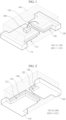
- FIG. 1 is a perspective view of a light emitting device according to an exemplary embodiment
- FIG. 2 is a bottom perspective view of the light emitting device of FIG. 1
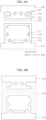
- FIG. 3a is a bottom view of a lead frame depicted in FIGS. 1 and 2
- FIG. 3b is a bottom view of the light emitting device of FIGS. 1 and 2 .
- a light emitting device includes a plurality of lead frame units 10, a light emitting diode chip 130 mounted on one of the lead frame units 10, and a molding unit 140 that is formed on a top surface of the lead frame units 1- to protect the light emitting diode chip 130.
- the lead frame units 10 are for mounting the light emitting diode chip 130 or connected to the light emitting diode chip 130 to apply external power to the light emitting diode chip 130.
- a separate supporting unit such as a separate insulation substrate for supporting the lead frame units 10 is not provided, but the lead frame unit 10 formed of metal functions as the substrate.
- the lead frame units 10 include first and second lead frames 110 that are spaced apart from each other at a predetermined interval. At this point, the first and second lead frames 110 and 120 may not be formed in a plate shape but in a convex shape.
- the first and second lead frames 110 and 120 are provided with fixing spaces formed through bodies of the first and second lead frames 110 and 120 in a vertical direction.
- molding resin for the molding unit 140 is filled in the fixing spaces 20 such that the molding resin applied on the top surfaces of the first and second lead frames 110 and 120 and the molding resin filled in the fixing spaces 20 can be monolithic. That is, the fixing spaces 20 functions to allow the molding unit 140 to be securely adhered to the top surfaces of the lead frame units 10.
- the fixing spaces include outer fixing holes 111 and 121 that are formed at a region where the first and second lead frames 110 and 120 face each other and a region surrounding opposite side edges of the respective first and second lead frames 110 and 120.
- the outer fixing holes 111 and 121 may be some or all of the above described regions.
- the fixing holes 111 and 121 are formed to be connected to each other at the facing region where the first and second lead frames 110 and 120 face each other and the regions adjacent to the facing regions.
- stepped portions 113 and 123 may be formed on sidewalls of the outer fixing holes 111 and 121 such that an area of a lower portion of each of the outer fixing holes 111 and 121 is greater than an upper portion of each of the outer fixing holes 111 and 121. Therefore, the molding unit 140 formed on the top surfaces of the first and second lead frames 110 and 120 extends to the outer fixing holes 111 and 121 and is hooked on the stepped portions 113 and 123. Therefore, the separation of the molding unit 140 from the first and second lead frames 110 and 120 can be physically prevented.
- a method for making the lower portion of the molding unit 140 formed in the outer fixing holes 111 and 121 have a greater area than the upper portion of the molding portion 140 is not limited to the above. That is, the method may be variously modified and the modified examples will be described later.
- the light emitting diode chip 130 is for emitting light by receiving the external power.
- the light emitting diode chip 130 may be selected among chips that emit light from an infrared band to a ultraviolet band.
- the light emitting diode chip 130 is mounted on the first lead frame 110 and electrically connected to the second lead frame 120 by a wire 150.
- the wire 150 may be formed of gold (Au) or aluminum (Al) through and connected to the second lead frame 120 through, for example, a wire connecting process.
- the molding unit 140 is for protecting the light emitting diode 130 and the wire 150 by enclosing the same.
- a method of forming the molding unit 140 and a shape of the molding unit 140 can be variously realized.
- the molding unit 140 may be formed through a transfer molding method where a mold having a cavity having a polygonal or hemispherical cavity and molding resin is filled in the cavity.
- the molding unit 140 is formed through a transfer molding method using a mold having a cavity that is designed to apply the molding resin on a portion of the top surfaces of the first and second lead frames 110 and 120 and fill the molding resin in the fixing holes 111 and 121.
- the molding unit 140 is integrally formed a portion of the top surfaces of the first and second lead frames 110 and 120, which includes a first region at which the light emitting diode chip 130 and the wire 150 are formed, a second region around the first region, and a third region defining the fixing space 20.
- the molding unit 140 may be formed of transparent silicon resin or epoxy resin that has a relatively high rigidity.
- the present invention is not limited to this. That is, other kinds of resin that is transparent to transmit light may be used in accordance with the use of the light emitting device.
- a variety of phosphors (not shown) may be mixed with the molding unit 140 to realize a variety of colors by changing a wavelength of the light emitted from the light emitting diode chip 130.
- FIG. 4 is a perspective view of a light emitting device according to another exemplary embodiment
- FIG. 5 is a bottom perspective view of the light emitting device of FIG. 4
- FIG. 6a is a bottom view of a lead frame depicted in FIGS. 4 and 5
- FIG. 6b is a bottom view of the light emitting device of FIGS. 4 and 5 .
- the light emitting device of this exemplary embodiment is almost identical to that of the foregoing embodiment of FIGS. 1 through 3b except that the fixing spaces 20 are modified.
- parts identical to those of the foregoing exemplary embodiment will not be described.
- the fixing space 20 further includes one or more inner fixing holes 115 and 125 formed through the bodies of the first and second lead frames 110 and 120 in the vertical direction. Sizes, shapes, and number of the inner fixing holes 115 and 125 are not specifically limited. Any things will be possible as far as the portions of the molding unit 140, which are filled and formed in the inner fixing holes 115 and 125 are monolithic with the portion of the molding unit 140, which is formed on the top surfaces of the first and second lead frames 110 and 120.
- the inner fixing holes 115 and 125 are formed in a variety of shapes such as a circular shape, an oval shape, and a rectangular shape.
- stepped portions 117 and 127 are formed on inner sidewalls of the inner fixing holes 115 and 125 such that an lower area is greater than an upper area. Accordingly, the molding unit 140 is hooked on the stepped portions 113, 117, 123, and 127 and thus the separation of the molding unit 140 from the first and second lead frames 110 and 120 can be prevented. are formed on inner walls
- the fixing spaces 20 include all of the outer fixing holes s11 and 121 and the inner fixing holes 115 and 125 as in this exemplary embodiment, it may be possible the fixing spaces 20 include only the inner fixing holes 115 and 125.
- FIGS. 7 to 9 are cross-sectional views illustrating modified examples of the light emitting device of the foregoing exemplary embodiments.
- FIGS. 7 to 9 are almost similar to the foregoing embodiments of FIGS. 1 through 6a except that a reflector 160 is further provided, the lead frame unit 10 is modified, and the fixing spaces 20 are modified.
- a reflector 160 is further provided, the lead frame unit 10 is modified, and the fixing spaces 20 are modified.
- a reflector 160 for collecting or scattering the light emitted from the light emitting diode chip 130 are formed on an edge of the top surfaces of the lead frame units 10. At this point, a reflecting surface is formed on an inner surface of the reflector 160 to direct the light emitted from the light emitting diode chip 130 in a desired direction.
- the reflector 160 may be formed of a transparent material to scatter the light generated from the light emitting diode chip 130 in a desired direction.
- the reflector 160 may be formed through the previously described transfer molding method.
- the molding unit 140 may be formed through not only the transfer molding method but also a dotting method.
- the lead frame units 10 include three lead frames spaced apart from each other.
- the lead frame units 10 may further include a third lead frame 170 disposed between the first and second lead frames 110 and 120 and the light emitting diode chip 130 is mounted on the third lead frame 170.
- a contacting surface between the light emitting diode chip 130 and the third lead frame 130 may be insulated.
- the light emitting diode chip 130 is electrically connected to the first and second lead frames 110 and 120 by respective wires 150a and 150b.
- outer fixing holes 111 and 121 and the inner fixing holes 115 and 125 are formed through the first and second lead frames 110 and 120 and the stepped portions 113, 117, 123, and 127 are formed on the sidewalls of the outer and inner fixing holes 111, 121, 115, and 125.
- outer and inner fixing holes 171 and 175 are formed through the third lead frame 170 and stepped portions 137 and 177 are formed on sidewalls of the outer and inner fixing holes 171 and 175. Accordingly, the adhesive force between the molding unit 140 and the lead frame units 10 can be improved.
- the reflector 160 may be formed on the fist and second lead frames 110 and 120.
- a shape of the fixing spaces is varied. That is, instead of forming the stepped portions 113, 117, 123, and 127 on the sidewalls of the outer and inner fixing holes 111, 121, 115, and 125 so that the lower area can be greater than the upper area, the inner sidewalls of the outer and inner fixing holes 111, 121, 115, and 125 are provided with inclined surfaces 118, 119, 128, and 129 such that the areas of the outer and inner fixing holes 111, 121, 115, and 125 gradually increase downward.
- the inclined surfaces are formed on all of the inner sidewalls of the fixing spaces 20, the present invention is not limited to this configuration. That is, the inclined surfaces may be formed only on some of the inner walls. Accordingly, the separation of the molding unit 140 can be prevented by portions of the molding unit 140 that are filled and formed in the outer and inner fixing holes 111, 121, 115, and 125.
- a phenomenon where a boundary surface between the lead frame and the molding unit is widened can be prevented by improving an adhering performance of the molding unit to the lead frame by forming the fixing space through the body of the lead frame in the vertical direction and integrally forming the molding unit on a top surface of the lead frame and in the fixing space of the lead frame.
- the separation of a portion of the molding unit, which is formed on the top surface of the lead frame, from the lead frame can be physically prevented by a portion of the molding unit, which is formed on the fixing space.
Applications Claiming Priority (4)
| Application Number | Priority Date | Filing Date | Title |
|---|---|---|---|
| KR1020080114624A KR100888236B1 (ko) | 2008-11-18 | 2008-11-18 | 발광 장치 |
| EP08021901.7A EP2187459B1 (de) | 2008-11-18 | 2008-12-17 | Lichtemittierende Vorrichtung |
| EP21198688.0A EP3951899B1 (de) | 2008-11-18 | 2008-12-17 | Lichtemittierende vorrichtung |
| EP18175319.5A EP3392920B3 (de) | 2008-11-18 | 2008-12-17 | Lichtemittierende vorrichtung |
Related Parent Applications (3)
| Application Number | Title | Priority Date | Filing Date |
|---|---|---|---|
| EP08021901.7A Division EP2187459B1 (de) | 2008-11-18 | 2008-12-17 | Lichtemittierende Vorrichtung |
| EP18175319.5A Division EP3392920B3 (de) | 2008-11-18 | 2008-12-17 | Lichtemittierende vorrichtung |
| EP21198688.0A Division EP3951899B1 (de) | 2008-11-18 | 2008-12-17 | Lichtemittierende vorrichtung |
Publications (2)
| Publication Number | Publication Date |
|---|---|
| EP4310928A2 true EP4310928A2 (de) | 2024-01-24 |
| EP4310928A3 EP4310928A3 (de) | 2024-02-21 |
Family
ID=40698097
Family Applications (4)
| Application Number | Title | Priority Date | Filing Date |
|---|---|---|---|
| EP23209902.8A Pending EP4310928A3 (de) | 2008-11-18 | 2008-12-17 | Lichtemittierende vorrichtung |
| EP21198688.0A Active EP3951899B1 (de) | 2008-11-18 | 2008-12-17 | Lichtemittierende vorrichtung |
| EP18175319.5A Active EP3392920B3 (de) | 2008-11-18 | 2008-12-17 | Lichtemittierende vorrichtung |
| EP08021901.7A Active EP2187459B1 (de) | 2008-11-18 | 2008-12-17 | Lichtemittierende Vorrichtung |
Family Applications After (3)
| Application Number | Title | Priority Date | Filing Date |
|---|---|---|---|
| EP21198688.0A Active EP3951899B1 (de) | 2008-11-18 | 2008-12-17 | Lichtemittierende vorrichtung |
| EP18175319.5A Active EP3392920B3 (de) | 2008-11-18 | 2008-12-17 | Lichtemittierende vorrichtung |
| EP08021901.7A Active EP2187459B1 (de) | 2008-11-18 | 2008-12-17 | Lichtemittierende Vorrichtung |
Country Status (8)
| Country | Link |
|---|---|
| US (7) | US7964943B2 (de) |
| EP (4) | EP4310928A3 (de) |
| JP (1) | JP5226498B2 (de) |
| KR (1) | KR100888236B1 (de) |
| ES (1) | ES2904839T3 (de) |
| LT (1) | LT3951899T (de) |
| PL (1) | PL3392920T3 (de) |
| SI (1) | SI3951899T1 (de) |
Families Citing this family (76)
| Publication number | Priority date | Publication date | Assignee | Title |
|---|---|---|---|---|
| KR100998233B1 (ko) * | 2007-12-03 | 2010-12-07 | 서울반도체 주식회사 | 슬림형 led 패키지 |
| CN101420007B (zh) * | 2008-10-23 | 2010-12-29 | 旭丽电子(广州)有限公司 | 一种led晶片的封装结构和封装方法 |
| DE102009012517A1 (de) | 2009-03-10 | 2010-09-16 | Osram Opto Semiconductors Gmbh | Optoelektronisches Halbleiterbauelement |
| JP2010238833A (ja) * | 2009-03-31 | 2010-10-21 | Panasonic Corp | 光半導体装置用パッケージおよび光半導体装置 |
| US8829685B2 (en) * | 2009-03-31 | 2014-09-09 | Semiconductor Components Industries, Llc | Circuit device having funnel shaped lead and method for manufacturing the same |
| US8120055B2 (en) * | 2009-04-20 | 2012-02-21 | Avago Technologies Ecbu Ip (Singapore) Pte. Ltd. | Light source |
| US9269875B2 (en) * | 2009-05-20 | 2016-02-23 | Intellectual Discovery Co., Ltd. | Light emitter |
| TW201128812A (en) | 2009-12-01 | 2011-08-16 | Lg Innotek Co Ltd | Light emitting device |
| KR101177896B1 (ko) * | 2010-03-02 | 2012-08-28 | 희성전자 주식회사 | 에스엠디 타입 엘이디 램프 |
| EP2365552A3 (de) * | 2010-03-09 | 2015-03-25 | LG Innotek Co., Ltd. | Lichtemittierendes Bauteil mit einem Anschlußträger der eine Einbuchtung aufweist. |
| TWI561770B (en) | 2010-04-30 | 2016-12-11 | Samsung Electronics Co Ltd | Light emitting device package, light source module, backlight unit, display apparatus, television set, and illumination apparatus |
| JP2012028744A (ja) * | 2010-06-22 | 2012-02-09 | Panasonic Corp | 半導体装置用パッケージおよびその製造方法ならびに半導体装置 |
| JP2012028743A (ja) * | 2010-06-22 | 2012-02-09 | Panasonic Corp | 半導体装置用パッケージおよびその製造方法ならびに半導体装置 |
| KR101689396B1 (ko) * | 2010-07-07 | 2016-12-23 | 서울반도체 주식회사 | 발광 소자 |
| JP5696441B2 (ja) * | 2010-09-03 | 2015-04-08 | 日亜化学工業株式会社 | 発光装置、発光装置の製造方法、及び発光装置用パッケージアレイ |
| TWM400099U (en) * | 2010-09-27 | 2011-03-11 | Silitek Electronic Guangzhou | Lead frame, package structure and lighting device thereof |
| KR101198860B1 (ko) | 2010-11-08 | 2012-11-07 | 주식회사 파워라이텍 | 리드프레임 및 이를 이용한 반도체 소자 패키지 |
| JP2012114311A (ja) * | 2010-11-26 | 2012-06-14 | Toshiba Corp | Ledモジュール |
| KR101675588B1 (ko) * | 2011-03-07 | 2016-11-11 | 엘지이노텍 주식회사 | 발광 소자 패키지 |
| KR101762174B1 (ko) * | 2011-03-25 | 2017-08-07 | 삼성전자 주식회사 | 발광소자 패키지 및 제조방법 |
| CN102760824B (zh) * | 2011-04-29 | 2016-06-08 | 展晶科技(深圳)有限公司 | 发光二极管封装结构 |
| KR101832306B1 (ko) | 2011-05-30 | 2018-02-26 | 엘지이노텍 주식회사 | 발광소자 패키지 |
| JP5706254B2 (ja) * | 2011-07-05 | 2015-04-22 | 株式会社東芝 | 半導体装置 |
| KR101865272B1 (ko) * | 2011-07-26 | 2018-06-07 | 삼성전자주식회사 | 발광소자 모듈 및 이의 제조방법 |
| KR101905535B1 (ko) * | 2011-11-16 | 2018-10-10 | 엘지이노텍 주식회사 | 발광 소자 패키지 및 이를 구비한 조명 장치 |
| KR20130096094A (ko) | 2012-02-21 | 2013-08-29 | 엘지이노텍 주식회사 | 발광소자 패키지, 발광 소자 패키지 제조방법 및 이를 구비한 조명 시스템 |
| CN103367598A (zh) * | 2012-03-29 | 2013-10-23 | 展晶科技(深圳)有限公司 | 发光二极管封装结构 |
| CN103367619B (zh) * | 2012-03-30 | 2015-12-02 | 光宝电子(广州)有限公司 | 金属支架结构及发光二极管结构 |
| DE102012211220A1 (de) * | 2012-06-28 | 2014-01-02 | Osram Opto Semiconductors Gmbh | Elektrisches Bauteil und Verfahren zum Herstellen von elektrischen Bauteilen |
| KR101936289B1 (ko) * | 2012-07-17 | 2019-01-08 | 엘지이노텍 주식회사 | 발광 소자 |
| JP6155584B2 (ja) * | 2012-09-19 | 2017-07-05 | 大日本印刷株式会社 | 光半導体装置用リードフレーム、樹脂付き光半導体装置用リードフレーム、リードフレームの多面付け体、樹脂付きリードフレームの多面付け体、光半導体装置、光半導体装置の多面付け体 |
| JP6019988B2 (ja) * | 2012-09-19 | 2016-11-02 | 大日本印刷株式会社 | 光半導体装置用リードフレーム、樹脂付き光半導体装置用リードフレーム、リードフレームの多面付け体、樹脂付きリードフレームの多面付け体、光半導体装置、光半導体装置の多面付け体 |
| KR102019498B1 (ko) * | 2012-10-11 | 2019-09-06 | 엘지이노텍 주식회사 | 발광 소자 및 조명 시스템 |
| TW201417343A (zh) * | 2012-10-22 | 2014-05-01 | Lextar Electronics Corp | 發光二極體封裝結構及大照明角度的發光二極體燈具 |
| CN103887398B (zh) * | 2012-12-22 | 2017-06-20 | 展晶科技(深圳)有限公司 | 发光二极管封装结构 |
| KR102029802B1 (ko) * | 2013-01-14 | 2019-10-08 | 엘지이노텍 주식회사 | 발광 소자 및 이를 구비한 조명 장치 |
| KR101974354B1 (ko) | 2013-02-14 | 2019-05-02 | 삼성전자주식회사 | 발광소자 패키지 및 그 제조 방법 |
| JP6167556B2 (ja) * | 2013-02-21 | 2017-07-26 | 大日本印刷株式会社 | リードフレーム、樹脂付きリードフレーム、リードフレームの多面付け体、樹脂付きリードフレームの多面付け体、光半導体装置、光半導体装置の多面付け体 |
| US9748164B2 (en) * | 2013-03-05 | 2017-08-29 | Nichia Corporation | Semiconductor device |
| JP6634117B2 (ja) | 2013-04-16 | 2020-01-22 | ローム株式会社 | 半導体装置 |
| JP6352009B2 (ja) | 2013-04-16 | 2018-07-04 | ローム株式会社 | 半導体装置 |
| KR102053287B1 (ko) * | 2013-04-29 | 2019-12-06 | 엘지이노텍 주식회사 | 발광 소자 및 이를 구비한 조명 시스템 |
| KR101655505B1 (ko) * | 2013-06-13 | 2016-09-07 | 엘지이노텍 주식회사 | 발광 소자 |
| KR101689397B1 (ko) * | 2013-06-28 | 2016-12-23 | 서울반도체 주식회사 | 발광 소자 |
| JP2015041722A (ja) * | 2013-08-23 | 2015-03-02 | 株式会社東芝 | 半導体発光装置 |
| TWI610465B (zh) * | 2013-10-07 | 2018-01-01 | 晶元光電股份有限公司 | 發光二極體組件及製作方法 |
| JP6214431B2 (ja) * | 2014-02-28 | 2017-10-18 | Shマテリアル株式会社 | Led用リードフレーム |
| JP5910653B2 (ja) | 2014-03-18 | 2016-04-27 | トヨタ自動車株式会社 | 放熱板付きリードフレーム、放熱板付きリードフレームの製造方法、半導体装置、および半導体装置の製造方法 |
| KR102161272B1 (ko) * | 2014-03-25 | 2020-09-29 | 엘지이노텍 주식회사 | 발광 소자 패키지 |
| JP6671117B2 (ja) * | 2014-07-08 | 2020-03-25 | エルジー イノテック カンパニー リミテッド | 発光素子パッケージ |
| KR102252156B1 (ko) * | 2014-07-08 | 2021-05-17 | 엘지이노텍 주식회사 | 발광 소자 패키지 |
| US11686436B2 (en) | 2014-09-28 | 2023-06-27 | Zhejiang Super Lighting Electric Appliance Co., Ltd | LED filament and light bulb using LED filament |
| US11525547B2 (en) | 2014-09-28 | 2022-12-13 | Zhejiang Super Lighting Electric Appliance Co., Ltd | LED light bulb with curved filament |
| US11690148B2 (en) | 2014-09-28 | 2023-06-27 | Zhejiang Super Lighting Electric Appliance Co., Ltd. | LED filament and LED light bulb |
| US11085591B2 (en) | 2014-09-28 | 2021-08-10 | Zhejiang Super Lighting Electric Appliance Co., Ltd | LED light bulb with curved filament |
| US11073248B2 (en) | 2014-09-28 | 2021-07-27 | Zhejiang Super Lighting Electric Appliance Co., Ltd. | LED bulb lamp |
| US11543083B2 (en) | 2014-09-28 | 2023-01-03 | Zhejiang Super Lighting Electric Appliance Co., Ltd | LED filament and LED light bulb |
| US11421827B2 (en) | 2015-06-19 | 2022-08-23 | Zhejiang Super Lighting Electric Appliance Co., Ltd | LED filament and LED light bulb |
| CN104269488A (zh) * | 2014-10-21 | 2015-01-07 | 江苏稳润光电有限公司 | 一种高可靠性led封装结构及方法 |
| USD786203S1 (en) * | 2015-02-24 | 2017-05-09 | Nichia Corporation | Light emitting diode |
| KR101896692B1 (ko) * | 2015-03-26 | 2018-09-07 | 엘지이노텍 주식회사 | 발광 소자 |
| JP6751554B2 (ja) * | 2015-08-20 | 2020-09-09 | 株式会社カネカ | 発光素子実装用樹脂成形体、表面実装型発光装置、及び発光素子実装用樹脂成形体に用いるリードフレーム |
| KR102413302B1 (ko) * | 2015-11-24 | 2022-06-27 | 쑤저우 레킨 세미컨덕터 컴퍼니 리미티드 | 발광 소자 패키지 및 이를 포함하는 차량용 조명 장치 |
| US10461233B2 (en) | 2015-11-27 | 2019-10-29 | Lg Innotek Co., Ltd. | Light emitting device package and lighting device |
| KR102528014B1 (ko) * | 2015-11-27 | 2023-05-10 | 쑤저우 레킨 세미컨덕터 컴퍼니 리미티드 | 발광소자 패키지 및 조명 장치 |
| KR102486034B1 (ko) * | 2015-11-27 | 2023-01-11 | 쑤저우 레킨 세미컨덕터 컴퍼니 리미티드 | 발광소자 패키지 및 조명 장치 |
| CN105679770B (zh) * | 2016-01-28 | 2019-02-26 | 京东方科技集团股份有限公司 | 阵列基板及其制造方法 |
| JP6790416B2 (ja) | 2016-03-31 | 2020-11-25 | 日亜化学工業株式会社 | 発光装置 |
| US10153412B2 (en) * | 2016-08-11 | 2018-12-11 | Institute of Nuclear Energy Research, Atomic Energy Council, Executive Yuan, R.O.C. | Package structure for ultraviolet light-emitting diode |
| JP2016225655A (ja) * | 2016-09-21 | 2016-12-28 | 大日本印刷株式会社 | 光半導体装置用リードフレーム、樹脂付き光半導体装置用リードフレーム、リードフレームの多面付け体、樹脂付きリードフレームの多面付け体、光半導体装置、光半導体装置の多面付け体 |
| US11677059B2 (en) * | 2017-04-26 | 2023-06-13 | Samsung Electronics Co., Ltd. | Light-emitting device package including a lead frame |
| CN107086265A (zh) * | 2017-06-02 | 2017-08-22 | 厦门立达信绿色照明集团有限公司 | 发光二极管模组跟灯具装置 |
| JP6637003B2 (ja) * | 2017-09-08 | 2020-01-29 | サンコール株式会社 | バスバーアッセンブリ |
| US20190267525A1 (en) | 2018-02-26 | 2019-08-29 | Semicon Light Co., Ltd. | Semiconductor Light Emitting Devices And Method Of Manufacturing The Same |
| JP6975916B2 (ja) * | 2018-08-09 | 2021-12-01 | 日亜化学工業株式会社 | 発光装置 |
| CN109285935A (zh) * | 2018-11-07 | 2019-01-29 | 东莞市亿晶源光电科技有限公司 | 一种通体发光led灯珠及灯串 |
Family Cites Families (28)
| Publication number | Priority date | Publication date | Assignee | Title |
|---|---|---|---|---|
| CN1219320C (zh) * | 1998-05-20 | 2005-09-14 | 罗姆股份有限公司 | 半导体器件 |
| US6335548B1 (en) * | 1999-03-15 | 2002-01-01 | Gentex Corporation | Semiconductor radiation emitter package |
| JP2001077278A (ja) * | 1999-10-15 | 2001-03-23 | Amkor Technology Korea Inc | 半導体パッケージと、このためのリードフレーム及び、半導体パッケージの製造方法とそのモールド |
| US20020066905A1 (en) * | 2000-06-20 | 2002-06-06 | Bily Wang | Wing-shaped surface mount package for light emitting diodes |
| JP4889169B2 (ja) * | 2001-08-30 | 2012-03-07 | ローム株式会社 | 半導体装置およびその製造方法 |
| TW546799B (en) * | 2002-06-26 | 2003-08-11 | Lingsen Precision Ind Ltd | Packaged formation method of LED and product structure |
| US7692206B2 (en) * | 2002-12-06 | 2010-04-06 | Cree, Inc. | Composite leadframe LED package and method of making the same |
| JP2006313943A (ja) * | 2003-02-18 | 2006-11-16 | Sharp Corp | 半導体発光装置、その製造方法および電子撮像装置 |
| KR100757615B1 (ko) * | 2003-07-17 | 2007-09-10 | 마츠시타 덴끼 산교 가부시키가이샤 | 전계 효과형 트랜지스터 및 그 제조 방법 |
| WO2005036507A2 (en) * | 2003-10-08 | 2005-04-21 | M.H. Segan Limited Partnership | Foldable modular light array |
| JP2005197329A (ja) * | 2004-01-05 | 2005-07-21 | Stanley Electric Co Ltd | 表面実装型半導体装置及びそのリードフレーム構造 |
| JP4359195B2 (ja) * | 2004-06-11 | 2009-11-04 | 株式会社東芝 | 半導体発光装置及びその製造方法並びに半導体発光ユニット |
| US7476913B2 (en) * | 2004-08-10 | 2009-01-13 | Renesas Technology Corp. | Light emitting device having a mirror portion |
| JP4468115B2 (ja) * | 2004-08-30 | 2010-05-26 | 株式会社ルネサステクノロジ | 半導体装置 |
| KR100587020B1 (ko) * | 2004-09-01 | 2006-06-08 | 삼성전기주식회사 | 고출력 발광 다이오드용 패키지 |
| TWI277223B (en) * | 2004-11-03 | 2007-03-21 | Chen-Lun Hsingchen | A low thermal resistance LED package |
| WO2006065007A1 (en) * | 2004-12-16 | 2006-06-22 | Seoul Semiconductor Co., Ltd. | Leadframe having a heat sink supporting ring, fabricating method of a light emitting diodepackage using the same and light emitting diodepackage fabbricated by the method |
| JP4711715B2 (ja) * | 2005-03-30 | 2011-06-29 | 株式会社東芝 | 半導体発光装置及び半導体発光ユニット |
| JP2007027433A (ja) * | 2005-07-15 | 2007-02-01 | Mitsubishi Cable Ind Ltd | 発光装置 |
| US7537374B2 (en) * | 2005-08-27 | 2009-05-26 | 3M Innovative Properties Company | Edge-lit backlight having light recycling cavity with concave transflector |
| JP2007134376A (ja) * | 2005-11-08 | 2007-05-31 | Akita Denshi Systems:Kk | 発光ダイオード装置及びその製造方法 |
| JP2007157296A (ja) * | 2005-12-08 | 2007-06-21 | Toshiba Corp | 半導体記憶装置 |
| KR100735325B1 (ko) * | 2006-04-17 | 2007-07-04 | 삼성전기주식회사 | 발광다이오드 패키지 및 그 제조방법 |
| US20070290220A1 (en) * | 2006-06-20 | 2007-12-20 | Bily Wang | Package for a light emitting diode and a process for fabricating the same |
| US8044418B2 (en) * | 2006-07-13 | 2011-10-25 | Cree, Inc. | Leadframe-based packages for solid state light emitting devices |
| EP2109157B1 (de) * | 2006-12-28 | 2018-11-28 | Nichia Corporation | Leuchtbauelement und verfahren zu seiner herstellung |
| WO2008153043A1 (ja) * | 2007-06-14 | 2008-12-18 | Rohm Co., Ltd. | 半導体発光装置 |
| KR100880638B1 (ko) * | 2007-07-06 | 2009-01-30 | 엘지전자 주식회사 | 발광 소자 패키지 |
-
2008
- 2008-11-18 KR KR1020080114624A patent/KR100888236B1/ko active IP Right Grant
- 2008-12-17 LT LTEP21198688.0T patent/LT3951899T/lt unknown
- 2008-12-17 EP EP23209902.8A patent/EP4310928A3/de active Pending
- 2008-12-17 SI SI200832218T patent/SI3951899T1/sl unknown
- 2008-12-17 EP EP21198688.0A patent/EP3951899B1/de active Active
- 2008-12-17 PL PL18175319T patent/PL3392920T3/pl unknown
- 2008-12-17 ES ES18175319T patent/ES2904839T3/es active Active
- 2008-12-17 EP EP18175319.5A patent/EP3392920B3/de active Active
- 2008-12-17 EP EP08021901.7A patent/EP2187459B1/de active Active
- 2008-12-18 JP JP2008322737A patent/JP5226498B2/ja active Active
- 2008-12-19 US US12/339,665 patent/US7964943B2/en active Active
-
2011
- 2011-05-11 US US13/105,549 patent/US8558270B2/en active Active
-
2013
- 2013-06-19 US US13/921,556 patent/US8829552B2/en active Active
-
2014
- 2014-09-08 US US14/480,042 patent/US9147821B2/en active Active
-
2015
- 2015-02-27 US US14/633,856 patent/US9203006B2/en active Active
- 2015-11-18 US US14/944,881 patent/US9461225B2/en active Active
-
2016
- 2016-08-30 US US15/252,174 patent/US10134967B2/en active Active
Also Published As
| Publication number | Publication date |
|---|---|
| US20110210366A1 (en) | 2011-09-01 |
| SI3951899T1 (sl) | 2024-04-30 |
| US20100123156A1 (en) | 2010-05-20 |
| JP5226498B2 (ja) | 2013-07-03 |
| EP3392920A1 (de) | 2018-10-24 |
| KR100888236B1 (ko) | 2009-03-12 |
| US20140374788A1 (en) | 2014-12-25 |
| EP2187459B1 (de) | 2018-08-22 |
| EP3392920B1 (de) | 2021-10-27 |
| US7964943B2 (en) | 2011-06-21 |
| EP2187459A2 (de) | 2010-05-19 |
| US20160372647A1 (en) | 2016-12-22 |
| EP4310928A3 (de) | 2024-02-21 |
| US8558270B2 (en) | 2013-10-15 |
| PL3392920T3 (pl) | 2022-02-21 |
| US9461225B2 (en) | 2016-10-04 |
| ES2904839T3 (es) | 2022-04-06 |
| US9147821B2 (en) | 2015-09-29 |
| US20160072032A1 (en) | 2016-03-10 |
| US10134967B2 (en) | 2018-11-20 |
| US9203006B2 (en) | 2015-12-01 |
| EP2187459A3 (de) | 2012-08-08 |
| EP3392920B3 (de) | 2022-04-20 |
| US20130277705A1 (en) | 2013-10-24 |
| US8829552B2 (en) | 2014-09-09 |
| US20150171300A1 (en) | 2015-06-18 |
| LT3951899T (lt) | 2024-03-12 |
| JP2010123908A (ja) | 2010-06-03 |
| EP3951899B1 (de) | 2023-12-06 |
| EP3951899A1 (de) | 2022-02-09 |
Similar Documents
| Publication | Publication Date | Title |
|---|---|---|
| US10134967B2 (en) | Light emitting device | |
| EP2696377B1 (de) | Lichtemittierende Vorrichtung | |
| US7514724B2 (en) | Solid state light source having a variable number of dies | |
| US8338851B2 (en) | Multi-layer LED array engine | |
| US20150003038A1 (en) | Led assembly with omnidirectional light field | |
| US20090001405A1 (en) | Light emitting device package and manufacturing method thereof | |
| US20100012967A1 (en) | Semiconductor light emitting device package | |
| KR101006357B1 (ko) | 멀티칩 엘이디 패키지 | |
| KR20080030584A (ko) | 반도체 발광 장치 패키지 구조 | |
| US20120025258A1 (en) | Light emitting diode package and light emitting diode module | |
| KR20110099513A (ko) | 조명 장치 | |
| US9822959B2 (en) | Light emitting device | |
| KR20090068399A (ko) | 복수의 패키지를 모듈화한 리드프레임을 이용한발광다이오드 모듈 | |
| KR20120001189A (ko) | 발광 다이오드 패키지 | |
| US8581278B2 (en) | Light-emitting diode packaging structure | |
| KR100839122B1 (ko) | 측면 발광형 led 램프 및 그 제조방법과, 그 led램프를 포함하는 발광장치 | |
| JP2011090972A (ja) | 発光装置及び照明装置 | |
| TWI291254B (en) | LED assembly structure | |
| KR20090032864A (ko) | 렌즈를 갖는 발광 다이오드 패키지 | |
| KR20150032112A (ko) | 조명장치 |
Legal Events
| Date | Code | Title | Description |
|---|---|---|---|
| PUAI | Public reference made under article 153(3) epc to a published international application that has entered the european phase |
Free format text: ORIGINAL CODE: 0009012 |
|
| STAA | Information on the status of an ep patent application or granted ep patent |
Free format text: STATUS: REQUEST FOR EXAMINATION WAS MADE |
|
| REG | Reference to a national code |
Ref country code: DE Ref legal event code: R079 Free format text: PREVIOUS MAIN CLASS: H01L0033540000 Ipc: H01L0033620000 |
|
| PUAL | Search report despatched |
Free format text: ORIGINAL CODE: 0009013 |
|
| 17P | Request for examination filed |
Effective date: 20231213 |
|
| AC | Divisional application: reference to earlier application |
Ref document number: 2187459 Country of ref document: EP Kind code of ref document: P Ref document number: 3392920 Country of ref document: EP Kind code of ref document: P Ref document number: 3951899 Country of ref document: EP Kind code of ref document: P |
|
| AK | Designated contracting states |
Kind code of ref document: A2 Designated state(s): AT BE BG CH CY CZ DE DK EE ES FI FR GB GR HR HU IE IS IT LI LT LU LV MC MT NL NO PL PT RO SE SI SK TR |
|
| AK | Designated contracting states |
Kind code of ref document: A3 Designated state(s): AT BE BG CH CY CZ DE DK EE ES FI FR GB GR HR HU IE IS IT LI LT LU LV MC MT NL NO PL PT RO SE SI SK TR |
|
| RIC1 | Information provided on ipc code assigned before grant |
Ipc: H01L 33/60 20100101ALN20240115BHEP Ipc: H01L 33/52 20100101ALN20240115BHEP Ipc: H01L 33/48 20100101ALN20240115BHEP Ipc: H01L 33/54 20100101ALI20240115BHEP Ipc: H01L 33/62 20100101AFI20240115BHEP |