EP4309902A1 - Kartusche - Google Patents
Kartusche Download PDFInfo
- Publication number
- EP4309902A1 EP4309902A1 EP22771233.8A EP22771233A EP4309902A1 EP 4309902 A1 EP4309902 A1 EP 4309902A1 EP 22771233 A EP22771233 A EP 22771233A EP 4309902 A1 EP4309902 A1 EP 4309902A1
- Authority
- EP
- European Patent Office
- Prior art keywords
- cartridge
- operation surface
- section
- attachment
- gravity
- Prior art date
- Legal status (The legal status is an assumption and is not a legal conclusion. Google has not performed a legal analysis and makes no representation as to the accuracy of the status listed.)
- Pending
Links
Images





Classifications
-
- B—PERFORMING OPERATIONS; TRANSPORTING
- B41—PRINTING; LINING MACHINES; TYPEWRITERS; STAMPS
- B41J—TYPEWRITERS; SELECTIVE PRINTING MECHANISMS, i.e. MECHANISMS PRINTING OTHERWISE THAN FROM A FORME; CORRECTION OF TYPOGRAPHICAL ERRORS
- B41J2/00—Typewriters or selective printing mechanisms characterised by the printing or marking process for which they are designed
- B41J2/005—Typewriters or selective printing mechanisms characterised by the printing or marking process for which they are designed characterised by bringing liquid or particles selectively into contact with a printing material
- B41J2/01—Ink jet
- B41J2/17—Ink jet characterised by ink handling
- B41J2/175—Ink supply systems ; Circuit parts therefor
- B41J2/17503—Ink cartridges
- B41J2/17553—Outer structure
-
- B—PERFORMING OPERATIONS; TRANSPORTING
- B41—PRINTING; LINING MACHINES; TYPEWRITERS; STAMPS
- B41J—TYPEWRITERS; SELECTIVE PRINTING MECHANISMS, i.e. MECHANISMS PRINTING OTHERWISE THAN FROM A FORME; CORRECTION OF TYPOGRAPHICAL ERRORS
- B41J2/00—Typewriters or selective printing mechanisms characterised by the printing or marking process for which they are designed
- B41J2/005—Typewriters or selective printing mechanisms characterised by the printing or marking process for which they are designed characterised by bringing liquid or particles selectively into contact with a printing material
- B41J2/01—Ink jet
- B41J2/17—Ink jet characterised by ink handling
- B41J2/175—Ink supply systems ; Circuit parts therefor
- B41J2/17503—Ink cartridges
-
- B—PERFORMING OPERATIONS; TRANSPORTING
- B41—PRINTING; LINING MACHINES; TYPEWRITERS; STAMPS
- B41J—TYPEWRITERS; SELECTIVE PRINTING MECHANISMS, i.e. MECHANISMS PRINTING OTHERWISE THAN FROM A FORME; CORRECTION OF TYPOGRAPHICAL ERRORS
- B41J2/00—Typewriters or selective printing mechanisms characterised by the printing or marking process for which they are designed
- B41J2/005—Typewriters or selective printing mechanisms characterised by the printing or marking process for which they are designed characterised by bringing liquid or particles selectively into contact with a printing material
- B41J2/01—Ink jet
- B41J2/17—Ink jet characterised by ink handling
- B41J2/175—Ink supply systems ; Circuit parts therefor
- B41J2/17503—Ink cartridges
- B41J2/1752—Mounting within the printer
Definitions
- the present disclosure relates to a technique of a cartridge.
- Patent Literature 1 A technique, in the related art, in which a cartridge is moved in a horizontal attachment direction to attach the cartridge to a cartridge attachment section of a printing apparatus is known (Patent Literature 1).
- a user pushes, in an attachment direction, a back surface of a cartridge on a front side and thereby applies a load to the cartridge to move the cartridge in the attachment direction.
- a load is applied to the cartridge to displace the cartridge in a plurality of directions, the applied load is distributed, which may degrade operability of the attachment process.
- the cartridge has a larger outer shape, operability of the process of attaching or detaching the cartridge to or from the printing apparatus may be degraded.
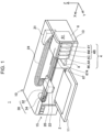
- Fig. 1 is a perspective view illustrating a configuration of a printing system 1 as an embodiment of the disclosure.
- the XYZ axes which are three spatial axes orthogonal to each other, are indicated in Fig. 1 .
- Directions indicated by the arrows of the X-axis, the Y-axis, and the Z-axis indicate positive directions extending along the X-axis, the Y-axis, and the Z-axis, respectively.
- the positive directions extending along the X-axis, the Y-axis, and the Z-axis are referred to as the +X direction, the +Y direction, and the +Z direction, respectively.
- Directions opposite to the directions indicated by the arrows of the X-axis, the Y-axis, and the Z-axis are negative directions extending along the X-axis, the Y-axis, and the Z-axis, respectively.
- the negative directions extending along the X-axis, the Y-axis, and the Z-axis are referred to as the -X direction, the -Y direction, and the -Z direction, respectively.
- Directions that extend along the X-axis, the Y-axis, and the Z-axis regardless of whether being positive or negative are referred to as the X direction, the Y direction, and the Z direction, respectively. The same is applicable to the drawings and description below.
- the printing system 1 includes a printing apparatus 10 and a cartridge 4 that supplies ink, which is a liquid, to the printing apparatus 10.
- the printing apparatus 10 of the present embodiment is an ink jet printer that ejects the ink as liquid from an ejecting head 22.
- the printing apparatus 10 is a large-format printer that performs printing on large sheets (for example, A2- to A0-sized sheets), such as posters.
- the printing apparatus 10 includes a cartridge attachment section 6, a control section 31, a carriage 20, the ejecting head 22, and a driving mechanism 30.
- the printing apparatus 10 includes an operation button 15 used by a user to operate the printing apparatus 10.
- the cartridge attachment section 6 includes a first apparatus wall 67 positioned on the +Y direction side.
- the first apparatus wall 67 includes an insertion/removal opening 674 serving as an entrance/exit of an accommodating chamber 61 for the cartridge 4.
- the cartridge 4 is accommodated in or removed from the accommodating chamber 61 of the cartridge attachment section 6 via the insertion/removal opening 674.
- a plurality of cartridges 4 are each detachably attached to the cartridge attachment section 6.
- four types of cartridges 4 which correspond to ink of four colors of black, yellow, magenta, and cyan, that is, a total of four cartridges 4, are attached to the cartridge attachment section 6.
- the cartridge 4 that stores black ink is referred to as a cartridge 4K
- the cartridge 4 that stores yellow ink is referred to as a cartridge 4Y
- the cartridge 4 that stores magenta ink is referred to as a cartridge 4M
- the cartridge 4 that stores cyan ink is referred to as a cartridge 4C.
- the cartridge 4K is configured to be able to store more liquid than the cartridges 4C, 4M, and 4Y. Accordingly, the cartridge 4K is also referred to as a first-type cartridge 4A, and each of the cartridges 4C, 4M, and 4Y is also referred to as a second-type cartridge 4B.
- the printing apparatus 10 includes a cover for replacement 13 on the front surface on the +Y direction side.
- the cover for replacement 13 is configured to be openable/closable. Opening the cover for replacement 13 exposes the opening of the cartridge attachment section 6 and enables the cartridge 4 to be attached/detached.
- ink is able to be supplied to the ejecting head 22, which is provided in the carriage 20, via a tube 24 serving as a liquid flowing tube.
- the ink is supplied to the ejecting head 22 from the cartridge 4 by using a water head difference.
- the water head difference between a liquid level of the ink in the cartridge attachment section 6 and the ejecting head 22 causes the ink to be supplied to the ejecting head 22.
- the ink may be supplied to the ejecting head 22 when the ink in the cartridge 4 is sucked by a non-illustrated pump mechanism of the printing apparatus 10.
- the tube 24 is provided for each type of ink.
- the attachment completed state a state in which the cartridge 4 is attached to the cartridge attachment section 6 and in which the ink as liquid is able to be supplied to the printing apparatus 10.
- Nozzles are provided in the ejecting head 22 for each type of ink.
- the ejecting head 22 ejects ink from the nozzles onto a printing sheet 2 and prints data such as characters or an image.
- the printing apparatus 10 of the present embodiment is a printer of a so-called "off-carriage type", in which the cartridge attachment section 6 does not move in accordance with movement of the carriage 20.
- the technique of the disclosure is also applicable to a printer of a so-called “on-carriage type", in which the cartridge attachment section 6 is provided in the carriage 20 and in which the cartridge attachment section 6 moves together with the carriage 20.
- the control section 31 controls the respective sections of the printing apparatus 10 and transmits or receives a signal to or from the cartridge 4.
- the carriage 20 causes the ejecting head 22 to move relative to the printing sheet 2.
- the driving mechanism 30 reciprocates the carriage 20 in accordance with a control signal from the control section 31.
- the driving mechanism 30 includes a timing belt 32 and a driving motor 34. Power of the driving motor 34 is transferred to the carriage 20 via the timing belt 32, and the carriage 20 is thereby reciprocated in a main scanning direction, which is the X direction.
- the printing apparatus 10 includes a transporting mechanism that moves the printing sheet 2 in a sub-scanning direction, which is the +Y direction. When printing is performed, the transporting mechanism moves the printing sheet 2 in the sub-scanning direction, and the printing sheet 2 on which printing is completed is output onto a front cover 11.
- a region called a home position is provided at a position to which the carriage 20 is moved in the main scanning direction and which is outside a printing region, and a maintenance mechanism that performs maintenance to ensure normal printing is mounted at the home position.
- the maintenance mechanism is constituted by a cap member 8 that is pressed against a surface on which the nozzles are formed on the bottom surface side of the ejecting head 22 and that forms a closed space so as to enclose the nozzles, a non-illustrated raising/lowering mechanism that raises/lowers the cap member 8 so as to press the cap member 8 against the nozzle surface of the ejecting head 22, a non-illustrated suction pump that introduces negative pressure into the enclosed space where the cap member 8 is formed by being pressed against the nozzle surface of the ejecting head 22, and the like.
- an axis extending in the sub-scanning direction in which the printing sheet 2 is transported is the Y-axis
- an axis extending in a downward direction in the direction of gravity is the Z-axis
- an axis extending in a direction in which the carriage 20 moves is the X-axis.
- "use state of the printing system 1" denotes a state in which the printing system 1 is installed on a horizontal surface.
- the sub-scanning direction is the +Y direction
- a direction opposite thereto is the -Y direction
- a downward direction in the direction of gravity is the -Z direction
- an upward direction against the direction of gravity is the +Z direction.
- the X direction and the Y direction extend in the horizontal direction.
- a direction from the right to the left is the +X direction
- a direction opposite thereto is the -X direction.
- an inserting direction in which the cartridge 4 is inserted into the cartridge attachment section 6 for attachment is the -Y direction
- a direction in which the cartridge 4 is detached from the cartridge attachment section 6 is the +Y direction.
- the -Y direction side is also referred to as a back side
- the +Y direction side is also referred to as a front side.
- an arrangement direction of the plurality of cartridges 4 extends in the X direction.
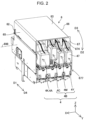
- Fig. 2 is a view for explaining the cartridge attachment section 6 and the cartridge 4.
- Fig. 2 illustrates the attachment completed state in which attachment of the cartridges 4K, 4M, and 4Y to the cartridge attachment section 6 is completed.
- Fig. 2 illustrates an insertion completed state in which insertion of the cartridge 4C into the cartridge attachment section 6 is completed.
- the cartridge 4 is moved in an inserting direction D1 extending in the horizontal direction to be inserted into the cartridge attachment section 6 at a predetermined position of the cartridge attachment section 6 and is then rotationally moved in a rotational-attachment direction D2, which has a component in the downward direction in the direction of gravity, with the back side of the cartridge attachment section 6 in the inserting direction D1 as a rotation fulcrum 698, thereby completing attachment of the cartridge 4 to the cartridge attachment section 6.
- the attachment process includes a terminal coupling process and a supply section coupling process performed after the terminal coupling process.
- the terminal coupling process is a process in which the cartridge 4 is moved in the inserting direction D1 extending in the horizontal direction via the insertion/removal opening 674 of the first apparatus wall 67 and inserted into the accommodating chamber 61 of the cartridge attachment section 6 such that the cartridge 4 is inserted into the cartridge attachment section 6 at a predetermined position.
- the predetermined position is a position at which contact of a cartridge-side terminal, which will be described below, of the cartridge 4 and an apparatus-side terminal, which will be described below, of the cartridge attachment section 6 is completed.
- the supply section coupling process is a process in which a liquid introducing section, which will be described below, of the cartridge attachment section 6 and a liquid supply section, which will be described below, of the cartridge 4 are coupled to each other in a state in which the apparatus-side terminal and the cartridge-side terminal are kept in contact with each other.
- the liquid introducing section and the liquid supply section are coupled to each other by rotationally moving a first operation surface 47 side of the cartridge 4 in the rotational-attachment direction D2, which is indicated by an arrow, about the rotation fulcrum 698 of the cartridge attachment section 6.
- an engagement forming body provided on the first apparatus wall 67 side of the cartridge attachment section 6 engages the cartridge 4, and the cartridge 4 thereby retains the attachment completed state.
- the user raises the first operation surface 47 side of the cartridge 4 to thereby rotationally move the rear end 47 side in a coupling terminating direction D3, which is opposite to the rotational-attachment direction D2, with the rotation fulcrum 698 as a fulcrum.
- the rotational movement terminates the engagement performed by the engagement forming body.
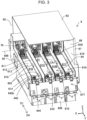
- Fig. 3 is a perspective view of the cartridge attachment section 6.
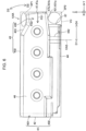
- Fig. 4 is a view of the cartridge attachment section 6 viewed from the +Z direction side. In Figs. 3 and 4 , for ease of understanding, illustration of the configuration of the cartridge attachment section 6 is partially omitted.
- the X direction, the Y direction, and the Z direction are also referred to as a width direction, a depth direction, and a height direction, respectively. In the following description, unless otherwise stated regarding state, each component will be described on the assumption that the cartridge attachment section 6 is in an initial arrangement state in which the cartridge 4 is not attached to the cartridge attachment section 6.
- the cartridge attachment section 6 forms the accommodating chamber 61 that accommodates the cartridge 4.
- the accommodating chamber 61 has a substantially rectangular parallelepiped shape.
- shapes of slots 61C, 61M, 61Y, and 61K which are portions for accommodating the cartridges 4C, 4M, 4Y, and 4K, respectively, substantially correspond to outer shapes of the cartridges 4C, 4M, 4Y, and 4K, respectively.
- the dimension of the cartridge 4K in the X direction is greater than that of each of the other cartridges 4C, 4M, and 4Y such that the amount of liquid to be stored in the cartridge 4K is increased.
- the width of the slot 61K is greater than the width of each of the other slots 61C, 61M, and 61Y in the present embodiment.
- the cartridge attachment section 6 includes six apparatus walls 62, 63, 64, 65, 66, and 67 that form the accommodating chamber 61.
- wall conceptually includes a structure constituted by multiple walls in addition to a structure constituted by a single wall.
- the first apparatus wall 67 forms the insertion/removal opening 674 through which the cartridge 4 is inserted into or removed from the accommodating chamber 61.
- a second apparatus wall 62 forms a wall of the accommodating chamber 61 on the -Y direction side.
- the second apparatus wall 62 faces the first apparatus wall 67 in the Y direction.
- the second apparatus wall 62 is substantially vertical in a use state of the printing apparatus 10.
- An apparatus top wall 63 forms a wall of the accommodating chamber 61 on the +Z direction side.
- An apparatus bottom wall 64 faces the apparatus top wall 63 in the Z direction and forms a wall of the accommodating chamber 61 on the -Z direction side.
- the apparatus bottom wall 64 is formed of a supporting member 610.
- the apparatus bottom wall 64 includes a plurality of apparatus openings 614. In the present embodiment, four apparatus openings 614 are formed so as to correspond to the slots 61C, 61M, 61Y, and 61K.
- the apparatus top wall 63 and the apparatus bottom wall 64 intersect the second apparatus wall 62 and the first apparatus wall 67.
- cross and intersect denote any of the following states: (i) a state in which two components intersect each other and actually cross each other; (ii) a state in which, when one of two components is extended, one component crosses the other component; and (iii) a state in which, when two components are extended, both components cross each other.
- a first apparatus side wall 65 forms a wall of the accommodating chamber 61 on the +X direction side.
- a second apparatus side wall 66 faces the first apparatus side wall 65 in the X direction and forms a wall of the accommodating chamber 61 on the -X direction side.
- the first apparatus side wall 65 and the second apparatus side wall 66 intersect the second apparatus wall 62, the first apparatus wall 67, the apparatus top wall 63, and the apparatus bottom wall 64.
- the cartridge attachment section 6 further includes the supporting member 610, a liquid introducing section 642, an apparatus-side supply section positioning section 644, an apparatus guiding section 602, and an engagement forming body 677.
- a plurality of supporting members 610 are provided so as to correspond to the number of cartridges 4 to be attached. In the present embodiment, four supporting members 610 are provided.
- the supporting member 610 forms the apparatus bottom wall 64 of the accommodating chamber 61 on the downward direction side in the direction of gravity.
- the supporting member 610 supports the cartridge 4 from the -Z direction side, which is the downward direction side in the direction of gravity.
- the supporting member 610 is a member extending in the Y direction.
- the supporting member 610 has a recessed shape.
- the supporting member 610 includes a main wall 613 forming the apparatus bottom wall 64, a first supporting side wall 611, and a second supporting side wall 612.
- the main wall 613 forms a recessed bottom portion positioned on the downward direction side in the direction of gravity.
- An apparatus opening 614 is formed in an end of the main wall 613 on the first apparatus wall 67 side. The apparatus opening 614 passes through the main wall 613 in the thickness direction of the main wall 613.
- the first supporting side wall 611 stands upright in the +Z direction, which is the upward direction against the direction of gravity, from an end of the main wall 613 on the +X direction side.
- the second supporting side wall 612 stands upright in the +Z direction from an end of the main wall 613 on the -X direction side.
- the first supporting side wall 611 and the second supporting side wall 612 face each other in the X direction.
- the apparatus guiding section 602 guides the cartridge 4 in the inserting direction D1 or the detaching direction D4.
- the apparatus guiding section 602 is provided for each of the supporting members 610.
- the apparatus guiding section 602 is provided in each of the first supporting side wall 611 and the second supporting side wall 612.
- the apparatus guiding section 602 is a protrusion provided in each of the first supporting side wall 611 and the second supporting side wall 612.
- a first apparatus guiding section 602a provided in the first supporting side wall 611 is a protrusion protruding from the first supporting side wall 611 toward the second supporting side wall 612.
- the first apparatus guiding section 602a extends in the Y direction.
- a plurality of first apparatus guiding sections 602a are arranged with a gap therebetween in the Y direction.
- a second apparatus guiding section 602b provided in the second supporting side wall 612 is a protrusion protruding from the second supporting side wall 612 toward the first supporting side wall 611.
- the second apparatus guiding section 602b extends in the Y direction.
- a plurality of second apparatus guiding sections 602b are arranged with a gap therebetween in the Y direction.
- the liquid introducing section 642 receives the liquid of the cartridge 4.
- the liquid introducing section 642 has a central axis CA1.
- the central axis CA1 is inclined 4° in the +Y direction with respect to the Z direction.
- the liquid introducing section 642 is positioned not in the accommodating chamber 61 but on the -Z direction side with respect to the accommodating chamber 61. That is, the liquid introducing section 642 is positioned opposite the supporting member 610 with the accommodating chamber 61 therebetween.
- the supporting member 610 When the supporting member 610 is rotationally moved in the rotational-attachment direction D2 about the rotation fulcrum 698 to push the apparatus opening 614 down, a tip end 642b of the liquid introducing section 642 is arranged in the accommodating chamber 61. That is, the supporting member 610 is rotationally moved about the rotation fulcrum 698 to thereby move the apparatus opening 614 to the downward direction side in the direction of gravity such that the tip end 642b of the liquid introducing section 642 is arranged in the accommodating chamber 61 through the apparatus opening 614.
- the apparatus-side supply section positioning section 644 illustrated in Fig. 3 regulates movement of the liquid supply section of the cartridge 4 with respect to the liquid introducing section 642.
- the liquid supply section of the cartridge 4 is thus positioned.
- the apparatus-side supply section positioning section 644 is positioned not in the accommodating chamber 61 but on the -Z direction side with respect to the accommodating chamber 61. That is, the apparatus-side supply section positioning section 644 is positioned opposite the supporting member 610 with the accommodating chamber 61 therebetween. Accordingly, when the cartridge 4 is inserted into the accommodating chamber 61 of the cartridge attachment section 6, it is possible to prevent the cartridge 4 from coming into contact with the apparatus-side supply section positioning section 644.
- the supporting member 610 When the supporting member 610 is rotated in the rotational-attachment direction D2 about the rotation fulcrum 698 to push the apparatus opening 614 down, the other end 644b of the apparatus-side supply section positioning section 644 is arranged in the accommodating chamber 61. That is, the supporting member 610 is rotated about the rotation fulcrum 698 to thereby move the apparatus opening 614 such that the other end 644b of the apparatus-side supply section positioning section 644 is arranged in the accommodating chamber 61 through the apparatus opening 614.
- the cartridge attachment section 6 further includes an apparatus-side terminal section 70.
- the apparatus-side terminal section 70 includes an apparatus-side terminal that comes into contact with the cartridge-side terminal of the cartridge 4 when the cartridge 4 is in the attachment completed state.
- the engagement forming body 677 is formed on the +Y direction side with respect to the supporting member 610. Moreover, the engagement forming body 677 is positioned on the -Z direction side with respect to the insertion/removal opening 674. Four non-illustrated elastic attachment engagement sections corresponding to the slots 61C to 61K are arranged in the engagement forming body 677.
- Fig. 5 is an exploded perspective view of a first-type cartridge 4A.
- Fig. 6 is a side view of the first-type cartridge 4A.
- FIG. 7 is a perspective view of the first-type cartridge 4A.
- Fig. 8 is a view illustrating a portion of the first-type cartridge 4A.
- the X, Y, and Z axes illustrated in Figs. 5 to 8 are based on an inserted posture in which the cartridge 4 is inserted into the cartridge attachment section 6.
- the inserted posture is the same as a posture of the cartridge 4 in an insertion completed state in which insertion into the cartridge attachment section 6 is completed.
- the first-type cartridge 4A differs from a second-type cartridge 4B in a width of a liquid containing body 401.
- a difference is that the first-type cartridge 4A is wider than the second-type cartridge 4B.
- the volume of a liquid containing section 450 of the first-type cartridge 4A is greater than the volume of a liquid containing section 450 of the second-type cartridge 4B.
- the configuration of the cartridge 4 will be described below with reference to illustration of the first-type cartridge 4A.
- the outer shape of the cartridge 4 is a substantially rectangular parallelepiped.
- a direction extending in the -Y direction corresponding to the inserting direction D1, in which the cartridge 4 is inserted into the cartridge attachment section 6, is a long-side direction
- the X direction is a short-side direction corresponding to the width direction
- the Z direction is the downward direction in the direction of gravity, that is, a height direction.
- the cartridge 4 has the longest dimension in the long-side direction and has the shortest dimension in the short-side direction.
- the width direction is a direction orthogonal to the inserting direction D1 and the downward direction in the direction of gravity in the inserted posture.
- the cartridge 4 includes a cartridge main body 41 that forms the contour and a circuit substrate 50 attached to the cartridge main body 41.
- the cartridge main body 41 is constituted by two members as illustrated in Fig. 5 .
- the cartridge main body 41 includes the liquid containing body 401 and an adaptor 402 fit to the liquid containing body 401 to be attached thereto.
- the cartridge main body 41 may be an integrated component.
- Each of the liquid containing body 401 and the adaptor 402 is molded by, for example, injection molding with a synthetic resin, such as polypropylene.
- the liquid containing body 401 and the adaptor 402 may be formed of the same material or different materials.
- the liquid containing body 401 includes the liquid containing section 450, in which ink as liquid is stored, and a liquid supply section 442.
- the liquid supply section 442 communicates with the liquid containing section 450.
- the liquid supply section 442 is a member extending from the bottom surface of the liquid containing body 401 and has a central axis CA2.
- the central axis CA2 is parallel to the Z direction in the insertion completed state.
- a direction extending along the central axis CA2 is also referred to as a central axis direction.
- the inserting direction D1 is orthogonal to the central axis direction extending along the central axis CA2.
- the adaptor 402 is attached to the bottom surface side of the liquid containing body 401.
- the adaptor 402 includes a supply section arrangement section 831 that accommodates the liquid supply section 442 and has a recessed shape.
- An insertion opening 446 is formed on the bottom surface of the supply section arrangement section 831.
- the insertion opening 446 is a portion into which the liquid introducing section 642 is inserted.
- the insertion opening 446 faces a supply section tip end 442a serving as a tip end opening of the liquid supply section 442 in the Z direction.
- the cartridge main body 41 includes a front surface 42, the first operation surface 47 as a rear surface, a top surface 43, a bottom surface 44, a first side surface 45, a second side surface 46, and a corner section 89.
- the surfaces 42, 43, 44, 45, 46, and 47 are also referred to as walls 42, 43, 44, 45, 46, and 47, respectively.
- the front surface 42 and the first operation surface 47 face each other in the Y direction extending in the inserting direction D1 in the inserted posture.
- the front surface 42 forms a tip end surface on the -Y direction side, which corresponds to a back side in the inserting direction D1, that is, the tip end side in the inserting direction D1.
- the first operation surface 47 forms a surface positioned on the front side in the inserting direction D1, that is, on the +Y direction side, which corresponds to the detaching direction D4 in which the cartridge 4 is detached from the cartridge attachment section 6. As illustrated in Fig.
- the first operation surface 47 when the cartridge 4 is inserted into the cartridge attachment section 6, the user pushes the first operation surface 47 in the inserting direction D1 such that the first operation surface 47 receives a first load FD1 for moving the cartridge 4 in the inserting direction D1.
- the first load FD1 is a force for moving the cartridge 4 in the inserting direction D1.
- the first operation surface 47 extends from an end of the top surface 43 on the +Y direction side, that is, an end of a second operation surface 435, which will be described below, on the +Y direction side, to a side where the bottom surface 44 is located.
- the first operation surface 47 has a planar shape.
- "planar shape" conceptually includes not only a plane having no roughness but also a planar surface having slight roughness.
- the first operation surface 47 is substantially perpendicular to the inserting direction D1 in the inserted posture and in side view in the width direction.
- an angle AGa formed by the first operation surface 47 and the inserting direction D1 in the inserted posture and in side view in the width direction is 86° ⁇ 2°. That is, an angle formed by a direction of a normal vector V1 of the first operation surface 47 and the inserting direction D1 is in a range of 4° ⁇ 2°.
- the angle Aga may be 90°.
- the first operation surface 47 is substantially perpendicular to the inserting direction D1" described above also includes not only a state in which the angle AGa formed by the first operation surface 47 and the inserting direction D1 is 90° but also a state in which the angle AGa is 84° or more and 90° or less.
- the top surface 43 and the bottom surface 44 face each other in the Z direction, which corresponds to the central axis direction of the central axis CA2.
- the bottom surface 44 includes the insertion opening 446 into which the liquid introducing section 642 of the cartridge attachment section 6 is inserted and a supply section positioning section 448.
- the bottom surface 44 forms the lower-side surface of the cartridge 4 when the cartridge 4 is in the attachment completed state.
- the bottom surface 44 is a surface positioned on the back side in the rotational-attachment direction D2 with the back side of the cartridge attachment section 6 in the inserting direction D1 as the rotation fulcrum 698, that is, the tip end side in the rotational-attachment direction D2.
- the supply section positioning section 448 receives the apparatus-side supply section positioning section 644 and positions the liquid supply section 442 with respect to the liquid introducing section 642. Specifically, in the supply section coupling process of the attachment process, the supply section positioning section 448 receives the apparatus-side supply section positioning section 644 and regulates movement of the supply section positioning section 448 in a direction intersecting the rotational-attachment direction D2 to thereby position the liquid supply section 442 with respect to the liquid introducing section 642.
- the supply section positioning section 448 is formed on the bottom surface 44 and is a portion recessed from the outer surface of the bottom surface 44.
- the top surface 43 is opposite to the bottom surface 44 in the Z direction, which corresponds to the central axis direction.
- the top surface 43 forms the upper-side surface of the cartridge 4 when the cartridge 4 is in the attachment completed state.
- the top surface 43 is positioned on the front side in the rotational-attachment direction D2, that is, the back side in the coupling terminating direction D3 opposite to the rotational-attachment direction D2.
- the top surface 43 couples the front surface 42 and the first operation surface 47.
- the top surface 43 includes a main surface 432, an inclined surface 433, and the second operation surface 435 coupled to the first operation surface 47.
- the main surface 432, the inclined surface 433, and the second operation surface 435 have a planar shape.
- the main surface 432 is the largest surface of the three surfaces 431, 433, and 435.
- the main surface 432 extends from the front surface 42 in the detaching direction D4 opposite to the inserting direction D1.
- the main surface 432 is parallel to the inserting direction D1.
- the inclined surface 433 extends from the main surface 432 in the detaching direction D4. An end of the inclined surface 433 on the +Y direction side is coupled to the first operation surface 47.
- the inclined surface 433 is inclined with respect to the inserting direction D1 so as to be positioned inward of the cartridge main body 41, which corresponds to the bottom surface 44 side, toward the detaching direction D4 side, that is, toward the first operation surface 47. As illustrated in Fig.
- a second angle AG2 formed by the inclined surface 433 and the inserting direction D1 is in a range of 10° to 35° inclusive.
- the second operation surface 435 couples the inclined surface 433 and the first operation surface 47.
- the second operation surface 435 receives a second load FD2 in response to the user pressing the second operation surface 435 in the downward direction in the direction of gravity by which the cartridge 4 is moved in the rotational-attachment direction D2.
- the second load FD2 is applied substantially in the downward direction in the direction of gravity.
- the rotational-attachment direction D2 has a component in the downward direction in the direction of gravity.
- the second operation surface 435 is positioned on the downward direction side in the direction of gravity with respect to the main surface 432.
- a first angle AG1 formed by the second operation surface 435 and the inserting direction D1 is smaller than the second angle AG2.
- the first angle AG1 is, for example, 2° or less, and, in the present embodiment, is 0°.
- the second operation surface 435 is substantially perpendicular to the downward direction in the direction of gravity in the inserted posture and in side view.
- substantially perpendicular to the downward direction in the direction of gravity includes not only a state in which an angle formed by the second operation surface 435 and the downward direction in the direction of gravity is 90° but also a state in which the angle is in a range of 90° ⁇ 2°.
- the first angle AG1 formed by the second operation surface 435 and the inserting direction D1 is smaller than the angle AGa formed by the first operation surface 47 and the inserting direction D1. Note that the downward direction in the direction of gravity extends substantially in the same direction as the direction of the second load FD2.
- a tangential direction of a rotation trajectory of the cartridge 4 passing through the second operation surface 435 in the rotational-attachment direction D2 substantially perpendicularly crosses the second operation surface 435 in side view.
- the inclined surface 433 demarcates a first space SP1 on the upper side of the second operation surface 435.
- the first side surface 45 and the second side surface 46 face each other in the X direction, which corresponds to the width direction.
- the first side surface 45 and the second side surface 46 are parallel to the Y direction and the Z direction in the inserted posture.
- the first side surface 45 is a surface positioned on the +X direction side.
- the second side surface 46 is a surface positioned on the -X direction side.
- the corner section 89 is provided in a corner portion in which the front surface 42 and the bottom surface 44 intersect each other.
- the corner section 89 includes a terminal arrangement section 90 having a shape recessed inward.
- the circuit substrate 50 is arranged in the terminal arrangement section 90.
- the cartridge 4 further includes a stepped surface 87 and an opposite surface 431.
- the stepped surface 87 is a surface formed by the adaptor 402.
- the stepped surface 87 is a surface that rises from an end of the bottom surface 44 on the +Y direction side, which corresponds to the detaching direction D4 side, to the top surface 43 side.
- a cartridge engagement section 497 is formed on the stepped surface 87.
- the cartridge engagement section 497 is a portion recessed from the outer surface of the stepped surface 87.
- the opposite surface 431 is a surface formed by the liquid containing body 401.
- the opposite surface 431 serves as the bottom surface of the liquid containing body 401.
- the opposite surface 431 is opposite to the second operation surface 435 in the central axis direction along the central axis CA2.
- the opposite surface 431 is positioned on the upward direction side in the direction of gravity with respect to the bottom surface 44. In other words, the opposite surface 431 is positioned between the second operation surface 435 and the bottom surface 44 in the central axis direction along the central axis CA2. This makes it possible to suppress an increase in the size of the cartridge main body 41, thus generating a second space SP2 on the lower side of the opposite surface 431, as illustrated in Fig. 6 .
- a virtual rectangular parallelepiped which is indicated by the dotted line, has a minimum volume to accommodate the cartridge main body 41, is a virtual rectangular parallelepiped VC.
- a first portion 47a of the first operation surface 47 other than an end 47b on the rotational-attachment direction D2 side and the second operation surface 435 are positioned within the virtual rectangular parallelepiped VC.
- the end 47b is a portion of the first operation surface 47 crossing the opposite surface 431. Since the first portion 47a and the second operation surface 435 are positioned within the virtual rectangular parallelepiped VC, it is possible to suppress an increase in the size of the cartridge main body 41.
- a second portion 431a of the opposite surface 431 other than a coupled portion 431b coupled to the first operation surface 47 is positioned within the virtual rectangular parallelepiped VC. Since the second portion 431a is positioned within the virtual rectangular parallelepiped VC, it is possible to suppress an increase in the size of the cartridge main body 41.
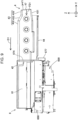
- Fig. 9 is a first view for explaining a process of attaching the cartridge 4 to the cartridge attachment section 6.
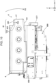
- Fig. 10 is a second view for explaining the process of attaching the cartridge 4 to the cartridge attachment section 6.
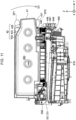
- Fig. 11 is a sectional view of FIG. 10 along the YZ plane parallel to the Y direction and the Z direction.
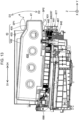
- Fig. 12 is a third view for explaining the process of attaching the cartridge 4 to the cartridge attachment section 6.
- Fig. 13 is a sectional view of FIG. 12 along the YZ plane.
- the terminal coupling process is performed by initially moving the cartridge 4 in the inserting direction D1 to a predetermined position at which a cartridge-side terminal 521 of the circuit substrate 50 comes into contact with an apparatus-side terminal 721 of the cartridge attachment section 6.
- the user pushes the first operation surface 47 in the inserting direction D1.
- the first operation surface 47 thereby receives the first load FD1 in the inserting direction D1.
- the first operation surface 47 extends from the second operation surface 435 to the side where the bottom surface 44 is located.
- the first operation surface 47 is substantially perpendicular to the inserting direction D1 in the inserted posture of the cartridge 4 and in side view.
- the direction of the normal vector V1 of the first operation surface 47 is substantially parallel to the inserting direction D1. This makes it possible to suppress the first load FD1 generated by the user pushing the first operation surface 47 in the inserting direction D1 from being distributed. Accordingly, the user is able to move the cartridge 4 in the inserting direction D1 by pushing the first operation surface 47 in the inserting direction D1 with a smaller force.
- the first load FD1 is able to be applied in a direction close to 90° with respect to the first operation surface 47, it is possible to suppress the first load FD1 from being distributed in a direction other than the inserting direction D1, thus enabling the user to move the cartridge 4 in the inserting direction D1 by pushing the first operation surface 47 in the inserting direction D1 with a smaller force. As a result, it is possible to suppress a degradation in operability of the cartridge 4 in the inserting direction D1.
- the supply section coupling process is performed after the terminal coupling process is completed by moving the cartridge 4 in the inserting direction D1 to the predetermined position at which the cartridge-side terminal 521 comes into contact with the apparatus-side terminal 721. That is, the user pushes the second operation surface 435 in the downward direction in the direction of gravity to thereby rotationally move the cartridge 4 about the rotation fulcrum 698 in the rotational-attachment direction D2 having a component in the downward direction in the direction of gravity.
- the supply section positioning section 448 receives the apparatus-side supply section positioning section 644
- the liquid supply section 442 starts to be positioned with respect to the liquid introducing section 642.
- the first angle AG1 formed by the second operation surface 435 and the inserting direction D1 is smaller than the second angle AG2 formed by the inclined surface 433 and the inserting direction D1. This makes it possible to make the angle formed by the second operation surface 435 and the downward direction in the direction of gravity close to 90° compared with an angle formed by the inclined surface 433 and the downward direction in the direction of gravity.
- the second load FD2 is able to be applied in a direction close to 90° with respect to the second operation surface 435, it is possible to suppress the second load from being distributed in a direction other than the downward direction in the direction of gravity compared with a case in which the inclined surface 433 is pushed in the downward direction in the direction of gravity.
- This makes it possible to further reduce a force for pushing the second operation surface 435 in the downward direction in the direction of gravity to move the cartridge 4 in the rotational-attachment direction D2. Accordingly, it is possible to suppress a degradation in operability of the cartridge in the rotational-attachment direction D2 when the cartridge 4 is attached.
- the second operation surface 435 in the inserted posture and in side view, is substantially perpendicular to the downward direction in the direction of gravity.
- the second load applied to the second operation surface 435 from being distributed in the supply section coupling process, thus making it possible to further reduce a force for pushing the second operation surface 435 in the downward direction in the direction of gravity to move the cartridge 4 in the rotational-attachment direction D2.
- the liquid supply section 442 of the cartridge 4 and the liquid introducing section 642 of the cartridge attachment section 6 are coupled to each other as illustrated in Fig. 13 . Accordingly, the liquid stored in the liquid containing section 450 of the cartridge 4 is supplied to the liquid introducing section 642 via the liquid supply section 442. Moreover, in the present embodiment, while the liquid is supplied from the liquid supply section 442 to the liquid introducing section 642, air that accumulates in a liquid storage section 699 of the cartridge attachment section 6 forms air bubbles, and the air bubbles flow to the liquid containing section 450 by flowing through the liquid introducing section 642 and the liquid supply section 442. Gas-liquid exchange of the liquid containing section 450 is thus performed.
- the cartridge 4 may include an air communication path that enables the liquid containing section 450 to communicate with the outside, and gas-liquid exchange may be performed via the air communication path.
- the air communication path is arranged at a position different from that of the liquid supply section 442 and is formed in, for example, a wall that forms the liquid containing section 450.
- the cartridge engagement section 497 of the cartridge 4 engages the attachment engagement section 697 of the cartridge attachment section 6, and the attachment completed state is thereby retained.
- the attachment engagement section 697 is formed in the engagement forming body 677 positioned on the first apparatus wall 67 side of the cartridge attachment section 6.
- the user When the cartridge 4 is detached from the cartridge attachment section 6, the user initially raises the first operation surface 47 side of the cartridge 4 to the upward direction side in the direction of gravity to thereby move the cartridge 4 in the coupling terminating direction D3, which has a component in the upward direction against the direction of gravity, with the rotation fulcrum 698 as the center.
- the attachment engagement section 697 constituted by a spring is moved by the cartridge 4, which terminates the engagement performed by the attachment engagement section 697 and the cartridge engagement section 497.
- the user After moving the cartridge 4 in the coupling terminating direction D3 until the cartridge 4 is brought into the inserted posture, the user holds the first operation surface 47 side of the cartridge 4 to move the cartridge 4 in the detaching direction D4. The cartridge 4 is thereby detached from the cartridge attachment section 6.
- the user since the second space SP2 is formed, the user is able to push the opposite surface 431 in the upward direction against the direction of gravity by inserting a hand into the second space SP2. Moreover, in the inserted posture illustrated in Fig. 11 , since the first space SP1 and the second space SP2 are formed, the user is able to move the cartridge 4 in the detaching direction D4 by inserting a hand into the first space SP1 and the second space SP2 and holding the second operation surface 435 and the opposite surface 431.
- the cartridge 4 includes the main surface 432 that constitutes the top surface 43 and the second operation surface 435 that constitutes the top surface 43 and is positioned on the downward direction side in the direction of gravity with respect to the main surface 432. This makes it possible to suppress an increase in the size of the outer shape of the cartridge 4 compared with a case in which the main surface 432 and the second operation surface 435 are at the same height.
- the cartridge 4 includes the inclined surface 433 positioned inward toward the second operation surface 435.
- the cartridge 4 includes the inclined surface 433 that is inclined with respect to the inserting direction D1 so as to be positioned on the bottom surface 44 side toward the detaching direction D4 side.
- This also makes it possible to suppress an increase in the size of the outer shape of the cartridge 4. Suppressing an increase in the size of the outer shape of the cartridge 4 reduces the weight of the cartridge 4 and enables the user to easily hold the cartridge 4, thus making it possible to suppress a degradation in operability for the user to attach or detach the cartridge 4 to or from the printing apparatus 10.
- the disclosure is not limited to an ink jet printer and an ink cartridge therefor and can also be applied to a cartridge attached to any printing apparatus that ejects a liquid other than ink.
- the disclosure can be applied to various printing apparatuses as follows and cartridges therefor:
- liquid droplets refers to a state of liquid ejected from the printing apparatus, and examples thereof include a granular shape, a tear shape, and a thread-like trailing shape.
- liquid here refers to any material that is able to be ejected by the printing apparatus.
- liquid may be any material as long as it is a material in a state in which a substance is in a liquid phase, and examples thereof include a liquid-state material having high or low viscosity and a liquid-state material such as a sol, gel water, other inorganic solvents, an organic solvent, a solution, a liquid resin, and a liquid metal.
- liquid further include, in addition to liquid as one state of a substance, materials in which particles of a functional material having solids such as pigments and metal particles are dissolved, dispersed, or mixed in a solvent.
- representative examples of liquid include ink as described in the embodiment described above, liquid crystal, and the like.
- the ink include various liquid compositions such as typical water-based ink, oilbased ink, gel ink, and hot-melt ink.
- the main surface 432 and the inclined surface 433 of the cartridge 4 have a planar shape, but the shape is not limited to this.
- the inclined surface 433 may have a curved surface shape that protrudes to the outside of the cartridge 4 or a curved surface shape that protrudes to the inside of the cartridge 4.
- the inclined surface 433 may be constituted by a combination of a plurality of planes.
- the inclined surface 433 may be any surface that couples the main surface 432 and the second operation surface 435 and may be a surface extending in, for example, the downward direction in the direction of gravity.
- the disclosure is not limited to the embodiments described above and can be implemented in various configurations within a range not departing from the gist of the disclosure.
- technical features in the embodiments corresponding to technical features in the aspects described below can be replaced or combined as appropriate.
- the technical features can be omitted as appropriate unless the technical features are described as essential in the present specification.
- the disclosure is able to be implemented in an aspect of a manufacturing method of a cartridge, a printing system including a cartridge and a printing apparatus, and the like in addition to the above-described aspects.
Landscapes
- Ink Jet (AREA)
- Feeding And Guiding Record Carriers (AREA)
- Liquid Crystal (AREA)
- Sheets, Magazines, And Separation Thereof (AREA)
Applications Claiming Priority (4)
| Application Number | Priority Date | Filing Date | Title |
|---|---|---|---|
| JP2021045568A JP7687009B2 (ja) | 2021-03-19 | 2021-03-19 | カートリッジ |
| JP2021099174 | 2021-06-15 | ||
| JP2022010594A JP7806519B2 (ja) | 2021-06-15 | 2022-01-27 | カートリッジ |
| PCT/JP2022/010222 WO2022196482A1 (ja) | 2021-03-19 | 2022-03-09 | カートリッジ |
Publications (2)
| Publication Number | Publication Date |
|---|---|
| EP4309902A1 true EP4309902A1 (de) | 2024-01-24 |
| EP4309902A4 EP4309902A4 (de) | 2025-03-19 |
Family
ID=83320572
Family Applications (1)
| Application Number | Title | Priority Date | Filing Date |
|---|---|---|---|
| EP22771233.8A Pending EP4309902A4 (de) | 2021-03-19 | 2022-03-09 | Kartusche |
Country Status (8)
| Country | Link |
|---|---|
| US (1) | US12330426B2 (de) |
| EP (1) | EP4309902A4 (de) |
| KR (1) | KR20230158523A (de) |
| CN (1) | CN117042972B (de) |
| BR (1) | BR112023018221A2 (de) |
| MX (1) | MX2023010793A (de) |
| TW (1) | TWI804235B (de) |
| WO (1) | WO2022196482A1 (de) |
Family Cites Families (27)
| Publication number | Priority date | Publication date | Assignee | Title |
|---|---|---|---|---|
| EP0424133B1 (de) | 1989-10-20 | 1995-03-22 | Canon Kabushiki Kaisha | Kassette mit Tintenvorratsbehälter auf einem Farbstrahlgerät aufstellbar |
| JP2675876B2 (ja) | 1989-10-22 | 1997-11-12 | キヤノン株式会社 | インクジェットヘッドカートリッジ及び該カートリッジを搭載したインクジェット記録装置 |
| JP3582592B2 (ja) * | 2001-04-03 | 2004-10-27 | セイコーエプソン株式会社 | インクカートリッジ、及びインクジェット記録装置 |
| JP3251881B2 (ja) | 1996-08-02 | 2002-01-28 | キヤノン株式会社 | 液体収納容器及び該液体収納容器を備えるインクジェットカートリッジ及び該インクジェットカートリッジを備えるインクジェット記録装置 |
| US6305794B1 (en) | 1996-08-02 | 2001-10-23 | Canon Kabushiki Kaisha | Liquid container, ink jet cartridge having same and manufacturing method of the container |
| US5949459A (en) * | 1997-06-04 | 1999-09-07 | Hewlett-Packard Company | Method and apparatus for securing an ink container |
| US7178911B2 (en) * | 2001-03-30 | 2007-02-20 | Brother Kogyo Kabushiki Kaisha | Ink cartridge |
| JP3624950B2 (ja) * | 2002-11-26 | 2005-03-02 | セイコーエプソン株式会社 | インクカートリッジ |
| JP2006043922A (ja) * | 2004-07-30 | 2006-02-16 | Canon Inc | インクタンク、インクタンクホルダ、前記インクタンクの装着方法および記録ヘッドカートリッジ |
| JP2006056118A (ja) * | 2004-08-19 | 2006-03-02 | Canon Inc | インクタンク、インクタンクホルダ、カートリッジ、および記録装置 |
| JP2007283557A (ja) | 2006-04-13 | 2007-11-01 | Seiko Epson Corp | 液体収容体 |
| JP5447214B2 (ja) * | 2010-06-17 | 2014-03-19 | ブラザー工業株式会社 | 液体容器及びその製造方法 |
| WO2013105143A1 (en) * | 2012-01-12 | 2013-07-18 | Seiko Epson Corporation | Cartridge and printing material supply system |
| US8646889B2 (en) | 2012-01-13 | 2014-02-11 | Seiko Epson Corporation | Cartridge and printing device |
| JP5927954B2 (ja) | 2012-02-06 | 2016-06-01 | セイコーエプソン株式会社 | カートリッジ及び印刷装置 |
| JP2013180523A (ja) * | 2012-03-02 | 2013-09-12 | Seiko Epson Corp | カートリッジ |
| JP6065684B2 (ja) * | 2013-03-22 | 2017-01-25 | セイコーエプソン株式会社 | 印刷装置 |
| JP6494352B2 (ja) * | 2014-05-30 | 2019-04-03 | キヤノン株式会社 | 液体吐出ヘッド |
| JP6512774B2 (ja) * | 2014-08-25 | 2019-05-15 | キヤノン株式会社 | 液体収納容器の保持部材、プリントヘッドおよびプリンタ |
| JP6424704B2 (ja) | 2015-03-27 | 2018-11-21 | ブラザー工業株式会社 | 液体カートリッジ |
| CN108566776A (zh) * | 2015-12-28 | 2018-09-21 | 精工爱普生株式会社 | 液体供给单元 |
| ES2959755T3 (es) | 2016-04-20 | 2024-02-28 | Videojet Technologies Inc | Cartucho e impresora |
| JP6878810B2 (ja) * | 2016-09-30 | 2021-06-02 | ブラザー工業株式会社 | 印刷流体カートリッジ |
| CN110023090B (zh) * | 2017-07-31 | 2021-08-17 | 兄弟工业株式会社 | 打印流体盒与包括打印流体盒和打印流体消耗设备的系统 |
| JP7035714B2 (ja) * | 2018-03-29 | 2022-03-15 | ブラザー工業株式会社 | 液体カートリッジ及びシステム |
| JP7163675B2 (ja) | 2018-08-31 | 2022-11-01 | ブラザー工業株式会社 | 液体供給装置及び画像記録装置 |
| JP7208785B2 (ja) * | 2018-12-26 | 2023-01-19 | セイコーエプソン株式会社 | カートリッジ |
-
2022
- 2022-03-09 CN CN202280020729.8A patent/CN117042972B/zh active Active
- 2022-03-09 MX MX2023010793A patent/MX2023010793A/es unknown
- 2022-03-09 WO PCT/JP2022/010222 patent/WO2022196482A1/ja not_active Ceased
- 2022-03-09 KR KR1020237033777A patent/KR20230158523A/ko active Pending
- 2022-03-09 BR BR112023018221A patent/BR112023018221A2/pt unknown
- 2022-03-09 US US18/280,623 patent/US12330426B2/en active Active
- 2022-03-09 EP EP22771233.8A patent/EP4309902A4/de active Pending
- 2022-03-16 TW TW111109550A patent/TWI804235B/zh active
Also Published As
| Publication number | Publication date |
|---|---|
| EP4309902A4 (de) | 2025-03-19 |
| US12330426B2 (en) | 2025-06-17 |
| CN117042972B (zh) | 2026-03-17 |
| WO2022196482A1 (ja) | 2022-09-22 |
| TW202237416A (zh) | 2022-10-01 |
| US20240140102A1 (en) | 2024-05-02 |
| CN117042972A (zh) | 2023-11-10 |
| MX2023010793A (es) | 2023-11-24 |
| TWI804235B (zh) | 2023-06-01 |
| KR20230158523A (ko) | 2023-11-20 |
| BR112023018221A2 (pt) | 2023-10-03 |
Similar Documents
| Publication | Publication Date | Title |
|---|---|---|
| JP6409994B2 (ja) | カートリッジ | |
| EP4063130B1 (de) | Kartusche | |
| EP3974195B1 (de) | Kartusche, drucksystem und druckvorrichtung | |
| US12311671B2 (en) | Cartridge, printing system, and printing apparatus | |
| JP2022144519A (ja) | カートリッジ | |
| US12330424B2 (en) | Cartridge and printing system | |
| JP2022148023A (ja) | カートリッジ | |
| JP2022096205A (ja) | カートリッジ、印刷装置、および、印刷システム | |
| CN103568571B (zh) | 盒 | |
| US12330426B2 (en) | Cartridge | |
| JP7806519B2 (ja) | カートリッジ | |
| US12434481B2 (en) | Attachment and printing system | |
| EP4357142A1 (de) | Kartusche und drucksystem | |
| JP2023009790A (ja) | カートリッジ | |
| JP2024024218A (ja) | カートリッジ |
Legal Events
| Date | Code | Title | Description |
|---|---|---|---|
| STAA | Information on the status of an ep patent application or granted ep patent |
Free format text: STATUS: THE INTERNATIONAL PUBLICATION HAS BEEN MADE |
|
| PUAI | Public reference made under article 153(3) epc to a published international application that has entered the european phase |
Free format text: ORIGINAL CODE: 0009012 |
|
| STAA | Information on the status of an ep patent application or granted ep patent |
Free format text: STATUS: REQUEST FOR EXAMINATION WAS MADE |
|
| 17P | Request for examination filed |
Effective date: 20231017 |
|
| AK | Designated contracting states |
Kind code of ref document: A1 Designated state(s): AL AT BE BG CH CY CZ DE DK EE ES FI FR GB GR HR HU IE IS IT LI LT LU LV MC MK MT NL NO PL PT RO RS SE SI SK SM TR |
|
| DAV | Request for validation of the european patent (deleted) | ||
| DAX | Request for extension of the european patent (deleted) | ||
| A4 | Supplementary search report drawn up and despatched |
Effective date: 20250214 |
|
| RIC1 | Information provided on ipc code assigned before grant |
Ipc: B41J 2/175 20060101AFI20250210BHEP |
|
| R17P | Request for examination filed (corrected) |
Effective date: 20231017 |
|
| GRAP | Despatch of communication of intention to grant a patent |
Free format text: ORIGINAL CODE: EPIDOSNIGR1 |
|
| STAA | Information on the status of an ep patent application or granted ep patent |
Free format text: STATUS: GRANT OF PATENT IS INTENDED |