EP4303094B1 - Gabelanordnung für autonome mobile roboter und automatisierte geführte fahrzeuge - Google Patents
Gabelanordnung für autonome mobile roboter und automatisierte geführte fahrzeuge Download PDFInfo
- Publication number
- EP4303094B1 EP4303094B1 EP23178468.7A EP23178468A EP4303094B1 EP 4303094 B1 EP4303094 B1 EP 4303094B1 EP 23178468 A EP23178468 A EP 23178468A EP 4303094 B1 EP4303094 B1 EP 4303094B1
- Authority
- EP
- European Patent Office
- Prior art keywords
- roller
- fork
- rotor shaft
- motor
- movement
- Prior art date
- Legal status (The legal status is an assumption and is not a legal conclusion. Google has not performed a legal analysis and makes no representation as to the accuracy of the status listed.)
- Active
Links
Images


Classifications
-
- B—PERFORMING OPERATIONS; TRANSPORTING
- B62—LAND VEHICLES FOR TRAVELLING OTHERWISE THAN ON RAILS
- B62B—HAND-PROPELLED VEHICLES, e.g. HAND CARTS OR PERAMBULATORS; SLEDGES
- B62B3/00—Hand carts having more than one axis carrying transport wheels; Steering devices therefor; Equipment therefor
- B62B3/04—Hand carts having more than one axis carrying transport wheels; Steering devices therefor; Equipment therefor involving means for grappling or securing in place objects to be carried; Loading or unloading equipment
- B62B3/06—Hand carts having more than one axis carrying transport wheels; Steering devices therefor; Equipment therefor involving means for grappling or securing in place objects to be carried; Loading or unloading equipment for simply clearing the load from the ground
- B62B3/0612—Hand carts having more than one axis carrying transport wheels; Steering devices therefor; Equipment therefor involving means for grappling or securing in place objects to be carried; Loading or unloading equipment for simply clearing the load from the ground power operated
-
- B—PERFORMING OPERATIONS; TRANSPORTING
- B66—HOISTING; LIFTING; HAULING
- B66F—HOISTING, LIFTING, HAULING OR PUSHING, NOT OTHERWISE PROVIDED FOR, e.g. DEVICES WHICH APPLY A LIFTING OR PUSHING FORCE DIRECTLY TO THE SURFACE OF A LOAD
- B66F9/00—Devices for lifting or lowering bulky or heavy goods for loading or unloading purposes
- B66F9/06—Devices for lifting or lowering bulky or heavy goods for loading or unloading purposes movable, with their loads, on wheels or the like, e.g. fork-lift trucks
- B66F9/075—Constructional features or details
- B66F9/12—Platforms; Forks; Other load supporting or gripping members
- B66F9/122—Platforms; Forks; Other load supporting or gripping members longitudinally movable
-
- B—PERFORMING OPERATIONS; TRANSPORTING
- B62—LAND VEHICLES FOR TRAVELLING OTHERWISE THAN ON RAILS
- B62B—HAND-PROPELLED VEHICLES, e.g. HAND CARTS OR PERAMBULATORS; SLEDGES
- B62B3/00—Hand carts having more than one axis carrying transport wheels; Steering devices therefor; Equipment therefor
- B62B3/04—Hand carts having more than one axis carrying transport wheels; Steering devices therefor; Equipment therefor involving means for grappling or securing in place objects to be carried; Loading or unloading equipment
- B62B3/06—Hand carts having more than one axis carrying transport wheels; Steering devices therefor; Equipment therefor involving means for grappling or securing in place objects to be carried; Loading or unloading equipment for simply clearing the load from the ground
- B62B3/0625—Hand carts having more than one axis carrying transport wheels; Steering devices therefor; Equipment therefor involving means for grappling or securing in place objects to be carried; Loading or unloading equipment for simply clearing the load from the ground using rigid mechanical lifting mechanisms, e.g. levers, cams or gears
-
- B—PERFORMING OPERATIONS; TRANSPORTING
- B62—LAND VEHICLES FOR TRAVELLING OTHERWISE THAN ON RAILS
- B62B—HAND-PROPELLED VEHICLES, e.g. HAND CARTS OR PERAMBULATORS; SLEDGES
- B62B3/00—Hand carts having more than one axis carrying transport wheels; Steering devices therefor; Equipment therefor
- B62B3/04—Hand carts having more than one axis carrying transport wheels; Steering devices therefor; Equipment therefor involving means for grappling or securing in place objects to be carried; Loading or unloading equipment
- B62B3/06—Hand carts having more than one axis carrying transport wheels; Steering devices therefor; Equipment therefor involving means for grappling or securing in place objects to be carried; Loading or unloading equipment for simply clearing the load from the ground
- B62B3/0643—Hand carts having more than one axis carrying transport wheels; Steering devices therefor; Equipment therefor involving means for grappling or securing in place objects to be carried; Loading or unloading equipment for simply clearing the load from the ground the wheels remaining stationary while the supporting surface is lifted
-
- B—PERFORMING OPERATIONS; TRANSPORTING
- B66—HOISTING; LIFTING; HAULING
- B66F—HOISTING, LIFTING, HAULING OR PUSHING, NOT OTHERWISE PROVIDED FOR, e.g. DEVICES WHICH APPLY A LIFTING OR PUSHING FORCE DIRECTLY TO THE SURFACE OF A LOAD
- B66F9/00—Devices for lifting or lowering bulky or heavy goods for loading or unloading purposes
- B66F9/06—Devices for lifting or lowering bulky or heavy goods for loading or unloading purposes movable, with their loads, on wheels or the like, e.g. fork-lift trucks
- B66F9/075—Constructional features or details
- B66F9/12—Platforms; Forks; Other load supporting or gripping members
-
- B—PERFORMING OPERATIONS; TRANSPORTING
- B66—HOISTING; LIFTING; HAULING
- B66F—HOISTING, LIFTING, HAULING OR PUSHING, NOT OTHERWISE PROVIDED FOR, e.g. DEVICES WHICH APPLY A LIFTING OR PUSHING FORCE DIRECTLY TO THE SURFACE OF A LOAD
- B66F9/00—Devices for lifting or lowering bulky or heavy goods for loading or unloading purposes
- B66F9/06—Devices for lifting or lowering bulky or heavy goods for loading or unloading purposes movable, with their loads, on wheels or the like, e.g. fork-lift trucks
- B66F9/075—Constructional features or details
- B66F9/20—Means for actuating or controlling masts, platforms, or forks
-
- B—PERFORMING OPERATIONS; TRANSPORTING
- B62—LAND VEHICLES FOR TRAVELLING OTHERWISE THAN ON RAILS
- B62B—HAND-PROPELLED VEHICLES, e.g. HAND CARTS OR PERAMBULATORS; SLEDGES
- B62B2203/00—Grasping, holding, supporting the objects
- B62B2203/20—Grasping, holding, supporting the objects using forks or tines
Definitions
- the invention generally relates to fork assemblies, and, more particularly, to a fork assembly for autonomous mobile robots and automated guided vehicles.
- AGVs automated guided vehicles
- AMRs autonomous mobile robots
- AMRs/AGVs fork-type autonomous mobile robots
- AMRs fork-type autonomous mobile robots
- AMRs are suited for handling pallets and are mostly designed with two forks.
- AMRs are very bulky in nature and are designed specifically for a cart handling application and have large openings.
- Such AMRs also are equipped with a mast unit for lifting of payload, which results in higher design and infrastructure costs.
- Document DE 10 2012 108 118 A1 discloses a fork assembly comprising a fork motor and rollers inside a construction of plates, to force the plates away from each other for lifting. Further examples of prior art fork assemblies are disclosed in US 2018/0370778 A1 , in CN 211393743 U and in WO 2006/130003 A1 .
- Embodiments of the present invention present technological improvements as solutions to one or more of the above-mentioned technical problems recognized by the inventors in conventional systems.
- a fork assembly for autonomous mobile robots and automated guided vehicles.
- the fork assembly a first plate having a first end and a second end, wherein the first plate comprises a first side wall and a second side wall, wherein each of the first side wall and the second side wall comprises a first Linear Motion (LM) guide rail and a second Linear Motion (LM) guide rail mounted therein respectively, and wherein each of the first Linear Motion (LM) guide rail and the second Linear Motion (LM) guide rail comprises one or more LM blocks; a first motor mount bracket and a second motor mount bracket mounted on an inner surface of the first plate, wherein each of the first motor mount bracket and the second motor mount bracket comprises a corresponding hole; a first fork motor and a second fork motor mounted to the corresponding hole of the first motor mount bracket and the second motor mount bracket, wherein the first fork motor and the second fork motor comprises a first rotor shaft and a second rotor shaft, each of the first rotor shaft and the second rotor
- first motor mount bracket and the second motor mount bracket are mounted at a position on the inner surface of the first plate such that the first fork motor and the second fork motor are separated by a pre-defined distance.
- first fork motor and the second fork motor are facing opposite to each other.
- the fork assembly further comprises a roller resting region at the second end of each of the first roller guide and the second roller guide.
- first roller guide and the second roller guide are adjacent to a first corresponding side wall and a second corresponding side wall of the first roller movement enabler block and the second roller movement enabler block.
- first roller guide and the second roller guide are tapered at a first pre-defined angle amongst the one or more pre-defined angles with reference to height of the first roller movement enabler block and the second roller movement enabler block.
- first roller guide and the second roller guide are tapered at a second pre-defined angle amongst the one or more pre-defined angles with reference to width of a tapered region formed on the first roller guide (130A) and the second roller guide of the first roller movement enabler block and the second roller movement enabler block.
- the fork assembly comprises a first enclosure and a second enclosure, wherein each of the first enclosure and the second enclosure is configured to accommodate the first rotor shaft and the second rotor shaft.
- first fork motor and the second fork motor are configured to rotate the first rotor shaft and the second rotor shaft in a first direction.
- Rotation of the first rotor shaft and the second rotor shaft drives the first roller movement enabler block and the second roller movement enabler block in a second direction.
- Driving of the first roller movement enabler block and the second roller movement enabler block in the second direction causes the first roller and the second roller to move from a position to displace the second plate from an initial position to a desired position.
- first fork motor and the second fork motor are configured to rotate the first rotor shaft and the second rotor shaft in a third direction.
- Rotation of the first rotor shaft and the second rotor shaft drives the first roller movement enabler block and the second roller movement enabler block in a second direction.
- Driving of the first roller movement enabler block and the second roller movement enabler block in the second direction causes the first roller and the second roller to move from a position to displace the second plate from an initial position to a desired position.
- the second plate attains a final position
- the fork assembly further comprises a first retainer and a second retainer.
- Each of the first retainer and the second retainer comprises a first flange and a second flange; and a compression spring between the first flange and the second flange.
- the first retainer and the second retainer are configured to counter an undesired movement of the second plate.
- AMRs fork type autonomous mobile robots
- AMRS fork type autonomous mobile robots
- Such AMRs also are equipped with a mast unit for lifting of payload, which results in further higher design and infrastructure costs.
- Embodiments of the present disclosure provide a fork assembly that when integrated with autonomous mobile robots (AMRs) and/or Automated Guided Vehicles (AGVs) enables lifting of various payloads.
- AMRs autonomous mobile robots
- AGVs Automated Guided Vehicles
- the fork assembly when integrated with autonomous mobile robots (AMRs) and/or Automated Guided Vehicles (AGVs) serves as a helpful compact component in the field where there is requirement of lifting of the payloads and transferring of payloads to desired locations.
- the fork assembly structurally comprises various components in such a way that it is capable of lifting very high loads with low power from motor and/or battery.
- the designed fork assembly described herein helps cut down the motor power and torque required to lift a heavy load (or payload) hence allowing higher capacity payloads to lifted with low-capacity motors.
- the fork assembly is structurally designed for integration with AMRs/AGVs for lifting pallets and roller cages with utmost efficiency in terms of energy usage, thereby ensuring energy savings and reduced carbon footprint.
- FIGS. 1 through 10 where similar reference characters denote corresponding features consistently throughout the figures, there are shown preferred embodiments and these embodiments are described in the context of the following exemplary system and/or method.
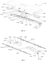
- FIG. 1A illustrates a front perspective view of a fork assembly 100, in accordance with an embodiment of the present disclosure.
- FIG. 1B illustrates a rear perspective view of the fork assembly 100, in accordance with an embodiment of the present disclosure.
- FIG. 1C illustrates a perspective view of the fork assembly 100 depicting various integral components comprised therein, in accordance with an embodiment of the present disclosure.
- the fork assembly 100 may also be referred as 'apparatus 100' and interchangeably used herein.
- the apparatus 100 will now be explained in conjunction with FIGS. 1A through 1C .
- the apparatus 100/fork assembly 100 comprises a first plate 102.
- the first plate 102 is also referred as a bottom plate and may be interchangeably used herein.
- the first plate 102 (bottom plate) comprises having a first end 104A and a second end 104B.
- the first plate 102 further comprises a first side wall 106A and a second side wall 106B.
- Each of the first side wall 106A and the second side wall 106B comprises a first Linear Motion (LM) guide rail 108A and a second Linear Motion (LM) guide rail 108B mounted therein respectively.
- LM Linear Motion
- LM Linear Motion
- LM Linear Motion
- LM Linear Motion
- LM Linear Motion
- LM Linear Motion
- LM Linear Motion
- LM Linear Motion
- first side wall 106A has the first LM guide rail 108A mounted on it and the second side wall 106B has the second LM guide rail 108B mounted on it.
- Length of the first Linear Motion (LM) guide rail 108A and the second Linear Motion (LM) guide rail 108B may vary based on the structural design of the fork assembly 100 and the first plate 102.
- one or more LM blocks 110A-N are fixed (or attached or connected) to each of the first Linear Motion (LM) guide rail 108A and the second Linear Motion (LM) guide rail 108B.
- These LM blocks 110A-N provide support to the first roller movement enabler block 124A and the second roller movement enabler block 124B and take both the load coming from the second plate 134 also the moment load acting on it.
- the first roller movement enabler block 124A and the second roller movement enabler block 124B are suspended on the LM blocks 110A-N without touching the inner surface of the first plate 102 (or the bottom surface of the fork assembly 100), hence providing it with smooth linear motion.
- the first and the second LM guide rails 108A-B and the one or more LM blocks 110A-N are depicted in FIG. 2 . More specifically, FIG. 2 , with reference to FIGS. 1A through 1C , depicts various components comprised in the fork assembly 100, in accordance with an embodiment of the present disclosure.
- the fork assembly 100 further comprises a first motor mount bracket 112A and a second motor mount bracket 112B.
- the first motor mount bracket 112A and the second motor mount bracket 112B are mounted on an inner surface of the first plate 102.
- Each of the first motor mount bracket 112A and the second motor mount bracket 112B comprises a corresponding hole 116A-B.
- the first motor mount bracket 112A comprises the hole 116A
- the second motor mount bracket 112B comprises the hole 116B.
- the fork assembly 100 further comprises a first fork motor 114A and a second fork motor 114B that are mounted to the respective holes 116A-B.
- the first fork motor 114A is mounted to the hole 116A such that the first fork motor 114A is firmly held to prevent from any loose ends and fall.
- the first fork motor 114B is mounted to the hole 116B such that the first fork motor 114B is firmly held to prevent from any loose ends and fall.
- first motor mount bracket 112A and the second motor mount bracket 112B are mounted at a position on the inner surface of the first plate 102 such that the first fork motor 114A and the second fork motor 114B are separated by a pre-defined distance (e.g., say ' x ' distance - which may be in millimeter, centimeter, and the like).
- a pre-defined distance e.g., say ' x ' distance - which may be in millimeter, centimeter, and the like.
- the first fork motor 114A and the second fork motor 114B are positioned such that they face opposite to each other. Position of the first fork motor 114A with respect to position of the second fork motor 114B and these being separated by the pre-defined distance (e.g., ' x ' distance) is shown in FIG. 1C .
- Each of the first fork motor 114A and the second fork motor 114B comprises a first rotor shaft 118A and a second rotor shaft 118B.
- the first fork motor 114A comprises the first rotor shaft 118A
- the second fork motor 114B comprises the second rotor shaft 118B.
- a typical motor setup in such fork assembly 100 comprises a stator and a rotor (not shown in FIGS.).
- the rotor comprises a shaft which has two ends.
- each of the first rotor shaft 118A and the second rotor shaft 118B comprise a first end 120A and a second end 120B.
- the first end 120A of each of the first rotor shaft 118A and the second rotor shaft 118B serves as an integral component of the first fork motor 114A and the second fork motor 114B respectively.
- the first end 120A is either an integral component of the rotor or connected to the rotor.
- the second end 120B of the two shafts e.g., the first rotor shaft and the second rotor shaft
- the fork assembly 100 further comprises a first Linear Motion (LM) nut 122A and a second Linear Motion (LM) nut 122B.
- the first LM nut 122A is connected to the second end 120B of the first rotor shaft 118A and the second LM nut 122A is connected to the second end 120B of the second rotor shaft 118B.
- the first LM nut 122A and the second LM nut 122B are configured to receive the second end 120B of the of the first and the second rotor shaft 118A-B respectively.
- at least a portion of the second end 120B serving as the lead screw is configured to be accommodate in the first LM nuts 122A and the second LM nuts 122B respectively.
- the first end 120A and the second end 120B and their coupling and/or connectivity to the fork motors 114A-B and the first and second LM nuts 122A-B is depicted in FIG. 1C .
- the fork assembly 100 further comprises a first roller movement enabler block 124A and a second roller movement enabler block 124B.
- the first roller movement enabler block 124A and the second roller movement enabler block 124B may also referred as inclined block and interchangeably used herein, due to their structural design and requirement and formation of integral component of the fork assembly 100.
- Each of the first roller movement enabler block 124A and the second roller movement enabler block 124B comprises of a first side 126A and a second side 126B.
- the first side 126A of the first roller movement enabler block 124A and the second roller movement enabler block 124B comprises a corresponding hole 128A-B.
- the first side 126A of the first roller movement enabler block 124A comprises the hole 128A
- the first side 126A of the second roller movement enabler block 124B comprises the hole 128B.
- the first side 126A is designed as a square or rectangular block and forms a hollow space within it.
- the corresponding holes 128A-B are configured to receive the first LM nut 120A and the second LM nut 120B respectively.
- the hole 128A comprised on the first side 126A of the first roller movement enabler block 124A is configured to receive the first LM nut 120A
- the hole 128B comprised on the first side 126A of the second roller movement enabler block 124B is configured to receive the second LM nut 120B.
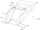
- the second side 126B of the first roller movement enabler block 124A and the second roller movement enabler block 124B comprises a first roller guide 130A and a second roller guide 130B that are tapered at one or more pre-defined angles.
- first roller guide 130A and the second roller guide 130B are tapered at a first pre-defined angle (amongst the one or more pre-defined angles) with reference to height of the first roller movement enabler block 124A and the second roller movement enabler block 124B.
- first roller guide 130A and the second roller guide 130B are tapered at a second pre-defined angle (amongst the one or more pre-defined angles) with reference to width of a tapered region 148 formed on the first roller guide 130A and the second roller guide 130B of the first roller movement enabler block 124A and the second roller movement enabler block 124B.
- Each of the first roller guide 130A and the second roller guide (130B) comprise a first end 132A and a second end 132B.
- the width of the tapered region 148 extends from the first end 132A through the second end 132B, in an example embodiment of the present disclosure.
- the first roller guide 130A and the second roller guide 130B are adjacent to a first corresponding side wall and a second corresponding side wall of the first roller movement enabler block 124A and the second roller movement enabler block 124B. More specifically, the first roller guide 130A is adjacent to the first corresponding side wall of the first roller movement enabler block 124A and the second roller movement enabler block 124B and tapered in nature to from the tapered region 148.
- FIG. 6 with reference to FIGS.
- FIG. 1A through 5 illustrates a perspective of the first roller movement enabler block 126A and the second roller movement enabler block 124B with various components comprised therein, in accordance with an embodiment of the present disclosure.
- the first pre-defined angle and the second pre-defined angles ⁇ and ⁇ amongst the one or more pre-defined angles are formed by way of structural design (e.g., tapering) of the first roller guide 130A and the second roller guide 130B of the first roller movement enabler block 124A and the second roller movement enabler block 124B and are depicted in FIG. 6 .
- the fork assembly 100 further comprises a second plate 134.
- the second plate 134 is also referred as a top plate and may be interchangeably used herein.
- the first end 104A and the second end 104B of the first plate 102 may also be realized for the second plate 134, in an example embodiment of the present disclosure. This realization may be accounted since the length and width of the first plate 102 and the second plate 134 are similar in design and structure.
- the fork assembly 100 further comprises a first roller mount 136A and a second roller mount 136B.
- Each of the first roller mount 136A and the second roller mount 136B comprises a first end 138A and a second end 138B.
- the first end 138A of the first roller mount 136A and the second roller mount 136B is fixed to the second plate 134.
- the first roller mount 136A is positioned at the first end 104A of the first plate 102 and the second plate 134
- the second roller mount 136B is positioned at the second end 104B of the first plate 102 and the second plate 134 respectively.
- Top surface of the first roller mount 136A and the second roller mount 136A are either welded to an inner surface of the second plate 134 (top plate) or fixed to the second plate 134 in an alternative manner.
- the top surface of the first roller mount 136A and the second roller mount 136B may be provisioned by one or more holes.
- the top plate may also be provisioned by one or more holes (not shown in FIGS.).
- the first roller mount 136A and the second roller mount 136B may be fixed to (or connected to) the second plate 134 via the one or more associated holes comprised therein using one or more screw mechanisms.
- Each of the first roller mount 136A and the second roller mount 136B comprises a first flange 140A and a second flange 140B.
- Each of the first flange 140A and the second flange 140B comprises a corresponding hold 142A-B.
- the first flange 140A comprises the hole 142A and the second flange comprises the hole 142B.
- the fork assembly 100 further comprises a first roller 144A and a second roller 144B fixed to the corresponding hole 142A-B of the first flange 140A and the second flange 140B respectively.
- a set of the first roller 144A is used by the fork assembly 100.
- a set of the second roller 144B is used by the fork assembly 100.
- the first roller 144A is connected to (or fixed to or attached to) the first flange 140A through the hole 142A and the second roller 144B is connected to (or fixed to or attached to) the second flange 140A through the hole 142B.
- FIG. 7 illustrates a roller mount and one or more rollers coupled to respective holes 142A-B of one or more flanges 140A-B of the roller mount, in accordance with an embodiment of the present disclosure.
- the first roller 144A and a second roller 144B are structurally designed, positioned, and fixed (or coupled) to the first roller mount 136A and the second roller mount 136B such that the rollers 144A-B have freedom to rotate on their own axis.
- the first roller 144A and the second roller 144B roll on the tapered region 148 during the operation of the fork assembly 100.
- the first fork motor 114A and the second fork motor 114B are configured to rotate the first rotor shaft 116A and the second rotor shaft 116B in a first direction respectively (e.g., say clockwise direction). Rotation of the first rotor shaft 116A) and the second rotor shaft 116B drives the first roller movement enabler block 124A and the second roller movement enabler block 124B in a second direction (e.g., say forward direction).
- Driving of the first roller movement enabler block 124A and the second roller movement enabler block 124B in the second direction causes the first roller 144A and the second roller 144B to move from a position to displace the second plate 134 from an initial position to a desired position.
- first fork motor 114A and the second fork motor 114B are powered with power supply (e.g., either by mains supply or through batteries) to rotate the first rotor shaft 116A and the second rotor shaft 116B in a first direction (e.g., say clockwise direction).
- a first direction e.g., say clockwise direction.
- Rotation of the first rotor shaft 116A and the second rotor shaft 116B in the clockwise direction drives the first roller movement enabler block 124A and the second roller movement enabler block 124B in the forward direction.
- Driving of the first roller movement enabler block 124A and the second roller movement enabler block 124B in the forward direction causes the first roller 144A and the second roller 144B to move on the tapered region 148 from a position (e.g., say initial position such as down to top rolling) to displace the second plate 134 from an initial position (e.g., say a position with reference to the base of the first plate 102 or ground surface).
- the displacement of second plate 134 in this scenario results in rising or moving of the second plate 134 in an upward direction and towards the roller resting region 146A-B.
- first fork motor 114A and the second fork motor 114B are configured to rotate the first rotor shaft 116A and the second rotor shaft 116B in a third direction respectively (e.g., say anti-clockwise direction). Rotation of the first rotor shaft 116A and the second rotor shaft 116B drives the first roller movement enabler block 124A and the second roller movement enabler block 124B in a fourth direction (e.g., say backward direction).
- Driving of the first roller movement enabler block 124A and the second roller movement enabler block 124B in the fourth direction causes the first roller 144A and the second roller 144B to move from a position (e.g., say an attained position) to displace the second plate 134 from an initial position to a desired position.
- first fork motor 114A and the second fork motor 114B are powered with power supply (e.g., either by mains supply or through batteries) to rotate the first rotor shaft 116A and the second rotor shaft 116B in a third direction (e.g., say anti-clockwise direction).
- power supply e.g., either by mains supply or through batteries
- Rotation of the first rotor shaft 116A and the second rotor shaft 116B in the anti-clockwise direction drives the first roller movement enabler block 124A and the second roller movement enabler block 124B in the backward direction.
- Driving of the first roller movement enabler block 124A and the second roller movement enabler block 124B in the backward direction causes the first roller 144A and the second roller 144B to move on the tapered region 148 from a first position (e.g., say initial position such as from top to down rolling) to displace the second plate 134 from an initial position.
- the displacement of second plate 134 in this scenario results in lowering or moving of the second plate 134 in a downward direction and away from the roller resting region 146A-B.
- swift movement (in forward and backward direction) of the first roller movement enabler block 124A and the second roller movement enabler block 124B is enabled by the first LM guide rail 108A and the second LM guide rail 108B and/or the LM blocks 110A-N.
- FIG. 5 illustrates a detailed view of a fork motor and a roller movement enabler block and other components comprised in the fork assembly 100, in accordance with an embodiment of the present disclosure.
- both the fork motors 114A-B are operated to synchronously rotate in specific direction(s) (e.g., clockwise and/or anti-clockwise/counter-clockwise directions). This is done with the help of a motor controller (not shown in FIGS. - but may be either integral to the fork assembly 100 or external connected thereto or comprised in the AMR) which controls the direction of both the fork motors 114A-B.
- a motor controller not shown in FIGS. - but may be either integral to the fork assembly 100 or external connected thereto or comprised in the AMR
- Encoder or an equivalent circuit or logic (not shown in FIGS.) in the fork motors 114A-B control the speed and position and provides feedback (based on level of lifting and lowering of the second plate 134) to the fork motors 114A-B to start or stop at various end points.
- Such operation may be controlled by the motor controller which may switch rotation via one or more logics provided by means of a system (e.g., either configured in the fork assembly 100 or externally connected to - not shown in FIGS.).
- the fork assembly 100 further comprises a first retainer 150A and a second retainer 150B.
- FIG. 3 illustrates a cross-sectional view plan of the fork assembly 100 of FIGS. 1A through 1C depicting the first retainer 150A and the second retainer 150B, in accordance with an embodiment of the present disclosure. The arrow depicted in FIG. 3 is presented to indicate the cross-sectional view plan for better understanding of the embodiments described herein.
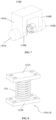
- Each of the first retainer 150A and the second retainer 150B comprises a first flange 152A and a second flange 152B at both ends of the first retainer 150A and the second retainer 150B respectively.
- FIG. 4 illustrates a cross sectional view of the fork assembly 100 of FIGS. 1A through 1C depicting the first flange 152A and the second flange 152B at both ends of the first retainer 150A and the second retainer 150B along with the compression spring 154, in accordance with an embodiment of the present disclosure.
- FIG. 8 depicts a detailed view of the first retainer 150A and the second retainer 150B along with the compression spring 154, in accordance with an embodiment of the present disclosure.
- the first retainer 150A and the second retainer 150B are configured to counter an undesired movement of the second plate 134. For instance, there could be an undesired pulling of the first plate 102 or the second plate 134. In such scenarios.
- Such counter mechanism may be achieved by either welding the first flange 152A and the second flange 152B to an inner surface of the first plate 102 and the second plate 134 (top plate) or fixed to the first plate 102 and the second plate 134 in an alternative manner.
- the first flange 152A and the second flange 152B may be provisioned by one or more holes.
- the first plate 102 and the second plate 134 may also be provisioned by one or more holes (not shown in FIGS.).
- the fork assembly 100 further comprises a first enclosure 156A and a second enclosure 156B.
- the first enclosure 156A and the second enclosure 156B are configured to accommodate the first rotor shaft 116A and the second rotor shaft 116B.
- the fork assembly 100 may form an attachable component or a fixable component to an autonomous mobile robot (AMR) or an autonomous guided vehicle (AGV) via one or more fixing components/means (e.g., either via hardware components such as clamps, or coupled via electrical buses/cables through appropriate interfaces as known in the art.
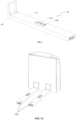
- FIG. 9 depicts the fork assembly 100 having a clamp 158, in accordance with an embodiment of the present disclosure.
- the clamp 158 may serve as a connector between an AMR/AGV and the fork assembly 100.
- FIG. 10 with reference to FIGS.
- FIG. 10 depicts a rear view and a use case scenario of the fork assembly 100 forming a part of (or connected to) the autonomous mobile robot (AMR), in accordance with an embodiment of the present disclosure.
- the fork assembly 100 when integrated to or operatively connected/coupled to the AMR (or AGV) may be equipped with other components such as a front panel that covers the integral components of the AMR/AGV.
- the AMR further comprises a display (not shown in FIGS.) to display information pertaining to the fork assembly 100, other interconnected /interoperability components, the AMR/AGV, placement/movement of the payload, and operation or operating procedures of the fork assembly 100 and the AMR/AGV, and the like.
- An emergency button may also incorporate in the AMR/AGV to bring the fork assembly 100 or the AMR/AGV to halt or stop from operating/functionality in case of anomalies, or inadvertent operations being performed (e.g., during placement and movement of the payload, navigation of the AMR/AGV, and the like).
- the AMR/AGV further comprises a light indicator (not shown in FIGS.) that indicates one or more states of the fork assembly 100 and/or the AMR/AGV via one or more light modes (e.g., green for working normal, red for malfunctioning of one or more components of the apparatus/AMR/AGV, and/or any other appropriate color modes to indicate a communication message that is specific to an operating mode or working of the fork assembly 100/AMR/AGV).
- light modes e.g., green for working normal, red for malfunctioning of one or more components of the apparatus/AMR/AGV, and/or any other appropriate color modes to indicate a communication message that is specific to an operating mode or working of the fork assembly 100/AMR/AGV.
- cameras or video capturing devices or sensors are also incorporated in the fork assembly 100 or in the AMR/AGVs to capture image/video data of the surrounding/environment during payload placement and movement/navigation.
- the cameras may be placed anywhere such as integral to the fork assembly at the tapered end (e.g., refer second end of the first plate 102) or at the other side (e.g., chassis (not shown in FIGS.) of the AMR/AGV).
- the cameras may also be referred as front camera, rear camera, side cameras, top cameras, bottom cameras, and the like and positioned accordingly.
- the AMR/AGV further comprises a rear panel (not shown in FIGS.) that is configured to cover the chassis or the entire apparatus. In other words, the rear panel may serve as a protective gear/protective cover element for the fork assembly 102.
- the fork assembly 100 or the entire AMRs/AGVs when integrated with (or connected to or attached to) the fork assembly 100 may be operated based on instructions set comprised in a system (e.g., the system is either within the fork assembly 100 or the AMR/AGV or externally connected to the fork assembly 100 via I/O communication interfaces).
- the fork assembly 100 or the AMR/AGV may comprise (or comprises) the system (not shown in FIGS) that includes a memory for storing the instructions set(s), one or more input/output communication interfaces interface(s), one or more hardware processors.
- the one or more hardware processors are communicatively coupled to the memory via the one or more communication interfaces wherein the one or more hardware processors are configured by the instructions to execute and enable operation of each component of the fork assembly 100 (and/or the AMR/AGV) as described herein. More specifically, the movement of the fork assembly 100, the AMR/AGV, the fork assembly 100 operation and the working of the other components comprised in the fork assembly 100 as described above may be based on instructions set being executed by the one or more hardware processors for handling payload (either placed on the fork assembly 100 or to be placed or to be moved from one location to another location). Various components of the fork assembly 100 are (or may be) configured by the instructions set to perform the method described herein for handling the payload.
- the system may be mounted on the fork assembly 100, in one example embodiment of the present disclosure.
- the system may be housed on the fork assembly 100, in another example embodiment of the present disclosure.
- the system may be comprised in the fork assembly 100, in yet another example embodiment of the present disclosure.
- the system may be communicatively coupled to the fork assembly 100 via one or more communication interfaces as applicable and known in the art, in yet further example embodiment of the present disclosure.
- the fork assembly 100 (or AMR/AGV) may be provisioned with options and configured with suitable arrangement such that the fork assembly 100 can be operated via the connected/communicatively coupled system.
- the fork assembly 100 may be used and/or implemented in AMRs/AGVs for roller carts lifting, vertical rack in a goods to picker setup and the like. Other applications include, but are not limited to, warehouse and logistics environments, distribution centers where pallets and/or roller carts/cages are to be picked and placed from one location to another location.
- the fork assembly 100 may further be equipped with drive and/or swivel wheels (also referred as wheels and interchangeably used herein) that may be mounted to a bottom surface of the first plate 102 or form an integral part of the first plate 102 from bottom wherein the wheels may be mounted to wheel brackets (portion of a wheel can be seen in FIG.
- the wheels when in operation may have various degree of freedom to rotate and drive the AMRs/AGVs in one or more direction(s) during payload placement and movement from one location to desired location.
- the embodiments of the present disclosure address the technology gap by providing a compact fork assembly which can lift maximum payload with minimum possible reduced height and width of lifting mechanism. Further, length of the first plate 102 and the second plate 134 of the fork assembly 100 are structurally designed in such a way that it increases and supports bottom side of the payloads. The compactness has been brought out to address the various lifting cases in the warehouses or in the shop floors, etc. As mentioned above, the fork assembly 100 when integrated with AMRs/AGVs enables lifting of various pallets, carts/roller cages, and payloads.
Landscapes
- Engineering & Computer Science (AREA)
- Transportation (AREA)
- Structural Engineering (AREA)
- Mechanical Engineering (AREA)
- Chemical & Material Sciences (AREA)
- Combustion & Propulsion (AREA)
- Civil Engineering (AREA)
- Life Sciences & Earth Sciences (AREA)
- Geology (AREA)
- Forklifts And Lifting Vehicles (AREA)
Claims (12)
- Gabelanordnung (100), umfassend:eine erste Platte (102) mit einem ersten Ende (104A) und einem zweiten Ende (104B), wobei die erste Platte (102) ferner eine erste Seitenwand (106A) und eine zweite Seitenwand (106B) umfasst, wobei jede der ersten Seitenwand (106A) und der zweiten Seitenwand (106B) eine erste Linearbewegungsführungsschiene (108A) und eine zweite Linearbewegungsführungsschiene (108B) umfasst, die jeweils darin montiert sind, und wobei jede der ersten Linearbewegungsführungsschiene (108A) und der zweiten Linearbewegungsführungsschiene (108B) einen oder mehrere Linearbewegungsblöcke (110A-N) umfasst;eine erste Motormontagehalterung (112A) und eine zweite Motormontagehalterung (112B), die an einer Innenfläche der ersten Platte (102) montiert sind, wobei jede der ersten Motormontagehalterung (112A) und der zweiten Motormontagehalterung (112B) ein entsprechendes Loch (116A-B) umfasst;einen ersten Gabelmotor (114A) und einen zweiten Gabelmotor (114B), die an dem entsprechenden Loch (116A-B) der ersten Motormontagehalterung (112A) und der zweiten Motormontagehalterung (112B) montiert sind, wobei der erste Gabelmotor (114A) und der zweite Gabelmotor (114B) eine erste Rotorwelle (118A) und eine zweite Rotorwelle (118B) umfassen, wobei jede der ersten Rotorwelle (118A) und der zweiten Rotorwelle (118B) ein erstes Ende (120A) und ein zweites Ende (120B) umfasst, wobei das erste Ende (120A) jeder der ersten Rotorwelle (118A) und der zweiten Rotorwelle (118B) als eine integrale Komponente des ersten Gabelmotors (114A) bzw. des zweiten Gabelmotors (114B) dient;eine erste Linearbewegungsmutter (122A) und eine zweite Linearbewegungsmutter (122B), die mit dem zweiten Ende (120B) der ersten Rotorwelle (118A) bzw. der zweiten Rotorwelle (118B) verbunden sind;einen ersten Rollenbewegungsermöglichungsblock (124A) und einen zweiten Rollenbewegungsermöglichungsblock (124B), wobei jeder des ersten Rollenbewegungsermöglichungsblocks (124A) und des zweiten Rollenbewegungsermöglichungsblocks (124B) eine erste Seite (126A) und eine zweite Seite (126B) umfasst, wobei die erste Seite (126A) des ersten Rollenbewegungsermöglichungsblocks (124A) und des zweiten Rollenbewegungsermöglichungsblocks (124B) ein entsprechendes Loch (128A-B) umfasst, wobei das entsprechende Loch (128A-B) konfiguriert ist, um die erste Linearbewegungsmutter (120A) und die zweite Linearbewegungsmutter (120B) aufzunehmen, und wobei die zweite Seite (126B) des ersten Rollenbewegungsermöglichungsblocks (126A) und des zweiten Rollenbewegungsermöglichungsblocks (124B) eine erste Rollenführung (130A) und eine zweite Rollenführung (130B) umfasst, die in einem oder mehreren vordefinierten Winkeln verjüngt sind, wobei jede der ersten Rollenführung (130A) und der zweiten Rollenführung (130B) ein erstes Ende (132A) und ein zweites Ende (132B) umfasst;eine zweite Platte (134);eine erste Rollenhalterung (136A) und eine zweite Rollenhalterung (136B), wobei jede der ersten Rollenhalterung (136A) und der zweiten Rollenhalterung (136B) Folgendes umfasst:ein erstes Ende (138A) und ein zweites Ende (138B), wobei das erste Ende (138A) der ersten Rollenhalterung (136A) und der zweiten Rollenhalterung (136B) an der zweiten Platte (134) befestigt ist; undeinen ersten Flansch (140A) und einen zweiten Flansch (140B), wobei jeder des ersten Flansches (140A) und des zweiten Flansches (140B) ein entsprechendes Loch (142A-B) umfasst; undeine erste Rolle (144A) und eine zweite Rolle (144B), die an dem entsprechenden Loch (142A-B) des ersten Flansches (140A) bzw. des zweiten Flansches (140B) befestigt sind.
- Gabelanordnung nach Anspruch 1, wobei die erste Motormontagehalterung (112A) und die zweite Motormontagehalterung (112B) an einer Position an der Innenfläche der ersten Platte (102) montiert sind, sodass der erste Gabelmotor (114A) und der zweite Gabelmotor (114B) durch einen vordefinierten Abstand getrennt sind.
- Gabelanordnung nach Anspruch 1, wobei der erste Gabelmotor (114A) und der zweite Gabelmotor (114B) einander gegenüberliegen.
- Gabelanordnung nach Anspruch 1, umfassend einen Rollenauflagebereich (146A-B) an dem zweiten Ende jeder der ersten Rollenführung (130A) und der zweiten Rollenführung (130B).
- Gabelanordnung nach Anspruch 4, wobei die erste Rolle (144A) und die zweite Rolle (144B) konfiguriert sind, um sich von einer Ausgangsposition zu dem Rollenauflagebereich (144A-B) zu bewegen, sodass die zweite Platte (134) eine Endposition erreicht.
- Gabelanordnung nach Anspruch 1, wobei die erste Rollenführung (130A) und die zweite Rollenführung (130B) an eine erste entsprechende Seitenwand und eine zweite entsprechende Seitenwand des ersten Rollenbewegungsermöglichungsblocks (124A) und des zweiten Rollenbewegungsermöglichungsblocks (124B) angrenzen.
- Gabelanordnung nach Anspruch 1, wobei die erste Rollenführung (130A) und die zweite Rollenführung (130B) in einem ersten vordefinierten Winkel unter dem einen oder den mehreren vordefinierten Winkeln in Bezug auf die Höhe des ersten Rollenbewegungsermöglichungsblocks (124A) und des zweiten Rollenbewegungsermöglichungsblocks (124B) verjüngt sind.
- Gabelanordnung nach Anspruch 1, wobei die erste Rollenführung (130A) und die zweite Rollenführung (130B) in einem zweiten vordefinierten Winkel unter dem einen oder den mehreren vordefinierten Winkeln in Bezug auf die Breite eines verjüngten Bereichs (148), der auf der ersten Rollenführung (130A) und der zweiten Rollenführung (130B) des ersten Rollenbewegungsermöglichungsblocks (124A) und des zweiten Rollenbewegungsermöglichungsblocks (124B) gebildet ist, verjüngt sind.
- Gabelanordnung nach Anspruch 8, wobei der erste Gabelmotor (114A) und der zweite Gabelmotor (114B) konfiguriert sind, um die erste Rotorwelle (116A) und die zweite Rotorwelle (116B) in einer ersten Richtung zu drehen, wobei die Drehung der ersten Rotorwelle (116A) und der zweiten Rotorwelle (116B) den ersten Rollenbewegungsermöglichungsblock (124A) und den zweiten Rollenbewegungsermöglichungsblock (124B) in einer zweiten Richtung antreibt, und wobei das Antreiben des ersten Rollenbewegungsermöglichungsblocks (124A) und des zweiten Rollenbewegungsermöglichungsblocks (124B) in der zweiten Richtung bewirkt, dass sich die erste Rolle (144A) und die zweite Rolle (144B) von einer Position auf dem verjüngten Bereich (148) bewegen, um die zweite Platte (134) von einer Ausgangsposition zu einer gewünschten Position zu verschieben.
- Gabelanordnung nach Anspruch 1, wobei der erste Gabelmotor (114A) und der zweite Gabelmotor (114B) konfiguriert sind, um die erste Rotorwelle (116A) und die zweite Rotorwelle (116B) in einer dritten Richtung zu drehen, wobei die Drehung der ersten Rotorwelle (116A) und der zweiten Rotorwelle (116B) den ersten Rollenbewegungsermöglichungsblock (124A) und den zweiten Rollenbewegungsermöglichungsblock (124B) in einer vierten Richtung antreibt, und wobei das Antreiben des ersten Rollenbewegungsermöglichungsblocks (124A) und des zweiten Rollenbewegungsermöglichungsblocks (124B) in der vierten Richtung bewirkt, dass sich die erste Rolle (144A) und die zweite Rolle (144B) von einer Position bewegen, um die zweite Platte (134) von einer Ausgangsposition zu einer gewünschten Position zu verschieben.
- Gabelanordnung nach Anspruch 1, ferner umfassend eine erste Halterung (150A) und eine zweite Halterung (150B), wobei jede der ersten Halterung (150A) und der zweiten Halterung (150B) Folgendes umfasst:einen ersten Flansch (152A) und einen zweiten Flansch (152B); undeine Druckfeder (154) zwischen dem ersten Flansch (152A) und dem zweiten Flansch (152B), wobei die erste Halterung (150A) und die zweite Halterung (150B) konfiguriert sind, um einer unerwünschten Bewegung der zweiten Platte (134) entgegenzuwirken.
- Gabelanordnung nach Anspruch 1, ferner umfassend ein erstes Gehäuse (156A) und ein zweites Gehäuse (156B), wobei jedes des ersten Gehäuses (156A) und des zweiten Gehäuses (156B) konfiguriert ist, um die erste Rotorwelle (116A) und die zweite Rotorwelle (116B) aufzunehmen.
Applications Claiming Priority (1)
| Application Number | Priority Date | Filing Date | Title |
|---|---|---|---|
| IN202221038703 | 2022-07-05 |
Publications (3)
| Publication Number | Publication Date |
|---|---|
| EP4303094A1 EP4303094A1 (de) | 2024-01-10 |
| EP4303094B1 true EP4303094B1 (de) | 2024-08-21 |
| EP4303094C0 EP4303094C0 (de) | 2024-08-21 |
Family
ID=86760552
Family Applications (1)
| Application Number | Title | Priority Date | Filing Date |
|---|---|---|---|
| EP23178468.7A Active EP4303094B1 (de) | 2022-07-05 | 2023-06-09 | Gabelanordnung für autonome mobile roboter und automatisierte geführte fahrzeuge |
Country Status (2)
| Country | Link |
|---|---|
| US (1) | US11840437B1 (de) |
| EP (1) | EP4303094B1 (de) |
Families Citing this family (1)
| Publication number | Priority date | Publication date | Assignee | Title |
|---|---|---|---|---|
| NL2033726B1 (nl) * | 2022-12-15 | 2024-06-20 | Meijer Holding B V | Elektrische verlengvork voor een heftruck of palletwagen, heftruck of palletwagen voorzien daarvan en werkwijze daarvoor |
Family Cites Families (17)
| Publication number | Priority date | Publication date | Assignee | Title |
|---|---|---|---|---|
| DE4120711C1 (de) * | 1991-06-22 | 1992-04-09 | Eisenberg, Hans-Jochen, 5600 Wuppertal, De | |
| DE4209861A1 (de) | 1992-03-26 | 1993-09-30 | Linde Ag | Gabelhubwagen |
| NL9400772A (nl) | 1994-05-09 | 1995-12-01 | Kooi Beheer B V | Vorkhefwagen met vorksteun. |
| NL1030776C2 (nl) * | 2005-05-31 | 2006-12-04 | Meijer St Jabik B V Geb | Vork van een hefinrichting. |
| DE102012108118A1 (de) * | 2012-08-31 | 2014-03-06 | Hupfer Metallwerke Gmbh & Co. Kg | Fahrantrieb für Rollwagen, insbesondere Rollwagen für die Ausgabe, den Transport oder die Verteilung von Speisen |
| KR101601933B1 (ko) * | 2015-07-30 | 2016-03-10 | (주)우진쿼터스 | 가구용 리프트 |
| US10633233B2 (en) * | 2017-06-23 | 2020-04-28 | James Mathes | Pallet jack assembly |
| CA3084045A1 (en) | 2017-12-06 | 2019-05-13 | Meijer Holding B.V. | Modular sliding fork for a fork-lift truck or pallet truck, fork-lift truck or pallet truck provided therewith and method therefor |
| CN208898451U (zh) * | 2018-09-20 | 2019-05-24 | 浙江迈睿机器人有限公司 | 搬运叉车 |
| CN211393743U (zh) * | 2019-11-07 | 2020-09-01 | 浙江大华机器人技术有限公司 | 搬运车 |
| CN111362190A (zh) * | 2020-03-06 | 2020-07-03 | 安徽宇锋智能科技有限公司 | 一种货叉搬运agv |
| CN112811352A (zh) * | 2021-02-22 | 2021-05-18 | 江西省智能产业技术创新研究院 | 一种面向智慧物流的机器人叉车 |
| CN113003491B (zh) * | 2021-03-10 | 2024-03-08 | 广州蓝胖子移动科技有限公司 | 一种用于货物运输的全自动电动叉车及移送方法 |
| CN216336405U (zh) * | 2021-03-25 | 2022-04-19 | 北京旷视机器人技术有限公司 | 搬运小车 |
| CN115215256A (zh) * | 2022-02-23 | 2022-10-21 | 上海羿仑叉车有限公司 | 一种可通过联网计算机远程自动操作控制的叉车 |
| CN115231473A (zh) * | 2022-08-02 | 2022-10-25 | 法睿兰达科技(武汉)有限公司 | 地牛amr |
| CN115367670B (zh) * | 2022-09-16 | 2026-01-23 | 中集物联科技有限公司 | 一种地牛搬运器 |
-
2023
- 2023-06-09 EP EP23178468.7A patent/EP4303094B1/de active Active
- 2023-06-14 US US18/334,587 patent/US11840437B1/en active Active
Also Published As
| Publication number | Publication date |
|---|---|
| EP4303094A1 (de) | 2024-01-10 |
| EP4303094C0 (de) | 2024-08-21 |
| US11840437B1 (en) | 2023-12-12 |
Similar Documents
| Publication | Publication Date | Title |
|---|---|---|
| EP4242138B1 (de) | Lagersystem mit geführter plattenbasierter hebevorrichtung zum laden und entladen von nutzlasten auf ein lagergestell | |
| CN110482098B (zh) | 一种基于搬运机器人、系统的取放货方法 | |
| EP4003660B1 (de) | Autonomer mobiler roboter mit einer einzigen modularen plattform | |
| EP3957597B1 (de) | Auf einem autonomen mobilen roboter montierter automatisierter lastenheber zum tragen einer lasteinheit | |
| CN112299313B (zh) | 筒段上装模块及筒段移载机器人 | |
| EP4206115B1 (de) | Autonomer mobiler roboter mit einer verstellbaren gegengewicht und einer gabelstapler vorrichtung | |
| EP4303094A1 (de) | Gabelanordnung für autonome mobile roboter und automatisierte geführte fahrzeuge | |
| WO2019062892A1 (zh) | Agv、agv系统以及agv控制方法 | |
| JP4812806B2 (ja) | 物体移動装置 | |
| WO2021066138A1 (ja) | 荷役車両の操作支援装置 | |
| KR20210124706A (ko) | 리프트형 agv 운영시스템 | |
| CN116133930A (zh) | 轮臂式堆垛机,优选为agv | |
| CN210027181U (zh) | Agv小车 | |
| EP4212473B1 (de) | Fahrgestell mit integrierter gabelanordnung für autonome mobile roboter und autonom geführte fahrzeuge | |
| CN219885594U (zh) | 料箱搬运装置和料箱搬运机器人 | |
| CN220376286U (zh) | 货叉装置及搬运机器人 | |
| US11851311B2 (en) | Autonomous payload handling apparatus | |
| US12030467B2 (en) | Automated guided vehicle and method of controlling automated guided vehicle | |
| CN210028986U (zh) | Agv小车的提升系统 | |
| JP7381208B2 (ja) | 自動倉庫システム、自動倉庫システムの保守支援方法 | |
| CN115215024A (zh) | 一种机器人装置 | |
| KR20230106417A (ko) | 무선 캐리지 제어를 이용한 스태커 크레인 | |
| CN219268668U (zh) | 集成伺服驱动器的位置控制电机 | |
| JP2006001335A (ja) | 無人搬送車および搬送システム | |
| KR20260012409A (ko) | 자재 이송을 위한 자율주행로봇 |
Legal Events
| Date | Code | Title | Description |
|---|---|---|---|
| PUAI | Public reference made under article 153(3) epc to a published international application that has entered the european phase |
Free format text: ORIGINAL CODE: 0009012 |
|
| STAA | Information on the status of an ep patent application or granted ep patent |
Free format text: STATUS: THE APPLICATION HAS BEEN PUBLISHED |
|
| STAA | Information on the status of an ep patent application or granted ep patent |
Free format text: STATUS: REQUEST FOR EXAMINATION WAS MADE |
|
| AK | Designated contracting states |
Kind code of ref document: A1 Designated state(s): AL AT BE BG CH CY CZ DE DK EE ES FI FR GB GR HR HU IE IS IT LI LT LU LV MC ME MK MT NL NO PL PT RO RS SE SI SK SM TR |
|
| 17P | Request for examination filed |
Effective date: 20231218 |
|
| RBV | Designated contracting states (corrected) |
Designated state(s): AL AT BE BG CH CY CZ DE DK EE ES FI FR GB GR HR HU IE IS IT LI LT LU LV MC ME MK MT NL NO PL PT RO RS SE SI SK SM TR |
|
| GRAP | Despatch of communication of intention to grant a patent |
Free format text: ORIGINAL CODE: EPIDOSNIGR1 |
|
| STAA | Information on the status of an ep patent application or granted ep patent |
Free format text: STATUS: GRANT OF PATENT IS INTENDED |
|
| INTG | Intention to grant announced |
Effective date: 20240524 |
|
| GRAS | Grant fee paid |
Free format text: ORIGINAL CODE: EPIDOSNIGR3 |
|
| GRAA | (expected) grant |
Free format text: ORIGINAL CODE: 0009210 |
|
| STAA | Information on the status of an ep patent application or granted ep patent |
Free format text: STATUS: THE PATENT HAS BEEN GRANTED |
|
| AK | Designated contracting states |
Kind code of ref document: B1 Designated state(s): AL AT BE BG CH CY CZ DE DK EE ES FI FR GB GR HR HU IE IS IT LI LT LU LV MC ME MK MT NL NO PL PT RO RS SE SI SK SM TR |
|
| REG | Reference to a national code |
Ref country code: GB Ref legal event code: FG4D |
|
| REG | Reference to a national code |
Ref country code: CH Ref legal event code: EP |
|
| REG | Reference to a national code |
Ref country code: DE Ref legal event code: R096 Ref document number: 602023000426 Country of ref document: DE |
|
| REG | Reference to a national code |
Ref country code: IE Ref legal event code: FG4D |
|
| U01 | Request for unitary effect filed |
Effective date: 20240821 |
|
| U07 | Unitary effect registered |
Designated state(s): AT BE BG DE DK EE FI FR IT LT LU LV MT NL PT SE SI Effective date: 20240827 |
|
| PG25 | Lapsed in a contracting state [announced via postgrant information from national office to epo] |
Ref country code: NO Free format text: LAPSE BECAUSE OF FAILURE TO SUBMIT A TRANSLATION OF THE DESCRIPTION OR TO PAY THE FEE WITHIN THE PRESCRIBED TIME-LIMIT Effective date: 20241121 |
|
| PG25 | Lapsed in a contracting state [announced via postgrant information from national office to epo] |
Ref country code: GR Free format text: LAPSE BECAUSE OF FAILURE TO SUBMIT A TRANSLATION OF THE DESCRIPTION OR TO PAY THE FEE WITHIN THE PRESCRIBED TIME-LIMIT Effective date: 20241122 Ref country code: PL Free format text: LAPSE BECAUSE OF FAILURE TO SUBMIT A TRANSLATION OF THE DESCRIPTION OR TO PAY THE FEE WITHIN THE PRESCRIBED TIME-LIMIT Effective date: 20240821 |
|
| PG25 | Lapsed in a contracting state [announced via postgrant information from national office to epo] |
Ref country code: IS Free format text: LAPSE BECAUSE OF FAILURE TO SUBMIT A TRANSLATION OF THE DESCRIPTION OR TO PAY THE FEE WITHIN THE PRESCRIBED TIME-LIMIT Effective date: 20241221 |
|
| PG25 | Lapsed in a contracting state [announced via postgrant information from national office to epo] |
Ref country code: HR Free format text: LAPSE BECAUSE OF FAILURE TO SUBMIT A TRANSLATION OF THE DESCRIPTION OR TO PAY THE FEE WITHIN THE PRESCRIBED TIME-LIMIT Effective date: 20240821 |
|
| PG25 | Lapsed in a contracting state [announced via postgrant information from national office to epo] |
Ref country code: RS Free format text: LAPSE BECAUSE OF FAILURE TO SUBMIT A TRANSLATION OF THE DESCRIPTION OR TO PAY THE FEE WITHIN THE PRESCRIBED TIME-LIMIT Effective date: 20241121 Ref country code: ES Free format text: LAPSE BECAUSE OF FAILURE TO SUBMIT A TRANSLATION OF THE DESCRIPTION OR TO PAY THE FEE WITHIN THE PRESCRIBED TIME-LIMIT Effective date: 20240821 |
|
| PG25 | Lapsed in a contracting state [announced via postgrant information from national office to epo] |
Ref country code: RS Free format text: LAPSE BECAUSE OF FAILURE TO SUBMIT A TRANSLATION OF THE DESCRIPTION OR TO PAY THE FEE WITHIN THE PRESCRIBED TIME-LIMIT Effective date: 20241121 Ref country code: PL Free format text: LAPSE BECAUSE OF FAILURE TO SUBMIT A TRANSLATION OF THE DESCRIPTION OR TO PAY THE FEE WITHIN THE PRESCRIBED TIME-LIMIT Effective date: 20240821 Ref country code: NO Free format text: LAPSE BECAUSE OF FAILURE TO SUBMIT A TRANSLATION OF THE DESCRIPTION OR TO PAY THE FEE WITHIN THE PRESCRIBED TIME-LIMIT Effective date: 20241121 Ref country code: IS Free format text: LAPSE BECAUSE OF FAILURE TO SUBMIT A TRANSLATION OF THE DESCRIPTION OR TO PAY THE FEE WITHIN THE PRESCRIBED TIME-LIMIT Effective date: 20241221 Ref country code: HR Free format text: LAPSE BECAUSE OF FAILURE TO SUBMIT A TRANSLATION OF THE DESCRIPTION OR TO PAY THE FEE WITHIN THE PRESCRIBED TIME-LIMIT Effective date: 20240821 Ref country code: GR Free format text: LAPSE BECAUSE OF FAILURE TO SUBMIT A TRANSLATION OF THE DESCRIPTION OR TO PAY THE FEE WITHIN THE PRESCRIBED TIME-LIMIT Effective date: 20241122 Ref country code: ES Free format text: LAPSE BECAUSE OF FAILURE TO SUBMIT A TRANSLATION OF THE DESCRIPTION OR TO PAY THE FEE WITHIN THE PRESCRIBED TIME-LIMIT Effective date: 20240821 |
|
| PG25 | Lapsed in a contracting state [announced via postgrant information from national office to epo] |
Ref country code: SM Free format text: LAPSE BECAUSE OF FAILURE TO SUBMIT A TRANSLATION OF THE DESCRIPTION OR TO PAY THE FEE WITHIN THE PRESCRIBED TIME-LIMIT Effective date: 20240821 |
|
| PG25 | Lapsed in a contracting state [announced via postgrant information from national office to epo] |
Ref country code: CZ Free format text: LAPSE BECAUSE OF FAILURE TO SUBMIT A TRANSLATION OF THE DESCRIPTION OR TO PAY THE FEE WITHIN THE PRESCRIBED TIME-LIMIT Effective date: 20240821 |
|
| PG25 | Lapsed in a contracting state [announced via postgrant information from national office to epo] |
Ref country code: SK Free format text: LAPSE BECAUSE OF FAILURE TO SUBMIT A TRANSLATION OF THE DESCRIPTION OR TO PAY THE FEE WITHIN THE PRESCRIBED TIME-LIMIT Effective date: 20240821 |
|
| PLBE | No opposition filed within time limit |
Free format text: ORIGINAL CODE: 0009261 |
|
| STAA | Information on the status of an ep patent application or granted ep patent |
Free format text: STATUS: NO OPPOSITION FILED WITHIN TIME LIMIT |
|
| 26N | No opposition filed |
Effective date: 20250522 |
|
| U20 | Renewal fee for the european patent with unitary effect paid |
Year of fee payment: 3 Effective date: 20250624 |
|
| PG25 | Lapsed in a contracting state [announced via postgrant information from national office to epo] |
Ref country code: MC Free format text: LAPSE BECAUSE OF FAILURE TO SUBMIT A TRANSLATION OF THE DESCRIPTION OR TO PAY THE FEE WITHIN THE PRESCRIBED TIME-LIMIT Effective date: 20240821 |
|
| PG25 | Lapsed in a contracting state [announced via postgrant information from national office to epo] |
Ref country code: IE Free format text: LAPSE BECAUSE OF NON-PAYMENT OF DUE FEES Effective date: 20250609 |
|
| PG25 | Lapsed in a contracting state [announced via postgrant information from national office to epo] |
Ref country code: RO Free format text: LAPSE BECAUSE OF FAILURE TO SUBMIT A TRANSLATION OF THE DESCRIPTION OR TO PAY THE FEE WITHIN THE PRESCRIBED TIME-LIMIT Effective date: 20240821 |