EP4206115B1 - Autonomer mobiler roboter mit einer verstellbaren gegengewicht und einer gabelstapler vorrichtung - Google Patents
Autonomer mobiler roboter mit einer verstellbaren gegengewicht und einer gabelstapler vorrichtung Download PDFInfo
- Publication number
- EP4206115B1 EP4206115B1 EP22186966.2A EP22186966A EP4206115B1 EP 4206115 B1 EP4206115 B1 EP 4206115B1 EP 22186966 A EP22186966 A EP 22186966A EP 4206115 B1 EP4206115 B1 EP 4206115B1
- Authority
- EP
- European Patent Office
- Prior art keywords
- acftamr
- stand
- battery
- pair
- mobile robot
- Prior art date
- Legal status (The legal status is an assumption and is not a legal conclusion. Google has not performed a legal analysis and makes no representation as to the accuracy of the status listed.)
- Active
Links
Images





Classifications
-
- B—PERFORMING OPERATIONS; TRANSPORTING
- B66—HOISTING; LIFTING; HAULING
- B66F—HOISTING, LIFTING, HAULING OR PUSHING, NOT OTHERWISE PROVIDED FOR, e.g. DEVICES WHICH APPLY A LIFTING OR PUSHING FORCE DIRECTLY TO THE SURFACE OF A LOAD
- B66F9/00—Devices for lifting or lowering bulky or heavy goods for loading or unloading purposes
- B66F9/06—Devices for lifting or lowering bulky or heavy goods for loading or unloading purposes movable, with their loads, on wheels or the like, e.g. fork-lift trucks
- B66F9/075—Constructional features or details
- B66F9/07554—Counterweights
-
- B—PERFORMING OPERATIONS; TRANSPORTING
- B66—HOISTING; LIFTING; HAULING
- B66F—HOISTING, LIFTING, HAULING OR PUSHING, NOT OTHERWISE PROVIDED FOR, e.g. DEVICES WHICH APPLY A LIFTING OR PUSHING FORCE DIRECTLY TO THE SURFACE OF A LOAD
- B66F9/00—Devices for lifting or lowering bulky or heavy goods for loading or unloading purposes
- B66F9/06—Devices for lifting or lowering bulky or heavy goods for loading or unloading purposes movable, with their loads, on wheels or the like, e.g. fork-lift trucks
- B66F9/063—Automatically guided
-
- B—PERFORMING OPERATIONS; TRANSPORTING
- B66—HOISTING; LIFTING; HAULING
- B66F—HOISTING, LIFTING, HAULING OR PUSHING, NOT OTHERWISE PROVIDED FOR, e.g. DEVICES WHICH APPLY A LIFTING OR PUSHING FORCE DIRECTLY TO THE SURFACE OF A LOAD
- B66F9/00—Devices for lifting or lowering bulky or heavy goods for loading or unloading purposes
- B66F9/06—Devices for lifting or lowering bulky or heavy goods for loading or unloading purposes movable, with their loads, on wheels or the like, e.g. fork-lift trucks
- B66F9/075—Constructional features or details
- B66F9/07513—Details concerning the chassis
- B66F9/07527—Covers for, e.g. engines or batteries
-
- B—PERFORMING OPERATIONS; TRANSPORTING
- B66—HOISTING; LIFTING; HAULING
- B66F—HOISTING, LIFTING, HAULING OR PUSHING, NOT OTHERWISE PROVIDED FOR, e.g. DEVICES WHICH APPLY A LIFTING OR PUSHING FORCE DIRECTLY TO THE SURFACE OF A LOAD
- B66F9/00—Devices for lifting or lowering bulky or heavy goods for loading or unloading purposes
- B66F9/06—Devices for lifting or lowering bulky or heavy goods for loading or unloading purposes movable, with their loads, on wheels or the like, e.g. fork-lift trucks
- B66F9/075—Constructional features or details
- B66F9/07513—Details concerning the chassis
- B66F9/07531—Battery compartments
-
- B—PERFORMING OPERATIONS; TRANSPORTING
- B66—HOISTING; LIFTING; HAULING
- B66F—HOISTING, LIFTING, HAULING OR PUSHING, NOT OTHERWISE PROVIDED FOR, e.g. DEVICES WHICH APPLY A LIFTING OR PUSHING FORCE DIRECTLY TO THE SURFACE OF A LOAD
- B66F9/00—Devices for lifting or lowering bulky or heavy goods for loading or unloading purposes
- B66F9/06—Devices for lifting or lowering bulky or heavy goods for loading or unloading purposes movable, with their loads, on wheels or the like, e.g. fork-lift trucks
- B66F9/075—Constructional features or details
- B66F9/07559—Stabilizing means
Definitions
- the disclosure herein generally relates to Autonomous Mobile Robot (AMR), and, more particularly, to Adjustable Counterweight-based Fork Type Autonomous Mobile Robot (ACFTAMR).
- AMR Autonomous Mobile Robot
- ACFTAMR Adjustable Counterweight-based Fork Type Autonomous Mobile Robot
- the mast unit comprises: a fork mount comprising a first end and a second end.
- the fork mount is configured to accommodate a plurality of forks, a first vertical plate a second vertical plate and a first set of Liner Motion rails mounted on the first vertical plate and the second vertical plate respectively.
- a counterweight assembly comprising a first end and a second end. Wherein during a pickup of a payload by the plurality of forks, the counterbalance is configured to change from a first position to a second position.
- Each of the plurality of forks is configured to slide through a corresponding fork assembly receiver of the payload, and the fork mount is driven from the first direction to the second direction via the first set of Liner Motion rails, for lifting the payload by the plurality of forks, and as rails on which the wherein upon lifting the payload on the plurality of forks, the counterbalance is configured to change from the second position to the first and the ACFTAMR is operated for navigation to a desired location.
- an adjustable counterweight-based fork type autonomous mobile robot comprises a chassis assembly; a mast unit that is held by the chassis assembly, wherein the mast unit comprises: a fork mount comprising a first end and a second end, wherein the fork mount is configured to accommodate a plurality of forks using a plurality of fasteners; a first vertical plate and a second vertical plate; a first set of Liner Motion (LM) rails mounted on the first vertical plate and the second vertical plate respectively; and a vertical lead screw mechanism comprising a first end and a second end, wherein the first end of the vertical lead screw mechanism is connected to the fork mount, and wherein the vertical lead screw mechanism is configured to drive the fork mount in at least one of a first direction and a second direction; a counterweight assembly comprising
- the vertical lead screw mechanism is equidistantly positioned between the first vertical plate and the second vertical plate.
- the plurality of shafts are configured to change from the first position to the second position, and (ii) the fork mount is driven from the second direction to the first direction.
- the adjustable counterweight-based fork type autonomous mobile robot of further comprises a steer and drive unit comprising: a rack and pinion assembly comprising a mounting block having a first side and a second side; a second set of LM rails, each LM rail of the second set of LM rails is mounted on an inner surface of the first side and the second side respectively; a plurality of LM blocks, each LM block from the plurality of LM blocks is configured to slide on a corresponding LM rail from the second set of LM rails; a first rack and a second rack mounted on a corresponding LM block; a driver pinion positioned at the center and in between the first rack and the second rack, and driven by a motor; a first driven pinion and a second driven pinion, each of the first driven pinion and the second driven pinion positioned in between the first rack and the second rack such that the first driven pinion and the second driven pinion are on either side of the driver pinion, wherein the motor is configured to (i) rotate the driver
- the steer and drive unit further comprises a plurality of suspension units, wherein each suspension unit from the plurality of suspension units is configured to provide suspension for the plurality of drive wheels during navigation of the adjustable counterweight-based fork type autonomous mobile robot.
- the adjustable counterweight-based fork type autonomous mobile robot further comprises a battery unit mounted on the chassis, wherein the battery unit is configured to accommodate a battery for providing power to the adjustable counterweight-based fork type autonomous mobile robot.
- the battery unit comprises: a plurality of stand-offs, wherein each stand-off comprises a first end and a second end, wherein the first end of each stand-off is connected to a corresponding corner point of the battery unit; a first support link connected to the second end of a first stand off and a second stand-off of the plurality of stand-offs; a second support link connected to the second end of a third stand off and a fourth stand-off of the plurality of stand-offs; a first L-shaped guide and a second L-shaped guide, each of the first L-shaped guide and the second L-shaped comprise a first end and a second end, wherein the first end of the first L-shaped guide and the second L-shaped is fixed to a corresponding corner plate mounted on the chassis; and a sliding door operated by a positioning actuator, wherein the sliding door is configured to (i) slide through the first L-shaped guide and the second L-shaped for open and close of the battery unit; a first battery aligning component and a
- the battery unit further comprises: a plurality of telescopic rails connected to the chassis; and a ball plate mounted on the plurality of telescopic rails connected to the chassis.
- the plurality of telescopic rails are configured to provide a guided pathway for the ball plate to enable a battery to slide inside or outside of the battery unit via the formed tapered areas.
- FIGS. 1 through 7 where similar reference characters denote corresponding features consistently throughout the figures, there are shown preferred embodiments and these embodiments are described in the context of the following exemplary system and/or method.
- Adjustable counterweight-based fork type autonomous mobile robot ACFTAMR
- Table 1 Sl No Component Numeral reference 1 Adjustable counterweight-based fork type autonomous mobile robot (ACFTAMR) 100 2 Chassis assembly 102 3 Mast unit 104 4 Fork mount 106 5 First end and a second end of the fork mount 108A-B 6 A plurality of forks 110A-B 7 A plurality of fasteners 112A-N 8 First vertical plate and a second vertical plate 114A-B 9 First set of Liner Motion (LM) rails 116A-B 10 Vertical lead screw mechanism 118 11 First end and a second end of the vertical lead screw mechanism 120A-B 12 Counterweight assembly 122 13 Counterweight 123 14 first end and a second end of the Counterweight assembly 124A-B 15 A plurality of cutouts 126A-N 16 A first pair of counterbalance shaft
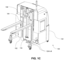
- FIGS. 1A through 1C depict an exemplary adjustable counterweight-based fork type autonomous mobile robot (ACFTAMR) 100, in accordance with an embodiment of the present disclosure. More specifically, FIGS. 1A through 1C , depict a perspective view of the adjustable counterweight-based fork type autonomous mobile robot (ACFTAMR) 100, in accordance with an embodiment of the present disclosure.
- the adjustable counterweight-based fork type autonomous mobile robot (ACFTAMR) may also be referred as 'apparatus', AMR, and may be interchangeably used herein.
- the ACFTAMR 100 comprises a chassis assembly 102, and a mast unit 104.
- the chassis assembly 102 is configured to hold the mast unit 104.
- the mast unit 104 is held by the chassis assembly 102.
- the chassis assembly 102 is configured to serve as a base part on which all other subunits/components of the ACFTAMR 100 are mounted.
- the chassis assembly 102 consists of four pathways in which plurality of bearings are mounted from both the sides of the holes. These pathways are configured to provide support to a plurality of counterbalance shafts.
- the chassis assembly 102 is a C type chassis assembly in an embodiment of the present disclosure.
- the chassis assembly 102 is provided with plurality of ribs for providing rigidness in the part/components of the ACFTAMR 100 and to avoid the buckling.
- the mast unit 104 comprises a fork mount 106 having a first end 108A and a second end 108B.
- the fork mount 106 is configured to accommodate a plurality of forks 110A-B using a plurality of fasteners 112A-N at each of the first end (108A) and the second end (108A).
- the mast unit 104 further comprises a first vertical plate 114A and a second vertical plate 114B.
- the mast unit 104 further comprises a first set of Liner Motion (LM) rails 116A-B wherein the first set of Liner Motion (LM) rails 116A-B is mounted on the first vertical plate 114A and the second vertical plate 114B respectively.
- LM Liner Motion
- first LM rail 116A of the first set of Liner Motion (LM) rails 116A-B is mounted on the first vertical plate 114A and the second LM rail 116B of the first set of Liner Motion (LM) rails 116A-B is mounted on the second vertical plate 114B.
- first LM rail 116A of the first set of Liner Motion (LM) rails 116A-B is mounted on the first vertical plate 114A and the second LM rail 116B of the first set of Liner Motion (LM) rails 116A-B is mounted on the second vertical plate 114B.
- the mast unit 104 further comprises a vertical lead screw mechanism 118 having a first end 120A and a second end 120B.
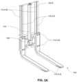
- the vertical lead screw mechanism 118 is equidistantly positioned between the first vertical plate 114A) and the second vertical plate 114B as shown in FIG. 2 .
- FIG. 2 depicts the mast unit 104 comprised in the ACFTAMR 100, in accordance with an embodiment of the present disclosure.
- the first end 120A of the vertical lead screw mechanism 120A is connected to the fork mount 106.
- the vertical lead screw mechanism 118 is configured to drive the fork mount 106 in at least one of a first direction, and a second direction.
- the first direction is a downward direction
- the second direction is an upward direction, in an embodiment of the present disclosure.
- Such movement of the fork mount 106 in either directions is achieved when the vertical lead screw mechanism 118 is moved in the downward or upward direction during a specific operation along with the first set of LM rails 116A-B, wherein the vertical lead screw mechanism 118 is operated to move in either directions, and driven by a corresponding motor (not shown in FIGS.).
- the ACFTAMR 100 further comprises a counterweight assembly 122 wherein the counterweight assembly 122 comprises a counterweight 123 comprising a first end 124A and a second end 124B.
- Each of the first end 124A and the second end 124B of the counterweight assembly 122 comprises a plurality of cutouts 126A-N.
- the counterweight assembly 122 comprises a first pair of counterbalance shafts 128A-B and a second pair of counterbalance shafts 128C-D.
- the first pair of counterbalance shafts 128A-B and the second pair of counterbalance shafts 128C-D are fitted on either side of the chassis assembly 102.
- Each counterbalance shaft from the first pair and the second pair of counterbalance shafts 128A-D comprises a corresponding flange 130A-D.
- the counterbalance shaft 128A comprises a flange 130A and the counterbalance shaft 128B comprises a flange 130B.
- the counterbalance shaft 128C comprises a flange 130C and the counterbalance shaft 128D comprises a flange 130D.
- Each corresponding cutout from the plurality of cutouts 126A-N is configured to accommodate the corresponding flange 128A-D.
- a cutout 126A which is part of the chassis assembly 102 is configured to accommodate the flange 128A
- a cutout 126B is configured to accommodate the flange 128B.
- cutouts 126C-N are configured to accommodate the flanges 128C and 128N respectively.
- FIG. 3A-3B depicts a rear perspective view of the ACFTAMR 100 with the counterweight assembly in an expanded and collapse position respectively, in accordance with an embodiment of the present disclosure. More specifically, FIG. 3A depicts the ACFTAMR 100 illustrating counterbalance shafts (e.g., the first pair counterbalance shafts 128A-D) and the counterweight assembly 122 comprising the counterweight 123 having the first end 124A and the second end 124B, wherein the counterweight assembly 122 is in a collapsed position, in accordance with an embodiment of the present disclosure. More specifically, FIG.
- counterbalance shafts e.g., the first pair counterbalance shafts 128A-D
- the counterweight assembly 122 comprising the counterweight 123 having the first end 124A and the second end 124B, wherein the counterweight assembly 122 is in a collapsed position, in accordance with an embodiment of the present disclosure. More specifically, FIG.
- FIG. 3B depicts the ACFTAMR 100 illustrating counterbalance shafts (e.g., the first pair counterbalance shafts 128A-D) and the counterweight assembly 122 comprising the counterweight 123 having the first end 124A and the second end 124B, wherein the counterweight assembly 122 is in an expanded position, in accordance with an embodiment of the present disclosure.
- FIG. 4A depicts a cross sectional view of the ACFTAMR 100, in accordance with an embodiment of the present disclosure. More specifically, FIG.
- FIG. 4A depicts a cross sectional view of the ACFTAMR illustrating the plurality of cutouts 126A-N and flanges 128A-D, represented within a broken line circle, in accordance with an embodiment of the present disclosure.
- FIG. 4B depicts a detailed view of the plurality of cutouts 126A-N and flanges 128A-D of the ACFTAMR 100 comprised in the broken line circle, in accordance with an embodiment of the present disclosure.
- the first pair and the second pair of counterbalance shafts 128A-D are configured to change from a first position to a second position (e.g., from collapsed position to expanded position as shown in FIG.
- each of the plurality of forks 110A-B is configured to slide through a corresponding fork assembly receiver of the payload (the receiver of the payload is not shown in FIGS.), and (iii) the fork mount 106 is driven from the first direction (e.g., downward direction) to the second direction (e.g., upward direction) via the first set of Liner Motion (LM) rails 116A-B, for lifting the payload by the plurality of forks 110A-B.
- LM Liner Motion
- Direction of fork mount 106 driven from the first direction (e.g., downward direction) to the second direction (e.g., upward direction) is depicted in FIG. 1C .
- This can also be realized in FIG. 2B , wherein the fork mount 106 is moved at the top or upward direction.
- the first pair and the second pair of counterbalance shafts 126A-D are configured to change from the second position (e.g., from expanded position) to the first position (e.g., to collapse position) and the ACFTAMR 100 is operated for navigation to a desired location.
- the change of expanded position to collapsed position of the shafts is depicted in FIG. 3A .
- One or more sensors/cameras as known in the art may be mounted on the ACFTAMR 100 to help navigate and detecting the payload and corresponding fork assembly receiver of the payload. Once detected, the pickup operation as described above is performed by the ACFTAMR 100.
- the first pair and the second pair of counterbalance shafts 128A-D are configured to change from the first position to the second position, and (ii) the fork mount 106 is driven from the second direction to the first direction.
- Such movement is depicted in FIGS. 1A and 1B . This can also be realized in FIG. 2A where the fork mount is at an initial/downward direction.
- the ACFTAMR 100 further comprises a steer and drive unit 132.
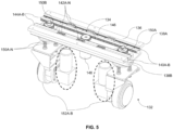
- FIG. 5 depicts the steer and drive unit comprised in the ACFTAMR 100, in accordance with an embodiment of the present disclosure.
- the steer and drive unit 132 comprises a rack and pinion assembly 134 which includes a mounting block 136.
- the mounting block 136 comprises a first side 138A and a second side 138B.
- the steer and drive unit 132 further comprises a second set of LM rails 140A-B. Each LM rail from the second set of LM rails 140A-B is mounted on an inner surface of the first side 138A and the second side 138B of the mounting block 136 respectively.
- the LM rail 140A is mounted on an inner surface of the first side 138A and the LM rail 140B is mounted on an inner surface of the second side 138B.
- the steer and drive unit 132 further comprises a plurality of LM blocks 142A-B. Each LM block from the plurality of LM blocks 142A-B is configured to slide on a corresponding LM rail from the second set of LM rails 140A-B.
- a first LM block say 142A (also referred as LM block and interchangeably used herein) is configured to slide on the LM rail 140A and the second LM block say 142B (also referred as LM block and interchangeably used herein) is configured to slide on the LM rail 140B, in an embodiment of the present disclosure.
- the steer and drive unit 132 further comprises a first rack 144A and a second rack 144B mounted on a corresponding LM block.
- the first rack 144A is mounted on the LM block 142A and the second rack is mounted on the LM block 142B.
- the steer and drive unit 132 further comprises a driver pinion 146.
- the driver pinion 146 is positioned at the center and in between the first rack 144A and the second rack 144B (e.g., refer FIG. 5 for position of the driver pinion 146) and is driven is by a motor 148.
- the steer and drive unit 132 further comprises a first driven pinion 150A and a second driven pinion 150B.
- the first driven pinion 150A and the second driven pinion 150B are positioned in between the first rack 144A and the second rack 144B such that the first driven pinion 150A and the second driven pinion 150B are on either side of the driver pinion 146.
- the first driven pinion 150A is at one side of the driven pinion 146 and the second driven pinion 150B is at another side of the driven pinion 146 as shown in FIG. 5 .
- the motor 148 is configured to (i) rotate the driver pinion 146, the first driven pinion 150A and the second driven pinion 150B in at least one direction, (ii) enable a plurality of drive wheels 152A-B attached to the first driven pinion 150A and the second driven pinion 152B to rotate in the at least one direction.
- the at least one direction is one of a clockwise direction or an anti-clockwise direction.
- the motor 148 rotates the driver pinion 146, the first driven pinion 150A and the second driven pinion 150B in a clockwise direction then the plurality of drive wheels 152A-B attached to the first driven pinion 150A and the second driven pinion 152B also rotate in the same clockwise direction.
- the motor 148 rotates the driver pinion 146, the first driven pinion 150A and the second driven pinion 150B in an anti-clockwise direction then the plurality of drive wheels 152A-B attached to the first driven pinion 150A and the second driven pinion 152B also rotate in the same anti-clockwise direction.
- each of the plurality of drive wheels 152A-B may be controlled and operated by a corresponding motor attached therein as depicted in FIG. 5 .
- the corresponding motor operatively attached/connected to each of the plurality of drive wheels 152A-B is shown within an oval shaped broken line representation. It is to be understood by a person having ordinary skill in the art or person skilled in the art that though there are 2 motors shown for operating the 2 drive wheels, such arrangement shall not be construed as limiting the scope of the present disclosure. In other words, only 1 motor may be configured or operatively coupled to both the drive wheels and accordingly driven for operation/navigation and rotation.
- the steer and drive unit 132 further comprises a plurality of suspension units 154A-N.
- Each suspension unit from the plurality of suspension units 154A-N is configured to provide suspension for the plurality of drive wheels 152A-B during navigation of the ACFTAMR 100.
- the plurality of suspension units 154A-N are provided on both sides of the steer and drive unit 132 where they are mounted on a plate which are positioned above the drive wheels 152A-B.
- the plurality of suspension units 154A-N still provide suspension for the plurality of drive wheels 152A-B (e.g., during a standstill condition) thus enabling better stability and balance.
- the above components and their configuration and functionalities may be better understood by the following illustrative description.
- the driver pinion 146 rotates and transmits motion to one or more racks 144A-B mounted on the LM blocks 142A-B and the LM rails 140A-B. These racks 144A-B further drive two set of driven pinions 150A-B mounted on a suspension shaft coupled to shaft support and mounted on the mounting block 136. These two sets of suspension shaft form a plurality of suspension units to which the plurality of drive wheels unit is mounted from the bottom.
- the suspension units are suspension springs which are in between the LM blocks and the drive wheel unit, and thus are enable isolation of the drive wheel unit from the chassis assembly thereby providing independent suspension to each drive wheel.
- Rotation of the driven pinion enables rotation of drive wheels thus forming steering of the ACFTAMR 100 for navigation.
- the drive wheels can rotate +/-90 degree. Such rotation shall not be construed as limiting the scope of the present disclosure.
- ACFTAMR 100 can move in either direction (e.g., forward, backward, sidewise, curved path, and the like).
- the drive wheels also provide traction to the ACFTAMR 100, in an embodiment of the present disclosure.
- the ACFTAMR 100 further comprises a battery unit 156 mounted on the chassis assembly 102.
- the battery unit 156 is configured to accommodate a battery 154 for providing power to the adjustable counterweight-based fork type autonomous mobile robot (ACFTAMR) 100.
- ACFTAMR adjustable counterweight-based fork type autonomous mobile robot
- the battery unit 156 comprises a plurality of stand-offs 158A-D. Each stand-off comprises a first end 160A and a second end 160B. The first end 160A of each stand-off is connected to a corresponding corner point of the battery unit 156.
- the battery unit 156 further comprises a first support link 162A connected to the second end 160B of a first stand-off 158A and a second stand-off 158B of the plurality of stand-offs 158A-D.
- a second support link 162B is connected to the second end 160B of a third stand-off 158C and a fourth stand-off 158D of the plurality of stand-offs 158A-D.
- the battery unit 156 further comprises a first L-shaped guide 164A and a second L-shaped guide 164B.
- Each of the first L-shaped guide 164A and the second L-shaped comprise 164B comprises a first end 166A and a second end 166B.
- the first end 166A of the first L-shaped guide 164A and the second L-shaped 164B is fixed to a corresponding corner plate mounted on the chassis assembly 102.
- the battery unit 156 further comprises a sliding door 168 that is operated by a positioning actuator 170.
- the battery unit 156 further comprises a first battery aligning component 172A and a second battery aligning component 172B.
- Each of the first battery aligning component 172A and the second battery aligning component 172B comprising a first portion 174A and a second portion 174B.
- the first portion 174A of the first battery aligning component 172A and the second battery aligning component 172B is connected to the first stand-off 158A and the third stand-off 158C respectively.
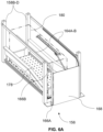
- FIGS. 6A and 6B depict the battery unit 156 comprised in the ACFTAMR 100, in accordance with an embodiment of the present disclosure. More specifically, FIG.
- FIG. 6A depicts the battery unit 156 with the sliding door 168 in a closed position, in accordance with an embodiment of the present disclosure.
- FIG. 6A depicts 156 battery unit comprised in the ACFTAMR 100 illustrating the sliding door 168 in a closed position, in accordance with an embodiment of the present disclosure.
- FIG. 6B depicts the battery unit 156 with the sliding door 168 in an open closed position, in accordance with an embodiment of the present disclosure.
- FIG. 6A depicts the battery unit 156 comprised in the ACFTAMR 100 illustrating the sliding door 168 in an open position, in accordance with an embodiment of the present disclosure.
- the battery unit 156 further comprises a plurality of telescopic rails 176A-B wherein each of the plurality of telescopic rails is connected to the chassis assembly 102.
- the battery unit 156 further comprises a ball plate 178 that is mounted on the plurality of telescopic rails 176A-B connected to the chassis assembly 102.
- Each of the plurality of telescopic rails 176A-B is configured to provide a guided pathway for the ball plate 178 to enable a battery 180 to slide inside or outside of the battery unit 156 via the formed tapered area.
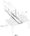
- FIG. 7 with reference to FIGS. 1A through 6B , FIG.
- the sliding door 168 is configured to (i) slide through the first L-shaped guide 164A and the second L-shaped 164B for open and close of the battery unit 156.
- the sliding door 168 serves as a shutter for replacement of the battery 156 or for performing any maintenance being identified.
- the ACFTAMR 100 further comprises a plurality of swivel wheels at the bottom for enabling navigation during the operation of the apparatus.
- Such functionalities of the swivel wheels can be realized as known in the art.
- each swivel wheel from the plurality of swivel wheels is further configured to enable forward and backward movement of the counterbalance shafts in a smooth manner. For instance, as depicted in FIGS. 1A through 1C and FIGS. 3A and 3B , there are 4 swivel wheels are realized and implemented by the ACFTAMR 100.
- the ACFTAMR 100 may further comprise a plate/connecting means like component which enables the swivel wheels to connect with corresponding ends of the corresponding countershafts and at bottom end/side of the counterweight assembly or the counterweight itself. Additionally, the ACFTAMR 100 may comprises a sensor feedback for controlled movement of the one or more corresponding components to lift a payload placed on a pallet.
- the ACFTAMR 100 are further equipped with contact and vision sensors that enable the ACFTAMR 100 to determine whether there is any offset or any contact between surfaces of the ACFTAMR 100 and the pallet. With the help of vision sensors, the forks capture image data (or sensor data) of object(s) (e.g., surrounding object(s) during navigation, size of payload, and pallet, etc.).
- Such sensor data can be in the form of 2-dimensional (2D) sensor data and/or 3-dimensional (3D) sensor data that is captured from a distance.
- the captured sensor data enables the ACFTAMR 100 to correct its offset and/or compute a mode of approach to handle the payload.
- the mode of approach for instance, shall include, navigating angle, sliding through pallet/roller cages, and the like.
- ACFTAMR Adjustable Counterweight-based Fork Type Autonomous Mobile Robot
- the chassis assembly as comprised in the apparatus 100 has front counterweight chassis and main chassis interconnected with sliding mechanism.
- the front counterweight chassis has a set of swivel wheels and at bottom has two extended arms towards the rear on either side. The rear ends of these two extended arms have additional swivel counterbalance wheels.
- the main chassis contains two differential drive wheels.
- the rear side of the main chassis is mounted with vertical mast (or the mast unit) and has a unique bridge connection to have a cross slide mechanism.
- each arm of the cross-slide unit contains individual fork arrangement (e.g., refer forks as depicted in FIGS.).
- bare vehicle or loaded apparatus 100 When bare vehicle or loaded apparatus 100 is traveling it achieves compactness in terms of the chassis assembly wherein during maneuvering of the apparatus 100 is compact and when lifting the pallet/payload with stringer in bottom. Further the apparatus 100 enables the chassis assembly and the counterweight assembly to move apart for providing sufficient balance and stability for pickup and release of the payload to a desired location.
- the apparatus/ACFTAMR 100 of the present disclosure/application has the two drive wheels as depicted in FIGS and without steering in action these two drive wheels can work as differential drive (wherein one of the drive wheels can move forward direction and another drive wheel can move in backward direction to create a zero (0) turning radius) and are able to rotate about the center.
- differential drive wherein one of the drive wheels can move forward direction and another drive wheel can move in backward direction to create a zero (0) turning radius
- the apparatus 100 can move cross wise.
- the apparatus 100 can move in that specific angular direction. This level of flexibility gives better advantage of maneuverability to the ACFTAMR 100.
- Such computer-readable storage means contain program-code means for implementation of one or more steps of the method, when the program runs on a server or mobile device or any suitable programmable device.
- the hardware device can be any kind of device which can be programmed including e.g., any kind of computer like a server or a personal computer, or the like, or any combination thereof.
- the device may also include means which could be e.g., hardware means like e.g., an application-specific integrated circuit (ASIC), a field-programmable gate array (FPGA), or a combination of hardware and software means, e.g., an ASIC and an FPGA, or at least one microprocessor and at least one memory with software processing components located therein.
- the means can include both hardware means and software means.
- the method embodiments described herein could be implemented in hardware and software.
- the device may also include software means. Alternatively, the embodiments may be implemented on different hardware devices, e.g., using a plurality of CPUs.
- the embodiments herein can comprise hardware and software elements.
- the embodiments that are implemented in software include but are not limited to, firmware, resident software, microcode, etc.
- the functions performed by various components described herein may be implemented in other components or combinations of other components.
- a computer-usable or computer readable medium can be any apparatus that can comprise, store, communicate, propagate, or transport the program for use by or in connection with the instruction execution system, apparatus, or device.
- a computer-readable storage medium refers to any type of physical memory on which information or data readable by a processor may be stored.
- a computer-readable storage medium may store instructions for execution by one or more processors, including instructions for causing the processor(s) to perform steps or stages consistent with the embodiments described herein.
- the term "computer-readable medium” should be understood to include tangible items and exclude carrier waves and transient signals, i.e., be non-transitory. Examples include random access memory (RAM), read-only memory (ROM), volatile memory, nonvolatile memory, hard drives, CD ROMs, DVDs, flash drives, disks, and any other known physical storage media.
Landscapes
- Engineering & Computer Science (AREA)
- Transportation (AREA)
- Structural Engineering (AREA)
- Civil Engineering (AREA)
- Life Sciences & Earth Sciences (AREA)
- Geology (AREA)
- Mechanical Engineering (AREA)
- Forklifts And Lifting Vehicles (AREA)
Claims (8)
- Verstellbarer gabelbasierter autonomer mobiler Roboter (ACFTAMR) (100) vom Gegengewichtstyp, umfassend:eine Fahrgestellanordnung (102);eine Masteinheit (104), die von der Fahrgestellanordnung (102) gehalten wird, wobei die Masteinheit (104) umfasst:eine Gabelhalterung (106), die ein erstes Ende (108A) und ein zweites Ende (108B) umfasst, wobei die Gabelhalterung (106) konfiguriert ist, um eine Mehrzahl von Gabeln (110A-B) unter Verwendung einer Mehrzahl von Befestigungsmitteln (112A-N) an jedem von dem ersten Ende (108A) und dem zweiten Ende (108B) aufzunehmen;eine erste vertikale Platte (114A) und eine zweite vertikale Platte (114B);einen ersten Satz von Liner-Motion (LM)-Schienen (116A-B), die jeweils an der ersten vertikalen Platte (114A) und der zweiten vertikalen Platte (114B) montiert sind; undeinen vertikalen Leitspindelmechanismus (118), der ein erstes Ende (120A) und ein zweites Ende (120B) umfasst, wobei das erste Ende (120A) des vertikalen Leitspindelmechanismus (120A) mit der Gabelhalterung (106) verbunden ist, und wobei der vertikale Leitspindelmechanismus (118) konfiguriert ist, um die Gabelhalterung (106) in mindestens eine von einer ersten Richtung und einer zweiten Richtung anzutreiben;eine Gegengewichtanordnung (122), die ein erstes Ende (124A) und ein zweites Ende (124B) umfasst, wobei jedes von dem ersten Ende (124A) und dem zweiten Ende (124B) der Gegengewichtanordnung (122) eine Mehrzahl von Ausschnitten (126A-N) umfasst, wobei die Gegengewichtanordnung (122) umfasst:ein erstes Paar von Gegengewichtswellen (128A-B) und ein zweites Paar von Gegengewichtswellen (128C-D), wobei jede Gegengewichtswelle von dem ersten Paar und dem zweiten Paar von Gegengewichtswellen (128A-D) einen entsprechenden Flansch (130A-D) umfasst, wobei jeder entsprechende Ausschnitt von der Mehrzahl von Ausschnitten (126A-N) konfiguriert ist, um den entsprechenden Flansch (130A-D) aufzunehmen,wobei während einer Aufnahme einer Nutzlast durch die Mehrzahl von Gabeln (110A-B) (i) das erste Paar und das zweite Paar von Gegengewichtswellen (128A-D) konfiguriert sind, um von einer ersten Position in eine zweite Position zu wechseln, (ii) nachdem die Mehrzahl von dem ersten Paar und dem zweiten Paar von Gegengewichtswellen (128A-D) von der ersten Position in die zweite Position wechselt, jede der Mehrzahl von Gabeln (110A-B) konfiguriert ist, um durch eine entsprechende Gabelanordnungsaufnahme der Nutzlast zu gleiten, und (iii) die Gabelhalterung (106) von der ersten Richtung in die zweite Richtung über den ersten Satz von Liner-Motion (LM)-Schienen (116A-B) angetrieben wird, um die Nutzlast durch die Mehrzahl von Gabeln anzuheben, undwobei nach dem Anheben der Nutzlast auf der Mehrzahl von Gabeln (110A-B) das erste Paar und das zweite Paar von Gegengewichtswellen (128A-D) konfiguriert sind, um von der zweiten Position in die erste Position zu wechseln, und die ACFTAMR zur Navigation zu einem gewünschten Ort betrieben wird.
- Verstellbarer gabelbasierter autonomer mobiler Roboter (ACFTAMR) vom Gegengewichtstyp nach Anspruch 1, wobei der vertikale Leitspindelmechanismus (118) in gleichem Abstand zwischen der ersten vertikalen Platte (114A) und der zweiten vertikalen Platte (114B) positioniert ist.
- Verstellbarer gabelbasierter autonomer mobiler Roboter (ACFTAMR) vom Gegengewichtstyp nach Anspruch 1, wobei, wenn die Nutzlast von der Mehrzahl von Gabeln (110A-B) an den gewünschten Ort freigegeben werden soll, (i) das erste Paar und das zweite Paar von Gegengewichtswellen (128A-D) konfiguriert sind, um von der ersten Position in die zweite Position zu wechseln, und (ii) die Gabelhalterung (106) von der zweiten Richtung in die erste Richtung angetrieben wird.
- Verstellbarer gabelbasierter autonomer mobiler Roboter (ACFTAMR) vom Gegengewichtstyp nach Anspruch 1, ferner umfassend eine Lenk- und Antriebseinheit (132), umfassend:
eine Zahnstangenanordnung (134), umfassend:einen Montageblock (136) mit einer ersten Seite (138A) und einer zweiten Seite (138B);einen zweiten Satz von LM-Schienen (140A-B), wobei jede LM-Schiene des zweiten Satzes von LM-Schienen (140A-B) jeweils an einer Innenfläche der ersten Seite (138A) und der zweiten Seite (138B) montiert ist;eine Mehrzahl von LM-Blöcken (142A-B), wobei jeder LM-Block aus der Mehrzahl von LM-Blöcken (142A-B) konfiguriert ist, um auf einer entsprechenden LM-Schiene aus dem zweiten Satz von LM-Schienen (140AB) zu gleiten;eine erste Zahnstange (144A) und eine zweite Zahnstange (144B), die an einem entsprechenden LM-Block montiert sind;ein Antriebsritzel (146), das in der Mitte und zwischen der ersten Zahnstange (144A) und der zweiten Zahnstange (144B) positioniert ist und durch einen Motor (148) angetrieben wird; undein erstes angetriebenes Ritzel (150A) und ein zweites angetriebenes Ritzel (150B), wobei jedes von dem ersten angetriebenen Ritzel (150A) und dem zweiten angetriebenen Ritzel (150B) zwischen der ersten Zahnstange (144A) und der zweiten Zahnstange (144A) positioniert ist, sodass sich das erste angetriebene Ritzel (150A) und das zweite angetriebene Ritzel (150B) auf jeder Seite des Antriebsritzels (146) befinden. - Verstellbarer gabelbasierter autonomer mobiler Roboter (ACFTAMR) vom Gegengewichtstyp nach Anspruch 4, wobei der Motor (148) konfiguriert ist, um (i) das Antriebsritzel (146), das erste angetriebene Ritzel (150A) und das zweite angetriebene Ritzel (150B) in mindestens eine Richtung zu drehen, (ii) es einer Mehrzahl von Antriebsrädern (152A-B), die an dem ersten angetriebenen Ritzel (150A) und dem zweiten angetriebenen Ritzel (150B) befestigt sind, zu ermöglichen, sich in die mindestens eine Richtung zu drehen.
- Verstellbarer gabelbasierter autonomer mobiler Roboter (ACFTAMR) vom Gegengewichtstyp nach Anspruch 5, wobei die Lenk- und Antriebseinheit (132) ferner umfasst
eine Mehrzahl von Aufhängungseinheiten (154A-N), wobei jede Aufhängungseinheit aus der Mehrzahl von Aufhängungseinheiten (154A-N) konfiguriert ist, um eine Aufhängung für die Mehrzahl von Antriebsrädern (152A-B) während der Navigation der ACFTAMR bereitzustellen. - Verstellbarer gabelbasierter autonomer mobiler Roboter (ACFTAMR) vom Gegengewichtstyp nach Anspruch 1, ferner umfassend:
eine Batterieeinheit (156), die an der Fahrgestellanordnung (102) montiert ist, wobei die Batterieeinheit (156) konfiguriert ist, um eine Batterie (180) zum Bereitstellen von Leistung für den verstellbaren gabelbasierten autonomen mobilen Roboter (ACFTAMR) vom Gegengewichtstyp aufzunehmen, und wobei die Batterieeinheit (156) umfasst:eine Mehrzahl von Abstandshaltern (158A-D), wobei jeder Abstandshalter ein erstes Ende (160A) und ein zweites Ende (160B) umfasst, wobei das erste Ende (160A) jedes Abstandshalters mit einem entsprechenden Eckpunkt der Batterieeinheit (156) verbunden ist;ein erstes Stützglied (162A), das mit dem zweiten Ende (160B) eines ersten Abstandshalters (158A) und eines zweiten Abstandshalters (158B) der Mehrzahl von Abstandshaltern (158A-D) verbunden ist;ein zweites Stützglied (162B), das mit dem zweiten Ende (160B) eines dritten Abstandshalters (158C) und eines vierten Abstandshalters (158D) der Mehrzahl von Abstandshaltern (158A-D) verbunden ist;eine erste L-förmige Führung (164A) und eine zweite L-förmige Führung (164B), wobei jede der ersten L-förmigen Führung (164A) und der zweiten L-förmigen Führung (164B) ein erstes Ende (166A) und ein zweites Ende (166B) umfasst, wobei das erste Ende (166A) der ersten L-förmigen Führung (164A) und der zweiten L-förmigen Führung (164B) an einer entsprechenden Eckplatte befestigt ist, die an der Fahrgestellanordnung (102) montiert ist;eine Schiebetür (168), die durch einen Positionierungsaktuator (170) betrieben wird, wobei die Schiebetür (168) konfiguriert ist, um (i) durch die erste L-förmige Führung (164A) und die zweite L-förmige Führung (164B) zum Öffnen und Schließen der Batterieeinheit (156) zu gleiten; undeine erste Batterieausrichtungskomponente (172A) und eine zweite Batterieausrichtungskomponente (172B), wobei jede der ersten Batterieausrichtungskomponente (172A) und der zweiten Batterieausrichtungskomponente (172B) einen ersten Abschnitt (174A) und einen zweiten Abschnitt (174B) umfasst,wobei der erste Abschnitt (174A) der ersten Batterieausrichtungskomponente (172A) und der zweiten Batterieausrichtungskomponente (172B) jeweils mit dem ersten Abstandshalter (158A) und dem dritten Abstandshalter (158C) verbunden ist, undwobei der zweite Abschnitt (174B) der ersten Batterieausrichtungskomponente (172A) und der zweiten Batterieausrichtungskomponente (172B) mit dem zweiten Abstandshalter (158B) und dem vierten Abstandshalter (158D) verbunden ist, um einen verjüngten Bereich zu bilden. - Verstellbarer gabelbasierter autonomer mobiler Roboter (ACFTAMR) vom Gegengewichtstyp nach Anspruch 6, wobei die Batterieeinheit (156) ferner umfasst:eine Mehrzahl von Teleskopschienen (176A-B), die mit der Fahrgestellanordnung (102) verbunden sind; undeine Kugelplatte (178), die an der Mehrzahl von Teleskopschienen (176A-B) montiert ist, die mit der Fahrgestellanordnung (102) verbunden sind, wobei jede der Mehrzahl von Teleskopschienen (176A-B) konfiguriert ist, um einen geführten Weg für die Kugelplatte (178) bereitzustellen, um der Batterie (180) zu ermöglichen, über den gebildeten verjüngten Bereich innerhalb oder außerhalb der Batterieeinheit (156) zu gleiten.
Applications Claiming Priority (1)
| Application Number | Priority Date | Filing Date | Title |
|---|---|---|---|
| IN202221000369 | 2022-01-04 |
Publications (3)
| Publication Number | Publication Date |
|---|---|
| EP4206115A1 EP4206115A1 (de) | 2023-07-05 |
| EP4206115C0 EP4206115C0 (de) | 2024-07-24 |
| EP4206115B1 true EP4206115B1 (de) | 2024-07-24 |
Family
ID=82742910
Family Applications (1)
| Application Number | Title | Priority Date | Filing Date |
|---|---|---|---|
| EP22186966.2A Active EP4206115B1 (de) | 2022-01-04 | 2022-07-26 | Autonomer mobiler roboter mit einer verstellbaren gegengewicht und einer gabelstapler vorrichtung |
Country Status (2)
| Country | Link |
|---|---|
| US (1) | US11905152B2 (de) |
| EP (1) | EP4206115B1 (de) |
Families Citing this family (3)
| Publication number | Priority date | Publication date | Assignee | Title |
|---|---|---|---|---|
| EP3800113B1 (de) * | 2019-10-01 | 2024-03-06 | Mobile Industrial Robots A/S | Mobiler roboter mit einstellbaren traktionsgewichten |
| IT202400001437A1 (it) * | 2024-01-25 | 2025-07-25 | Toyota Mat Handling Manufacturing Italy S P A | Carrello industriale con uno sportello del vano batteria migliorato |
| CN121376874B (zh) * | 2025-12-26 | 2026-03-17 | 泰兴市华诚机电制造有限公司 | 一种基于无人搬运车的自动取货卸货设备 |
Family Cites Families (28)
| Publication number | Priority date | Publication date | Assignee | Title |
|---|---|---|---|---|
| US2693250A (en) * | 1951-08-25 | 1954-11-02 | Barrett Cravens Co | Fork truck having adjustable counterweight |
| US2759563A (en) * | 1952-09-13 | 1956-08-21 | Marnon | Adjustable counterweight for lift vehicles |
| US3687484A (en) * | 1970-05-05 | 1972-08-29 | Clark Equipment Co | Lift truck with overhead guard and counterweight |
| US3734326A (en) * | 1971-07-15 | 1973-05-22 | Eaton Corp | Variable capacity lift truck |
| US4221530A (en) * | 1978-06-08 | 1980-09-09 | Williams Iv James M | Force-moment compensating apparatus |
| JPH0812288A (ja) * | 1994-06-24 | 1996-01-16 | Meidensha Corp | 昇降装置及び該昇降装置を有する無人搬送車 |
| GB2355244A (en) * | 1999-08-05 | 2001-04-18 | Terence Harley | Fork-lift truck auto-balancing system |
| DE102006060325A1 (de) | 2006-12-20 | 2008-06-26 | Linde Material Handling Gmbh | Flurförderzeug mit einem horizontal entnehmbaren Batterieblock auf einer blattförmigen Ladeeinheit |
| KR101552554B1 (ko) * | 2014-03-14 | 2015-09-14 | 힘찬산업기계 주식회사 | 중장비용 카운트웨이트 리프트장치 |
| US10953555B2 (en) | 2016-10-14 | 2021-03-23 | IAM Robotics, LLC | Field replaceable battery pack and lift counterbalance for a mobile manipulation robot |
| CN107188086A (zh) * | 2017-05-18 | 2017-09-22 | 安徽宇锋仓储设备有限公司 | 自动控制平衡叉车 |
| CN107757751B (zh) | 2017-11-17 | 2024-02-27 | 西安优艾智合机器人科技有限公司 | 一种轮式自主移动机器人 |
| CN108773799A (zh) * | 2018-08-28 | 2018-11-09 | 朱根妹 | 一种方便调节使用的叉车配重装置 |
| CN209306892U (zh) * | 2018-12-28 | 2019-08-27 | 中核(天津)机械有限公司 | 一种小型装卸设备 |
| JP7215948B2 (ja) * | 2019-03-28 | 2023-01-31 | 三菱重工業株式会社 | フォークリフト |
| KR102252870B1 (ko) * | 2019-04-12 | 2021-05-17 | 장진만 | 밸런스 조절이 가능한 농업용 지게차 |
| CN113086895A (zh) * | 2020-01-08 | 2021-07-09 | 浙江知嘛网络科技有限公司 | 一种重心可调节的叉车配重块 |
| CN111362194A (zh) * | 2020-04-09 | 2020-07-03 | 陈辰 | 一种可变距电动叉车 |
| US11383773B2 (en) * | 2020-06-29 | 2022-07-12 | Saudi Arabian Oil Company | Stability control for load transport vehicles |
| KR102394779B1 (ko) * | 2020-08-19 | 2022-05-04 | 현대제철 주식회사 | 지게차 |
| CN112499523A (zh) * | 2020-11-05 | 2021-03-16 | 鸿程电子工业(南通)有限公司 | 一种叉车 |
| CN112408269A (zh) * | 2020-11-19 | 2021-02-26 | 张达宇 | 一种电动平衡重叉车的控制系统的散热装置 |
| CN113803522A (zh) * | 2021-09-17 | 2021-12-17 | 江西应用技术职业学院 | 一种基于地质勘探用的管道自动对接装置及其使用方法 |
| CN113929024B (zh) * | 2021-11-01 | 2022-08-23 | 湖南速玖智能科技有限公司 | 一种无圆形方向盘的智能工程叉车 |
| CN114229737B (zh) * | 2021-12-28 | 2024-06-11 | 昆山紫东智能科技有限公司 | 一种物料升降料架 |
| CN115072627A (zh) * | 2022-06-12 | 2022-09-20 | 安徽金岩高岭土科技有限公司 | 一种免烧砖的自动叠板装置 |
| CN115180559B (zh) * | 2022-08-06 | 2023-08-01 | 浙江尤恩叉车股份有限公司 | Agv叉车稳定系统 |
| CN115520813B (zh) * | 2022-09-28 | 2025-06-24 | 浙江尤恩叉车股份有限公司 | 叉车配重结构 |
-
2022
- 2022-07-26 EP EP22186966.2A patent/EP4206115B1/de active Active
- 2022-07-28 US US17/815,755 patent/US11905152B2/en active Active
Also Published As
| Publication number | Publication date |
|---|---|
| EP4206115A1 (de) | 2023-07-05 |
| US20230211989A1 (en) | 2023-07-06 |
| US11905152B2 (en) | 2024-02-20 |
| EP4206115C0 (de) | 2024-07-24 |
Similar Documents
| Publication | Publication Date | Title |
|---|---|---|
| EP4206115A1 (de) | Autonomer mobiler roboter mit einer verstellbaren gegengewicht und einer gabelstapler vorrichtung | |
| US12291396B2 (en) | Method for controlling warehouse robot to store and fetch inventory materials | |
| KR102539465B1 (ko) | 서스펜션 모듈을 포함하는 이동 로봇 | |
| JP7175105B2 (ja) | 荷台搬送用ロボット | |
| EP4242138A1 (de) | Lagersystem mit geführter plattenbasierter hebevorrichtung zum laden und entladen von nutzlasten auf ein lagergestell | |
| CN113924265B (zh) | 自主全向驱动单元 | |
| US11745812B2 (en) | Running device | |
| JPH0428700A (ja) | プログラム制御による箱、コンテナ等の操作・移送装置 | |
| KR102017097B1 (ko) | 팔레트 반송 장치 | |
| CN119059131A (zh) | 搬运机器人、货架、仓储系统及对接方法 | |
| CN111591653A (zh) | 一种带独立位置补偿旋转平台的紧凑型agv及控制方法 | |
| CN116133930A (zh) | 轮臂式堆垛机,优选为agv | |
| EP4043385B1 (de) | Vorrichtung zur autonomen handhabung von nutzlasten | |
| US20230399065A1 (en) | Running Device | |
| EP4303094B1 (de) | Gabelanordnung für autonome mobile roboter und automatisierte geführte fahrzeuge | |
| WO2021117086A1 (ja) | 運搬車両 | |
| JP4946503B2 (ja) | ワーク取り出し装置 | |
| KR20220156384A (ko) | 무인 운반차의 바퀴 주행 장치 | |
| KR20190044899A (ko) | 전방향 주행 로봇 및 로봇의 주행 시스템 | |
| EP4563517A1 (de) | Bremsung eines mobilen roboters | |
| EP4151379B1 (de) | Kopf für eine brückenbearbeitungsmaschine | |
| CN121285267B (zh) | 一种晶圆承载装置 | |
| CN118144900A (zh) | 搬运设备 | |
| CN122035750A (zh) | 搬运机器人 | |
| WO2023223718A1 (ja) | 搬送装置、搬送制御システム、及び制御方法 |
Legal Events
| Date | Code | Title | Description |
|---|---|---|---|
| PUAI | Public reference made under article 153(3) epc to a published international application that has entered the european phase |
Free format text: ORIGINAL CODE: 0009012 |
|
| STAA | Information on the status of an ep patent application or granted ep patent |
Free format text: STATUS: REQUEST FOR EXAMINATION WAS MADE |
|
| 17P | Request for examination filed |
Effective date: 20230505 |
|
| AK | Designated contracting states |
Kind code of ref document: A1 Designated state(s): AL AT BE BG CH CY CZ DE DK EE ES FI FR GB GR HR HU IE IS IT LI LT LU LV MC MK MT NL NO PL PT RO RS SE SI SK SM TR |
|
| GRAP | Despatch of communication of intention to grant a patent |
Free format text: ORIGINAL CODE: EPIDOSNIGR1 |
|
| STAA | Information on the status of an ep patent application or granted ep patent |
Free format text: STATUS: GRANT OF PATENT IS INTENDED |
|
| INTG | Intention to grant announced |
Effective date: 20240213 |
|
| GRAS | Grant fee paid |
Free format text: ORIGINAL CODE: EPIDOSNIGR3 |
|
| GRAA | (expected) grant |
Free format text: ORIGINAL CODE: 0009210 |
|
| STAA | Information on the status of an ep patent application or granted ep patent |
Free format text: STATUS: THE PATENT HAS BEEN GRANTED |
|
| AK | Designated contracting states |
Kind code of ref document: B1 Designated state(s): AL AT BE BG CH CY CZ DE DK EE ES FI FR GB GR HR HU IE IS IT LI LT LU LV MC MK MT NL NO PL PT RO RS SE SI SK SM TR |
|
| REG | Reference to a national code |
Ref country code: GB Ref legal event code: FG4D |
|
| REG | Reference to a national code |
Ref country code: CH Ref legal event code: EP |
|
| REG | Reference to a national code |
Ref country code: DE Ref legal event code: R096 Ref document number: 602022004755 Country of ref document: DE |
|
| REG | Reference to a national code |
Ref country code: IE Ref legal event code: FG4D |
|
| U01 | Request for unitary effect filed |
Effective date: 20240724 |
|
| U07 | Unitary effect registered |
Designated state(s): AT BE BG DE DK EE FI FR IT LT LU LV MT NL PT SE SI Effective date: 20240730 |
|
| U20 | Renewal fee for the european patent with unitary effect paid |
Year of fee payment: 3 Effective date: 20240731 |
|
| PG25 | Lapsed in a contracting state [announced via postgrant information from national office to epo] |
Ref country code: NO Free format text: LAPSE BECAUSE OF FAILURE TO SUBMIT A TRANSLATION OF THE DESCRIPTION OR TO PAY THE FEE WITHIN THE PRESCRIBED TIME-LIMIT Effective date: 20241024 |
|
| PG25 | Lapsed in a contracting state [announced via postgrant information from national office to epo] |
Ref country code: PL Free format text: LAPSE BECAUSE OF FAILURE TO SUBMIT A TRANSLATION OF THE DESCRIPTION OR TO PAY THE FEE WITHIN THE PRESCRIBED TIME-LIMIT Effective date: 20240724 Ref country code: GR Free format text: LAPSE BECAUSE OF FAILURE TO SUBMIT A TRANSLATION OF THE DESCRIPTION OR TO PAY THE FEE WITHIN THE PRESCRIBED TIME-LIMIT Effective date: 20241025 |
|
| PG25 | Lapsed in a contracting state [announced via postgrant information from national office to epo] |
Ref country code: IS Free format text: LAPSE BECAUSE OF FAILURE TO SUBMIT A TRANSLATION OF THE DESCRIPTION OR TO PAY THE FEE WITHIN THE PRESCRIBED TIME-LIMIT Effective date: 20241124 |
|
| PG25 | Lapsed in a contracting state [announced via postgrant information from national office to epo] |
Ref country code: HR Free format text: LAPSE BECAUSE OF FAILURE TO SUBMIT A TRANSLATION OF THE DESCRIPTION OR TO PAY THE FEE WITHIN THE PRESCRIBED TIME-LIMIT Effective date: 20240724 |
|
| PG25 | Lapsed in a contracting state [announced via postgrant information from national office to epo] |
Ref country code: RS Free format text: LAPSE BECAUSE OF FAILURE TO SUBMIT A TRANSLATION OF THE DESCRIPTION OR TO PAY THE FEE WITHIN THE PRESCRIBED TIME-LIMIT Effective date: 20241024 Ref country code: ES Free format text: LAPSE BECAUSE OF FAILURE TO SUBMIT A TRANSLATION OF THE DESCRIPTION OR TO PAY THE FEE WITHIN THE PRESCRIBED TIME-LIMIT Effective date: 20240724 |
|
| PG25 | Lapsed in a contracting state [announced via postgrant information from national office to epo] |
Ref country code: RS Free format text: LAPSE BECAUSE OF FAILURE TO SUBMIT A TRANSLATION OF THE DESCRIPTION OR TO PAY THE FEE WITHIN THE PRESCRIBED TIME-LIMIT Effective date: 20241024 Ref country code: PL Free format text: LAPSE BECAUSE OF FAILURE TO SUBMIT A TRANSLATION OF THE DESCRIPTION OR TO PAY THE FEE WITHIN THE PRESCRIBED TIME-LIMIT Effective date: 20240724 Ref country code: NO Free format text: LAPSE BECAUSE OF FAILURE TO SUBMIT A TRANSLATION OF THE DESCRIPTION OR TO PAY THE FEE WITHIN THE PRESCRIBED TIME-LIMIT Effective date: 20241024 Ref country code: IS Free format text: LAPSE BECAUSE OF FAILURE TO SUBMIT A TRANSLATION OF THE DESCRIPTION OR TO PAY THE FEE WITHIN THE PRESCRIBED TIME-LIMIT Effective date: 20241124 Ref country code: HR Free format text: LAPSE BECAUSE OF FAILURE TO SUBMIT A TRANSLATION OF THE DESCRIPTION OR TO PAY THE FEE WITHIN THE PRESCRIBED TIME-LIMIT Effective date: 20240724 Ref country code: GR Free format text: LAPSE BECAUSE OF FAILURE TO SUBMIT A TRANSLATION OF THE DESCRIPTION OR TO PAY THE FEE WITHIN THE PRESCRIBED TIME-LIMIT Effective date: 20241025 Ref country code: ES Free format text: LAPSE BECAUSE OF FAILURE TO SUBMIT A TRANSLATION OF THE DESCRIPTION OR TO PAY THE FEE WITHIN THE PRESCRIBED TIME-LIMIT Effective date: 20240724 |
|
| PG25 | Lapsed in a contracting state [announced via postgrant information from national office to epo] |
Ref country code: SM Free format text: LAPSE BECAUSE OF FAILURE TO SUBMIT A TRANSLATION OF THE DESCRIPTION OR TO PAY THE FEE WITHIN THE PRESCRIBED TIME-LIMIT Effective date: 20240724 Ref country code: RO Free format text: LAPSE BECAUSE OF FAILURE TO SUBMIT A TRANSLATION OF THE DESCRIPTION OR TO PAY THE FEE WITHIN THE PRESCRIBED TIME-LIMIT Effective date: 20240724 |
|
| PG25 | Lapsed in a contracting state [announced via postgrant information from national office to epo] |
Ref country code: MC Free format text: LAPSE BECAUSE OF FAILURE TO SUBMIT A TRANSLATION OF THE DESCRIPTION OR TO PAY THE FEE WITHIN THE PRESCRIBED TIME-LIMIT Effective date: 20240724 |
|
| PG25 | Lapsed in a contracting state [announced via postgrant information from national office to epo] |
Ref country code: CZ Free format text: LAPSE BECAUSE OF FAILURE TO SUBMIT A TRANSLATION OF THE DESCRIPTION OR TO PAY THE FEE WITHIN THE PRESCRIBED TIME-LIMIT Effective date: 20240724 |
|
| PG25 | Lapsed in a contracting state [announced via postgrant information from national office to epo] |
Ref country code: SK Free format text: LAPSE BECAUSE OF FAILURE TO SUBMIT A TRANSLATION OF THE DESCRIPTION OR TO PAY THE FEE WITHIN THE PRESCRIBED TIME-LIMIT Effective date: 20240724 |
|
| PLBE | No opposition filed within time limit |
Free format text: ORIGINAL CODE: 0009261 |
|
| STAA | Information on the status of an ep patent application or granted ep patent |
Free format text: STATUS: NO OPPOSITION FILED WITHIN TIME LIMIT |
|
| 26N | No opposition filed |
Effective date: 20250425 |
|
| PG25 | Lapsed in a contracting state [announced via postgrant information from national office to epo] |
Ref country code: IE Free format text: LAPSE BECAUSE OF NON-PAYMENT OF DUE FEES Effective date: 20240726 |
|
| U20 | Renewal fee for the european patent with unitary effect paid |
Year of fee payment: 4 Effective date: 20250725 |
|
| PGFP | Annual fee paid to national office [announced via postgrant information from national office to epo] |
Ref country code: CH Payment date: 20250801 Year of fee payment: 4 |
|
| PG25 | Lapsed in a contracting state [announced via postgrant information from national office to epo] |
Ref country code: CY Free format text: LAPSE BECAUSE OF FAILURE TO SUBMIT A TRANSLATION OF THE DESCRIPTION OR TO PAY THE FEE WITHIN THE PRESCRIBED TIME-LIMIT; INVALID AB INITIO Effective date: 20220726 |
|
| PG25 | Lapsed in a contracting state [announced via postgrant information from national office to epo] |
Ref country code: HU Free format text: LAPSE BECAUSE OF FAILURE TO SUBMIT A TRANSLATION OF THE DESCRIPTION OR TO PAY THE FEE WITHIN THE PRESCRIBED TIME-LIMIT; INVALID AB INITIO Effective date: 20220726 |