EP4151379B1 - Kopf für eine brückenbearbeitungsmaschine - Google Patents
Kopf für eine brückenbearbeitungsmaschine Download PDFInfo
- Publication number
- EP4151379B1 EP4151379B1 EP22195038.9A EP22195038A EP4151379B1 EP 4151379 B1 EP4151379 B1 EP 4151379B1 EP 22195038 A EP22195038 A EP 22195038A EP 4151379 B1 EP4151379 B1 EP 4151379B1
- Authority
- EP
- European Patent Office
- Prior art keywords
- shaft
- tool holder
- head
- holder assembly
- base portion
- Prior art date
- Legal status (The legal status is an assumption and is not a legal conclusion. Google has not performed a legal analysis and makes no representation as to the accuracy of the status listed.)
- Active
Links
Images

Classifications
-
- B—PERFORMING OPERATIONS; TRANSPORTING
- B28—WORKING CEMENT, CLAY, OR STONE
- B28D—WORKING STONE OR STONE-LIKE MATERIALS
- B28D7/00—Accessories specially adapted for use with machines or devices of the preceding groups
- B28D7/04—Accessories specially adapted for use with machines or devices of the preceding groups for supporting or holding work or conveying or discharging work
- B28D7/043—Accessories specially adapted for use with machines or devices of the preceding groups for supporting or holding work or conveying or discharging work the supporting or holding device being angularly adjustable
-
- B—PERFORMING OPERATIONS; TRANSPORTING
- B28—WORKING CEMENT, CLAY, OR STONE
- B28D—WORKING STONE OR STONE-LIKE MATERIALS
- B28D1/00—Working stone or stone-like materials, e.g. brick, concrete or glass, not provided for elsewhere; Machines, devices, tools therefor
- B28D1/02—Working stone or stone-like materials, e.g. brick, concrete or glass, not provided for elsewhere; Machines, devices, tools therefor by sawing
- B28D1/04—Working stone or stone-like materials, e.g. brick, concrete or glass, not provided for elsewhere; Machines, devices, tools therefor by sawing with circular or cylindrical saw-blades or saw-discs
- B28D1/043—Gantry type sawing machines
-
- B—PERFORMING OPERATIONS; TRANSPORTING
- B28—WORKING CEMENT, CLAY, OR STONE
- B28D—WORKING STONE OR STONE-LIKE MATERIALS
- B28D7/00—Accessories specially adapted for use with machines or devices of the preceding groups
- B28D7/04—Accessories specially adapted for use with machines or devices of the preceding groups for supporting or holding work or conveying or discharging work
- B28D7/046—Accessories specially adapted for use with machines or devices of the preceding groups for supporting or holding work or conveying or discharging work the supporting or holding device being of the vacuum type
Definitions
- the present invention relates to a head for a bridge processing machine of the type specified in the preamble of claim 1.
- the present invention relates to a head for a processing machine, for example, for cutting, configured to allow the processing of blocks, plates or slabs of any material and, more specifically, stone material, such as marble, granite or other similar material.
- a head for a processing machine, for example, for cutting, configured to allow the processing of blocks, plates or slabs of any material and, more specifically, stone material, such as marble, granite or other similar material.
- the head allows plates of stone material to be processed.
- Bridge processing machines are currently known and, in particular, bridge machines intended for cutting.
- Bridge or portal cutting machines also known as bridge or portal cutting centers are apparatuses equipped with a work table, a support bridge, a moving member and a head comprising a tool holder assembly, for example, a cutter, a circular blade, a laser or other cutting device.
- the work table substantially defines the plane on which the objects to be cut are placed, for example, blocks, plates, slabs or other.
- the support bridge generally comprises a beam element loosely connected to side walls or also to structures resting on the ground, for example, provided with rails, on which the work head is loosely connected.
- the moving member therefore, allows the control of the relative movement between head and bridge and, moreover, also between bridge and walls or support structure.
- the movement of the head is allowed along a direction perpendicular to the direction of relative movement between the bridge and the walls or structure.
- the head may be easily carried into any position of the plane defined by the work table.
- the moving member may also be configured, and often it is, to also allow relative rotations between head and bridge.
- the head is also equipped with a support portion and a tool holder assembly.
- the support portion is substantially configured to be moved by the moving member, as previously explained.
- the tool holder assembly is loosely bound to the support portion, and configured to translate and rotate with respect to an axis perpendicular to the work surface as well as the relative direction of movement between head and bridge.
- Movement of the object on the work surface is generally obtained by means of overhead cranes or forklifts independent of the processing machine.
- Forklifts are, therefore, often equipped with gripping means, for example, suction cups, for gripping objects.
- gripping means for example, suction cups
- the gripping means may be part of a manipulator assembly loosely bound to the bridge and movable along a predetermined direction by means of an autonomous moving member.
- the gripping means are rotatable between an operating position, in which they are arranged in proximity to the work surface, and a non-operative position, in which they are substantially removed from the work surface. This characteristic allows using the same moving member for moving the tool and gripping means.
- control unit to control the positions of the tool holder assembly and the gripping means with respect to a single coordinate system, avoiding the correlation of different reference systems with obvious simplifications in the operation of the machine.
- a processing head is known from IT 2018 0002 0725 A1 .
- the processing head disclosed in this document has a tool holder assembly and a gripping unit having respective constraint means in the form of respective connecting flanges which are both rigidly connected in rotation to a wheel driven by the vertical shaft of the head (the shaft which is used to orient the tool around a vertical axis during a processing operation).
- both the tool holder assembly and the gripping unit are driven together by the above-mentioned vertical shaft of the processing head.
- this solution is relatively complex and expensive.
- the technical task underlying the present invention is to design a head for a bridge processing machine capable of substantially overcoming at least part of the aforementioned drawbacks.
- an important object of the invention is to obtain a head for a bridge processing machine that allows reduction of the complexity of the machine, not requiring a plurality of independent moving members for gripping and processing means.
- Another important object of the invention is to produce a head for a bridge processing machine which, in the face of reduced complexity, is subject to reduced wear and a lower risk of breakage.
- an important object of the invention is to reduce the number of components involved in the movement, when the object is required to be moved with respect to the processing table.
- measurements, values, shapes and geometric references (such as perpendicularity and parallelism), when associated with words such as “about” or other similar terms such as “practically” or “substantially”, are to be understood as such, apart from measurement errors or inaccuracies due to production and/or manufacturing errors and, above all, apart from a slight deviation from the value, measurement, shape or geometric reference with which it is associated.
- these terms if associated with a value, preferably indicate a deviation of no more than 10% of the value itself.
- processing refers to the action and/or processes of a computer or similar electronic computing device that handles and/or transforms data represented as physical, such as electronic quantities of registers of a computer system and/or memory, into other data similarly represented as physical quantities within computer systems, registers or other devices for storing, transmitting or displaying information.
- the head for bridge processing machines according to the invention is globally indicated with the number 1.
- the head 1 is configured to be mounted on a bridge of a bridge processing machine.
- the machine may, therefore, comprise a base defining a support surface of the piece and, in particular, of the plate being processed, a head 1 and a bridge configured to move said head with respect to said support surface.
- head means the set of components configured to move on the bridge integrally with the means intended for processing an object.
- the machine may further comprise a unit for controlling the operation of the machine.
- Said unit can be of a known type.
- the base may define a support surface.
- the support surface may be substantially horizontal and, in detail, substantially parallel to the ground.
- terms such as vertical and horizontal identify a direction, an axis respectively substantially perpendicular and parallel to the gravitational gradient and preferably to the ground.
- the bridge is the portion of the machine that is generally free to translate along a predetermined direction, for example, loosely bound to walls or on bridge or door supports. Also, the bridge is the portion of the machine on which the head is free to move along a direction perpendicular to the direction of movement of the bridge itself.
- the bridge may comprise a carriage for engaging the head 1; a first beam defining a first sliding axis for the carriage and, therefore, the head 1; and second beams defining a second sliding axis for the first beam and, therefore, the carriage and the head 1, which is substantially perpendicular to said longitudinal axis, and allows the beam and head 1 to be above the supporting surface.
- the bridge may be of a known type.
- the movement of the head 1 vertically i.e. perpendicular to the ground or to a work table on which the object is positioned, may also be piloted by the bridge itself, or it can be carried out as better explained below.
- the object may be a block, a plate, a slab of any material and, more in detail, preferably stone material such as marble, granite or other similar material.
- the object is a plate of preferably stone material.
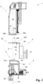
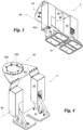
- the head 1 comprises at least one support 2 and preferably a tool holder assembly 3.
- the support 2 is the head part 1 intended to support the processing means (in detail, the tool holder assembly 3 and/or the means intended for handling the object by suitably unloading its weight on the processing machine. It is also the head part 1 in direct contact with the bridge. In detail, it is connectable to the sliding carriage on the first beam.
- the support therefore, comprises at least one frame 20.
- the frame 20 is configured to be loosely connected to the bridge.
- the frame 20 identifies the structural part of the support 2. Therefore, it is a casing or other support structure connectable to the bridge and, in detail, to said carriage. Furthermore, the support 2 may also comprise a shaft 21.
- the support 2 may comprise a cover 22 configured to define at least one housing for the shaft portion 21 proximal to the assembly 3.
- the cover 22 may be integral with the frame 20, so as to allow at least an unloading of forces between them.
- the cover 22 may comprise a plate 22a defining an access hole to the shaft 21 and, suitably, a spacer 22b of the plate 22a from the frame 20.
- the plate 22a may be annular.
- the spacer 22b may be a hollow, housing at least one portion of the shaft 21.
- the plate 22a may be integral with the frame 20, and the spacer 22b integrally binds the plate 22a to the frame 20.
- the shaft 21 may suitably define a rotation axis 2a of the shaft itself and, therefore, of the other components anchored thereto as described below.
- the axis of rotation 2a is transverse, preferably perpendicular to the direction of movement of the support 2 with respect to the bridge (in detail, to said sliding axes defined by the bridge). Therefore the axis 2a is preferably transverse, more preferably perpendicular, to the ground or to the work table on which the object is arranged (i.e. to the support surface of the base).
- the axis of rotation 2a may be vertical.
- the shaft may be configured to rotate, suitably around the axis 2a with respect to the frame 20 and the cover 22.
- the shaft 21 is a movable element with respect to the frame 20. Furthermore, it is at least in part supported by the frame 20.
- the shaft 21 may be translatable with respect to the frame 20 along the rotation axis 2a.
- the rotation of the shaft 21 may be motorized.
- the support 2 may comprise a suitably electric motor for controlling said rotation.
- the shaft 21 may identify the outlet shaft of a reducer motor.
- the tool holder assembly 3 is a device mostly known in the current state of the art. Substantially, the assembly 3 is configured to support at least one tool 30.
- the tool 30 is the element through which the tool holder assembly 3, and, therefore, the head 1, interacts with the object to process it.
- the assembly 3 allows processing of the object by means of the tool 30.
- the tool may be a tool for removing material from the object and, therefore, for cutting the object itself.
- it may comprise a cutter, a circular saw, a laser cutting device, or any other device that may allow the cutting, along at least one line, of the object.
- the tool holder assembly 3 may comprise first constraint means 31 integral with the tool holder assembly 3 to the shaft 21 which can, therefore, control the rotation of the assembly 3 around the axis 2a.
- the first constraint means 31 may comprise, or consist of, a simple hole, within which the shaft 21 can be engaged. Or, preferably, the first constraint means 31 may comprise a third flange 31a.
- the third flange 31a may be a disc-shaped or circular element, suitably protruding from the casing of the tool holder assembly 3, configured to facilitate the constraint, preferably integral, between the shaft 21 and the assembly 3.
- the shaft 21 may comprise a first flange 21a.
- the first flange 21a may identify the end of the shaft 21 that is proximal to the tool holder assembly 3.
- the first flange21a is configured to be constrained in rotation and to be precise, integral with the third flange 21a, allowing the shaft 21 to rotate the tool holder assembly 3.
- the hole in the plate 22a is configured to make the first flange 21a accessible to the third flange 31a, allowing said constraint between the flanges 21a and 31a.
- the first flange 21a is housed in the cover 22 and, in detail, in the spacer 22b.
- the head 1 may comprise gripping means 4.
- the gripping means 4 are configured to interact with the object suitably placed on said support surface, in such a way as to allow the displacement of the object and/or a part thereof suitably along said support surface.
- the means 4 are configured to firmly engage the object in order to be able to position it in a programmed point on the ground or on the work table.
- the gripping means 4 may comprise a base portion 40 and at least one gripping device 41.
- the base portion 40 is substantially the support portion on which the other elements of the gripping means 4 are constrained. Therefore, it can substantially be made from a support structure or casing.
- the gripping device 41 defines a contact surface configured to be placed in contact with object.
- the device 41 is configured to engage the object. Therefore, it can be configured to be placed into contact with object itself.
- it can comprise a suction cup or, more generally, a gasket defining said contact surface and a closed volume within which the vacuum can be created, thanks, for example, to a pump belonging to the gripping means 4.
- the gripping device 41 may be operatively connected, for example, in fluid passage connection, with a pneumatic system.
- these systems are widely known in the current state of the art and are not a particular subject of the present patent application.
- the gripping device 41 is movable with respect to the base portion 40. In particular, it is movable in such a way as to define at least two different stable positions: an operative position and a non-operative position.
- the gripping device 41 When in the operative position, preferably, the gripping device 41 may be placed in contact with the object, therefore, engaging the object, for example, by virtue of the contact of the gasket with the object following the creation of the vacuum or a depression within the volume trapped by the gasket.
- the contact surface In the operative position, the contact surface may be substantially perpendicular to the rotation axis 2a and, in detail, horizontal.
- the gripping device 41 When in the inoperative position, the gripping device 41 is substantially not in contact with the object, for example, distanced from it.
- the contact surface may be substantially parallel to the rotation axis 2a and in detail, vertical.
- the gripping device 41 is rotatable with respect to the base portion 40. In particular, it can be rotated around an operating axis 4a.
- the operating axis is preferably slanted with respect to the rotation axis 2a when the base portion 40 is constrained to the shaft 21.
- the operating axis 4a extends along a plane perpendicular to the rotation axis 2a when the base portion 40 is constrained to the shaft.
- the operating axis 4a may be parallel to the contact surface.
- the operating axis 4a may be horizontal.
- the head 1 comprises some important devices.
- the gripping means 4 comprise second constraint means 42.
- the second constraint means 42 are configured to provide a labile constraint between base portion 40 and shaft 21 and, in detail, between gripping means 4 and support 2.
- said labile constraint allows at least one relative rotation between the base portion 40 (i.e. the gripping means 4) and shaft 21 (i.e. the support 2) suitably around the rotation axis 2a.
- the entire gripping means 4 may rotate freely around and with respect to the shaft 21, and in detail to the support 2.
- said labile constraint allows said reciprocal rotation around the rotation axis 2a, and a reciprocal translation along the same axis 2a between the base 40 (i.e. the gripping means 4) and shaft 21 (i.e. the support 2). Consequently, the second means 42 are configured to constrain the gripping means 4 to the support 2, blocking their mutual translation in any direction perpendicular to the rotation axis 2a and in their reciprocal rotation around axes distinct from the rotation axis 2a.
- said labile constraint may enable a translation of the gripping means along the axis 2a also with respect to the tool holder assembly 3.
- the second constraint means 42 may be configured to define this labile constraint by unloading at least part (in some cases the totality) of the weight of the gripping means 4 on the support 2 and, in detail, on the frame 20.
- the second means 42 may comprise a simple annular element (for example a bushing or a bearing) configured to be fitted around the shaft 21, and allowing at least said free rotation between shaft 21 (in detail, the support 2) and gripping means 4.
- a simple annular element for example a bushing or a bearing
- the second constraint means 42 may comprise a second flange 42a suitably integral with the base portion 40; and at least one bearing 42b configured to be interposed between second flange 42a and shaft 21 and, in detail, between second flange 42a and support 2 (in detail the cover 22).
- the second flange 42a may be configured to rest against the support 2, in detail, on the cover 22 and in more detail on the plate 22a. It is highlighted how, as it is resting, it can translate along the axis of rotation 2a, for example, by moving away from it.
- the stroke of said translation between the support 2 and the gripping means 4 along the axis 2a may be substantially proportional to the distance along the axis 2a between the plate 22a and the frame 20, suitably subtracted from the height of the second flange 42a along the axis 2a.
- the second flange 42a may define a housing for the spacer 22b and, in detail, a housing with a larger diameter than the spacer 22b, in such a way that the constraint between the gripping means 4 and the support 2 does not interfere with the constraint between the tool holder assembly 3 and the shaft 21.
- the bearing 42b is configured to be interposed between second flange 42a and cover 22 and, in detail, between second flange 42a and spacer 22b.
- the bearing 42b is substantially an element per se known, for example, a rolling bearing, at least in part connected to the second flange 42a, and at least in part connected to the base portion 40, in such a way as to allow their reciprocal rotation around the rotation axis 2a.
- the second constraint means 42 may comprise a plurality of bearings 42b, each of which define a rolling element configured to contact the spacer 22b.
- the second constraint means 42 may comprise at least one regulator 42c of the position of the gripping means 4 with respect to the tool holder assembly 3 along the rotation axis 2a.
- the regulator 42c may be interposed between the second flange 42a and assembly 3.
- It may comprise a known adjustment screw/bolt.
- the gripping means 4 and the tool holder assembly 3 may comprise interface means 5.
- the interface means 5 are substantially interconnection elements between the gripping means 4 and the tool holder assembly 3.
- the gripping means 4 and the tool holder assembly 3 are configured to be mutually coupled, and the invention may also comprise gripping means 4 and a tool holder assembly 3 when the latter are provided with interface means 5.
- the interface means 5, in detail, are configured to block at least (preferably exclusively) the reciprocal rotation between the tool holder assembly 3 and the base portion 40. In this way, the tool holder assembly 3 may drag the gripping means 4 when rotated around the rotation axis 2a.
- the interface means 5 may be made in different ways, distinct or combined with each other.
- the interface means 5 may comprise hooks or obstruction elements configured to allow the transmission of the motion from the tool holder assembly to the gripping means 4.
- the interface means 5 may comprise at least one first wall 50 and one second wall 51.
- the first wall 50 is substantially part of the tool holder assembly 3.
- it is a wall of the casing of the tool holder assembly 3.
- the second wall 51 is preferably part of the base portion 40.
- the second wall 51 is a wall arranged on a side opposite to the side on which the gripping device 41 is positioned.
- the second wall 51 is preferably counter-shaped to the first wall 50. Therefore, the second wall 51 is configured to contact the first wall 50 when the tool holder 3 and the base portion 40 are constrained to the support 2, as described above. To ensure that the tool holder assembly and the base portion 40 do not rotate reciprocally, it is sufficient that the walls 50, 51 are flat and resting along a plane that is not perpendicular to the rotation axis 2a and, preferably, parallel to the rotation axis 2a or even slightly transverse.
- the walls 50, 51 interpenetrate, similarly to that between a male plug and a female socket, in order to be able to engage.
- the interference means 5 may alternatively or further comprise other components.
- the interference means 5 may comprise at least one limiter configured to limit (in some cases prevent) the translation of the gripping means 4 along a plane parallel to the rotation axis 2a and, in detail, along the axis 2a.
- the limiter limits and optionally prevents a translation of the gripping means 4 with respect to the support 2.
- it may be configured to limit (in some cases prevent) the reciprocal translation between the gripping means 4 and the tool holder assembly 3 when the assembly 3 and the base portion 40 are constrained to the support 2.
- the limiter may be interposed between the walls 50, 51.
- It may comprise a protruding element 52 transversely and, in detail, normally to the rotation axis 2a and a housing 53 of said protruding element 52.
- the protruding element 52 may be integral with either the tool holder 3 or the gripping means 4; with the housing 53 being integral with the other, either the tool holder 3 or the gripping means 4.
- the element 52 may be on the tool holder assembly 3 and, to be precise, on the first wall 50; the housing 53 may be integral with the gripping means 4, in detail, with the base portion 40 and in greater detail with the second wall 51.
- the protruding element 52 may be at least partially inserted in the housing 53 so as to slide freely in it for the length of the housing 53 along the rotation axis 2a.
- Said length of the housing 53 is at least equal to the stroke of the reciprocal translation between gripping means 4 and support 2 and, therefore, between means 4 and assembly 3.
- the head 1 may comprise a stop 6 sensor configured to identify a stop of the translation between support 2 and gripping means 4 along the rotation axis 2a.
- the stop 6 is configured to substantially identify a contact between frame 20 and gripping means 4 given by a reciprocal translation between support 2 and gripping means along the axis 2a. In detail, it may be configured to detect the contact between said second flange 42a and frame 20. It may comprise a pressure sensor.
- the stop 6 may be part of the support 2 and, in detail, integrated into the cover 22 and to be precise in the plate 22a or in the spacer 22b. Alternatively, it may be part of the gripping means 4 and, in detail, integrated in the second constraint means 42 and, more precisely, in the second flange 42a.
- the stop 6 may be in data connection with the control unit so as to allow said unit to control the stop of the machine when the stop 6 detects a contact between frame 20 and gripping means 4.
- the invention also comprises a method for assembling the previously described a head for a bridge processing machine.
- the method comprises at least one first constraint step wherein the base portion 40 and the shaft 21 are mutually constrained, allowing at least one reciprocal rotation thereof.
- the base portion 40 (and to be precise, the gripping means 4) are constrained to the support 2 allowing their reciprocal rotation. More in detail, in this first constraint step, the base portion 40 and, therefore, the gripping means 4 are loosely constrained to the shaft 21 and, in detail, to the support 2, allowing both their reciprocal rotation around the rotation axis 2a and their reciprocal translation 21 along the axis 2a.
- the second flange 42a is placed resting against the cover 22 and in greater detail against the plate 22a, and the at least one bearing 42b is interposed between the second flange 42a and the cover 22, and in greater detail between the second flange 42a and the spacer 42b.
- the method advantageously also includes a second constraint step wherein the tool holder assembly 3 is constrained to the said shaft 21 in such a way that the interface means 5 block at least the reciprocal rotation between the tool holder assembly 3 and the base portion 40.
- the second flange 42a rests against the cover 22 and in more detail on the plate 22a. It is, therefore, not in contact with the frame 20 and to be precise, it is spaced apart from it along the translation axis 2a. Consequently, the gripping means 4, when gripping an object, may compensate for an error (for example, a displacement or incorrect thickness of the object) by translating along the axis of rotation 2a with respect to the support 2 and the assembly 3.
- an error for example, a displacement or incorrect thickness of the object
- the head 1 for a bridge processing machine according to the invention achieves important advantages.
- the head 1 for a bridge processing machine allows reduction of the complexity of the machine, since it does not require a plurality of independent moving members for the gripping means 4 and the tool holder assembly 3, or rather, the processing means.
- the head 1 for a bridge processing machine allows the use, in the face of reduced complexity, of the gripping means 4 and the tool 3 of the tool holder assembly 3 simultaneously, since the position of the gripping device 41 is completely independent from the tool position 30.
- the head 1 allows reduction of the number of components involved in moving, when movement of the object is required with respect to the processing surface or table.
- a not secondary advantage lies in the fact that the gripping device 41, by overturning and, to be precise, arranging itself vertically when not in use vertically, allows the release by gravity of debris and dirt, which would otherwise degrade the gripping device. Moreover, this particular positioning of the gripping device 41 when not in use reduces the overall dimensions of the head 1 and, therefore, increases its maneuverability.
- shaft 21 and frame 20 may be introduced between shaft 21 and frame 20, for example, rotations around different axes with respect to the rotation axis 2a.
Landscapes
- Engineering & Computer Science (AREA)
- Mechanical Engineering (AREA)
- Mining & Mineral Resources (AREA)
- Machine Tool Units (AREA)
- Lifting Devices For Agricultural Implements (AREA)
- Manipulator (AREA)
Claims (8)
- Kopf (1) für eine Brückenbearbeitungsmaschine, umfassend:- einen Träger (2), umfassend einen Rahmen (20), der ausgebildet ist, mit einer Brücke lose verbunden zu werden, und eine Welle (21), die eine Rotationsachse (2a) definiert und in Bezug auf den Rahmen (20) zumindest um die Rotationsachse (2a) rotierbar ist,- eine Werkzeughalteranordnung (3), die ausgebildet ist, mindestens ein Werkzeug (30) zu tragen, um die Bearbeitung eines Objekts mittels des Werkzeugs (30) zu ermöglichen, und erste Beschränkungsmittel (31) umfasst, die ausgebildet sind, die Werkzeughalteranordnung (3) und die Welle (21) integral zu beschränken,- Greifmittel (4), umfassend einen Basisabschnitt (40) und mindestens eine Greifvorrichtung (41), die in Bezug auf den Basisabschnitt (40) bewegbar ist, um mindestens eine Betriebsposition zu definieren, in der diese einen Gegenstand ergreift, und eine Nichtbetriebsposition,- wobei die Greifmittel (4) zweite Beschränkungsmittel (42) umfassen, die ausgebildet sind, den Basisabschnitt (40) und die Welle (21) zu beschränken, und- wobei die Greifmittel (4) und die Werkzeughalteranordnung (3) Schnittstellenmittel (5) umfassen, die ausgebildet sind, zumindest eine reziproke Rotation zwischen der Werkzeughalteranordnung (3) und dem Basisabschnitt (40) zu blockieren, so dass die Werkzeughalteranordnung (3) das Greifmittel (4) ziehen kann, wenn diese um die Rotationsachse (2a) rotiert wird,dadurch gekennzeichnet, dass die zweiten Beschränkungsmittel (42) ausgebildet sind, eine reziproke Rotation zwischen dem Basisabschnitt (40) und der Welle (21) in Bezug auf die Rotationsachse (2a) zu ermöglichen.
- Kopf (1) nach Anspruch 1, wobei die zweiten Beschränkungsmittel (42) ausgebildet sind, zumindest einen Teil des Gewichts der Greifmittel auf den Rahmen (20) zu entladen.
- Kopf (1) nach einem der vorhergehenden Ansprüche, wobei die Welle (21) an einem freien Ende einen ersten Flansch (21a) umfasst; wobei die Werkzeughalteranordnung (3) einen dritten Flansch (31a) umfasst, der ausgebildet ist, in Rotation gegenüber dem ersten Flansch (21a) beschränkt zu werden; wobei der Träger (2) eine Platte (22a), die ein Zugangsloch zu der Welle (21) definiert, und einen Abstandshalter (22b) der Platte (22a) von dem Rahmen (20) umfasst; wobei das Loch der Platte (22a) ausgebildet ist, den ersten Flansch (21a) für den dritten Flansch (31a) zugänglich zu machen; und wobei die zweiten Beschränkungsmittel (42) einen zweiten Flansch (42a), der ausgebildet ist, auf der Platte (22a) zu ruhen, und ein zwischen dem zweiten Flansch (42a) und dem Abstandshalter (22b) angeordnetes Lager (42b) umfassen.
- Kopf (1) nach Anspruch 3, umfassend einen Anschlag (6), der ausgebildet ist, den Kontakt zwischen dem zweiten Flansch (42a) und dem Rahmen (20) zu erfassen.
- Kopf (1) nach einem der Ansprüche 1-4, wobei die Schnittstellenmittel (5) mindestens ein erstes Wandteil (50) der Werkzeughalteranordnung (3) und ein zweites Wandteil (51) des Basisabschnitts (40) umfassen, das zur ersten Wand (50) eine Gegenform aufweist und ausgebildet ist, mit der ersten Wand (50) in Kontakt zu kommen, wenn die Werkzeughalteranordnung (3) und der Basisabschnitt (40) an der Welle (21) beschränkt sind.
- Kopf (1) nach einem der Ansprüche 1-5, wobei die Schnittstellenmittel (5) mindestens einen Begrenzer (52, 53) der reziproken Bewegung zwischen der Werkzeughalteranordnung (3) und den Greifmitteln (4) entlang der Rotationsachse (2a) umfassen, wenn die Werkzeughalteranordnung (3) und der Basisabschnitt (40) an der Welle (21) beschränkt sind.
- Kopf (1) nach einem der Ansprüche 1-6, wobei die Greifvorrichtung (41) in Bezug auf den Basisabschnitt (40) um eine Betriebsachse (4a) rotierbar ist, die in Bezug auf die Rotationsachse (2a) geneigt ist und sich entlang einer Ebene senkrecht zu der Rotationsachse erstreckt, wenn der Basisabschnitt (40) an der Welle (21) beschränkt ist.
- Verfahren zum Zusammenbau eines Kopfes (1) für eine Brückenbearbeitungsmaschine nach einem der Ansprüche 1-7, dadurch gekennzeichnet, dass es umfasst:- Beschränken des Basisabschnitts (40) und der Welle (21), um eine reziproke Rotation zwischen dem Basisabschnitt (40) und der Welle (21) in Bezug auf die Rotationsachse (2a) zu ermöglichen, und- Beschränken der Werkzeughalteranordnung (3) an der Welle (21) derart, dass die Schnittstellenmittel (5) zumindest die reziproke Rotation zwischen der Werkzeughalteranordnung (3) und dem Basisabschnitt (40) blockieren.
Applications Claiming Priority (1)
| Application Number | Priority Date | Filing Date | Title |
|---|---|---|---|
| IT102021000023786A IT202100023786A1 (it) | 2021-09-15 | 2021-09-15 | Testa per macchina da lavorazione a ponte |
Publications (2)
| Publication Number | Publication Date |
|---|---|
| EP4151379A1 EP4151379A1 (de) | 2023-03-22 |
| EP4151379B1 true EP4151379B1 (de) | 2024-06-19 |
Family
ID=78771011
Family Applications (1)
| Application Number | Title | Priority Date | Filing Date |
|---|---|---|---|
| EP22195038.9A Active EP4151379B1 (de) | 2021-09-15 | 2022-09-12 | Kopf für eine brückenbearbeitungsmaschine |
Country Status (3)
| Country | Link |
|---|---|
| US (1) | US12208540B2 (de) |
| EP (1) | EP4151379B1 (de) |
| IT (1) | IT202100023786A1 (de) |
Family Cites Families (10)
| Publication number | Priority date | Publication date | Assignee | Title |
|---|---|---|---|---|
| DE102009022784A1 (de) * | 2009-05-19 | 2010-11-25 | Burkhardt Gmbh | Plattenbearbeitungsmaschine von Platten aus Stein, Holz, Metall und/oder deren Ersatzwerkstoffen |
| IT1399931B1 (it) | 2010-05-17 | 2013-05-09 | Gmm S P A | Macchina per la lavorazione di materiali in blocco o in lastra e metodo di lavorazione attuabile tramite tale macchina |
| ITMI20150580A1 (it) * | 2015-04-22 | 2016-10-22 | Gmm S P A | Macchina per la lavorazione di materiali in lastra |
| ES2882668T3 (es) * | 2018-09-10 | 2021-12-02 | Sassomeccanica S P A | Máquina con herramientas intercambiables para el procesamiento de materiales laminados |
| IT201800020725A1 (it) * | 2018-12-21 | 2020-06-21 | Simec Spa | Dispositivo di manipolazione e taglio e macchina utensile con tale dispositivo di manipolazione e taglio |
| IT201900010041A1 (it) * | 2019-06-25 | 2020-12-25 | Breton Spa | Banco per il supporto e la movimentazione di manufatti e macchina per la lavorazione ed il taglio di manufatti |
| IT201900014460A1 (it) * | 2019-08-08 | 2021-02-08 | Helios Automazioni S R L | Macchina per il taglio di lastre, particolarmente in marmo, granito, vetro e materiali compositi |
| IT202000010936A1 (it) * | 2020-05-13 | 2021-11-13 | Cms Spa | Centro di lavoro per tagliare oggetti |
| IT202100000497A1 (it) * | 2021-01-13 | 2022-07-13 | Gmm S P A | Apparato e metodo per movimentare coppie di pezzi lavorati aventi una faccia grezza e una opposta faccia rifinita |
| CA3126111A1 (en) * | 2021-07-27 | 2023-01-27 | 2721111 Ontario Inc. | Stone slab transfer and processing system and methods |
-
2021
- 2021-09-15 IT IT102021000023786A patent/IT202100023786A1/it unknown
-
2022
- 2022-09-12 EP EP22195038.9A patent/EP4151379B1/de active Active
- 2022-09-14 US US17/944,585 patent/US12208540B2/en active Active
Also Published As
| Publication number | Publication date |
|---|---|
| EP4151379A1 (de) | 2023-03-22 |
| IT202100023786A1 (it) | 2023-03-15 |
| US12208540B2 (en) | 2025-01-28 |
| US20230078367A1 (en) | 2023-03-16 |
Similar Documents
| Publication | Publication Date | Title |
|---|---|---|
| RU2549799C2 (ru) | Станок для обработки материалов в блоках или плитах и способ обработки на этом станке | |
| US11186399B2 (en) | Automated container cutting apparatus | |
| US5558560A (en) | Tool grinding machine | |
| KR20170107406A (ko) | 유지보수 장치 | |
| EP4151379A1 (de) | Kopf für eine brückenbearbeitungsmaschine | |
| KR101873173B1 (ko) | 복합 밀링 장치 | |
| CA2975478C (en) | BEVELING HEAD FOR MULTIAXIAL METAL PROCESSING | |
| AU2018239825B2 (en) | Cutting machine part transfer apparatus | |
| EP0957417B1 (de) | Werkstückformmessungsverfahren und -vorrichtung, und Koördinatenmessmaschine | |
| EP4257317B1 (de) | Numerisch gesteuertes bearbeitungszentrum für glasscheiben oder natursteinplatten mit bearbeitungskopf mit hilfsplattenträger und bearbeitungsverfahren | |
| US6608282B2 (en) | Machine tool loading apparatus | |
| KR102557449B1 (ko) | 3차원 스캐닝을 이용한 자동화된 절삭 가공 시스템 | |
| KR102620717B1 (ko) | 자동 어태치먼트 교환장치 및 이의 제어방법 | |
| CN112536871A (zh) | 扫码型数控锯切系统及其加工方法 | |
| KR101079281B1 (ko) | 작업부의 확인이 가능한 중,대형 가공기 | |
| KR101045553B1 (ko) | 목형 가공기 | |
| JP2001121301A (ja) | 主軸移動型立形工作機械 | |
| KR20120069194A (ko) | 선반 방진구 쉘 교체장치 | |
| CN113858377A (zh) | 一种封边机刮边机构 | |
| CN119839689B (zh) | 一种方形法兰柔性加工生产线及控制方法 | |
| JPH0357332Y2 (de) | ||
| CN109909785B (zh) | 托起组件、托起系统、盘类工件翻转系统及翻转方法 | |
| EP4434708A1 (de) | Bearbeitungszentrum zur bearbeitung von steinplatten | |
| JPH09136236A (ja) | 工作機械のパレット交換装置 | |
| EP4257319A1 (de) | Numerisch gesteuertes bearbeitungszentrum zur bearbeitung von platten aus glas oder platten aus natur- oder kunststeinmaterial und entsprechendes bearbeitungsverfahren |
Legal Events
| Date | Code | Title | Description |
|---|---|---|---|
| PUAI | Public reference made under article 153(3) epc to a published international application that has entered the european phase |
Free format text: ORIGINAL CODE: 0009012 |
|
| STAA | Information on the status of an ep patent application or granted ep patent |
Free format text: STATUS: THE APPLICATION HAS BEEN PUBLISHED |
|
| AK | Designated contracting states |
Kind code of ref document: A1 Designated state(s): AL AT BE BG CH CY CZ DE DK EE ES FI FR GB GR HR HU IE IS IT LI LT LU LV MC MK MT NL NO PL PT RO RS SE SI SK SM TR |
|
| STAA | Information on the status of an ep patent application or granted ep patent |
Free format text: STATUS: REQUEST FOR EXAMINATION WAS MADE |
|
| 17P | Request for examination filed |
Effective date: 20230503 |
|
| RBV | Designated contracting states (corrected) |
Designated state(s): AL AT BE BG CH CY CZ DE DK EE ES FI FR GB GR HR HU IE IS IT LI LT LU LV MC MK MT NL NO PL PT RO RS SE SI SK SM TR |
|
| GRAP | Despatch of communication of intention to grant a patent |
Free format text: ORIGINAL CODE: EPIDOSNIGR1 |
|
| STAA | Information on the status of an ep patent application or granted ep patent |
Free format text: STATUS: GRANT OF PATENT IS INTENDED |
|
| INTG | Intention to grant announced |
Effective date: 20240206 |
|
| GRAS | Grant fee paid |
Free format text: ORIGINAL CODE: EPIDOSNIGR3 |
|
| GRAA | (expected) grant |
Free format text: ORIGINAL CODE: 0009210 |
|
| STAA | Information on the status of an ep patent application or granted ep patent |
Free format text: STATUS: THE PATENT HAS BEEN GRANTED |
|
| AK | Designated contracting states |
Kind code of ref document: B1 Designated state(s): AL AT BE BG CH CY CZ DE DK EE ES FI FR GB GR HR HU IE IS IT LI LT LU LV MC MK MT NL NO PL PT RO RS SE SI SK SM TR |
|
| REG | Reference to a national code |
Ref country code: GB Ref legal event code: FG4D |
|
| REG | Reference to a national code |
Ref country code: CH Ref legal event code: EP |
|
| REG | Reference to a national code |
Ref country code: DE Ref legal event code: R096 Ref document number: 602022004018 Country of ref document: DE |
|
| PG25 | Lapsed in a contracting state [announced via postgrant information from national office to epo] |
Ref country code: BG Free format text: LAPSE BECAUSE OF FAILURE TO SUBMIT A TRANSLATION OF THE DESCRIPTION OR TO PAY THE FEE WITHIN THE PRESCRIBED TIME-LIMIT Effective date: 20240619 |
|
| PG25 | Lapsed in a contracting state [announced via postgrant information from national office to epo] |
Ref country code: FI Free format text: LAPSE BECAUSE OF FAILURE TO SUBMIT A TRANSLATION OF THE DESCRIPTION OR TO PAY THE FEE WITHIN THE PRESCRIBED TIME-LIMIT Effective date: 20240619 Ref country code: HR Free format text: LAPSE BECAUSE OF FAILURE TO SUBMIT A TRANSLATION OF THE DESCRIPTION OR TO PAY THE FEE WITHIN THE PRESCRIBED TIME-LIMIT Effective date: 20240619 |
|
| REG | Reference to a national code |
Ref country code: LT Ref legal event code: MG9D |
|
| PG25 | Lapsed in a contracting state [announced via postgrant information from national office to epo] |
Ref country code: GR Free format text: LAPSE BECAUSE OF FAILURE TO SUBMIT A TRANSLATION OF THE DESCRIPTION OR TO PAY THE FEE WITHIN THE PRESCRIBED TIME-LIMIT Effective date: 20240920 |
|
| REG | Reference to a national code |
Ref country code: NL Ref legal event code: MP Effective date: 20240619 |
|
| PG25 | Lapsed in a contracting state [announced via postgrant information from national office to epo] |
Ref country code: LV Free format text: LAPSE BECAUSE OF FAILURE TO SUBMIT A TRANSLATION OF THE DESCRIPTION OR TO PAY THE FEE WITHIN THE PRESCRIBED TIME-LIMIT Effective date: 20240619 |
|
| PG25 | Lapsed in a contracting state [announced via postgrant information from national office to epo] |
Ref country code: NO Free format text: LAPSE BECAUSE OF FAILURE TO SUBMIT A TRANSLATION OF THE DESCRIPTION OR TO PAY THE FEE WITHIN THE PRESCRIBED TIME-LIMIT Effective date: 20240919 Ref country code: LV Free format text: LAPSE BECAUSE OF FAILURE TO SUBMIT A TRANSLATION OF THE DESCRIPTION OR TO PAY THE FEE WITHIN THE PRESCRIBED TIME-LIMIT Effective date: 20240619 Ref country code: HR Free format text: LAPSE BECAUSE OF FAILURE TO SUBMIT A TRANSLATION OF THE DESCRIPTION OR TO PAY THE FEE WITHIN THE PRESCRIBED TIME-LIMIT Effective date: 20240619 Ref country code: GR Free format text: LAPSE BECAUSE OF FAILURE TO SUBMIT A TRANSLATION OF THE DESCRIPTION OR TO PAY THE FEE WITHIN THE PRESCRIBED TIME-LIMIT Effective date: 20240920 Ref country code: FI Free format text: LAPSE BECAUSE OF FAILURE TO SUBMIT A TRANSLATION OF THE DESCRIPTION OR TO PAY THE FEE WITHIN THE PRESCRIBED TIME-LIMIT Effective date: 20240619 Ref country code: BG Free format text: LAPSE BECAUSE OF FAILURE TO SUBMIT A TRANSLATION OF THE DESCRIPTION OR TO PAY THE FEE WITHIN THE PRESCRIBED TIME-LIMIT Effective date: 20240619 Ref country code: RS Free format text: LAPSE BECAUSE OF FAILURE TO SUBMIT A TRANSLATION OF THE DESCRIPTION OR TO PAY THE FEE WITHIN THE PRESCRIBED TIME-LIMIT Effective date: 20240919 |
|
| PG25 | Lapsed in a contracting state [announced via postgrant information from national office to epo] |
Ref country code: NL Free format text: LAPSE BECAUSE OF FAILURE TO SUBMIT A TRANSLATION OF THE DESCRIPTION OR TO PAY THE FEE WITHIN THE PRESCRIBED TIME-LIMIT Effective date: 20240619 |
|
| REG | Reference to a national code |
Ref country code: AT Ref legal event code: UEP Ref document number: 1695664 Country of ref document: AT Kind code of ref document: T Effective date: 20240619 |
|
| PG25 | Lapsed in a contracting state [announced via postgrant information from national office to epo] |
Ref country code: NL Free format text: LAPSE BECAUSE OF FAILURE TO SUBMIT A TRANSLATION OF THE DESCRIPTION OR TO PAY THE FEE WITHIN THE PRESCRIBED TIME-LIMIT Effective date: 20240619 |
|
| PG25 | Lapsed in a contracting state [announced via postgrant information from national office to epo] |
Ref country code: PT Free format text: LAPSE BECAUSE OF FAILURE TO SUBMIT A TRANSLATION OF THE DESCRIPTION OR TO PAY THE FEE WITHIN THE PRESCRIBED TIME-LIMIT Effective date: 20241021 |
|
| PG25 | Lapsed in a contracting state [announced via postgrant information from national office to epo] |
Ref country code: PT Free format text: LAPSE BECAUSE OF FAILURE TO SUBMIT A TRANSLATION OF THE DESCRIPTION OR TO PAY THE FEE WITHIN THE PRESCRIBED TIME-LIMIT Effective date: 20241021 |
|
| PG25 | Lapsed in a contracting state [announced via postgrant information from national office to epo] |
Ref country code: PL Free format text: LAPSE BECAUSE OF FAILURE TO SUBMIT A TRANSLATION OF THE DESCRIPTION OR TO PAY THE FEE WITHIN THE PRESCRIBED TIME-LIMIT Effective date: 20240619 |
|
| PG25 | Lapsed in a contracting state [announced via postgrant information from national office to epo] |
Ref country code: EE Free format text: LAPSE BECAUSE OF FAILURE TO SUBMIT A TRANSLATION OF THE DESCRIPTION OR TO PAY THE FEE WITHIN THE PRESCRIBED TIME-LIMIT Effective date: 20240619 |
|
| PG25 | Lapsed in a contracting state [announced via postgrant information from national office to epo] |
Ref country code: IS Free format text: LAPSE BECAUSE OF FAILURE TO SUBMIT A TRANSLATION OF THE DESCRIPTION OR TO PAY THE FEE WITHIN THE PRESCRIBED TIME-LIMIT Effective date: 20241019 |
|
| PG25 | Lapsed in a contracting state [announced via postgrant information from national office to epo] |
Ref country code: CZ Free format text: LAPSE BECAUSE OF FAILURE TO SUBMIT A TRANSLATION OF THE DESCRIPTION OR TO PAY THE FEE WITHIN THE PRESCRIBED TIME-LIMIT Effective date: 20240619 |
|
| PG25 | Lapsed in a contracting state [announced via postgrant information from national office to epo] |
Ref country code: RO Free format text: LAPSE BECAUSE OF FAILURE TO SUBMIT A TRANSLATION OF THE DESCRIPTION OR TO PAY THE FEE WITHIN THE PRESCRIBED TIME-LIMIT Effective date: 20240619 Ref country code: SK Free format text: LAPSE BECAUSE OF FAILURE TO SUBMIT A TRANSLATION OF THE DESCRIPTION OR TO PAY THE FEE WITHIN THE PRESCRIBED TIME-LIMIT Effective date: 20240619 |
|
| PG25 | Lapsed in a contracting state [announced via postgrant information from national office to epo] |
Ref country code: SM Free format text: LAPSE BECAUSE OF FAILURE TO SUBMIT A TRANSLATION OF THE DESCRIPTION OR TO PAY THE FEE WITHIN THE PRESCRIBED TIME-LIMIT Effective date: 20240619 Ref country code: ES Free format text: LAPSE BECAUSE OF FAILURE TO SUBMIT A TRANSLATION OF THE DESCRIPTION OR TO PAY THE FEE WITHIN THE PRESCRIBED TIME-LIMIT Effective date: 20240619 |
|
| PG25 | Lapsed in a contracting state [announced via postgrant information from national office to epo] |
Ref country code: SM Free format text: LAPSE BECAUSE OF FAILURE TO SUBMIT A TRANSLATION OF THE DESCRIPTION OR TO PAY THE FEE WITHIN THE PRESCRIBED TIME-LIMIT Effective date: 20240619 Ref country code: SK Free format text: LAPSE BECAUSE OF FAILURE TO SUBMIT A TRANSLATION OF THE DESCRIPTION OR TO PAY THE FEE WITHIN THE PRESCRIBED TIME-LIMIT Effective date: 20240619 Ref country code: RO Free format text: LAPSE BECAUSE OF FAILURE TO SUBMIT A TRANSLATION OF THE DESCRIPTION OR TO PAY THE FEE WITHIN THE PRESCRIBED TIME-LIMIT Effective date: 20240619 Ref country code: PL Free format text: LAPSE BECAUSE OF FAILURE TO SUBMIT A TRANSLATION OF THE DESCRIPTION OR TO PAY THE FEE WITHIN THE PRESCRIBED TIME-LIMIT Effective date: 20240619 Ref country code: IS Free format text: LAPSE BECAUSE OF FAILURE TO SUBMIT A TRANSLATION OF THE DESCRIPTION OR TO PAY THE FEE WITHIN THE PRESCRIBED TIME-LIMIT Effective date: 20241019 Ref country code: ES Free format text: LAPSE BECAUSE OF FAILURE TO SUBMIT A TRANSLATION OF THE DESCRIPTION OR TO PAY THE FEE WITHIN THE PRESCRIBED TIME-LIMIT Effective date: 20240619 Ref country code: EE Free format text: LAPSE BECAUSE OF FAILURE TO SUBMIT A TRANSLATION OF THE DESCRIPTION OR TO PAY THE FEE WITHIN THE PRESCRIBED TIME-LIMIT Effective date: 20240619 Ref country code: CZ Free format text: LAPSE BECAUSE OF FAILURE TO SUBMIT A TRANSLATION OF THE DESCRIPTION OR TO PAY THE FEE WITHIN THE PRESCRIBED TIME-LIMIT Effective date: 20240619 |
|
| REG | Reference to a national code |
Ref country code: DE Ref legal event code: R097 Ref document number: 602022004018 Country of ref document: DE |
|
| PG25 | Lapsed in a contracting state [announced via postgrant information from national office to epo] |
Ref country code: DK Free format text: LAPSE BECAUSE OF FAILURE TO SUBMIT A TRANSLATION OF THE DESCRIPTION OR TO PAY THE FEE WITHIN THE PRESCRIBED TIME-LIMIT Effective date: 20240619 |
|
| PG25 | Lapsed in a contracting state [announced via postgrant information from national office to epo] |
Ref country code: MC Free format text: LAPSE BECAUSE OF FAILURE TO SUBMIT A TRANSLATION OF THE DESCRIPTION OR TO PAY THE FEE WITHIN THE PRESCRIBED TIME-LIMIT Effective date: 20240619 |
|
| PLBE | No opposition filed within time limit |
Free format text: ORIGINAL CODE: 0009261 |
|
| STAA | Information on the status of an ep patent application or granted ep patent |
Free format text: STATUS: NO OPPOSITION FILED WITHIN TIME LIMIT |
|
| PG25 | Lapsed in a contracting state [announced via postgrant information from national office to epo] |
Ref country code: LU Free format text: LAPSE BECAUSE OF NON-PAYMENT OF DUE FEES Effective date: 20240912 |
|
| 26N | No opposition filed |
Effective date: 20250320 |
|
| REG | Reference to a national code |
Ref country code: BE Ref legal event code: MM Effective date: 20240930 |
|
| PG25 | Lapsed in a contracting state [announced via postgrant information from national office to epo] |
Ref country code: BE Free format text: LAPSE BECAUSE OF NON-PAYMENT OF DUE FEES Effective date: 20240930 |
|
| PG25 | Lapsed in a contracting state [announced via postgrant information from national office to epo] |
Ref country code: FR Free format text: LAPSE BECAUSE OF NON-PAYMENT OF DUE FEES Effective date: 20240930 |
|
| PG25 | Lapsed in a contracting state [announced via postgrant information from national office to epo] |
Ref country code: IE Free format text: LAPSE BECAUSE OF NON-PAYMENT OF DUE FEES Effective date: 20240912 |
|
| PG25 | Lapsed in a contracting state [announced via postgrant information from national office to epo] |
Ref country code: SE Free format text: LAPSE BECAUSE OF FAILURE TO SUBMIT A TRANSLATION OF THE DESCRIPTION OR TO PAY THE FEE WITHIN THE PRESCRIBED TIME-LIMIT Effective date: 20240619 |
|
| PGFP | Annual fee paid to national office [announced via postgrant information from national office to epo] |
Ref country code: DE Payment date: 20250926 Year of fee payment: 4 |
|
| PGFP | Annual fee paid to national office [announced via postgrant information from national office to epo] |
Ref country code: AT Payment date: 20251020 Year of fee payment: 4 |
|
| PGFP | Annual fee paid to national office [announced via postgrant information from national office to epo] |
Ref country code: IT Payment date: 20250930 Year of fee payment: 4 |
|
| PG25 | Lapsed in a contracting state [announced via postgrant information from national office to epo] |
Ref country code: CY Free format text: LAPSE BECAUSE OF FAILURE TO SUBMIT A TRANSLATION OF THE DESCRIPTION OR TO PAY THE FEE WITHIN THE PRESCRIBED TIME-LIMIT; INVALID AB INITIO Effective date: 20220912 |
|
| PG25 | Lapsed in a contracting state [announced via postgrant information from national office to epo] |
Ref country code: HU Free format text: LAPSE BECAUSE OF FAILURE TO SUBMIT A TRANSLATION OF THE DESCRIPTION OR TO PAY THE FEE WITHIN THE PRESCRIBED TIME-LIMIT; INVALID AB INITIO Effective date: 20220912 |
|
| REG | Reference to a national code |
Ref country code: CH Ref legal event code: H13 Free format text: ST27 STATUS EVENT CODE: U-0-0-H10-H13 (AS PROVIDED BY THE NATIONAL OFFICE) Effective date: 20260504 |