EP0957417B1 - Werkstückformmessungsverfahren und -vorrichtung, und Koördinatenmessmaschine - Google Patents
Werkstückformmessungsverfahren und -vorrichtung, und Koördinatenmessmaschine Download PDFInfo
- Publication number
- EP0957417B1 EP0957417B1 EP99303581A EP99303581A EP0957417B1 EP 0957417 B1 EP0957417 B1 EP 0957417B1 EP 99303581 A EP99303581 A EP 99303581A EP 99303581 A EP99303581 A EP 99303581A EP 0957417 B1 EP0957417 B1 EP 0957417B1
- Authority
- EP
- European Patent Office
- Prior art keywords
- workpiece
- coordinate
- measuring
- machining
- measuring machine
- Prior art date
- Legal status (The legal status is an assumption and is not a legal conclusion. Google has not performed a legal analysis and makes no representation as to the accuracy of the status listed.)
- Expired - Lifetime
Links
Images




Classifications
-
- G—PHYSICS
- G05—CONTROLLING; REGULATING
- G05B—CONTROL OR REGULATING SYSTEMS IN GENERAL; FUNCTIONAL ELEMENTS OF SUCH SYSTEMS; MONITORING OR TESTING ARRANGEMENTS FOR SUCH SYSTEMS OR ELEMENTS
- G05B19/00—Program-control systems
- G05B19/02—Program-control systems electric
- G05B19/18—Numerical control [NC], i.e. automatically operating machines, in particular machine tools, e.g. in a manufacturing environment, so as to execute positioning, movement or co-ordinated operations by means of program data in numerical form
- G05B19/401—Numerical control [NC], i.e. automatically operating machines, in particular machine tools, e.g. in a manufacturing environment, so as to execute positioning, movement or co-ordinated operations by means of program data in numerical form characterised by control arrangements for measuring, e.g. calibration and initialisation, measuring workpiece for machining purposes
-
- Y—GENERAL TAGGING OF NEW TECHNOLOGICAL DEVELOPMENTS; GENERAL TAGGING OF CROSS-SECTIONAL TECHNOLOGIES SPANNING OVER SEVERAL SECTIONS OF THE IPC; TECHNICAL SUBJECTS COVERED BY FORMER USPC CROSS-REFERENCE ART COLLECTIONS [XRACs] AND DIGESTS
- Y10—TECHNICAL SUBJECTS COVERED BY FORMER USPC
- Y10T—TECHNICAL SUBJECTS COVERED BY FORMER US CLASSIFICATION
- Y10T29/00—Metal working
- Y10T29/51—Plural diverse manufacturing apparatus including means for metal shaping or assembling
- Y10T29/5196—Multiple station with conveyor
-
- Y—GENERAL TAGGING OF NEW TECHNOLOGICAL DEVELOPMENTS; GENERAL TAGGING OF CROSS-SECTIONAL TECHNOLOGIES SPANNING OVER SEVERAL SECTIONS OF THE IPC; TECHNICAL SUBJECTS COVERED BY FORMER USPC CROSS-REFERENCE ART COLLECTIONS [XRACs] AND DIGESTS
- Y10—TECHNICAL SUBJECTS COVERED BY FORMER USPC
- Y10T—TECHNICAL SUBJECTS COVERED BY FORMER US CLASSIFICATION
- Y10T409/00—Gear cutting, milling, or planing
- Y10T409/30—Milling
- Y10T409/303864—Milling with means to weigh or test work or product
Definitions
- the present invention relates to a work form-measuring method and device, and a coordinate-measuring machine, in particular to a work form-measuring method and device, and a coordinate-measuring machine which are capable of measuring the forms and dimensions of a work machined by a machine tool such as a machining center, immediately after the machining, by a coordinate-measuring machine such as a three-dimensional coordinate measuring machine, to shorten the production line tact including the measurement, and then to carry out the feedback of the measured data promptly.
- a coordinate-measuring machine in particular to a work form-measuring method and device, and a coordinate-measuring machine which are capable of measuring the forms and dimensions of a work machined by a machine tool such as a machining center, immediately after the machining, by a coordinate-measuring machine such as a three-dimensional coordinate measuring machine, to shorten the production line tact including the measurement, and then to carry out the feedback of the measured data promptly.
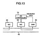
- a machining line comprises a plurality of machining centers (hereinafter also referred to as "the M/C") 20, and a conveying loader 40 to which the machining centers 20 are connected, and further includes three-dimensional coordinate-measuring machines (hereinafter also referred to as "the CMM") 50.
- the three-dimensional coordinate-measuring machine 50 is arranged in the same row as the machining center 20 as one station of the machining line.
- the work machined by one of the machining centers 20 is subjected to the measurement carried out by the three-dimensional coordinate-measuring machine 50 at the next step, according to the following processes:
- the conveying process ii) by the conveying loader 40 includes, in detail, the process of taking out, conveying, and taking in the work, which requires a lot of time. This results in an obstacle to shorten the whole line tact, in spite of the acceleration of each of the machining process i) and the measuring process iii).
- US4473883 describes such known apparatus in which a conveying system transfers pallets between stations for respective workpiece machining and measuring operations.
- DE3417741A1 also describes a measuring device and GB2108715A describes a machining centre.
- the present invention has been made in order to solve the above conventional problems. It is therefore an object of the present invention to provide a work form-measuring method and device which are capable of shortening the production line tact including the measurement, and then promptly carrying out the feedback of the measured data from a coordinate-measuring machine to a machining tool.
- the present invention provides a workpiece-measuring method comprising the steps of :
- the direction of the probe of the coordinate-measuring machine moving to the work is the same as that of a tool of the machining tool moving to the work, thereby enabling the work to be subjected to the measurement in the same condition (posture, supporting method, clamping method and on) as the machining tool, which provides a highly accurate measurement.
- the direction of the tool of the machining tool moving to the work and that of the probe of the coordinate-measuring machine moving to the work both are horizontal, which facilitates the arrangement of the machining tool and the coordinate-measuring machine.
- the coordinate-measuring machine is capable of taking refuge to such a position as that the coordinate-measuring machine does not prevent the work from moving, which provides a highly accurate measurement without excessively increasing the respective lengths of the spindle and the probe of the coordinate-measuring machine, and without increasing the coordinate-measuring machine in size.
- the present invention also provides a workpiece-measuring apparatus comprising:
- the work-measuring apparatus further comprises refuge means for causing the coordinate-measuring machine to take refuge to such a position as that the coordinate-measuring machine does not prevent the work from moving.
- the refuge means is adapted to cause the coordinate-measuring machine to take refuge in a linear motion manner, which requires only simple construction to take refuge.
- the refuge means is adapted to cause the coordinate-measuring machine to take refuge in a rotational motion manner, which requires only small occupation space to take refuge.
- the present invention provides a coordinate-measuring machine disposed in the vicinity of a machining tool for getting a probe thereof close to a work, having machined by the machining tool, placed on a waiting position, to thereby measure the forms and dimensions of the work, which causes the coordinate-measuring machine to be easily installed into machining line.
- the machining tool and the coordinate-measuring machine are adapted to mutually exchange a measurement enabling signal and a measurement completion signal, both of which are related to the movement of the work by the changer, which causes the machining tool and the coordinate-measuring machine to be surely operated.
- the coordinate-measuring machine leaves a refuge position after having received a signal of informing a change movement completion, from the machining tool, and the changer starts moving the work after having received a signal of informing a coordinate-measuring machine refuge completion.
- the work form-measuring apparatus preferably further comprises rotating means for rotating the work which is placed on a measuring position, which causes the work to be measured in all or multi-side faces.
- the forms and dimensions of the work, having been machined by the machining tool can be immediately after the machining, thereby resulting in the shortage of the production line tact including the measurement, and the acceleration of the feed back of the measured data from the coordinate-measuring machine to the machining tool.
- the coordinate-measuring machine which is conventionally required to be used at a sampling inspection process or a final process, can be used at an intermediate process between the machining tools, which enables the measurement in the line to be ideally carried out, and then the machining and the measurement can be carried out in parallel, thereby enabling a true error of the machining tool to be extracted, which enables an optimum feedback value to be obtained.
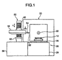
- FIG. 1 A first embodiment of the invention will be described hereinbelow with reference to Fig. 1 of a front view, Fig. 2 of a plan view, and Fig. 3 of a perspective view.
- a machining center such as a horizontal type machining center (M/C) 20 shown in Fig. 4 for example, is disposed a horizontal type three-dimensional coordinate-measuring machine (CMM) 50.
- the machining center 20 has a horizontal main spindle 22, and the three-dimensional coordinate-measuring machine 50 has a horizontally movable spindle 54 to which a probe 52 is attached.
- a work 10 (See Fig. 4) is moved to a waiting position after it has been machined by the machining center 20, where the form of the work 10 is measured by the probe 52 of the CMM getting close to the work 10.
- reference numeral 21 designates a base of the M/C 20, 22 a main spindle to which is attached a cutting tool, such as a drill, a face mill, and a tap, for machining the work 10 moving in a Z-axis direction Zm of the M/C 20, 23 a machining index (rotation) mechanism for rotating the work 10 by a predetermined angle at the machining position, 26 a two-position rotational type auto pallet changer (hereinafter also referred to as "the APC"), and 29 a base of the APC 26.
- the APC 26 includes a plate 28 for rotating the work 10, which is taken in from and out to a conveying loader (not shown) and placed on a pallet 12, as shown by the arrow R in Fig. 5, to move the work 10 between the waiting position of a lower side in Fig. 2, and a machining position of an upper side in Fig. 2.
- a partition plate 30 is, on occasion demands, uprightly disposed between the machining position and the waiting position, for preventing chips and oil occurring during the machining from being splashed.
- Reference numeral 54 designates a spindle of the CMM 50, 56 a base of the CMM 50, 58 a Z-axis cover covering a Z-axis direction moving mechanism for moving the spindle 54 in a horizontal Z-axis direction, 60 a Y-axis cover for covering a Y-axis direction moving mechanism for moving the Z-axis direction moving mechanism 58 in a vertical Y-axis direction, and 62 an X-axis cover for covering an X-axis direction moving mechanism for moving the Y-axis direction moving mechanism 60 in a horizontal X-axis direction perpendicular to drawing sheet of Fig. 1 (See Fig. 2).
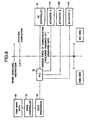
- Fig. 6 a system of the first embodiment in which various kinds of communication including the feedback of the measured data are carried out between a NC controller 70 on a side of the M/C 20 and a programmable controller (hereinafter also referred to as "the PLC") 72 on a side of the CMM 50.
- the instruction of the PLC 72 causes a drive controller 78 and a data processor 76 to transmit the data mutually, in which the drive controller 78 controls actuators 74A, 74B, 74C such as jig clamps, and a main body of the CMM 50.
- the CMM 50 performs the measurement.
- the work 10 is rotated (turns in its axis) by an optional angle, e.g. 90° by the measuring index mechanism 24, and then the next side face of the work 10 is measured. In this manner, repeating the 90°, for example, -rotation and the measurement causes all the side faces of the work 10 to be measured.
- the CMM 50 transmits a work (or pallet)-conveying instruction to the NC controller 70, and the work, having been measured, is taken out to the conveying loader 40, and then the next work 10 is taken in from the conveying loader 40 to the waiting position.
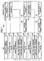
- a step 100 the work 10 to be next machined, as shown in Fig. 8, on the M/C 20 is taken in to a portion A of plate 28 of the APC 26 which is located on a side of the conveying loader 40 at this point of time.
- the plate 28 of the APC 26 is rotated by 180° as shown by the arrow R at a step 120, and the work 10 placed on the portion A, which is turned to be located on the machining position (i.e., on a side of the M/C 20), is machined by the M/C 20 at a step 130.
- the next work 10 is taken in from the conveying loader 40 to a portion B, which is located on the waiting position (i.e., on a side of the conveying loader 40), during the machining at a step 132.
- a step 140 waiting condition continues until both the machining completion and the next work taking-in completion are confirmed. Then, when the confirmation is made, the plate 28 of the APC 26 is rotated by 180° at a step 150. The rotation of the plate 28 of the APC 26 causes the work 10 to be moved to the machining position, where the work 10 is machined by the M/C 20 at a step 160.
- the CMM 50 measures all the side faces of the work 10 moved to the portion A which returns to the waiting position after the machining completion, while repeating the 90°-rotation by the measuring index mechanism 24 and the measurement, at a step 162.
- the work 10, having been machined, is taken out to the conveying loader 40 at a step 164, and then the next work 10 is taken in to the waiting position from the conveying loader 40 at a step 166.
- a step 170 waiting condition continues until both the machining completion and the next work taking-in completion are confirmed. Then, the plate 28 of the APC 26 is rotated again by 180° at a step 180, followed by returning to the step 130, where work 10 placed on the portion A, which is turned to be the machining position, is machined by the M/C 20.
- the CMM 50 measures all the side faces of the work 10 moved to the portion B which returns to the waiting position after the machining completion by rotation of the APC at a step 180, at a step 192. The work 10, having been measured on all side faces, is taken out to the conveying loader 40 at a step 194, followed by returning to the step 132, where the next work is taken in to the waiting position of the APC 26 from the conveying loader 40.
- the work 10 can be measured at a measuring area (waiting position) simultaneously during the other work 10 is machined at a machining area (machining position) of the M/C 20 having the APC 26.
- This causes the respective performances of the M/C 20 and the CMM 50 to be exhibited, with increased machining speed.
- the CMM 50 is disposed at a safety position at which the CMM 50 do not interfere with the APC 26, with the Z-axis direction moving range enlarged. This causes, however, the CMM 50 and the APC 26 to be away from each other to elongate the Z-axis, with the deflection of the spindle, etc., which provides a disadvantage as to accuracy.
- a second embodiment of the invention as shown in Fig. 9 of a front view and Fig. 10 of a plan view, there is disposed rails 80 on a base 32 of the CMM 50 which is common to the M/C 20, enabling a main body of the CMM to linearly take refuge to a refuge position.
- the CMM 50 which is heavy, can take refuge safely.
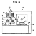
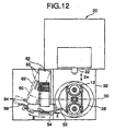
- a third embodiment of the present invention is, as shown in Fig. 11 of a front view and Fig. 12 of a plan view, adapted to take refuge by rotating the main body of the CMM 50 on rails 84 around a vertical axis 82 on the side of the M/C 20, as shown by the arrow B.
- This embodiment realizes a safe refuge movement and requires only a small occupation space compared with the second embodiment.
- the moving direction (Zm direction) of the work 10 relative to the cutter during cutting and the moving direction (Z-axis direction) of the prove 52 both are horizontal, thereby providing a high accuracy measurement, and an easy arrangement.
- the machining center and the three-dimensional coordinate-measuring machine each is not limited to a horizontal type.
- the APC 26 is of a two-position rotational type; however, the invention can also be employed for a machining tool, other than a machining center, comprising a three-position rotational type APC in which a machining position and two waiting positions are arranged at equi-angular position and the waiting positions are exchangeable by another method other than the rotational method.
- the invention is employed for the three-dimensional coordinate-measuring machine; however, it is apparent that the application of the invention is not limited to these embodiments, and that the invention can be similarly applied to a coordinate-measuring machine, which measures a three-dimensional shape of the work using the movement of the work with both an X-axis and a Y-axis fixed, and a two-dimensional coordinate-measuring machine which measures only a two-dimensional sectional shape of the work at a predetermined level.
Landscapes
- Engineering & Computer Science (AREA)
- Human Computer Interaction (AREA)
- Manufacturing & Machinery (AREA)
- Physics & Mathematics (AREA)
- General Physics & Mathematics (AREA)
- Automation & Control Theory (AREA)
- Machine Tool Sensing Apparatuses (AREA)
- Length Measuring Devices With Unspecified Measuring Means (AREA)
- Numerical Control (AREA)
Claims (11)
- Werkstückmeßverfahren, bei dem folgende Schritte ausgeführt werden:es wird ein Werkstück (10) in einer Warteposition auf einem Wechsler (26) angeordnet;der Wechsler (26) wird bewegt, um das Werkstück in oder in der Nähe einer Bearbeitungsposition anzuordnen;das Werkstück (10) wird mittels einer Werkzeugmaschine (20) bearbeitet;der Wechsler (26) wird bewegt, um das Werkstück (10) in die Warteposition zurückzubringen;danach wird ein Taststift (52) einer Koordinatenmeßmaschine (50) dicht an das Werkstück (10) in der Warteposition gebracht und dannwerden die Formen und Abmessungen des Werkstücks (10) in der Warteposition gemessen.
- Werkstückmeßverfahren nach Anspruch 1, bei dem die Richtung des Taststifts (52) der Koordinatenmeßmaschine (50), der sich zum Werkstück (10) hin bewegt, die gleiche wie die eines Werkzeugs (22) der Werkzeugmaschine (20) ist, das sich zum Werkstück (10) hin bewegt.
- Werkstückmeßverfahren nach Anspruch 2, bei dem die Richtung des Werkzeugs (22) der Werkzeugmaschine (20), das sich zum Werkstück (10) hin bewegt, und die des Taststifts (52) der Koordinatenmeßmaschine (50), der sich zum Werkstück (10) hin bewegt, beide horizontal sind.
- Werkstückmeßverfahren nach einem der Ansprüche 1 bis 3, bei dem die Koordinatenmeßmaschine (50) in der Lage ist, in eine solche Position auszuweichen, in der die Koordinatenmeßmaschine das Werkstück (10) nicht an einer Bewegung hindert.
- Werkstückmeßvorrichtung, die aufweist:einen Wechsler (26), durch den ein Werkstück (10) aus einer Warteposition in eine Position, die sich in oder nahe bei einer Bearbeitungsposition befindet, und zurück in die Warteposition bewegbar ist; und eine Koordinatenmeßmaschine (50) zum Verschieben eines Taststifts (52) der Koordinatenmeßmaschine (50) bis dicht an das Werkstück (10) in der Warteposition , um dadurch die Form und Abmessungen des Werkstücks (10) nach der Bearbeitung des Werkstücks (10) mit einer Werkzeugmaschine zu messen, wenn sich das Werkstück in der Bearbeitungsposition befindet.
- Werkstückmeßvorrichtung nach Anspruch 5, die ferner ein Ausweichmittel (80, 82, 84) aufweist, durch das bewirkt werden kann, daß die Koordinatenmeßmaschine (50) in eine solche Position ausweicht, in der die Koordinatenmeßmaschine das Werkstück (10) nicht an einer Bewegung hindert.
- Werkstückmeßvorrichtung nach Anspruch 6, bei der das Ausweichmittel (80) in der Lage ist zu bewirken, daß die Koordinatenmeßmaschine (50) in Form einer linearen Bewegung ausweicht.
- Werkstückmeßvorrichtung nach Anspruch 6, bei der das Ausweichmittel (82, 84) in der Lage ist zu bewirken, daß die Koordinatenmeßmaschine (50) in Form einer Drehbewegung ausweicht.
- Werkstückmeßvorrichtung nach einem der Ansprüche 5 bis 8, bei dem die Werkzeugmaschine (20) und die Koordinatenmeßmaschine (50) so ausgebildet sind, daß sie gegenseitig ein Meßfreigabesignal und ein Meßabschlußsignal austauschen, die sich beide auf die Bewegung des Werkstücks (10) durch den Wechsler (26) beziehen.
- Werkstückmeßvorrichtung nach Anspruch 9, bei der die Koordinatenmeßmaschine (50) eine Ausweichposition verläßt, nachdem sie ein Signal, das einen Wechselbewegungsabschluß signalisiert, von der Werkzeugmaschine (20) erhalten hat, und daß der Wechsler (26) das Bewegen des Werkstücks (10) beginnt, nachdem es ein Signal erhalten hat, das einen Abschluß der Ausweichbewegung der Koordinatenmeßmaschine signalisiert.
- Werkstückmeßvorrichtung nach einem der Ansprüche 5 bis 10, die ferner ein Mittel (24) zum Drehen des Werkstücks (10) aufweist, das in eine Meßposition gebracht worden ist.
Applications Claiming Priority (2)
| Application Number | Priority Date | Filing Date | Title |
|---|---|---|---|
| JP10127278A JPH11325869A (ja) | 1998-05-11 | 1998-05-11 | ワーク形状測定方法、装置及び座標測定機 |
| JP12727898 | 1998-05-11 |
Publications (3)
| Publication Number | Publication Date |
|---|---|
| EP0957417A2 EP0957417A2 (de) | 1999-11-17 |
| EP0957417A3 EP0957417A3 (de) | 2000-10-25 |
| EP0957417B1 true EP0957417B1 (de) | 2004-10-13 |
Family
ID=14956030
Family Applications (1)
| Application Number | Title | Priority Date | Filing Date |
|---|---|---|---|
| EP99303581A Expired - Lifetime EP0957417B1 (de) | 1998-05-11 | 1999-05-07 | Werkstückformmessungsverfahren und -vorrichtung, und Koördinatenmessmaschine |
Country Status (4)
| Country | Link |
|---|---|
| US (1) | US20020000047A1 (de) |
| EP (1) | EP0957417B1 (de) |
| JP (1) | JPH11325869A (de) |
| DE (1) | DE69921013T2 (de) |
Families Citing this family (13)
| Publication number | Priority date | Publication date | Assignee | Title |
|---|---|---|---|---|
| US6810600B1 (en) * | 2000-02-02 | 2004-11-02 | Unova Ip Corp. | Apparatus and method for monitoring alignment of a CNC machine spindle trunnion axis A |
| WO2003027783A1 (de) * | 2001-09-21 | 2003-04-03 | Thomas Fuchs | Verfahren zur bearbeitung von teilen sowie bearbeitungszentrum zur durchführung des verfahrens |
| EP2053345B1 (de) * | 2007-10-24 | 2010-06-02 | Klingelnberg AG | Messvorrichtung für schwere Werkstücke |
| US8250772B2 (en) * | 2008-02-07 | 2012-08-28 | Eaton Homer L | Spatial measurement and robotic arm device |
| US7587834B2 (en) * | 2008-02-07 | 2009-09-15 | Eaton Homer L | Motorized coordinate measuring device |
| JP5843531B2 (ja) | 2010-09-27 | 2016-01-13 | 株式会社ミツトヨ | 座標測定用ヘッドユニット及び座標測定機 |
| CN103673976A (zh) * | 2013-12-03 | 2014-03-26 | 上海卫星装备研究所 | 复合式精度测量坐标系的转换与统一方法及系统 |
| JP6577816B2 (ja) * | 2015-10-06 | 2019-09-18 | 株式会社ミツトヨ | 測定プローブ、及び測定プローブシステム |
| US10352679B2 (en) * | 2017-03-31 | 2019-07-16 | Mitutoyo Corporation | Compact coordinate measurement machine configuration with large working volume relative to size |
| JP6757391B2 (ja) * | 2018-11-19 | 2020-09-16 | Dmg森精機株式会社 | 測定方法 |
| JP7510244B2 (ja) * | 2018-11-26 | 2024-07-03 | 株式会社Subaru | 部品加工装置 |
| CN115026634A (zh) * | 2022-06-17 | 2022-09-09 | 江苏信息职业技术学院 | 一种机外电极毛坯最大实体测量机 |
| US11733255B1 (en) * | 2022-09-30 | 2023-08-22 | United Arab Emirates University | Industrial inspection system with interlock |
Citations (2)
| Publication number | Priority date | Publication date | Assignee | Title |
|---|---|---|---|---|
| GB2108715A (en) * | 1981-09-15 | 1983-05-18 | Renishaw Electrical Ltd | Method of operating a machine tool |
| DE3417741A1 (de) * | 1984-05-12 | 1985-11-14 | Mauser-Werke Oberndorf Gmbh, 7238 Oberndorf | Einrichtung zum messen von werkstuecken |
Family Cites Families (10)
| Publication number | Priority date | Publication date | Assignee | Title |
|---|---|---|---|---|
| US3839800A (en) * | 1968-08-29 | 1974-10-08 | Ibm | Method and apparatus for precisely contouring a work-piece imprecisely positioned on a fixture |
| US3823482A (en) * | 1972-06-19 | 1974-07-16 | Portage Machine Co | Inspection machine having right angle probe units |
| US5112131A (en) * | 1981-02-27 | 1992-05-12 | Diffracto, Ltd. | Controlled machining of combustion chambers, gears and other surfaces |
| JPS56139862A (en) * | 1980-04-03 | 1981-10-31 | Toshiba Mach Co Ltd | Operation control system of machine tool group |
| DE4005292A1 (de) * | 1990-02-20 | 1991-08-22 | Zeiss Carl Fa | Koordinatenmessgeraet |
| DE4102721A1 (de) * | 1991-01-30 | 1992-08-06 | Rosenthal Ag | Verfahren und vorrichtung zur erzeugung einer sollkontur an einem werkstueck |
| JP3386548B2 (ja) * | 1994-01-31 | 2003-03-17 | トヨタ自動車株式会社 | フィードバック式加工条件補正装置 |
| DE19604354A1 (de) * | 1996-02-07 | 1997-08-14 | Zeiss Carl Fa | Verfahren zur koordinatenmäßigen Vermessung von Werkstücken auf Bearbeitungsmaschinen |
| US6625894B1 (en) * | 2000-06-08 | 2003-09-30 | Kennametal Inc. | Position-adjusting device |
| US6519860B1 (en) * | 2000-10-19 | 2003-02-18 | Sandia Corporation | Position feedback control system |
-
1998
- 1998-05-11 JP JP10127278A patent/JPH11325869A/ja active Pending
-
1999
- 1999-05-07 EP EP99303581A patent/EP0957417B1/de not_active Expired - Lifetime
- 1999-05-07 DE DE69921013T patent/DE69921013T2/de not_active Expired - Fee Related
- 1999-05-11 US US09/309,264 patent/US20020000047A1/en not_active Abandoned
Patent Citations (2)
| Publication number | Priority date | Publication date | Assignee | Title |
|---|---|---|---|---|
| GB2108715A (en) * | 1981-09-15 | 1983-05-18 | Renishaw Electrical Ltd | Method of operating a machine tool |
| DE3417741A1 (de) * | 1984-05-12 | 1985-11-14 | Mauser-Werke Oberndorf Gmbh, 7238 Oberndorf | Einrichtung zum messen von werkstuecken |
Also Published As
| Publication number | Publication date |
|---|---|
| JPH11325869A (ja) | 1999-11-26 |
| EP0957417A2 (de) | 1999-11-17 |
| DE69921013D1 (de) | 2004-11-18 |
| US20020000047A1 (en) | 2002-01-03 |
| EP0957417A3 (de) | 2000-10-25 |
| DE69921013T2 (de) | 2005-11-24 |
Similar Documents
| Publication | Publication Date | Title |
|---|---|---|
| US5390128A (en) | Robotic processing and inspection system | |
| US5172464A (en) | Machine tool | |
| US4833764A (en) | Machine tool for machining workpieces by means of rotary tools | |
| EP0957417A2 (de) | Werkstückformmessungsverfahren und -vorrichtung, und Koördinatenmessmaschine | |
| US4302144A (en) | Work changing mechanism for machine tools | |
| EP2105814B1 (de) | Verfahren zur Steuerung einer Werkzeugmaschine und Vorrichtung dafür | |
| EP1116548A2 (de) | Werkzeugmaschine mit einer vertikal angeordneten Hauptspindel und Verfahren zur ihrer Herstellung | |
| EP0819499A2 (de) | Verfahren für Mehrspindelbearbeitungen | |
| JPS60207746A (ja) | 多面加工機械 | |
| JPS63229250A (ja) | マニシングセンタ | |
| US10228303B2 (en) | Flexible automation cell for performing secondary operations in concert with a machining center and roll check operations | |
| EP1203632B1 (de) | Werkzeugmaschine mit Werkzeugspositionskontrolle | |
| US6480757B1 (en) | Method of locating a workpiece on a computer numeric controlled machining system | |
| JPH07241714A (ja) | バリ取り装置 | |
| US4277880A (en) | Tracing milling machine with an automatic tool changer | |
| JP3464307B2 (ja) | Nc旋盤における干渉チェック方法 | |
| CA2147201C (en) | High accuracy machining station for a multiple spindle rotary indexing machine tool | |
| EP0121438A1 (de) | Flexibles Fertigungssystem und Verfahren | |
| CN2790669Y (zh) | 用于检查在一机床中的一主轴位置的装置 | |
| US4797991A (en) | Vertical machining center | |
| CN113894339A (zh) | 一种型材双端同步铣切加工中心及型材加工方法 | |
| EP0356513A1 (de) | Verfahren zur bestimmung der form eines bearbeiteten werkstückes | |
| JPH0569280A (ja) | マシニングセンタの測定装置およびワークの加工精度測定方法 | |
| CN108436610B (zh) | 机加工设备 | |
| CN114303109A (zh) | 数控机床的操作方法以及用于实施这样的方法的检测装置 |
Legal Events
| Date | Code | Title | Description |
|---|---|---|---|
| PUAI | Public reference made under article 153(3) epc to a published international application that has entered the european phase |
Free format text: ORIGINAL CODE: 0009012 |
|
| AK | Designated contracting states |
Kind code of ref document: A2 Designated state(s): DE FR GB IT |
|
| AX | Request for extension of the european patent |
Free format text: AL;LT;LV;MK;RO;SI |
|
| PUAL | Search report despatched |
Free format text: ORIGINAL CODE: 0009013 |
|
| AK | Designated contracting states |
Kind code of ref document: A3 Designated state(s): AT BE CH CY DE DK ES FI FR GB GR IE IT LI LU MC NL PT SE |
|
| AX | Request for extension of the european patent |
Free format text: AL;LT;LV;MK;RO;SI |
|
| 17P | Request for examination filed |
Effective date: 20010420 |
|
| AKX | Designation fees paid |
Free format text: DE FR GB IT |
|
| 17Q | First examination report despatched |
Effective date: 20030618 |
|
| RAP1 | Party data changed (applicant data changed or rights of an application transferred) |
Owner name: MORI SEIKI CO., LTD. Owner name: MITUTOYO CORPORATION |
|
| GRAP | Despatch of communication of intention to grant a patent |
Free format text: ORIGINAL CODE: EPIDOSNIGR1 |
|
| GRAS | Grant fee paid |
Free format text: ORIGINAL CODE: EPIDOSNIGR3 |
|
| GRAA | (expected) grant |
Free format text: ORIGINAL CODE: 0009210 |
|
| AK | Designated contracting states |
Kind code of ref document: B1 Designated state(s): DE FR GB IT |
|
| PG25 | Lapsed in a contracting state [announced via postgrant information from national office to epo] |
Ref country code: IT Free format text: LAPSE BECAUSE OF FAILURE TO SUBMIT A TRANSLATION OF THE DESCRIPTION OR TO PAY THE FEE WITHIN THE PRESCRIBED TIME-LIMIT;WARNING: LAPSES OF ITALIAN PATENTS WITH EFFECTIVE DATE BEFORE 2007 MAY HAVE OCCURRED AT ANY TIME BEFORE 2007. THE CORRECT EFFECTIVE DATE MAY BE DIFFERENT FROM THE ONE RECORDED. Effective date: 20041013 Ref country code: FR Free format text: LAPSE BECAUSE OF FAILURE TO SUBMIT A TRANSLATION OF THE DESCRIPTION OR TO PAY THE FEE WITHIN THE PRESCRIBED TIME-LIMIT Effective date: 20041013 |
|
| REG | Reference to a national code |
Ref country code: GB Ref legal event code: FG4D |
|
| REF | Corresponds to: |
Ref document number: 69921013 Country of ref document: DE Date of ref document: 20041118 Kind code of ref document: P |
|
| PG25 | Lapsed in a contracting state [announced via postgrant information from national office to epo] |
Ref country code: GB Free format text: LAPSE BECAUSE OF NON-PAYMENT OF DUE FEES Effective date: 20050507 |
|
| PLBI | Opposition filed |
Free format text: ORIGINAL CODE: 0009260 |
|
| PLAX | Notice of opposition and request to file observation + time limit sent |
Free format text: ORIGINAL CODE: EPIDOSNOBS2 |
|
| 26 | Opposition filed |
Opponent name: CARL ZEISS INDUSTRIELLE MESSTECHNIK GMBH Effective date: 20050701 |
|
| PG25 | Lapsed in a contracting state [announced via postgrant information from national office to epo] |
Ref country code: DE Free format text: LAPSE BECAUSE OF NON-PAYMENT OF DUE FEES Effective date: 20051201 |
|
| EN | Fr: translation not filed | ||
| GBPC | Gb: european patent ceased through non-payment of renewal fee |
Effective date: 20050507 |
|
| PLBD | Termination of opposition procedure: decision despatched |
Free format text: ORIGINAL CODE: EPIDOSNOPC1 |
|
| PLBM | Termination of opposition procedure: date of legal effect published |
Free format text: ORIGINAL CODE: 0009276 |
|
| STAA | Information on the status of an ep patent application or granted ep patent |
Free format text: STATUS: OPPOSITION PROCEDURE CLOSED |
|
| 27C | Opposition proceedings terminated |
Effective date: 20110923 |