EP4296130B1 - Hybrid vehicle control method and hybrid vehicle control device - Google Patents
Hybrid vehicle control method and hybrid vehicle control device Download PDFInfo
- Publication number
- EP4296130B1 EP4296130B1 EP21926061.9A EP21926061A EP4296130B1 EP 4296130 B1 EP4296130 B1 EP 4296130B1 EP 21926061 A EP21926061 A EP 21926061A EP 4296130 B1 EP4296130 B1 EP 4296130B1
- Authority
- EP
- European Patent Office
- Prior art keywords
- mode
- threshold value
- hybrid vehicle
- destination
- engine
- Prior art date
- Legal status (The legal status is an assumption and is not a legal conclusion. Google has not performed a legal analysis and makes no representation as to the accuracy of the status listed.)
- Active
Links
Images


Classifications
-
- B—PERFORMING OPERATIONS; TRANSPORTING
- B60—VEHICLES IN GENERAL
- B60K—ARRANGEMENT OR MOUNTING OF PROPULSION UNITS OR OF TRANSMISSIONS IN VEHICLES; ARRANGEMENT OR MOUNTING OF PLURAL DIVERSE PRIME-MOVERS IN VEHICLES; AUXILIARY DRIVES FOR VEHICLES; INSTRUMENTATION OR DASHBOARDS FOR VEHICLES; ARRANGEMENTS IN CONNECTION WITH COOLING, AIR INTAKE, GAS EXHAUST OR FUEL SUPPLY OF PROPULSION UNITS IN VEHICLES
- B60K6/00—Arrangement or mounting of plural diverse prime-movers for mutual or common propulsion, e.g. hybrid propulsion systems comprising electric motors and internal combustion engines
- B60K6/20—Arrangement or mounting of plural diverse prime-movers for mutual or common propulsion, e.g. hybrid propulsion systems comprising electric motors and internal combustion engines the prime-movers consisting of electric motors and internal combustion engines, e.g. HEVs
- B60K6/42—Arrangement or mounting of plural diverse prime-movers for mutual or common propulsion, e.g. hybrid propulsion systems comprising electric motors and internal combustion engines the prime-movers consisting of electric motors and internal combustion engines, e.g. HEVs characterised by the architecture of the hybrid electric vehicle
- B60K6/44—Series-parallel type
- B60K6/442—Series-parallel switching type
-
- B—PERFORMING OPERATIONS; TRANSPORTING
- B60—VEHICLES IN GENERAL
- B60K—ARRANGEMENT OR MOUNTING OF PROPULSION UNITS OR OF TRANSMISSIONS IN VEHICLES; ARRANGEMENT OR MOUNTING OF PLURAL DIVERSE PRIME-MOVERS IN VEHICLES; AUXILIARY DRIVES FOR VEHICLES; INSTRUMENTATION OR DASHBOARDS FOR VEHICLES; ARRANGEMENTS IN CONNECTION WITH COOLING, AIR INTAKE, GAS EXHAUST OR FUEL SUPPLY OF PROPULSION UNITS IN VEHICLES
- B60K6/00—Arrangement or mounting of plural diverse prime-movers for mutual or common propulsion, e.g. hybrid propulsion systems comprising electric motors and internal combustion engines
- B60K6/20—Arrangement or mounting of plural diverse prime-movers for mutual or common propulsion, e.g. hybrid propulsion systems comprising electric motors and internal combustion engines the prime-movers consisting of electric motors and internal combustion engines, e.g. HEVs
- B60K6/42—Arrangement or mounting of plural diverse prime-movers for mutual or common propulsion, e.g. hybrid propulsion systems comprising electric motors and internal combustion engines the prime-movers consisting of electric motors and internal combustion engines, e.g. HEVs characterised by the architecture of the hybrid electric vehicle
- B60K6/46—Series type
-
- B—PERFORMING OPERATIONS; TRANSPORTING
- B60—VEHICLES IN GENERAL
- B60L—PROPULSION OF ELECTRICALLY-PROPELLED VEHICLES; SUPPLYING ELECTRIC POWER FOR AUXILIARY EQUIPMENT OF ELECTRICALLY-PROPELLED VEHICLES; ELECTRODYNAMIC BRAKE SYSTEMS FOR VEHICLES IN GENERAL; MAGNETIC SUSPENSION OR LEVITATION FOR VEHICLES; MONITORING OPERATING VARIABLES OF ELECTRICALLY-PROPELLED VEHICLES; ELECTRIC SAFETY DEVICES FOR ELECTRICALLY-PROPELLED VEHICLES
- B60L50/00—Electric propulsion with power supplied within the vehicle
- B60L50/50—Electric propulsion with power supplied within the vehicle using propulsion power supplied by batteries or fuel cells
- B60L50/60—Electric propulsion with power supplied within the vehicle using propulsion power supplied by batteries or fuel cells using power supplied by batteries
- B60L50/61—Electric propulsion with power supplied within the vehicle using propulsion power supplied by batteries or fuel cells using power supplied by batteries by batteries charged by engine-driven generators, e.g. series hybrid electric vehicles
-
- B—PERFORMING OPERATIONS; TRANSPORTING
- B60—VEHICLES IN GENERAL
- B60L—PROPULSION OF ELECTRICALLY-PROPELLED VEHICLES; SUPPLYING ELECTRIC POWER FOR AUXILIARY EQUIPMENT OF ELECTRICALLY-PROPELLED VEHICLES; ELECTRODYNAMIC BRAKE SYSTEMS FOR VEHICLES IN GENERAL; MAGNETIC SUSPENSION OR LEVITATION FOR VEHICLES; MONITORING OPERATING VARIABLES OF ELECTRICALLY-PROPELLED VEHICLES; ELECTRIC SAFETY DEVICES FOR ELECTRICALLY-PROPELLED VEHICLES
- B60L58/00—Methods or circuit arrangements for monitoring or controlling batteries or fuel cells, specially adapted for electric vehicles
- B60L58/10—Methods or circuit arrangements for monitoring or controlling batteries or fuel cells, specially adapted for electric vehicles for monitoring or controlling batteries
- B60L58/12—Methods or circuit arrangements for monitoring or controlling batteries or fuel cells, specially adapted for electric vehicles for monitoring or controlling batteries responding to state of charge [SoC]
- B60L58/13—Maintaining the SoC within a determined range
-
- B—PERFORMING OPERATIONS; TRANSPORTING
- B60—VEHICLES IN GENERAL
- B60W—CONJOINT CONTROL OF VEHICLE SUB-UNITS OF DIFFERENT TYPE OR DIFFERENT FUNCTION; CONTROL SYSTEMS SPECIALLY ADAPTED FOR HYBRID VEHICLES; ROAD VEHICLE DRIVE CONTROL SYSTEMS FOR PURPOSES NOT RELATED TO THE CONTROL OF A PARTICULAR SUB-UNIT
- B60W10/00—Conjoint control of vehicle sub-units of different type or different function
- B60W10/04—Conjoint control of vehicle sub-units of different type or different function including control of propulsion units
- B60W10/06—Conjoint control of vehicle sub-units of different type or different function including control of propulsion units including control of combustion engines
-
- B—PERFORMING OPERATIONS; TRANSPORTING
- B60—VEHICLES IN GENERAL
- B60W—CONJOINT CONTROL OF VEHICLE SUB-UNITS OF DIFFERENT TYPE OR DIFFERENT FUNCTION; CONTROL SYSTEMS SPECIALLY ADAPTED FOR HYBRID VEHICLES; ROAD VEHICLE DRIVE CONTROL SYSTEMS FOR PURPOSES NOT RELATED TO THE CONTROL OF A PARTICULAR SUB-UNIT
- B60W10/00—Conjoint control of vehicle sub-units of different type or different function
- B60W10/04—Conjoint control of vehicle sub-units of different type or different function including control of propulsion units
- B60W10/08—Conjoint control of vehicle sub-units of different type or different function including control of propulsion units including control of electric propulsion units, e.g. motors or generators
-
- B—PERFORMING OPERATIONS; TRANSPORTING
- B60—VEHICLES IN GENERAL
- B60W—CONJOINT CONTROL OF VEHICLE SUB-UNITS OF DIFFERENT TYPE OR DIFFERENT FUNCTION; CONTROL SYSTEMS SPECIALLY ADAPTED FOR HYBRID VEHICLES; ROAD VEHICLE DRIVE CONTROL SYSTEMS FOR PURPOSES NOT RELATED TO THE CONTROL OF A PARTICULAR SUB-UNIT
- B60W20/00—Control systems specially adapted for hybrid vehicles
- B60W20/10—Controlling the power contribution of each of the prime movers to meet required power demand
- B60W20/11—Controlling the power contribution of each of the prime movers to meet required power demand using model predictive control [MPC] strategies, i.e. control methods based on models predicting performance
-
- B—PERFORMING OPERATIONS; TRANSPORTING
- B60—VEHICLES IN GENERAL
- B60W—CONJOINT CONTROL OF VEHICLE SUB-UNITS OF DIFFERENT TYPE OR DIFFERENT FUNCTION; CONTROL SYSTEMS SPECIALLY ADAPTED FOR HYBRID VEHICLES; ROAD VEHICLE DRIVE CONTROL SYSTEMS FOR PURPOSES NOT RELATED TO THE CONTROL OF A PARTICULAR SUB-UNIT
- B60W20/00—Control systems specially adapted for hybrid vehicles
- B60W20/10—Controlling the power contribution of each of the prime movers to meet required power demand
- B60W20/12—Controlling the power contribution of each of the prime movers to meet required power demand using control strategies taking into account route information
-
- B—PERFORMING OPERATIONS; TRANSPORTING
- B60—VEHICLES IN GENERAL
- B60W—CONJOINT CONTROL OF VEHICLE SUB-UNITS OF DIFFERENT TYPE OR DIFFERENT FUNCTION; CONTROL SYSTEMS SPECIALLY ADAPTED FOR HYBRID VEHICLES; ROAD VEHICLE DRIVE CONTROL SYSTEMS FOR PURPOSES NOT RELATED TO THE CONTROL OF A PARTICULAR SUB-UNIT
- B60W20/00—Control systems specially adapted for hybrid vehicles
- B60W20/10—Controlling the power contribution of each of the prime movers to meet required power demand
- B60W20/13—Controlling the power contribution of each of the prime movers to meet required power demand in order to stay within battery power input or output limits; in order to prevent overcharging or battery depletion
- B60W20/14—Controlling the power contribution of each of the prime movers to meet required power demand in order to stay within battery power input or output limits; in order to prevent overcharging or battery depletion in conjunction with braking regeneration
-
- B—PERFORMING OPERATIONS; TRANSPORTING
- B60—VEHICLES IN GENERAL
- B60W—CONJOINT CONTROL OF VEHICLE SUB-UNITS OF DIFFERENT TYPE OR DIFFERENT FUNCTION; CONTROL SYSTEMS SPECIALLY ADAPTED FOR HYBRID VEHICLES; ROAD VEHICLE DRIVE CONTROL SYSTEMS FOR PURPOSES NOT RELATED TO THE CONTROL OF A PARTICULAR SUB-UNIT
- B60W20/00—Control systems specially adapted for hybrid vehicles
- B60W20/40—Controlling the engagement or disengagement of prime movers, e.g. for transition between prime movers
-
- B—PERFORMING OPERATIONS; TRANSPORTING
- B60—VEHICLES IN GENERAL
- B60W—CONJOINT CONTROL OF VEHICLE SUB-UNITS OF DIFFERENT TYPE OR DIFFERENT FUNCTION; CONTROL SYSTEMS SPECIALLY ADAPTED FOR HYBRID VEHICLES; ROAD VEHICLE DRIVE CONTROL SYSTEMS FOR PURPOSES NOT RELATED TO THE CONTROL OF A PARTICULAR SUB-UNIT
- B60W30/00—Purposes of road vehicle drive control systems not related to the control of a particular sub-unit, e.g. of systems using conjoint control of vehicle sub-units
- B60W30/18—Propelling the vehicle
- B60W30/18009—Propelling the vehicle related to particular drive situations
- B60W30/181—Preparing for stopping
-
- B—PERFORMING OPERATIONS; TRANSPORTING
- B60—VEHICLES IN GENERAL
- B60W—CONJOINT CONTROL OF VEHICLE SUB-UNITS OF DIFFERENT TYPE OR DIFFERENT FUNCTION; CONTROL SYSTEMS SPECIALLY ADAPTED FOR HYBRID VEHICLES; ROAD VEHICLE DRIVE CONTROL SYSTEMS FOR PURPOSES NOT RELATED TO THE CONTROL OF A PARTICULAR SUB-UNIT
- B60W30/00—Purposes of road vehicle drive control systems not related to the control of a particular sub-unit, e.g. of systems using conjoint control of vehicle sub-units
- B60W30/18—Propelling the vehicle
- B60W30/188—Controlling power parameters of the driveline, e.g. determining the required power
- B60W30/1882—Controlling power parameters of the driveline, e.g. determining the required power characterised by the working point of the engine, e.g. by using engine output chart
-
- B—PERFORMING OPERATIONS; TRANSPORTING
- B60—VEHICLES IN GENERAL
- B60W—CONJOINT CONTROL OF VEHICLE SUB-UNITS OF DIFFERENT TYPE OR DIFFERENT FUNCTION; CONTROL SYSTEMS SPECIALLY ADAPTED FOR HYBRID VEHICLES; ROAD VEHICLE DRIVE CONTROL SYSTEMS FOR PURPOSES NOT RELATED TO THE CONTROL OF A PARTICULAR SUB-UNIT
- B60W30/00—Purposes of road vehicle drive control systems not related to the control of a particular sub-unit, e.g. of systems using conjoint control of vehicle sub-units
- B60W30/18—Propelling the vehicle
- B60W30/192—Mitigating problems related to power-up or power-down of the driveline, e.g. start-up of a cold engine
- B60W30/194—Mitigating problems related to power-up or power-down of the driveline, e.g. start-up of a cold engine related to low temperature conditions, e.g. high viscosity of hydraulic fluid
-
- B—PERFORMING OPERATIONS; TRANSPORTING
- B60—VEHICLES IN GENERAL
- B60W—CONJOINT CONTROL OF VEHICLE SUB-UNITS OF DIFFERENT TYPE OR DIFFERENT FUNCTION; CONTROL SYSTEMS SPECIALLY ADAPTED FOR HYBRID VEHICLES; ROAD VEHICLE DRIVE CONTROL SYSTEMS FOR PURPOSES NOT RELATED TO THE CONTROL OF A PARTICULAR SUB-UNIT
- B60W40/00—Estimation or calculation of non-directly measurable driving parameters for road vehicle drive control systems not related to the control of a particular sub unit, e.g. by using mathematical models
- B60W40/02—Estimation or calculation of non-directly measurable driving parameters for road vehicle drive control systems not related to the control of a particular sub unit, e.g. by using mathematical models related to ambient conditions
-
- B—PERFORMING OPERATIONS; TRANSPORTING
- B60—VEHICLES IN GENERAL
- B60W—CONJOINT CONTROL OF VEHICLE SUB-UNITS OF DIFFERENT TYPE OR DIFFERENT FUNCTION; CONTROL SYSTEMS SPECIALLY ADAPTED FOR HYBRID VEHICLES; ROAD VEHICLE DRIVE CONTROL SYSTEMS FOR PURPOSES NOT RELATED TO THE CONTROL OF A PARTICULAR SUB-UNIT
- B60W50/00—Details of control systems for road vehicle drive control not related to the control of a particular sub-unit, e.g. process diagnostic or vehicle driver interfaces
- B60W50/0097—Predicting future conditions
-
- B—PERFORMING OPERATIONS; TRANSPORTING
- B60—VEHICLES IN GENERAL
- B60L—PROPULSION OF ELECTRICALLY-PROPELLED VEHICLES; SUPPLYING ELECTRIC POWER FOR AUXILIARY EQUIPMENT OF ELECTRICALLY-PROPELLED VEHICLES; ELECTRODYNAMIC BRAKE SYSTEMS FOR VEHICLES IN GENERAL; MAGNETIC SUSPENSION OR LEVITATION FOR VEHICLES; MONITORING OPERATING VARIABLES OF ELECTRICALLY-PROPELLED VEHICLES; ELECTRIC SAFETY DEVICES FOR ELECTRICALLY-PROPELLED VEHICLES
- B60L2240/00—Control parameters of input or output; Target parameters
- B60L2240/40—Drive Train control parameters
- B60L2240/44—Drive Train control parameters related to combustion engines
- B60L2240/445—Temperature
-
- B—PERFORMING OPERATIONS; TRANSPORTING
- B60—VEHICLES IN GENERAL
- B60L—PROPULSION OF ELECTRICALLY-PROPELLED VEHICLES; SUPPLYING ELECTRIC POWER FOR AUXILIARY EQUIPMENT OF ELECTRICALLY-PROPELLED VEHICLES; ELECTRODYNAMIC BRAKE SYSTEMS FOR VEHICLES IN GENERAL; MAGNETIC SUSPENSION OR LEVITATION FOR VEHICLES; MONITORING OPERATING VARIABLES OF ELECTRICALLY-PROPELLED VEHICLES; ELECTRIC SAFETY DEVICES FOR ELECTRICALLY-PROPELLED VEHICLES
- B60L2240/00—Control parameters of input or output; Target parameters
- B60L2240/60—Navigation input
- B60L2240/62—Vehicle position
- B60L2240/622—Vehicle position by satellite navigation
-
- B—PERFORMING OPERATIONS; TRANSPORTING
- B60—VEHICLES IN GENERAL
- B60L—PROPULSION OF ELECTRICALLY-PROPELLED VEHICLES; SUPPLYING ELECTRIC POWER FOR AUXILIARY EQUIPMENT OF ELECTRICALLY-PROPELLED VEHICLES; ELECTRODYNAMIC BRAKE SYSTEMS FOR VEHICLES IN GENERAL; MAGNETIC SUSPENSION OR LEVITATION FOR VEHICLES; MONITORING OPERATING VARIABLES OF ELECTRICALLY-PROPELLED VEHICLES; ELECTRIC SAFETY DEVICES FOR ELECTRICALLY-PROPELLED VEHICLES
- B60L2240/00—Control parameters of input or output; Target parameters
- B60L2240/60—Navigation input
- B60L2240/66—Ambient conditions
- B60L2240/662—Temperature
-
- B—PERFORMING OPERATIONS; TRANSPORTING
- B60—VEHICLES IN GENERAL
- B60L—PROPULSION OF ELECTRICALLY-PROPELLED VEHICLES; SUPPLYING ELECTRIC POWER FOR AUXILIARY EQUIPMENT OF ELECTRICALLY-PROPELLED VEHICLES; ELECTRODYNAMIC BRAKE SYSTEMS FOR VEHICLES IN GENERAL; MAGNETIC SUSPENSION OR LEVITATION FOR VEHICLES; MONITORING OPERATING VARIABLES OF ELECTRICALLY-PROPELLED VEHICLES; ELECTRIC SAFETY DEVICES FOR ELECTRICALLY-PROPELLED VEHICLES
- B60L2260/00—Operating Modes
- B60L2260/40—Control modes
- B60L2260/50—Control modes by future state prediction
- B60L2260/54—Energy consumption estimation
-
- B—PERFORMING OPERATIONS; TRANSPORTING
- B60—VEHICLES IN GENERAL
- B60W—CONJOINT CONTROL OF VEHICLE SUB-UNITS OF DIFFERENT TYPE OR DIFFERENT FUNCTION; CONTROL SYSTEMS SPECIALLY ADAPTED FOR HYBRID VEHICLES; ROAD VEHICLE DRIVE CONTROL SYSTEMS FOR PURPOSES NOT RELATED TO THE CONTROL OF A PARTICULAR SUB-UNIT
- B60W10/00—Conjoint control of vehicle sub-units of different type or different function
- B60W10/24—Conjoint control of vehicle sub-units of different type or different function including control of energy storage means
- B60W10/26—Conjoint control of vehicle sub-units of different type or different function including control of energy storage means for electrical energy, e.g. batteries or capacitors
-
- B—PERFORMING OPERATIONS; TRANSPORTING
- B60—VEHICLES IN GENERAL
- B60W—CONJOINT CONTROL OF VEHICLE SUB-UNITS OF DIFFERENT TYPE OR DIFFERENT FUNCTION; CONTROL SYSTEMS SPECIALLY ADAPTED FOR HYBRID VEHICLES; ROAD VEHICLE DRIVE CONTROL SYSTEMS FOR PURPOSES NOT RELATED TO THE CONTROL OF A PARTICULAR SUB-UNIT
- B60W50/00—Details of control systems for road vehicle drive control not related to the control of a particular sub-unit, e.g. process diagnostic or vehicle driver interfaces
- B60W50/08—Interaction between the driver and the control system
- B60W50/14—Means for informing the driver, warning the driver or prompting a driver intervention
- B60W2050/146—Display means
-
- B—PERFORMING OPERATIONS; TRANSPORTING
- B60—VEHICLES IN GENERAL
- B60W—CONJOINT CONTROL OF VEHICLE SUB-UNITS OF DIFFERENT TYPE OR DIFFERENT FUNCTION; CONTROL SYSTEMS SPECIALLY ADAPTED FOR HYBRID VEHICLES; ROAD VEHICLE DRIVE CONTROL SYSTEMS FOR PURPOSES NOT RELATED TO THE CONTROL OF A PARTICULAR SUB-UNIT
- B60W2510/00—Input parameters relating to a particular sub-units
- B60W2510/06—Combustion engines, Gas turbines
- B60W2510/0676—Engine temperature
-
- B—PERFORMING OPERATIONS; TRANSPORTING
- B60—VEHICLES IN GENERAL
- B60W—CONJOINT CONTROL OF VEHICLE SUB-UNITS OF DIFFERENT TYPE OR DIFFERENT FUNCTION; CONTROL SYSTEMS SPECIALLY ADAPTED FOR HYBRID VEHICLES; ROAD VEHICLE DRIVE CONTROL SYSTEMS FOR PURPOSES NOT RELATED TO THE CONTROL OF A PARTICULAR SUB-UNIT
- B60W2510/00—Input parameters relating to a particular sub-units
- B60W2510/24—Energy storage means
- B60W2510/242—Energy storage means for electrical energy
- B60W2510/244—Charge state
-
- B—PERFORMING OPERATIONS; TRANSPORTING
- B60—VEHICLES IN GENERAL
- B60W—CONJOINT CONTROL OF VEHICLE SUB-UNITS OF DIFFERENT TYPE OR DIFFERENT FUNCTION; CONTROL SYSTEMS SPECIALLY ADAPTED FOR HYBRID VEHICLES; ROAD VEHICLE DRIVE CONTROL SYSTEMS FOR PURPOSES NOT RELATED TO THE CONTROL OF A PARTICULAR SUB-UNIT
- B60W2552/00—Input parameters relating to infrastructure
- B60W2552/15—Road slope, i.e. the inclination of a road segment in the longitudinal direction
-
- B—PERFORMING OPERATIONS; TRANSPORTING
- B60—VEHICLES IN GENERAL
- B60W—CONJOINT CONTROL OF VEHICLE SUB-UNITS OF DIFFERENT TYPE OR DIFFERENT FUNCTION; CONTROL SYSTEMS SPECIALLY ADAPTED FOR HYBRID VEHICLES; ROAD VEHICLE DRIVE CONTROL SYSTEMS FOR PURPOSES NOT RELATED TO THE CONTROL OF A PARTICULAR SUB-UNIT
- B60W2555/00—Input parameters relating to exterior conditions, not covered by groups B60W2552/00, B60W2554/00
- B60W2555/20—Ambient conditions, e.g. wind or rain
-
- B—PERFORMING OPERATIONS; TRANSPORTING
- B60—VEHICLES IN GENERAL
- B60W—CONJOINT CONTROL OF VEHICLE SUB-UNITS OF DIFFERENT TYPE OR DIFFERENT FUNCTION; CONTROL SYSTEMS SPECIALLY ADAPTED FOR HYBRID VEHICLES; ROAD VEHICLE DRIVE CONTROL SYSTEMS FOR PURPOSES NOT RELATED TO THE CONTROL OF A PARTICULAR SUB-UNIT
- B60W2556/00—Input parameters relating to data
- B60W2556/45—External transmission of data to or from the vehicle
- B60W2556/50—External transmission of data to or from the vehicle of positioning data, e.g. GPS [Global Positioning System] data
-
- B—PERFORMING OPERATIONS; TRANSPORTING
- B60—VEHICLES IN GENERAL
- B60W—CONJOINT CONTROL OF VEHICLE SUB-UNITS OF DIFFERENT TYPE OR DIFFERENT FUNCTION; CONTROL SYSTEMS SPECIALLY ADAPTED FOR HYBRID VEHICLES; ROAD VEHICLE DRIVE CONTROL SYSTEMS FOR PURPOSES NOT RELATED TO THE CONTROL OF A PARTICULAR SUB-UNIT
- B60W2710/00—Output or target parameters relating to a particular sub-units
- B60W2710/06—Combustion engines, Gas turbines
- B60W2710/0688—Engine temperature
-
- B—PERFORMING OPERATIONS; TRANSPORTING
- B60—VEHICLES IN GENERAL
- B60W—CONJOINT CONTROL OF VEHICLE SUB-UNITS OF DIFFERENT TYPE OR DIFFERENT FUNCTION; CONTROL SYSTEMS SPECIALLY ADAPTED FOR HYBRID VEHICLES; ROAD VEHICLE DRIVE CONTROL SYSTEMS FOR PURPOSES NOT RELATED TO THE CONTROL OF A PARTICULAR SUB-UNIT
- B60W2710/00—Output or target parameters relating to a particular sub-units
- B60W2710/24—Energy storage means
- B60W2710/242—Energy storage means for electrical energy
- B60W2710/244—Charge state
-
- B—PERFORMING OPERATIONS; TRANSPORTING
- B60—VEHICLES IN GENERAL
- B60Y—INDEXING SCHEME RELATING TO ASPECTS CROSS-CUTTING VEHICLE TECHNOLOGY
- B60Y2200/00—Type of vehicle
- B60Y2200/90—Vehicles comprising electric prime movers
- B60Y2200/92—Hybrid vehicles
-
- Y—GENERAL TAGGING OF NEW TECHNOLOGICAL DEVELOPMENTS; GENERAL TAGGING OF CROSS-SECTIONAL TECHNOLOGIES SPANNING OVER SEVERAL SECTIONS OF THE IPC; TECHNICAL SUBJECTS COVERED BY FORMER USPC CROSS-REFERENCE ART COLLECTIONS [XRACs] AND DIGESTS
- Y02—TECHNOLOGIES OR APPLICATIONS FOR MITIGATION OR ADAPTATION AGAINST CLIMATE CHANGE
- Y02T—CLIMATE CHANGE MITIGATION TECHNOLOGIES RELATED TO TRANSPORTATION
- Y02T10/00—Road transport of goods or passengers
- Y02T10/60—Other road transportation technologies with climate change mitigation effect
- Y02T10/62—Hybrid vehicles
Definitions
- the present invention relates to control of a hybrid vehicle.
- JP 2017-81416 A discloses, as control of a hybrid vehicle, control that prioritizes traveling by electric energy in order to reduce a state of charge of a battery when reaching a parking spot when there is the parking spot on a traveling route where a parking time is expected to be longer than a threshold value.
- a reason for reducing the state of charge is to increase utilization efficiency of "cold charging" in which the battery is charged using a driving force of an engine that drives for warming up during traveling after the hybrid vehicle is parked for a long time.
- US 2019/0168739 discloses a hybrid vehicle and a control device mounted thereon.
- US 2020/0156619 A1 discloses a control device for hybrid vehicle, a control method for hybrid vehicle and a recording medium.
- DE 10 2015 014 875 A1 discloses a method for operating a hybrid vehicle.
- DE 10 2019 111 653 A1 discloses a method and systems for a hybrid vehicle.
- an engine coolant temperature decreases.
- the engine coolant temperature reaches a lower limit value at which performance of a heating device or a defroster device can be ensured while the engine is stopped, the engine is restarted. That is, in the control of the patent literature, as the engine coolant temperature drops, the engine may restart, and it may be impossible to lower the state of charge as intended.
- the engine stopping state is maintained even after the engine coolant temperature reaches the lower limit value, the performance of the heating device or the defroster device is degraded.
- an object of the present invention is to reduce a state of charge before a target position without degrading performance of a heating device or a defroster device.
- a method for controlling a hybrid vehicle including an engine, a power generating motor generator that is driven by the engine and generates electric power, a traveling motor generator, and a battery that is charged by the electric power generated by the power generating motor generator and supplies the electric power to the traveling motor generator.
- a controller executes a state of charge reducing control in which a state of charge of the battery at a time point at which the hybrid vehicle reaches a destination is lower than an upper limit state of charge by providing a section for executing an EV mode in which the engine is stopped and the hybrid vehicle travels by the traveling motor generator until the hybrid vehicle reaches the destination.
- the controller starts the EV mode when the EV mode is continuable to the destination and executes the EV mode until the hybrid vehicle reaches the destination, and if the estimated value of the lowest temperature is lower than the first threshold value, the controller shortens a section for executing the EV mode compared to when the estimated value of the lowest temperature is equal to or higher than the first threshold value.
- FIG. 1 is a schematic configuration diagram of a hybrid vehicle 100.
- FIG. 2 is a schematic configuration diagram of a controller 20.
- the hybrid vehicle includes an engine 1, a power generating motor generator 2, a traveling motor generator 3, a first inverter 4, a second inverter 5, a battery 6, a differential mechanism 7, a driving wheel 8, and a controller 20.
- the hybrid vehicle 100 is referred to as a vehicle 100
- the motor generator is referred to as MG.
- the engine 1 is an internal combustion engine such as a gasoline engine or a diesel engine.
- the engine 1 is connected to the power generating MG2 via a speed reduction mechanism (not shown).
- the power generating MG2 is driven by the engine 1 and generates electric power.
- the traveling MG3 is connected to the driving wheel 8 via the differential mechanism 7.
- the traveling MG3 drives the vehicle 100 and performs regenerative power generation during deceleration.
- the power generating MG2 and the traveling MG3 form a highvoltage circuit 9 together with the first inverter 4, the second inverter 5, the battery 6, and the like.
- the first inverter 4 is used for controlling the power generating MG2, and the second inverter 5 is used for controlling the traveling MG3.
- Each of the first inverter 4 and the second inverter 5 generates a three-phase alternating current based on a command from the controller 20, and applies the generated three-phase alternating current to the corresponding MG of the power generating MG2 and the traveling MG3.
- the first inverter 4 and the second inverter 5 may be integrated.
- the battery 6 constitutes a power source of the power generating MG2 and the traveling MG3.
- the battery 6 is charged by the electric power generated by the power generating MG2 and electric power regeneratively generated by the traveling MG3.
- the controller 20 is implemented by one or a plurality of microcomputers including a central processing unit (CPU), a read-only memory (ROM), a random access memory (RAM), and an input/output interface (I/O interface).
- the controller 20 integrally controls the engine 1, the first inverter 4, the second inverter 5, and the like by executing a program stored in the ROM or the RAM by the CPU.
- the controller 20 receives signals from an SOC sensor 22 that detects a state of charge (SOC) of the battery 6, a coolant temperature sensor 23 that detects a temperature of a coolant in the engine 1, an outside air temperature sensor 24 that detects a temperature outside the vehicle, and various sensors and switches. Further, various information, which will be described later, is input to the controller 20 from the navigation system 21. These signals and information are used for control performed by the controller 20.
- SOC state of charge
- the controller 20 has an EV mode and a series hybrid mode (hereinafter referred to as a series HEV mode) as traveling modes of the vehicle 100.
- the EV mode is a mode in which the engine 1 is stopped, the traveling MG3 is driven by the electric power supplied from the battery 6, and the vehicle travels by a driving force only from the traveling MG3.
- the series HEV mode is a mode in which the engine 1 is driven to drive the traveling MG3 while generating the electric power by the power generating MG2.
- the controller 20 selects a traveling mode based on an accelerator position (accelerator opening degree) APO, a brake pedal depression force BPF, and a vehicle speed VSP with reference to a traveling mode selection map (not shown), and drives the engine 1 and the traveling MG3 so as to achieve the selected traveling mode.
- a traveling mode selection map (not shown)
- a hybrid system of the vehicle 100 shown in FIG. 1 is a series hybrid system in which the engine 1 is exclusively used for driving the power generating MG2 and the driving wheel 8 is exclusively driven by the traveling MG3.
- the present embodiment is also applicable to a parallel hybrid system in which the engine 1 is also used for driving the driving wheel 8.
- the parallel hybrid system similarly to the series hybrid system, the engine 1 is stopped in the EV mode, and the engine 1 is operated in the HEV mode.
- FIG. 2 is a schematic configuration diagram of the controller 20.
- FIG. 2 shows a part of functions of the controller 20 as a block diagram, and each block does not mean a physical configuration.
- the controller 20 includes an event detection unit 20A, an energy estimation unit 20B, an engine coolant temperature estimation unit 20C, a target SOC calculation unit 20D, an HEV energy management unit 20E, and an HMI management unit 20F.
- Map information for each predetermined section is input from the navigation system 21 to the event detection unit 20A and the energy estimation unit 20B.
- the map information includes, for example, a road gradient, a statistical average vehicle speed, a speed limit, a distance to a destination, and the like.
- the event detection unit 20A and the energy estimation unit 20B also receive information related to a function activated by the driver via an interface device such as a display.
- the event detection unit 20A detects event information on a traveling route to the destination based on the input information.
- the event information is, for example, information related to an event affecting control of output, a speed, and the like of the vehicle 100, such as the presence or absence of an uphill road or a downhill road, the presence or absence of an intersection, a crosswalk, or the like, whether a road is an expressway, whether the vehicle 100 has reached the destination, and the like.
- These pieces of event information are output to the energy estimation unit 20B and the engine coolant temperature estimation unit 20C.
- the energy estimation unit 20B estimates power usage, a regeneration amount, and an electric power generation amount until the vehicle reaches the destination. An estimation result is output to the target SOC calculation unit 20D.
- the engine coolant temperature estimation unit 20C estimates a transition of an engine coolant temperature Tcl until the vehicle reaches the destination based on the event information detected by the event detection unit 20A, a detection value of the coolant temperature sensor 23, and a detection value of the outside air temperature sensor 24. The estimation result is output to the HEV energy management unit 20E.
- the target SOC calculation unit 20D calculates a target SOC of the battery 6 based on the estimation result obtained by the energy estimation unit 20B. For example, when there is an uphill road or an expressway ahead, an upper limit SOC or an SOC close to the upper limit SOC is set as the target SOC in order to cope with high output. Further, when there is a downhill road ahead, since a margin for receiving regenerative electric power on the downhill road is provided, the target SOC before entering the downhill road is set low. The target SOC is output to the HEV energy management unit 20E.
- the HEV energy management unit 20E determines operation and stop, and an operating point of the engine 1, an operating point of the traveling MG3, and the like based on the input information, and controls the engine 1 and the traveling MG3 based on these. Information such as the operating point of the engine 1 is output to the HMI management unit 20F.
- the engine 1 basically operates and stops in accordance with the selected traveling mode. However, even if the HEV mode is selected, when the SOC of the battery 6 reaches the upper limit SOC, the engine 1 is stopped, and even if the EV mode is selected, when the SOC reaches a lower limit SOC, the engine 1 is operated.
- the upper limit SOC and the lower limit SOC are set in advance from the viewpoint of preventing deterioration of the battery 6. Further, in a case in which the EV mode is selected, when the engine coolant temperature Tcl has decreased to a threshold value, the engine 1 is operated. This is to ensure functions of the defroster device and the heating device using an engine coolant as a heat source.
- control of operating and stopping the engine 1 according to the SOC of the battery 6 and the engine coolant temperature Tcl is referred to as normal control.
- the HMI management unit 20F generates information on an operation state of each application based on the information determined by the HEV energy management unit 20E, and displays the information on the interface device such as a display via the navigation system 21.
- the controller 20 operates the engine 1 to warm up, that is, to raise temperatures of the engine 1 main body and the engine coolant, promote activation of an exhaust gas purification catalyst, and the like.
- the battery 6 is also charged.
- the SOC of the battery 6 reaches the upper limit SOC at a start of the system, the battery 6 cannot be charged during the warmup.
- the controller 20 positively performs the EV mode in order to sufficiently reduce the SOC of the battery 6 before the vehicle reaches the destination.
- the control of positively performing the EV mode in order to sufficiently reduce the SOC of the battery 6 is referred to as state of charge reducing control.
- the case in which the vehicle is expected to be parked for a long time is, for example, a case in which the destination is home, that is, a case in which the driver comes home from an outing destination, a case in which the destination is an accommodation facility of a travel destination, or the like.
- the engine coolant temperature Tcl decreases. Therefore, when a time for which the EV mode is performed becomes long, performance of the heating device and the defroster device may be degraded due to the decrease in the engine coolant temperature Tel. According to the normal control described above, since the engine 1 is operated when the engine coolant temperature Tel decreases, performance degradation of the heating device and the like can be prevented, but at the same time, since the power generating MG2 also generates the electric power, the SOC of the battery 6 cannot be sufficiently reduced.
- the controller 20 executes control to be described below in order to sufficiently reduce the SOC of the battery 6 before the vehicle reaches the destination and to prevent the performance degradation of the heating device and the defroster device.
- FIG. 3 is a flowchart showing a control routine of the state of state of charge reducing control in the present embodiment.
- the present control routine in a case in which it is necessary to reduce the SOC of the battery 6 before the vehicle reaches the destination, when the EV mode is executed from there to the destination, it is estimated how far the engine coolant temperature Tcl is decreased, and when it is estimated that the engine coolant temperature Tcl falls below a first threshold value Tcl1, a section in which the EV mode is performed is reduced.
- the present control routine starts when detailed event information up to the destination is input from the navigation system 21. Since the detailed event information is input, for example, for each section of several kilometers, the present control routine is started at a position several kilometers from the destination.
- a travellable distance in the EV mode under a predetermined travel condition may be obtained in advance based on a capacity of the battery 6, and the present control routine may be started when a distance to the destination is equal to or less than the travellable distance.
- the engine 1 is operated under the above-described normal control until the EV mode is started by the present control routine.
- the present control routine is based on a premise that the engine 1 is in the cold machine state due to parking for a long time after the vehicle reaches the destination, when the destination set by the driver is a place where it is clear that the parking for a long time is not performed, it is not necessary to execute the present control routine.
- a description will be made in accordance with the steps.
- step S100 the controller 20 determines whether an outside air temperature is higher than a first outside air temperature, which is a threshold value for determination, and when the outside air temperature is higher than the first outside air temperature, a process of step S101 is executed, and when the outside air temperature is below the first outside air temperature, this routine ends.
- the first outside air temperature is the preset threshold value for determination, and is an air temperature at which the engine 1 may be in the cold machine state during the parking after the vehicle reaches the destination.
- step S101 the controller 20 predicts energy (electric power) to be used up to the destination based on the event information when it is assumed that the EV mode is executed from there to the destination. For example, in the traveling route to the destination, the longer the section of the uphill road, the greater the energy consumption, and the more events involving stop and start, such as intersections and crosswalks, the greater the energy consumption. On the other hand, the longer the section of the downhill road, the smaller the energy consumption, and the longer the section where the vehicle can travel at a constant vehicle speed, the smaller the energy consumption.
- step S102 the controller 20 determines whether the vehicle can reach the destination in the EV mode, when the vehicle can reach the destination, a process of step S103 is executed, and when the vehicle cannot reach the destination, a process of step S101 is repeated.
- step S103 the controller 20 predicts a minimum engine coolant temperature Tclmin until the vehicle reaches the destination when it is assumed that the EV mode is executed until the vehicle reaches the destination, and determines whether the minimum engine coolant temperature Tclmin is equal to or higher than the first threshold value Tcl1.
- the first threshold value Tcl1 is, for example, a lower limit temperature at which the heating device and the defroster device can satisfy required performance.
- step S104 the controller 20 starts the EV mode and continues the EV mode until the vehicle reaches to the destination.
- FIG. 4 is a timing chart when state of charge reducing control according to a comparative example is executed.
- the state of charge reducing control according to the comparative example determines whether the EV mode is executable based only on the SOC of the battery 6 without considering a temperature of engine cooling water until the vehicle reaches the destination.
- FIG. 5 is a timing chart when the state of charge reducing control according to the present embodiment is executed. In both of FIGS. 4 and 5 , it is assumed that a control routine is started when a distance to a destination is D1 [m], and it is possible to reach the destination in an EV mode at a timing T41 and a timing T51.
- the EV mode is started at the timing T41 at which the vehicle can reach the destination in the EV mode. Therefore, the engine 1 is started at a timing T42 at which the engine coolant temperature Tcl has reached the first threshold value Tcl1. In the normal control of the engine 1, when the engine is started to maintain an engine coolant temperature, the engine 1 continues to operate until the engine coolant temperature Tel is increased by a predetermined amount. Further, at a timing T43 at which the engine coolant temperature Tcl has increased by the predetermined amount, the EV mode is resumed.
- the controller 20 predicts that the minimum engine coolant temperature Tclmin falls below the first threshold value Tcl1 as indicated by a broken line in the drawing, and therefore, the EV mode is not started at the timing T51. Further, at a timing T52, when the controller 20 determines that the minimum engine coolant temperature Tclmin does not fall below the first threshold value Tel 1 even if the EV mode is executed until the vehicle reaches the destination, the EV mode is started.
- a section in which the EV mode is executed is short and a start timing of the EV mode is delayed, as compared with the case in which the vehicle determines that the minimum engine coolant temperature Tclmin does not fall below the first threshold value Tcl1.
- a length of the section in which the EV mode is executed when the minimum engine coolant temperature Tclmin is lower than the first threshold value Tcl1 is a length with which the engine coolant temperature Tcl at the time of reaching the destination is equal to or higher than the first threshold value Tcl1.
- a timing at which the engine 1 restarts is a time at which the vehicle is close to the destination
- the SOC of the battery 6 may not sufficiently decrease before the vehicle reaches the destination.
- the SOC of the battery 6 can be decreased to an SOC1 sufficiently lower than an upper limit SOC (SOC2 in the figure), and the engine coolant temperature Tcl can be maintained higher than the first threshold value Tcl1 until the vehicle reaches the destination.
- a section in which the engine coolant temperature Tcl is lower than a reference temperature TclS maintained by normal control that is, a section in which performance of the heating device or the defroster device is lower than that in the normal control, continues from the timing T41 to a time of reaching the destination.
- the section in which the engine coolant temperature Tcl is lower than the reference temperature TclS continues from the timing T52 to the time of reaching the destination, and is shorter than that in the case of the control according to the comparative example.
- the control according to the present embodiment shortens the section in which the EV mode is executed in accordance with the engine coolant temperature Tel, but this "shorten” includes not executing the EV mode. For example, as in the case in which the vehicle is traveling in an extremely low temperature environment, in a case in which the section in which the EV mode can be executed becomes very small since the engine coolant temperature Tel immediately falls below the first threshold value Tcl1 when the engine 1 is stopped, the EV mode may not be performed.
- the method for controlling a hybrid vehicle is a method for controlling the vehicle 100 including the engine 1, the power generating MG2 that is driven by the engine 1 and generates the electric power, the traveling MG3, and the battery 6 that is charged by the electric power generated by the power generating MG2 and supplies the electric power to the traveling MG3.
- the controller 20 executes the state of charge reducing control in which the SOC of the battery 6 at the time when the vehicle reaches the destination is lower than the upper limit SOC by providing the section for executing the EV mode in which the engine 1 is stopped and the vehicle travels by the traveling MG3 until the vehicle reaches the destination.
- the controller 20 starts the EV mode when the EV mode is continuable to the destination and executes the EV mode until the vehicle reaches the destination. If the minimum engine coolant temperature Tclmin is lower than the first threshold value, the controller 20 shortens the section for executing the EV mode compared to when the minimum engine coolant temperature Tclmin is equal to or higher than the first threshold value. Accordingly, the decrease in engine coolant temperature Tcl is prevented, and thus the performance degradation of the heating device and the defroster device can be prevented.
- the length of the section in which the EV mode is executed when the minimum engine coolant temperature Tclmin is lower than the first threshold value Tcl1 is the length that the vehicle travels so that the engine coolant temperature Tcl at the time of reaching the destination is equal to or higher than the first threshold value Tcl1. Accordingly, the performance of the heating device and the defroster device can be maintained until the vehicle reaches the destination.
- FIG. 6 is a flowchart showing a control routine of the state of charge reducing control according to the present embodiment. Steps S200 to S202 are the same as steps S100 to S102 according to the first embodiment, and thus a description thereof will be omitted.
- the controller 20 starts the EV mode in step S203, and performs prediction and determination similar to step S103 of the first embodiment in subsequent step S204. Further, when the controller 20 determines that the minimum engine coolant temperature Tclmin falls below the first threshold value Tcl1 before the vehicle reaches a destination, the controller 20 executes a process of step S205. On the other hand, when the controller 20 determines that the minimum engine coolant temperature Tclmin is equal to or higher than the first threshold value Tcl1 before the vehicle reaches the destination, the controller 20 ends the present control routine as it is. That is, the EV mode is continued until the vehicle reaches the destination.
- FIG. 7 is a timing chart when the state of charge reducing control according to the present embodiment is executed.
- the EV mode is started at a timing T71 at which the vehicle can reach the destination in the EV mode. Further, when the engine coolant temperature Tcl reaches the first threshold value Tcl1 at a timing T72, the engine 1 is operated at a non-operating point from the timing T72 to a timing T73 at which the vehicle reaches the destination. That is, while a section in which the vehicle can travel in the EV mode is from the timing T71 to the timing T73, a section in which the EV mode is actually executed is shortened from the timing T71 to the timing T72. Further, the engine 1 operates at the non-power generation operating point after the timing T72.
- the EV mode is executed in the section shorter than that when the minimum engine coolant temperature Tclmin is equal to or higher than the first threshold value Tcl1. Accordingly, the engine coolant temperature Tel can be maintained at the first threshold value Tcl1 or more while reducing the SOC of the battery 6.
- the controller 20 executes the EV mode in the section shorter than that when the minimum engine coolant temperature Tclmin is equal to or higher than the first threshold value Tcl1. Accordingly, it is possible to prevent the performance degradation of the heating device and the defroster device by performing the state of charge reducing control.
- the controller 20 when the engine coolant temperature Tcl has decreased to the first threshold value Tcl1 during the execution of the EV mode, the controller 20 operates the engine at the operating point at which the power generating MG2 does not generate the electric power while the traveling is continued by the traveling MG3. Accordingly, it is possible to reduce the SOC of the battery 6 while maintaining the engine coolant temperature Tel at the first threshold value Tcl1.
- a third embodiment will be described. Although the present embodiment has the same configurations of the vehicle 100 and the controller 20 as the second embodiment, contents of state of charge reducing control are different. Hereinafter, this difference will be mainly described.
- FIG. 8 is a flowchart showing a control routine of the state of charge reducing control according to the present embodiment. Steps S300 to S303 are the same as steps S200 to S203 according to the second embodiment, and thus a description thereof will be omitted.
- step S304 the controller 20 estimates the minimum engine coolant temperature Tclmin before the vehicle reaches a destination, and determines whether the minimum engine coolant temperature Tclmin is equal to or less than a second threshold value Tcl2.
- the second threshold value is set to a temperature higher than the first threshold value Tcl1.
- the first threshold value Tcl1 is set to a temperature at which performance of a heating device and a defroster device can be ensured, but the driver may feel that the performance is insufficient, and the second threshold value is set to a temperature at which such possibility does not occur.
- the controller 20 determines that the minimum engine coolant temperature Tclmin is equal to or lower than the second threshold value Tcl2 before the vehicle reaches the destination, the controller 20 executes a process of step S305, and otherwise ends the present control routine as it is.
- step S305 similarly to step S204 according to the second embodiment, the controller 20 determines whether the minimum engine coolant temperature Tclmin falls below the first threshold value Tcl1 before the vehicle reaches the destination. Further, when the controller 20 determines that the minimum engine coolant temperature Tclmin falls below the first threshold value Tell, the controller 20 executes a process of step S306, and otherwise ends the present control routine as it is. That is, even when the minimum engine coolant temperature Tclmin is equal to or less than the second threshold value Tcl2 before the vehicle reaches the destination, the EV mode is continued until the vehicle reaches the destination as long as the minimum engine coolant temperature Tclmin can be maintained equal to or higher than the first threshold value at the time of reaching the destination.
- step S306 the controller 20 operates the engine 1 at a non-power generation operating point when the engine coolant temperature Tel reaches the second threshold value Tcl2.
- the non-power generation operating point here is an operating point at which power generation is not performed by the power generating MG2 and the engine coolant temperature Tcl can be maintained at the second threshold value Tcl2.
- step S307 similarly to step S305, the controller 20 determines whether the minimum engine coolant temperature Tclmin falls below the first threshold value Tcl1 before the vehicle reaches the destination. This determination is repeated until the controller 20 determines that the minimum engine coolant temperature Tclmin does not fall below the first threshold value Tcl1 before the vehicle reaches the destination. Further, when the controller 20 determines that the minimum engine coolant temperature Tclmin does not fall below the first threshold value Tcl1 before the vehicle reaches the destination, the controller 20 resumes the EV mode in step S308.
- FIG. 9 is a timing chart when the state of charge reducing control according to the present embodiment is executed.
- the EV mode is started at a timing T91 at which the vehicle can reach the destination in the EV mode.
- the engine coolant temperature Tcl reaches the second threshold value Tcl2 at a timing T92
- the engine 1 is operated at the non-power generation operating point, and the engine coolant temperature Tel is maintained at the second threshold value Tcl2.
- the controller 20 determines that the minimum engine coolant temperature Tclmin does not fall below the first threshold value Tell even if the EV mode is executed until the vehicle reaches the destination, the EV mode is resumed, and the EV mode is continued until a timing T94 at which the vehicle reaches the destination.
- a section in which the vehicle can travel in the EV mode is from the timing T91 to the timing T94
- a section in which the EV mode is actually executed is shortened from the timing T91 to the timing T92 and from the timing T93 to the timing T94.
- the engine coolant temperature Tel is maintained at the second threshold value Tcl2.
- the second threshold value Tcl2 being a temperature higher than the first threshold value Tcl1 and maintained by operating the engine 1 at the operating point at which the power generating MG2 does not generate the electric power
- the controller continues the EV mode, and if the engine coolant temperature Tcl that is equal to or higher than the first threshold value Tcl1 cannot be maintained, the controller operates the engine 1 at the operating point at which the power generating MG2 does not generate the electric power while the traveling is continued by the traveling MG3, and resumes the EV mode when the vehicle reaches a position where the engine coolant temperature Tcl equal to or higher than the first threshold value Tcl1 can be maintained until the vehicle reaches the destination.
- the engine coolant temperature Tcl can be maintained at the first threshold value Tell or more until the vehicle reaches the destination while the SOC of the battery 6 is reduced. Furthermore, since there is a section in which the engine coolant temperature Tel is maintained at the second threshold value Tcl2, performance degradation of the heating device and the defroster device due to a decrease in engine coolant temperature Tcl can be prevented.
- a fourth embodiment will be described. Although the present embodiment has the same configurations of the vehicle 100 and the controller 20 as the third embodiment, contents of state of charge reducing control are different. Hereinafter, this difference will be mainly described.
- FIG. 10 is a flowchart showing a control routine of the state of charge reducing control according to the present embodiment.
- Steps S400 to S405 and steps S300 to S305 according to the third embodiment are the same except for threshold values used for determination in step S404 and step S304.
- the minimum engine coolant temperature Tclmin is compared with the second threshold value Tcl2
- the minimum engine coolant temperature Tclmin is compared with the third threshold value Tcl3.
- the third threshold value Tcl3 used in the present embodiment is the engine coolant temperature Tcl at which performance of a heating device and a defroster device is felt to be sufficient regardless of a driver. Therefore, the third threshold value Tcl3 can be replaced with the second threshold value Tcl2.
- step S405 When the controller 20 determines in step S405 that the minimum engine coolant temperature Tclmin falls below the first threshold value Tcl1 before the vehicle reaches the destination, the controller 20 executes a process of step S406, and otherwise ends the present control routine as it is.
- step S406 when the engine coolant temperature Tcl reaches the third threshold value Tcl3, the controller 20 operates the engine 1 under normal control. That is, the power generating MG2 generates electric power by operation of the engine 1.
- step S407 similarly to step S404, the controller 20 estimates the minimum engine coolant temperature Tclmin before the vehicle reaches a destination, and determines whether the minimum engine coolant temperature Tclmin is equal to or less than the third threshold value Tcl3.
- the controller 20 determines that the minimum engine coolant temperature Tclmin is equal to or less than the third threshold value Tcl3, the controller 20 executes a process of step S408, and otherwise executes a process of step S409.
- step S408 similarly to step S405, the controller 20 determines whether the minimum engine coolant temperature Tclmin falls below the first threshold value Tcl1 before the vehicle reaches the destination. If the controller 20 determines that the minimum engine coolant temperature Tclmin falls below the first threshold value Tcl1, the controller 20 returns to a process of step S406, and otherwise resumes the EV mode in step S409.
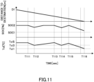
- FIG. 11 is a timing chart when the state of charge reducing control according to the present embodiment is executed.
- the EV mode is started at a timing T111 at which the vehicle can reach the destination in the EV mode, and when the engine coolant temperature Tcl reaches the third threshold value Tcl3 at a timing T 112, the engine 1 is operated under the normal control. Then, at a timing T115, when the controller 20 determines that the minimum engine coolant temperature Tclmin does not fall below the first threshold value Tcl1 even if the EV mode is executed until the vehicle reaches the destination, the EV mode is resumed, and the EV mode is continued until a timing T116 at which the vehicle reaches the destination.
- a section from the timing T112 to the timing T115 is repeated from the step S406 to the step S408 in FIG. 10 . That is, since the engine 1 is operated under the normal control, in parallel with the present control routine, control is executed to stop the engine 1 when the engine coolant temperature Tcl rises to the reference temperature TclS, and to operate the engine 1 when the engine coolant temperature Tcl drops to the third threshold value Tcl3.
- the engine coolant temperature Tcl can be maintained at the first threshold value Tcl1 or more until the vehicle reaches the destination while the SOC of the battery 6 is reduced. Furthermore, since there is a section in which the engine coolant temperature Tcl is maintained at the third threshold value Tcl3, performance degradation of a heating device and a defroster device due to a decrease in engine coolant temperature Tcl can be prevented. However, in the present embodiment, the SOC of the battery 6 increases in a section in which the engine 1 is operated under the normal control, and thus there is a possibility that SOC of the battery 6 at the time of reaching the destination is higher than that in the case of the third embodiment.
- the state of charge reducing control according to the present embodiment is executed in a case in which the driver selects the EV mode with the EV mode switch, a case in which the destination is set at which it is clear that the vehicle does not stay long enough for the engine 1 to be cold after reaching, or the like.
- the controller 20 continues the EV mode.
- the controller operates the engine 1 under the normal control that repeats the operation and the stop according to the SOC of the battery 6 and the engine coolant temperature Tcl while the traveling is continued by the traveling MG3, and resumes the EV mode when the vehicle reaches a position where the engine coolant temperature Tcl equal to or higher than the first threshold value Tcl1 can be maintained until the vehicle reaches the destination. Accordingly, the engine coolant temperature Tcl can be maintained at the first threshold value Tcl1 or more until the vehicle reaches the destination while the SOC of the battery 6 is reduced. Furthermore, since there is the section in which the engine coolant temperature Tcl is maintained at the third threshold value Tcl3, the performance degradation of the heating device and the defroster device due to the decrease in engine coolant temperature Tcl can be prevented.
Landscapes
- Engineering & Computer Science (AREA)
- Transportation (AREA)
- Mechanical Engineering (AREA)
- Automation & Control Theory (AREA)
- Chemical & Material Sciences (AREA)
- Combustion & Propulsion (AREA)
- Life Sciences & Earth Sciences (AREA)
- Sustainable Development (AREA)
- Sustainable Energy (AREA)
- Power Engineering (AREA)
- Mathematical Physics (AREA)
- Human Computer Interaction (AREA)
- Physics & Mathematics (AREA)
- Hybrid Electric Vehicles (AREA)
- Electric Propulsion And Braking For Vehicles (AREA)
Applications Claiming Priority (1)
| Application Number | Priority Date | Filing Date | Title |
|---|---|---|---|
| PCT/IB2021/000108 WO2022175702A1 (ja) | 2021-02-18 | 2021-02-18 | ハイブリッド車両制御方法及びハイブリッド車両制御装置 |
Publications (3)
| Publication Number | Publication Date |
|---|---|
| EP4296130A1 EP4296130A1 (en) | 2023-12-27 |
| EP4296130A4 EP4296130A4 (en) | 2024-03-06 |
| EP4296130B1 true EP4296130B1 (en) | 2024-11-20 |
Family
ID=82931431
Family Applications (1)
| Application Number | Title | Priority Date | Filing Date |
|---|---|---|---|
| EP21926061.9A Active EP4296130B1 (en) | 2021-02-18 | 2021-02-18 | Hybrid vehicle control method and hybrid vehicle control device |
Country Status (5)
| Country | Link |
|---|---|
| US (1) | US12024156B2 (https=) |
| EP (1) | EP4296130B1 (https=) |
| JP (1) | JP7459367B2 (https=) |
| CN (1) | CN116997493B (https=) |
| WO (1) | WO2022175702A1 (https=) |
Families Citing this family (3)
| Publication number | Priority date | Publication date | Assignee | Title |
|---|---|---|---|---|
| JPWO2024189720A1 (https=) * | 2023-03-13 | 2024-09-19 | ||
| KR20250000061A (ko) * | 2023-06-23 | 2025-01-02 | 현대자동차주식회사 | 전기자동차 및 그의 제어 방법 |
| KR102921244B1 (ko) * | 2024-01-10 | 2026-01-30 | 주식회사 현대케피코 | 하이브리드 차량의 배터리 충전 제어 방법 및 장치 |
Family Cites Families (36)
| Publication number | Priority date | Publication date | Assignee | Title |
|---|---|---|---|---|
| DE102004006991B4 (de) * | 2004-02-12 | 2014-01-30 | Volkswagen Ag | Verfahren zum Betreiben einer Brennkraftmaschine |
| JP5010378B2 (ja) * | 2007-07-24 | 2012-08-29 | トヨタ自動車株式会社 | ハイブリッド車両の制御装置 |
| JP5104708B2 (ja) * | 2008-10-10 | 2012-12-19 | トヨタ自動車株式会社 | ハイブリッド車両の制御装置および制御方法 |
| JP2011148439A (ja) * | 2010-01-22 | 2011-08-04 | Toyota Motor Corp | 車両の制御装置 |
| JP4962604B2 (ja) * | 2010-07-21 | 2012-06-27 | トヨタ自動車株式会社 | ハイブリッド車両の制御装置およびそれを備えるハイブリッド車両 |
| JP5899674B2 (ja) * | 2011-06-15 | 2016-04-06 | 日産自動車株式会社 | ハイブリッド車両の制御装置 |
| CN103796888B (zh) * | 2011-09-13 | 2016-04-20 | 丰田自动车株式会社 | 车辆的控制装置和控制方法 |
| JP5928497B2 (ja) | 2014-01-31 | 2016-06-01 | トヨタ自動車株式会社 | 車両 |
| JP2015147498A (ja) | 2014-02-06 | 2015-08-20 | 株式会社デンソー | 車両制御装置 |
| DE112015000200B4 (de) * | 2014-09-23 | 2022-03-24 | Hanon Systems | Verfahren für ein Klimaanlagensystem für Hybridfahrzeuge |
| JP6264258B2 (ja) * | 2014-10-23 | 2018-01-24 | 株式会社デンソー | 車両の制御装置 |
| KR101619653B1 (ko) * | 2014-12-03 | 2016-05-10 | 현대자동차주식회사 | 하이브리드 자동차의 난방시 엔진 아이들 운전 제어 방법 |
| JP6269539B2 (ja) * | 2015-03-09 | 2018-01-31 | トヨタ自動車株式会社 | ハイブリッド車両 |
| JP6323387B2 (ja) * | 2015-04-21 | 2018-05-16 | 株式会社デンソー | 走行制御装置 |
| JP2017081416A (ja) | 2015-10-28 | 2017-05-18 | トヨタ自動車株式会社 | 車両制御装置 |
| DE102015014875A1 (de) * | 2015-11-17 | 2016-08-04 | Daimler Ag | Verfahren zum Betrieb eines Hybridfahrzeuges |
| KR101776502B1 (ko) * | 2016-05-26 | 2017-09-07 | 현대자동차주식회사 | 차량의 난방 공조를 위한 엔진 제어 방법 |
| KR20180067260A (ko) * | 2016-12-12 | 2018-06-20 | 현대자동차주식회사 | 하이브리드 차량의 엔진 제어 장치 및 방법 |
| KR101923933B1 (ko) * | 2016-12-16 | 2018-11-30 | 현대자동차주식회사 | 하이브리드 자동차 및 그를 위한 주행 모드 제어 방법 |
| JP6583244B2 (ja) * | 2016-12-19 | 2019-10-02 | トヨタ自動車株式会社 | ハイブリッド車両の制御装置 |
| KR102295581B1 (ko) * | 2017-06-30 | 2021-08-30 | 현대자동차주식회사 | 하이브리드 자동차 및 그를 위한 공조 제어 방법 |
| KR102343955B1 (ko) * | 2017-07-31 | 2021-12-27 | 현대자동차주식회사 | 하이브리드 자동차 및 그를 위한 주행 모드 제어 방법 |
| KR102417897B1 (ko) * | 2017-09-07 | 2022-07-07 | 현대자동차주식회사 | 친환경 차량 충전 제어 장치, 그를 포함한 시스템 및 그 방법 |
| KR102355425B1 (ko) * | 2017-09-29 | 2022-01-26 | 현대자동차주식회사 | 하이브리드 자동차 및 그를 위한 엔진 제어 방법 |
| KR102444661B1 (ko) * | 2017-11-01 | 2022-09-19 | 현대자동차주식회사 | 하이브리드 자동차 및 그를 위한 주행 모드 제어 방법 |
| JP7003606B2 (ja) * | 2017-12-05 | 2022-01-20 | トヨタ自動車株式会社 | ハイブリッド自動車およびこれに搭載される制御装置 |
| JP6984372B2 (ja) * | 2017-12-07 | 2021-12-17 | トヨタ自動車株式会社 | ハイブリッド自動車 |
| US11117566B2 (en) * | 2018-05-08 | 2021-09-14 | Ford Global Technologies, Llc | Methods and systems of a hybrid vehicle |
| JP7103184B2 (ja) * | 2018-11-16 | 2022-07-20 | トヨタ自動車株式会社 | ハイブリッド車両の制御装置、ハイブリッド車両の制御方法、及びハイブリッド車両の制御プログラム |
| JP7119941B2 (ja) * | 2018-11-22 | 2022-08-17 | トヨタ自動車株式会社 | 車両の制御システム |
| JP7177485B2 (ja) * | 2019-03-15 | 2022-11-24 | 日立Astemo株式会社 | 制御装置 |
| KR20210077088A (ko) * | 2019-12-16 | 2021-06-25 | 현대자동차주식회사 | 하이브리드 자동차 및 그를 위한 엔진 기동 제어 방법 |
| JP7534097B2 (ja) * | 2020-02-13 | 2024-08-14 | 本田技研工業株式会社 | 制御装置及びプログラム |
| KR102873159B1 (ko) * | 2020-06-25 | 2025-10-16 | 현대자동차주식회사 | 하이브리드 자동차 및 그 제어 방법 |
| KR102923211B1 (ko) * | 2020-10-15 | 2026-02-04 | 현대자동차주식회사 | 하이브리드 차량의 난방 제어 방법 및 장치 |
| KR102886279B1 (ko) * | 2020-11-04 | 2025-11-13 | 현대자동차주식회사 | FATC 엔진 On 후 냉각을 고려한 엔진 On 라인의 가변 제어 시스템 |
-
2021
- 2021-02-18 WO PCT/IB2021/000108 patent/WO2022175702A1/ja not_active Ceased
- 2021-02-18 EP EP21926061.9A patent/EP4296130B1/en active Active
- 2021-02-18 JP JP2023500119A patent/JP7459367B2/ja active Active
- 2021-02-18 CN CN202180093905.6A patent/CN116997493B/zh active Active
- 2021-02-18 US US18/277,736 patent/US12024156B2/en active Active
Also Published As
| Publication number | Publication date |
|---|---|
| US20240092339A1 (en) | 2024-03-21 |
| JP7459367B2 (ja) | 2024-04-01 |
| EP4296130A4 (en) | 2024-03-06 |
| CN116997493B (zh) | 2024-10-08 |
| US12024156B2 (en) | 2024-07-02 |
| JPWO2022175702A1 (https=) | 2022-08-25 |
| EP4296130A1 (en) | 2023-12-27 |
| WO2022175702A1 (ja) | 2022-08-25 |
| CN116997493A (zh) | 2023-11-03 |
Similar Documents
| Publication | Publication Date | Title |
|---|---|---|
| US11345347B2 (en) | Brake control device for vehicle | |
| US10471950B2 (en) | Hybrid vehicle and method of changing operation mode for the same | |
| EP1136311A2 (en) | Electric energy charging control apparatus and method for hybrid vehicle | |
| EP4296130B1 (en) | Hybrid vehicle control method and hybrid vehicle control device | |
| US9796290B2 (en) | Method and apparatus of controlling output voltage of DC converter for vehicle including driving motor | |
| EP3647139B1 (en) | Travel assistance apparatus for hybrid vehicle | |
| EP2447518B1 (en) | Control apparatus for a vehicle having a prime mover | |
| JP5729484B2 (ja) | 走行環境予測装置および車両制御装置、並びにそれらの方法 | |
| EP3406498B1 (en) | Hybrid vehicle | |
| WO2013072974A1 (ja) | 車両制御装置、車両、および車両制御方法 | |
| US20210402976A1 (en) | Method of Controlling Generator for Vehicle | |
| CN114144345A (zh) | 改进车辆中的混合动力总成的燃料经济性的方法和系统 | |
| JP5201013B2 (ja) | 温度調整装置、温度調整方法および温度調整プログラム | |
| JP7594941B2 (ja) | ハイブリッド車両制御方法及びハイブリッド車両制御装置 | |
| US12617387B2 (en) | Method and system for improving fuel economy of a hybrid powertrain in a vehicle | |
| EP4378774A1 (en) | Method and device for regenerative control of hybrid vehicle | |
| WO2026053409A1 (ja) | 情報処理方法および情報処理装置 | |
| JP2024130339A (ja) | ハイブリッド車両制御方法及びハイブリッド車両制御装置 | |
| JP2025167986A (ja) | ハイブリッド車両の制御装置 | |
| WO2026053410A1 (ja) | 情報処理方法および情報処理装置 | |
| CN121043855A (zh) | 混合动力车 | |
| CN114655185A (zh) | 混合动力车辆的控制装置及混合动力车辆的控制方法 | |
| JP2020125001A (ja) | ハイブリッド車両の移動支援装置 |
Legal Events
| Date | Code | Title | Description |
|---|---|---|---|
| STAA | Information on the status of an ep patent application or granted ep patent |
Free format text: STATUS: THE INTERNATIONAL PUBLICATION HAS BEEN MADE |
|
| PUAI | Public reference made under article 153(3) epc to a published international application that has entered the european phase |
Free format text: ORIGINAL CODE: 0009012 |
|
| STAA | Information on the status of an ep patent application or granted ep patent |
Free format text: STATUS: REQUEST FOR EXAMINATION WAS MADE |
|
| 17P | Request for examination filed |
Effective date: 20230818 |
|
| AK | Designated contracting states |
Kind code of ref document: A1 Designated state(s): AL AT BE BG CH CY CZ DE DK EE ES FI FR GB GR HR HU IE IS IT LI LT LU LV MC MK MT NL NO PL PT RO RS SE SI SK SM TR |
|
| RAP1 | Party data changed (applicant data changed or rights of an application transferred) |
Owner name: NEW H POWERTRAIN HOLDING, S.L.U. Owner name: NISSAN MOTOR CO., LTD. |
|
| A4 | Supplementary search report drawn up and despatched |
Effective date: 20240201 |
|
| RIC1 | Information provided on ipc code assigned before grant |
Ipc: B60W 50/14 20200101ALI20240126BHEP Ipc: B60W 50/00 20060101ALI20240126BHEP Ipc: B60W 40/02 20060101ALI20240126BHEP Ipc: B60W 30/194 20120101ALI20240126BHEP Ipc: B60W 30/192 20120101ALI20240126BHEP Ipc: B60W 30/188 20120101ALI20240126BHEP Ipc: B60W 30/18 20120101ALI20240126BHEP Ipc: B60W 20/40 20160101ALI20240126BHEP Ipc: B60W 20/14 20160101ALI20240126BHEP Ipc: B60W 20/11 20160101ALI20240126BHEP Ipc: B60W 10/08 20060101ALI20240126BHEP Ipc: B60K 6/46 20071001ALI20240126BHEP Ipc: B60K 6/442 20071001ALI20240126BHEP Ipc: B60L 50/61 20190101ALI20240126BHEP Ipc: B60W 10/26 20060101ALI20240126BHEP Ipc: B60W 10/06 20060101ALI20240126BHEP Ipc: B60W 20/13 20160101ALI20240126BHEP Ipc: B60W 20/12 20160101AFI20240126BHEP |
|
| DAV | Request for validation of the european patent (deleted) | ||
| DAX | Request for extension of the european patent (deleted) | ||
| REG | Reference to a national code |
Ref country code: DE Ref legal event code: R079 Free format text: PREVIOUS MAIN CLASS: B60W0020120000 Ipc: B60K0006460000 Ref document number: 602021022244 Country of ref document: DE |
|
| GRAP | Despatch of communication of intention to grant a patent |
Free format text: ORIGINAL CODE: EPIDOSNIGR1 |
|
| STAA | Information on the status of an ep patent application or granted ep patent |
Free format text: STATUS: GRANT OF PATENT IS INTENDED |
|
| RIC1 | Information provided on ipc code assigned before grant |
Ipc: B60L 50/61 20190101ALI20240827BHEP Ipc: B60W 10/26 20060101ALI20240827BHEP Ipc: B60W 10/08 20060101ALI20240827BHEP Ipc: B60W 10/06 20060101ALI20240827BHEP Ipc: B60W 50/14 20200101ALI20240827BHEP Ipc: B60W 50/00 20060101ALI20240827BHEP Ipc: B60W 40/02 20060101ALI20240827BHEP Ipc: B60W 30/194 20120101ALI20240827BHEP Ipc: B60W 30/192 20120101ALI20240827BHEP Ipc: B60W 30/188 20120101ALI20240827BHEP Ipc: B60W 30/18 20120101ALI20240827BHEP Ipc: B60W 20/40 20160101ALI20240827BHEP Ipc: B60W 20/14 20160101ALI20240827BHEP Ipc: B60W 20/13 20160101ALI20240827BHEP Ipc: B60W 20/12 20160101ALI20240827BHEP Ipc: B60W 20/11 20160101ALI20240827BHEP Ipc: B60L 58/13 20190101ALI20240827BHEP Ipc: B60L 58/12 20190101ALI20240827BHEP Ipc: B60K 6/442 20071001ALI20240827BHEP Ipc: B60K 6/46 20071001AFI20240827BHEP |
|
| GRAS | Grant fee paid |
Free format text: ORIGINAL CODE: EPIDOSNIGR3 |
|
| INTG | Intention to grant announced |
Effective date: 20240916 |
|
| GRAA | (expected) grant |
Free format text: ORIGINAL CODE: 0009210 |
|
| STAA | Information on the status of an ep patent application or granted ep patent |
Free format text: STATUS: THE PATENT HAS BEEN GRANTED |
|
| AK | Designated contracting states |
Kind code of ref document: B1 Designated state(s): AL AT BE BG CH CY CZ DE DK EE ES FI FR GB GR HR HU IE IS IT LI LT LU LV MC MK MT NL NO PL PT RO RS SE SI SK SM TR |
|
| REG | Reference to a national code |
Ref country code: GB Ref legal event code: FG4D |
|
| REG | Reference to a national code |
Ref country code: CH Ref legal event code: EP |
|
| REG | Reference to a national code |
Ref country code: DE Ref legal event code: R096 Ref document number: 602021022244 Country of ref document: DE |
|
| REG | Reference to a national code |
Ref country code: IE Ref legal event code: FG4D |
|
| REG | Reference to a national code |
Ref country code: LT Ref legal event code: MG9D |
|
| REG | Reference to a national code |
Ref country code: NL Ref legal event code: MP Effective date: 20241120 |
|
| PG25 | Lapsed in a contracting state [announced via postgrant information from national office to epo] |
Ref country code: IS Free format text: LAPSE BECAUSE OF FAILURE TO SUBMIT A TRANSLATION OF THE DESCRIPTION OR TO PAY THE FEE WITHIN THE PRESCRIBED TIME-LIMIT Effective date: 20250320 Ref country code: HR Free format text: LAPSE BECAUSE OF FAILURE TO SUBMIT A TRANSLATION OF THE DESCRIPTION OR TO PAY THE FEE WITHIN THE PRESCRIBED TIME-LIMIT Effective date: 20241120 Ref country code: PT Free format text: LAPSE BECAUSE OF FAILURE TO SUBMIT A TRANSLATION OF THE DESCRIPTION OR TO PAY THE FEE WITHIN THE PRESCRIBED TIME-LIMIT Effective date: 20250320 |
|
| PG25 | Lapsed in a contracting state [announced via postgrant information from national office to epo] |
Ref country code: FI Free format text: LAPSE BECAUSE OF FAILURE TO SUBMIT A TRANSLATION OF THE DESCRIPTION OR TO PAY THE FEE WITHIN THE PRESCRIBED TIME-LIMIT Effective date: 20241120 Ref country code: NL Free format text: LAPSE BECAUSE OF FAILURE TO SUBMIT A TRANSLATION OF THE DESCRIPTION OR TO PAY THE FEE WITHIN THE PRESCRIBED TIME-LIMIT Effective date: 20241120 |
|
| REG | Reference to a national code |
Ref country code: AT Ref legal event code: MK05 Ref document number: 1743283 Country of ref document: AT Kind code of ref document: T Effective date: 20241120 |
|
| PG25 | Lapsed in a contracting state [announced via postgrant information from national office to epo] |
Ref country code: BG Free format text: LAPSE BECAUSE OF FAILURE TO SUBMIT A TRANSLATION OF THE DESCRIPTION OR TO PAY THE FEE WITHIN THE PRESCRIBED TIME-LIMIT Effective date: 20241120 |
|
| PG25 | Lapsed in a contracting state [announced via postgrant information from national office to epo] |
Ref country code: ES Free format text: LAPSE BECAUSE OF FAILURE TO SUBMIT A TRANSLATION OF THE DESCRIPTION OR TO PAY THE FEE WITHIN THE PRESCRIBED TIME-LIMIT Effective date: 20241120 |
|
| PG25 | Lapsed in a contracting state [announced via postgrant information from national office to epo] |
Ref country code: NO Free format text: LAPSE BECAUSE OF FAILURE TO SUBMIT A TRANSLATION OF THE DESCRIPTION OR TO PAY THE FEE WITHIN THE PRESCRIBED TIME-LIMIT Effective date: 20250220 |
|
| PG25 | Lapsed in a contracting state [announced via postgrant information from national office to epo] |
Ref country code: AT Free format text: LAPSE BECAUSE OF FAILURE TO SUBMIT A TRANSLATION OF THE DESCRIPTION OR TO PAY THE FEE WITHIN THE PRESCRIBED TIME-LIMIT Effective date: 20241120 Ref country code: GR Free format text: LAPSE BECAUSE OF FAILURE TO SUBMIT A TRANSLATION OF THE DESCRIPTION OR TO PAY THE FEE WITHIN THE PRESCRIBED TIME-LIMIT Effective date: 20250221 Ref country code: LV Free format text: LAPSE BECAUSE OF FAILURE TO SUBMIT A TRANSLATION OF THE DESCRIPTION OR TO PAY THE FEE WITHIN THE PRESCRIBED TIME-LIMIT Effective date: 20241120 |
|
| PG25 | Lapsed in a contracting state [announced via postgrant information from national office to epo] |
Ref country code: PL Free format text: LAPSE BECAUSE OF FAILURE TO SUBMIT A TRANSLATION OF THE DESCRIPTION OR TO PAY THE FEE WITHIN THE PRESCRIBED TIME-LIMIT Effective date: 20241120 |
|
| PG25 | Lapsed in a contracting state [announced via postgrant information from national office to epo] |
Ref country code: RS Free format text: LAPSE BECAUSE OF FAILURE TO SUBMIT A TRANSLATION OF THE DESCRIPTION OR TO PAY THE FEE WITHIN THE PRESCRIBED TIME-LIMIT Effective date: 20250220 |
|
| PG25 | Lapsed in a contracting state [announced via postgrant information from national office to epo] |
Ref country code: SM Free format text: LAPSE BECAUSE OF FAILURE TO SUBMIT A TRANSLATION OF THE DESCRIPTION OR TO PAY THE FEE WITHIN THE PRESCRIBED TIME-LIMIT Effective date: 20241120 |
|
| PG25 | Lapsed in a contracting state [announced via postgrant information from national office to epo] |
Ref country code: DK Free format text: LAPSE BECAUSE OF FAILURE TO SUBMIT A TRANSLATION OF THE DESCRIPTION OR TO PAY THE FEE WITHIN THE PRESCRIBED TIME-LIMIT Effective date: 20241120 |
|
| PG25 | Lapsed in a contracting state [announced via postgrant information from national office to epo] |
Ref country code: EE Free format text: LAPSE BECAUSE OF FAILURE TO SUBMIT A TRANSLATION OF THE DESCRIPTION OR TO PAY THE FEE WITHIN THE PRESCRIBED TIME-LIMIT Effective date: 20241120 |
|
| PG25 | Lapsed in a contracting state [announced via postgrant information from national office to epo] |
Ref country code: RO Free format text: LAPSE BECAUSE OF FAILURE TO SUBMIT A TRANSLATION OF THE DESCRIPTION OR TO PAY THE FEE WITHIN THE PRESCRIBED TIME-LIMIT Effective date: 20241120 |
|
| PG25 | Lapsed in a contracting state [announced via postgrant information from national office to epo] |
Ref country code: SK Free format text: LAPSE BECAUSE OF FAILURE TO SUBMIT A TRANSLATION OF THE DESCRIPTION OR TO PAY THE FEE WITHIN THE PRESCRIBED TIME-LIMIT Effective date: 20241120 |
|
| PG25 | Lapsed in a contracting state [announced via postgrant information from national office to epo] |
Ref country code: CZ Free format text: LAPSE BECAUSE OF FAILURE TO SUBMIT A TRANSLATION OF THE DESCRIPTION OR TO PAY THE FEE WITHIN THE PRESCRIBED TIME-LIMIT Effective date: 20241120 |
|
| PG25 | Lapsed in a contracting state [announced via postgrant information from national office to epo] |
Ref country code: IT Free format text: LAPSE BECAUSE OF FAILURE TO SUBMIT A TRANSLATION OF THE DESCRIPTION OR TO PAY THE FEE WITHIN THE PRESCRIBED TIME-LIMIT Effective date: 20241120 |
|
| REG | Reference to a national code |
Ref country code: DE Ref legal event code: R097 Ref document number: 602021022244 Country of ref document: DE |
|
| PG25 | Lapsed in a contracting state [announced via postgrant information from national office to epo] |
Ref country code: SE Free format text: LAPSE BECAUSE OF FAILURE TO SUBMIT A TRANSLATION OF THE DESCRIPTION OR TO PAY THE FEE WITHIN THE PRESCRIBED TIME-LIMIT Effective date: 20241120 |
|
| PG25 | Lapsed in a contracting state [announced via postgrant information from national office to epo] |
Ref country code: MC Free format text: LAPSE BECAUSE OF FAILURE TO SUBMIT A TRANSLATION OF THE DESCRIPTION OR TO PAY THE FEE WITHIN THE PRESCRIBED TIME-LIMIT Effective date: 20241120 |
|
| PLBE | No opposition filed within time limit |
Free format text: ORIGINAL CODE: 0009261 |
|
| STAA | Information on the status of an ep patent application or granted ep patent |
Free format text: STATUS: NO OPPOSITION FILED WITHIN TIME LIMIT |
|
| REG | Reference to a national code |
Ref country code: CH Ref legal event code: PL |
|
| PG25 | Lapsed in a contracting state [announced via postgrant information from national office to epo] |
Ref country code: LU Free format text: LAPSE BECAUSE OF NON-PAYMENT OF DUE FEES Effective date: 20250218 |
|
| PG25 | Lapsed in a contracting state [announced via postgrant information from national office to epo] |
Ref country code: CH Free format text: LAPSE BECAUSE OF NON-PAYMENT OF DUE FEES Effective date: 20250228 |
|
| 26N | No opposition filed |
Effective date: 20250821 |
|
| REG | Reference to a national code |
Ref country code: BE Ref legal event code: MM Effective date: 20250228 |
|
| PG25 | Lapsed in a contracting state [announced via postgrant information from national office to epo] |
Ref country code: BE Free format text: LAPSE BECAUSE OF NON-PAYMENT OF DUE FEES Effective date: 20250228 |
|
| PG25 | Lapsed in a contracting state [announced via postgrant information from national office to epo] |
Ref country code: IE Free format text: LAPSE BECAUSE OF NON-PAYMENT OF DUE FEES Effective date: 20250218 |
|
| PGFP | Annual fee paid to national office [announced via postgrant information from national office to epo] |
Ref country code: GB Payment date: 20260121 Year of fee payment: 6 |
|
| PGFP | Annual fee paid to national office [announced via postgrant information from national office to epo] |
Ref country code: DE Payment date: 20260121 Year of fee payment: 6 |
|
| PGFP | Annual fee paid to national office [announced via postgrant information from national office to epo] |
Ref country code: FR Payment date: 20260121 Year of fee payment: 6 |