EP4288656B1 - Hydraulische maschine vom typ pelton - Google Patents
Hydraulische maschine vom typ pelton Download PDFInfo
- Publication number
- EP4288656B1 EP4288656B1 EP21839849.3A EP21839849A EP4288656B1 EP 4288656 B1 EP4288656 B1 EP 4288656B1 EP 21839849 A EP21839849 A EP 21839849A EP 4288656 B1 EP4288656 B1 EP 4288656B1
- Authority
- EP
- European Patent Office
- Prior art keywords
- deflector
- guide wall
- holm
- hydraulic machine
- roof
- Prior art date
- Legal status (The legal status is an assumption and is not a legal conclusion. Google has not performed a legal analysis and makes no representation as to the accuracy of the status listed.)
- Active
Links
Images


Classifications
-
- F—MECHANICAL ENGINEERING; LIGHTING; HEATING; WEAPONS; BLASTING
- F03—MACHINES OR ENGINES FOR LIQUIDS; WIND, SPRING, OR WEIGHT MOTORS; PRODUCING MECHANICAL POWER OR A REACTIVE PROPULSIVE THRUST, NOT OTHERWISE PROVIDED FOR
- F03B—MACHINES OR ENGINES FOR LIQUIDS
- F03B1/00—Engines of impulse type, i.e. turbines with jets of high-velocity liquid impinging on blades or like rotors, e.g. Pelton wheels; Parts or details peculiar thereto
- F03B1/04—Nozzles; Nozzle-carrying members
-
- F—MECHANICAL ENGINEERING; LIGHTING; HEATING; WEAPONS; BLASTING
- F03—MACHINES OR ENGINES FOR LIQUIDS; WIND, SPRING, OR WEIGHT MOTORS; PRODUCING MECHANICAL POWER OR A REACTIVE PROPULSIVE THRUST, NOT OTHERWISE PROVIDED FOR
- F03B—MACHINES OR ENGINES FOR LIQUIDS
- F03B15/00—Controlling
- F03B15/02—Controlling by varying liquid flow
- F03B15/20—Controlling by varying liquid flow specially adapted for turbines with jets of high-velocity liquid impinging on bladed or like rotors
-
- F—MECHANICAL ENGINEERING; LIGHTING; HEATING; WEAPONS; BLASTING
- F05—INDEXING SCHEMES RELATING TO ENGINES OR PUMPS IN VARIOUS SUBCLASSES OF CLASSES F01-F04
- F05B—INDEXING SCHEME RELATING TO WIND, SPRING, WEIGHT, INERTIA OR LIKE MOTORS, TO MACHINES OR ENGINES FOR LIQUIDS COVERED BY SUBCLASSES F03B, F03D AND F03G
- F05B2240/00—Components
- F05B2240/10—Stators
- F05B2240/12—Fluid guiding means, e.g. vanes
-
- Y—GENERAL TAGGING OF NEW TECHNOLOGICAL DEVELOPMENTS; GENERAL TAGGING OF CROSS-SECTIONAL TECHNOLOGIES SPANNING OVER SEVERAL SECTIONS OF THE IPC; TECHNICAL SUBJECTS COVERED BY FORMER USPC CROSS-REFERENCE ART COLLECTIONS [XRACs] AND DIGESTS
- Y02—TECHNOLOGIES OR APPLICATIONS FOR MITIGATION OR ADAPTATION AGAINST CLIMATE CHANGE
- Y02E—REDUCTION OF GREENHOUSE GAS [GHG] EMISSIONS, RELATED TO ENERGY GENERATION, TRANSMISSION OR DISTRIBUTION
- Y02E10/00—Energy generation through renewable energy sources
- Y02E10/20—Hydro energy
Definitions
- the invention relates to a hydraulic machine of the Pelton type with an impeller, at least two nozzles and a guide wall surrounding the impeller for diverting spray water, wherein the nozzles are guided through the guide wall so that their mouths are located on the inner surface of the guide wall which is in contact with the spray water.
- a generic hydraulic machine is used in the EN 1 02010 024 475 A1 Similar hydraulic machines are disclosed in the documents JP-S60-30477-A and GB 140 828 A disclosed.
- the object of the invention is to provide a hydraulic machine of the Pelton type with a guide wall, the machine comprising deflectors.
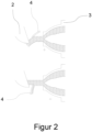
- FIG 2 shows in a highly schematic representation the two possible operating principles of deflectors in hydraulic machines of the Pelton type.
- a deflector comprises a deflection body which is designed to interact with the water jet.
- the deflectors are marked with 4.
- the deflectors When the deflectors are activated, the deflectors perform a rotary movement.
- the axes of rotation of this movement are in Figure 2 indicated by the small crosses.
- the axes of rotation are arranged on the side of the nozzles 3 facing away from the impeller.
- One such deflector is provided for each nozzle.
- the first operating principle in which the deflector 4 approaches the water jet from the side facing the impeller. When the deflector 4 penetrates the water jet, it is deflected outwards so that the water jet only partially hits the cups 2. When the deflector is fully activated, the deflector 4 is arranged in such a way that the water jet is deflected past the cups in its entirety so that no energy can be transferred from the water jet to the impeller 1.
- a deflector designed according to this operating principle is also referred to as a pusher because it pushes the water jet outwards.
- the second operating principle in which the deflector 4 approaches the water jet from the side facing away from the impeller.
- the deflector 4 penetrates the water jet, part of the water jet is deflected outwards so that the deflected part of the water jet does not hit the cups 2.
- the deflector is fully activated, the deflector 4 is arranged so that the water jet is deflected past the cups in its entirety so that no energy can be transferred from the water jet to the impeller 1.
- a deflector designed according to this operating principle is also referred to as a cutter because it cuts off part of the water jet and deflects it outwards.
- a hydraulic machine constructed in accordance with the present invention may comprise deflectors in accordance with both of the described operating principles.
- Figure 3 shows a schematic representation of a deflector according to the state of the art.
- the upper part of Figure 3 the deflector in the direction of view along the axis of rotation of the deflector, which is again indicated by a small cross.
- the lower part of Figure 3 shows the deflector in a direction perpendicular to the axis of rotation of the deflector, which is indicated by the dashed line.
- the deflector forms a rocker or a lever, which can be rotated around the axis of rotation
- the deflector has the shape of a two-pronged fork, ie it comprises a beam-like section, in short a beam, which represents the stem of the fork and is connected to the two legs of the fork at the branching point of the fork.
- the beam is designated with 6 and one of the legs with 7.
- the deflection body 4 extends between the two ends of the legs 7 facing away from the beam 6.
- an engagement point which is designated with 8.
- the engagement point 8 is intended so that a servo motor can engage it in order to actuate the deflector.
- the axis of rotation of the deflector is arranged in such a way that it penetrates the deflector in the area of the legs 7.
- Figure 4 shows a deflector according to the present invention.
- the beam 6 is longer and the legs 7 are shorter, so that the axis of rotation of the deflector is arranged such that it penetrates the deflector in the area of the beam 6.
- Figure 5 shows a deflector according to the present invention in a further embodiment.
- the beam 6 includes a specially profiled section, which is marked with 9.
- the part of Figure 5 shows a section through the profiled spar section, with the letters AA indicating the position of the relevant section.
- the profile is roof-like.
- Figure 6 shows such a deflector in the installed position.
- This is an example of a deflector of the pusher type, which is shown in the deactivated position, ie in this position the water jet penetrates the deflector between the two legs of the forked section without touching the deflector body.
- the deflector could also be designed as a cutter.
- the support for the deflector is formed by a double tab, which is connected to the side of the nozzle facing away from the impeller and in Figure 6 is designated 10.
- the axis of rotation of the deflector is arranged outside the guide wall 5.
- the guide wall 5 is indicated by the dashed line.
- the inventive design of the deflector with a long beam and shortened fork means that the forked section including the deflector body is located completely within the guide wall 5 in every intended rotational position of the deflector.
- the deflector is guided through the guide wall 5 with only the beam, which means that the corresponding openings in the guide wall 5 can be kept small.
- the embodiment according to Figure 5 ie with profiled section 9, also has the advantage that the profiled beam section 9 is connected to the guide wall 5, which is also designed like a roof, so that this is continued by the profiled beam section 9.
- the spray-water-draining effect of the guide wall 5 is thus only minimally affected by the deflector.
Landscapes
- Engineering & Computer Science (AREA)
- Chemical & Material Sciences (AREA)
- Combustion & Propulsion (AREA)
- Mechanical Engineering (AREA)
- General Engineering & Computer Science (AREA)
- Hydraulic Turbines (AREA)
Description
- Die Erfindung betrifft eine hydraulische Maschine vom Typ Pelton mit einem Laufrad, wenigstens zwei Düsen und einer das Laufrad umgebenden Leitwand zum Ableiten von Spritzwasser, wobei die Düsen durch die Leitwand hindurchgeführt sind, so dass sich ihre Mündungen an der inneren, spritzwasserberührten Fläche der Leitwand befinden.
- Eine gattungsgemäße hydraulische Maschine wird in der
DE 1 02010 024 475 A1 offenbart. Ähnliche hydraulische Maschinen werden in den DokumentenJP S60 30477 A GB 140 828 A - Die Aufgabe der Erfindung ist es, eine hydraulische Maschine vom Typ Pelton mit einer Leitwand anzugeben, wobei die Maschine Ablenker umfasst.
- Die
DE 397389 offenbart den üblichen Aufbau eines solchen Ablenkers, welcher dazu dient den aus den Düsen austretenden Wasserstrahl so abzulenken, dass derselbe nicht mehr oder nur noch teilweise auf die Becher des Laufrades auftrifft. Dadurch kann die hydraulische Maschine schnell herunter geregelt werden, ohne dass ein Druckstoß zu befürchten ist. Außerdem ergibt sich durch das Zusammenwirken von Ablenker und Düsennadel eine doppelte Regulierbarkeit der hydraulischen Maschine. - Die Aufgabe wird erfindungsgemäß durch eine Ausführung entsprechend dem unabhängigen Anspruch gelöst. Weitere vorteilhafte Ausführungsformen der vorliegenden Erfindung finden sich in den Unteransprüchen.
- Im Folgenden wird die Erfindung anhand von Figuren erläutert. Die Figuren zeigen im Einzelnen:
- Fig.1
- Hydraulische Maschine vom Typ Pelton
- Fig.2
- Wirkprinzipien von Ablenkern
- Fig. 3
- Ablenker gemäß dem Stand der Technik
- Fig. 4
- Erfindungsgemäßer Ablenker in einer ersten Ausführungsform
- Fig. 5
- Erfindungsgemäßer Ablenker in einer zweiten Ausführungsform
- Fig. 6
- Erfindungsgemäßer Ablenker in Einbaulage
-
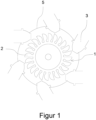
Figur 1 zeigt eine hydraulische Maschine vom Typ Pelton. Die hydraulische Maschine umfasst ein Laufrad, welches mit 1 bezeichnet ist. Das Laufrad 1 umfasst eine Vielzahl von Bechern, von denen einer mit 2 bezeichnet ist. Die hydraulische Maschine umfasst ferner wenigstens zwei Düsen, von denen eine mit 3 bezeichnet ist. Die inFigur 1 dargestellte hydraulische Maschine umfasst sechs Düsen 3. Die hydraulische Maschine umfasst außerdem eine Leitwand, welche mit 5 bezeichnet ist. Die Leitwand 5 dient der Ableitung von Spritzwasser und umschließt das Laufrad 1. Dazu kann die Leitwand 5, wie inFigur 1 dargestellt, ringförmig ausgebildet sein. Genauso gut könnte die Leitwand 5 aus mehreren Segmenten zusammengesetzt sein. Die einzelnen Segmente könnten eine gebogene Kontur oder eine geradlinige Kontur aufweisen. Auch Kombinationen hieraus sind möglich. Die Düsen 3 ragen von außen in den von der Leitwand 5 umschlossenen Raum hinein, so dass der während dem Betrieb der hydraulischen Maschine aus den Düsen 3 austretende Wasserstrahl sich beim Austreten aus den Düsen 3 im Inneren der Leitwand 5 befindet. Dazu weist die Leitwand 5 entsprechende Öffnungen auf. Die Leitwand 5 hat ein dachartiges Profil. Die entsprechende Linie inFigur 5 stellt dabei die Firstlinie der Leitwand 5 dar. Die Flächen der Leitwand 5 weichen sowohl in Blickrichtung als auch in der Gegenrichtung nach radial außen hin zurück. Spritzwasser wird auf diese Weise durch die Leitwand 5 vom Laufrad 1 weg nach außen abgeführt. -
Figur 2 zeigt in stark schematischer Darstellung die beiden möglichen Wirkprinzipien von Ablenkern in hydraulischen Maschinen vom Typ Pelton. Ein solcher Ablenker umfasst einen Ablenkkörper, welcher dazu vorgesehen ist, mit dem Wasserstrahl zu interagieren. InFigur 2 sind die Ablenkkörper mit 4 bezeichnet. Wenn die Ablenker aktiviert werden, führen die Ablenkkörper eine Drehbewegung aus. Die Drehachsen dieser Bewegung sind inFigur 2 durch die kleinen Kreuze angedeutet. Die Drehachsen sind jeweils auf der dem Laufrad abgewandten Seite der Düsen 3 angeordnet. Für jede Düse ist ein solcher Ablenker vorgesehen. - Im oberen Teil der
Figur 2 ist das erste Wirkprinzip dargestellt, bei dem sich der Ablenkkörper 4 von der zum Laufrad hin orientieren Seite des Wasserstrahls aus demselben nähert. Beim Eindringen des Ablenkkörpers 4 in den Wasserstrahl wird derselbe nach außen hin abgelenkt, so dass der Wasserstrahl nur noch teilweise auf die Becher 2 auftrifft. Bei vollständiger Aktivierung des Ablenkers ist der Ablenkkörper 4 so angeordnet, dass der Wasserstrahl im ganzem Umfang an den Bechern vorbeigelenkt wird, so dass keine Energie vom Wasserstrahl auf das Laufrad 1 übertragen werden kann. Ein Ablenker, welcher gemäß diesem Wirkprinzip ausgelegt ist, wird auch als Abdrücker bezeichnet, weil er den Wasserstrahl nach außen hin weg drückt. - Im unteren Teil der
Figur 2 ist das zweite Wirkprinzip dargestellt, bei dem sich der Ablenkkörper 4 von der dem Laufrad abgewandten Seite des Wasserstrahls aus demselben annähert. Beim Eindringen des Ablenkkörpers 4 in den Wasserstrahl wird ein Teil des Wasserstrahls nach außen hin abgelenkt, so dass der abgelenkte Teil des Wasserstrahls nicht auf die Becher 2 auftrifft. Bei vollständiger Aktivierung des Ablenkers ist der Ablenkkörper 4 so angeordnet, dass der Wasserstrahl im ganzem Umfang an den Bechern vorbeigelenkt wird, so dass keine Energie vom Wasserstrahl auf das Laufrad 1 übertragen werden kann. Ein Ablenker, welcher gemäß diesem Wirkprinzip ausgelegt ist, wird auch als Abschneider bezeichnet, weil er einen Teil des Wasserstrahls abschneidet und nach außen hin ablenkt. - Eine gemäß der vorliegenden Erfindung ausgeführte hydraulische Maschine kann Ablenker gemäß beiden der beschriebenen Wirkprinzipien umfassen.
-
Figur 3 zeigt in schematischer Darstellung einen Ablenker gemäß dem Stand der Technik. Dabei zeigt der obere Teil vonFigur 3 den Ablenker in Blickrichtung entlang der Drehachse des Ablenkers, welche wiederum durch ein kleines Kreuz angedeutet ist. Der untere Teil vonFigur 3 zeigt den Ablenker in einer Blickrichtung senkrecht zur Drehachse des Ablenkers welche durch die gestrichelte Linie angedeutet ist. Der Ablenker bildet eine Wippe bzw. einen Hebel, welcher um die Drehachse gedreht werden kann. Der Ablenker hat die Form einer zweizinkigen Gabel, d.h. er umfasst ein holmartiges Teilstück, kurz einen Holm, welcher den Stiel der Gabel darstellt und am Verzweigungspunkt der Gabel mit den beiden Schenkeln der Gabel verbunden ist. InFigur 3 ist der Holm mit 6 und einer der Schenkel mit 7 bezeichnet. Der Ablenkkörper 4 erstreckt sich zwischen den beiden dem Holm 6 abgewandten Enden der Schenkel 7. Am den Schenkeln 7 abgewandten Ende des Holms 6 ist eine Angriffspunkt angeordnet, welcher mit 8 bezeichnet ist. Der Angriffspunkt 8 ist dazu vorgesehen, dass an demselben ein Servomotor angreifen kann, um den Ablenker zu betätigen. Die Drehachse des Ablenkers ist so angeordnet, dass sie den Ablenker im Bereich der Schenkel 7 durchdringt. -
Figur 4 zeigt einen Ablenker gemäß der vorliegenden Erfindung. Im Unterschied zuFigur 3 ist der Holm 6 länger und die Schenkel 7 kürzer ausgeführt, so dass die Drehachse des Ablenkers so angeordnet ist, dass sie den Ablenker im Bereich des Holms 6 durchdringt. -
Figur 5 zeigt einen Ablenker gemäß der vorliegenden Erfindung in einer weiteren Ausführungsform. Im Unterschied zuFigur 4 umfasst der Holm 6 ein speziell profiliertes Teilstück, welches mit 9 bezeichnet ist. Der mit dem Pfeil markierte Teil vonFigur 5 zeigt einen Schnitt durch den profilierten Holmabschnitt, wobei die Buchstaben A-A die Lage des betreffenden Ausschnitts verdeutlichen. Das Profil ist dachartig ausgebildet. - Im Folgenden werden die Vorteile der in den
Figuren 4 und5 dargestellten Ausprägungen der erfindungsgemäßen Ablenker mit Hilfe vonFigur 6 erläutert.Figur 6 zeigt einen solchen Ablenker in Einbaulage. Es handelt sich beispielhaft um einen Ablenker vom Typ Abdrücker, welcher in deaktivierter Stellung dargestellt ist, d.h. in dieser Stellung durchdringt der Wasserstrahl den Ablenker zwischen den beiden Schenkeln des gegabelten Teilstücks hindurch, ohne dabei den Ablenkkörper zu berühren. Der Ablenker könnte auch als Abschneider ausgeführt sein. Das Auflager für den Ablenker wird durch eine Doppellasche gebildet, welche mit der dem Laufrad abgewandten Seite der Düse verbunden und inFigur 6 mit 10 bezeichnet ist. Die Drehachse des Ablenkers ist außerhalb der Leitwand 5 angeordnet. Die Leitwand 5 wird durch die gestrichelte Linie angedeutet. Die erfindungsgemäße Ausführung des Ablenkers mit langem Holm und verkürzter Gabel führt dazu, dass sich das gegabelte Teilstück samt Ablenkkörper in jeder vorgesehen Drehstellung des Ablenkers komplett innerhalb der Leitwand 5 befindet. Der Ablenker wird nur mit dem Holm durch die Leitwand 5 geführt, was bewirkt, dass die entsprechenden Öffnungen in der Leitwand 5 klein gehalten werden können. Die Ausführungsform gemäßFigur 5 , d.h. mit profiliertem Teilstück 9, hat zudem den Vorteil, dass sich der profilierte Holmabschnitt 9 an die ebenfalls dachartig ausgebildete Leitwand 5 anschließt, so dass diese durch den profilierten Holmabschnitt 9 weiter geführt wird. Die spritzwasserableitende Wirkung der Leitwand 5 wird so durch den Ablenker nur minimal beeinträchtigt. Die inFigur 5 oben und inFigur 6 sichtbare Rundung des Ablenkers im Bereich des profilierten Holmabschnittes 9 bewirkt, dass sich der Ablenker auch, wenn er etwas um die Drehachse gedreht wird, noch immer wie beschrieben mit dem profilierten Holmabschnitt 9 an die Leitwand 5 anschließt, da die Rundung einen Kreisbogen mit einem Mittelpunkt bildet, welcher mit der Drehachse des Ablenkers zusammenfällt. -
- 1
- Laufrad
- 2
- Becher
- 3
- Düse
- 4
- Ablenkkörper
- 5
- Leitwand
- 6
- Holm
- 7
- Schenkel
- 8
- Angriffspunkt
- 9
- Profilierter Holmabschnitt
- 10
- Lasche
Claims (3)
- Hydraulische Maschine vom Typ Pelton umfassend ein Laufrad (1) mit einer Vielzahl von Bechern (2), wenigstens zwei Düsen (3) und eine Leitwand (5) zur Ableitung von Spritzwasser, welche das Laufrad (1) umschließt, und wobei die Düsen (3) von außen in den von der Leitwand (5) umschlossenen Raum hineinragen, und wobei die hydraulische Maschine für jede Düse (3) einen Ablenker umfasst, welche die im Betrieb aus den Düsen austretenden Wasserstrahlen ablenken können, und wobei jeder Ablenker einen Holm (6), zwei Schenkel (7) und einen Ablenkkörper (4) umfasst, und wobei die zwei Schenkel (7) eine Gabel mit einem Verzweigungspunkt bilden, und der Holm (6) mit dem Verzweigungspunkt der Gabel verbunden ist, und wobei sich der Ablenkkörper (4) zwischen den beiden dem Holm (6) abgewandten Enden der Schenkeln (7) erstreckt, und wobei jeder Ablenker um eine Drehachse drehbar gelagert ausgeführt ist, und wobei die Drehachse den Ablenker im Bereich des Holms (6) durchdringt, und in jeder vorgesehen Drehstellung des Ablenkers die Gabel und der Ablenkkörper (4) komplett innerhalb der Leitwand (5) angeordnet sind, und wobei der Holm (6) die Leitwand (5) durchdringt.
- Hydraulische Maschine vom Typ Pelton nach Anspruch 1, wobei die Leitwand (5) ein dachartiges Profil aufweist, und der Holm (6) einen dachartig profilierten Abschnitt (9) umfasst, welcher so angeordnet ist, dass der dachartig profilierte Holmabschnitt (9) sich wenigstens in einer Drehstellung des Ablenkers an das dachartige Profil der Leitwand (5) anschließt.
- Hydraulische Maschine vom Typ Pelton nach Anspruch 2, wobei der profilierte Holmabschnitt (9) eine Kontur in Form eines Kreisbogens aufweist, wobei der Mittelpunkt des Kreisbogens mit der Drehachse des Ablenkers zusammenfällt, so dass der dachartig profilierte Holmabschnitt (9) sich in mehr als einer Drehstellung des Ablenkers an das dachartige Profil der Leitwand (5) anschließt.
Applications Claiming Priority (2)
| Application Number | Priority Date | Filing Date | Title |
|---|---|---|---|
| DE102021102464.1A DE102021102464B3 (de) | 2021-02-03 | 2021-02-03 | Hydraulische Maschine vom Typ Pelton |
| PCT/EP2021/085642 WO2022167130A1 (de) | 2021-02-03 | 2021-12-14 | Hydraulische maschine vom typ pelton |
Publications (2)
| Publication Number | Publication Date |
|---|---|
| EP4288656A1 EP4288656A1 (de) | 2023-12-13 |
| EP4288656B1 true EP4288656B1 (de) | 2024-07-24 |
Family
ID=79287843
Family Applications (1)
| Application Number | Title | Priority Date | Filing Date |
|---|---|---|---|
| EP21839849.3A Active EP4288656B1 (de) | 2021-02-03 | 2021-12-14 | Hydraulische maschine vom typ pelton |
Country Status (7)
| Country | Link |
|---|---|
| EP (1) | EP4288656B1 (de) |
| CN (1) | CN116829827B (de) |
| CL (1) | CL2023002286A1 (de) |
| CO (1) | CO2023010257A2 (de) |
| DE (1) | DE102021102464B3 (de) |
| PE (1) | PE20231396A1 (de) |
| WO (1) | WO2022167130A1 (de) |
Families Citing this family (1)
| Publication number | Priority date | Publication date | Assignee | Title |
|---|---|---|---|---|
| DE102022106296A1 (de) | 2022-03-17 | 2023-09-21 | Erlach & Erlach Gmbh | Peltonturbine |
Family Cites Families (14)
| Publication number | Priority date | Publication date | Assignee | Title |
|---|---|---|---|---|
| GB140828A (en) * | 1918-08-03 | 1921-08-29 | Anonima Officine Elettro Mecca | Improvements in or relating to means for regulating hydraulic turbines |
| DE397389C (de) | 1921-09-28 | 1924-06-20 | Charmilles Sa Ateliers | Doppelt wirkende Regelungsvorrichtung fuer Wasserturbinen |
| US2635847A (en) | 1947-05-31 | 1953-04-21 | Pelton Water Wheel Co | Turbine jet controller |
| DE1205019B (de) * | 1962-02-16 | 1965-11-11 | Voith Gmbh J M | Strahlablenker fuer mehrduesige vertikalachsige Freistrahlwasserturbinen |
| JPS6030477A (ja) * | 1983-07-08 | 1985-02-16 | Fuji Electric Co Ltd | ペルトン水車の鉄管の抜水装置 |
| JPS60187773A (ja) * | 1984-03-07 | 1985-09-25 | Fuji Electric Co Ltd | ペルトン水車の分岐管 |
| JPS63112276U (de) * | 1987-01-16 | 1988-07-19 | ||
| JPH071031B2 (ja) * | 1987-06-11 | 1995-01-11 | 富士電機株式会社 | ペルトン水車のデフレクタ駆動装置 |
| JP3601084B2 (ja) * | 1994-10-26 | 2004-12-15 | 富士電機システムズ株式会社 | ペルトン水車 |
| CN2228555Y (zh) * | 1995-08-14 | 1996-06-05 | 吴铁民 | 冲击式水轮机的喷嘴及其控制机构 |
| DE102010024475A1 (de) | 2010-06-21 | 2011-12-22 | Voith Patent Gmbh | Peltonturbine mit einem Wasserabfuhrsystem |
| CN104295435B (zh) | 2014-09-16 | 2016-05-25 | 哈尔滨电机厂有限责任公司 | 降低冲击式水轮机安全保护机构接力器操作容量的方法 |
| CN104265558A (zh) * | 2014-09-16 | 2015-01-07 | 哈尔滨电机厂有限责任公司 | 一种降低冲击式水轮机外调节机构接力器操作容量的方法 |
| JP6900612B2 (ja) * | 2017-06-23 | 2021-07-07 | 株式会社東芝 | ペルトン水車発電機 |
-
2021
- 2021-02-03 DE DE102021102464.1A patent/DE102021102464B3/de active Active
- 2021-12-14 WO PCT/EP2021/085642 patent/WO2022167130A1/de not_active Ceased
- 2021-12-14 PE PE2023002242A patent/PE20231396A1/es unknown
- 2021-12-14 EP EP21839849.3A patent/EP4288656B1/de active Active
- 2021-12-14 CN CN202180092468.6A patent/CN116829827B/zh active Active
-
2023
- 2023-08-01 CO CONC2023/0010257A patent/CO2023010257A2/es unknown
- 2023-08-02 CL CL2023002286A patent/CL2023002286A1/es unknown
Also Published As
| Publication number | Publication date |
|---|---|
| CN116829827A (zh) | 2023-09-29 |
| CL2023002286A1 (es) | 2024-01-12 |
| WO2022167130A1 (de) | 2022-08-11 |
| PE20231396A1 (es) | 2023-09-12 |
| CO2023010257A2 (es) | 2023-09-08 |
| DE102021102464B3 (de) | 2022-03-17 |
| CN116829827B (zh) | 2025-12-16 |
| EP4288656A1 (de) | 2023-12-13 |
Similar Documents
| Publication | Publication Date | Title |
|---|---|---|
| DE4008171C2 (de) | Vorrichtung zur Kühlung und Spülung des ringförmigen Sägeblattes einer Kreissäge ohne Zentrumsachse | |
| DE19510397A1 (de) | Gebläseeinheit | |
| EP2582963B1 (de) | Peltonturbine mit einem wasserabfuhrsystem | |
| EP0090090B1 (de) | Verfahren zum Reinigen von Hohlräumen in Doppelsitzventilen | |
| EP4288656B1 (de) | Hydraulische maschine vom typ pelton | |
| DE2631752B2 (de) | Schwenkende Berieselungsvorrichtung Ets. Carpano & Pons, Cluses, Haute-Savoie (Frankreich) | |
| WO2015051957A1 (de) | Turbinenschaufel sowie gasturbine | |
| DE3929561C1 (en) | Cleaning and spraying device for sieves in paper machines - has double wall tube with water inlet and hand-wheel operated dirt discharge | |
| EP3802383B1 (de) | Weichenvorrichtung | |
| DE3802360A1 (de) | Scheibenwischer | |
| EP3440340B1 (de) | Ringgatter für eine hydraulische maschine und verfahren zum schliessen | |
| DE69027178T2 (de) | Rundstrickmaschine mit Vorrichtung zur Wiederholung der Nadelauswahl an mindestens einer Fadenlieferungsstelle | |
| DE2602328C3 (de) | Drosselventil | |
| DE19909024C2 (de) | Messerscheibe einer Scheibenrad-Zerspanungsmaschine | |
| DE102020105504A1 (de) | Mausvorrichtung und Scrollradmodul | |
| DE262821C (de) | ||
| EP4556129A1 (de) | Sprühvorrichtung | |
| DE189025C (de) | ||
| DE3507921C1 (de) | Lenkstockschalter zur Fahrtrichtungsanzeige an Kraftfahrzeugen | |
| WO2009033526A1 (de) | Hybridpumpe zum fördern eines flüssigen pumpmediums | |
| DE319554C (de) | Freistrahlturbine nach Peltonraederart | |
| EP4378296A1 (de) | Mähmesservorrichtung | |
| EP4422809A1 (de) | Behälterreinigungsmaschine | |
| DE940253C (de) | Breitdreschmaschine mit Strohschneidvorrichtung | |
| DE3036543A1 (de) | Ventilsteuerung mit untenliegender nockenwelle und haengendem ventil |
Legal Events
| Date | Code | Title | Description |
|---|---|---|---|
| STAA | Information on the status of an ep patent application or granted ep patent |
Free format text: STATUS: UNKNOWN |
|
| STAA | Information on the status of an ep patent application or granted ep patent |
Free format text: STATUS: THE INTERNATIONAL PUBLICATION HAS BEEN MADE |
|
| PUAI | Public reference made under article 153(3) epc to a published international application that has entered the european phase |
Free format text: ORIGINAL CODE: 0009012 |
|
| STAA | Information on the status of an ep patent application or granted ep patent |
Free format text: STATUS: REQUEST FOR EXAMINATION WAS MADE |
|
| 17P | Request for examination filed |
Effective date: 20230904 |
|
| AK | Designated contracting states |
Kind code of ref document: A1 Designated state(s): AL AT BE BG CH CY CZ DE DK EE ES FI FR GB GR HR HU IE IS IT LI LT LU LV MC MK MT NL NO PL PT RO RS SE SI SK SM TR |
|
| DAV | Request for validation of the european patent (deleted) | ||
| DAX | Request for extension of the european patent (deleted) | ||
| GRAP | Despatch of communication of intention to grant a patent |
Free format text: ORIGINAL CODE: EPIDOSNIGR1 |
|
| STAA | Information on the status of an ep patent application or granted ep patent |
Free format text: STATUS: GRANT OF PATENT IS INTENDED |
|
| GRAS | Grant fee paid |
Free format text: ORIGINAL CODE: EPIDOSNIGR3 |
|
| GRAA | (expected) grant |
Free format text: ORIGINAL CODE: 0009210 |
|
| STAA | Information on the status of an ep patent application or granted ep patent |
Free format text: STATUS: THE PATENT HAS BEEN GRANTED |
|
| INTG | Intention to grant announced |
Effective date: 20240610 |
|
| AK | Designated contracting states |
Kind code of ref document: B1 Designated state(s): AL AT BE BG CH CY CZ DE DK EE ES FI FR GB GR HR HU IE IS IT LI LT LU LV MC MK MT NL NO PL PT RO RS SE SI SK SM TR |
|
| REG | Reference to a national code |
Ref country code: GB Ref legal event code: FG4D Free format text: NOT ENGLISH |
|
| REG | Reference to a national code |
Ref country code: CH Ref legal event code: EP |
|
| REG | Reference to a national code |
Ref country code: IE Ref legal event code: FG4D Free format text: LANGUAGE OF EP DOCUMENT: GERMAN Ref country code: DE Ref legal event code: R096 Ref document number: 502021004528 Country of ref document: DE |
|
| REG | Reference to a national code |
Ref country code: LT Ref legal event code: MG9D |
|
| REG | Reference to a national code |
Ref country code: NL Ref legal event code: MP Effective date: 20240724 |
|
| PG25 | Lapsed in a contracting state [announced via postgrant information from national office to epo] |
Ref country code: PT Free format text: LAPSE BECAUSE OF FAILURE TO SUBMIT A TRANSLATION OF THE DESCRIPTION OR TO PAY THE FEE WITHIN THE PRESCRIBED TIME-LIMIT Effective date: 20241125 |
|
| PG25 | Lapsed in a contracting state [announced via postgrant information from national office to epo] |
Ref country code: NL Free format text: LAPSE BECAUSE OF FAILURE TO SUBMIT A TRANSLATION OF THE DESCRIPTION OR TO PAY THE FEE WITHIN THE PRESCRIBED TIME-LIMIT Effective date: 20240724 |
|
| PG25 | Lapsed in a contracting state [announced via postgrant information from national office to epo] |
Ref country code: PT Free format text: LAPSE BECAUSE OF FAILURE TO SUBMIT A TRANSLATION OF THE DESCRIPTION OR TO PAY THE FEE WITHIN THE PRESCRIBED TIME-LIMIT Effective date: 20241125 Ref country code: NL Free format text: LAPSE BECAUSE OF FAILURE TO SUBMIT A TRANSLATION OF THE DESCRIPTION OR TO PAY THE FEE WITHIN THE PRESCRIBED TIME-LIMIT Effective date: 20240724 |
|
| PG25 | Lapsed in a contracting state [announced via postgrant information from national office to epo] |
Ref country code: NO Free format text: LAPSE BECAUSE OF FAILURE TO SUBMIT A TRANSLATION OF THE DESCRIPTION OR TO PAY THE FEE WITHIN THE PRESCRIBED TIME-LIMIT Effective date: 20241024 |
|
| PG25 | Lapsed in a contracting state [announced via postgrant information from national office to epo] |
Ref country code: FI Free format text: LAPSE BECAUSE OF FAILURE TO SUBMIT A TRANSLATION OF THE DESCRIPTION OR TO PAY THE FEE WITHIN THE PRESCRIBED TIME-LIMIT Effective date: 20240724 Ref country code: GR Free format text: LAPSE BECAUSE OF FAILURE TO SUBMIT A TRANSLATION OF THE DESCRIPTION OR TO PAY THE FEE WITHIN THE PRESCRIBED TIME-LIMIT Effective date: 20241025 Ref country code: PL Free format text: LAPSE BECAUSE OF FAILURE TO SUBMIT A TRANSLATION OF THE DESCRIPTION OR TO PAY THE FEE WITHIN THE PRESCRIBED TIME-LIMIT Effective date: 20240724 |
|
| PG25 | Lapsed in a contracting state [announced via postgrant information from national office to epo] |
Ref country code: BG Free format text: LAPSE BECAUSE OF FAILURE TO SUBMIT A TRANSLATION OF THE DESCRIPTION OR TO PAY THE FEE WITHIN THE PRESCRIBED TIME-LIMIT Effective date: 20240724 |
|
| PG25 | Lapsed in a contracting state [announced via postgrant information from national office to epo] |
Ref country code: LV Free format text: LAPSE BECAUSE OF FAILURE TO SUBMIT A TRANSLATION OF THE DESCRIPTION OR TO PAY THE FEE WITHIN THE PRESCRIBED TIME-LIMIT Effective date: 20240724 |
|
| PG25 | Lapsed in a contracting state [announced via postgrant information from national office to epo] |
Ref country code: IS Free format text: LAPSE BECAUSE OF FAILURE TO SUBMIT A TRANSLATION OF THE DESCRIPTION OR TO PAY THE FEE WITHIN THE PRESCRIBED TIME-LIMIT Effective date: 20241124 |
|
| PG25 | Lapsed in a contracting state [announced via postgrant information from national office to epo] |
Ref country code: HR Free format text: LAPSE BECAUSE OF FAILURE TO SUBMIT A TRANSLATION OF THE DESCRIPTION OR TO PAY THE FEE WITHIN THE PRESCRIBED TIME-LIMIT Effective date: 20240724 |
|
| PG25 | Lapsed in a contracting state [announced via postgrant information from national office to epo] |
Ref country code: ES Free format text: LAPSE BECAUSE OF FAILURE TO SUBMIT A TRANSLATION OF THE DESCRIPTION OR TO PAY THE FEE WITHIN THE PRESCRIBED TIME-LIMIT Effective date: 20240724 Ref country code: RS Free format text: LAPSE BECAUSE OF FAILURE TO SUBMIT A TRANSLATION OF THE DESCRIPTION OR TO PAY THE FEE WITHIN THE PRESCRIBED TIME-LIMIT Effective date: 20241024 |
|
| PG25 | Lapsed in a contracting state [announced via postgrant information from national office to epo] |
Ref country code: RS Free format text: LAPSE BECAUSE OF FAILURE TO SUBMIT A TRANSLATION OF THE DESCRIPTION OR TO PAY THE FEE WITHIN THE PRESCRIBED TIME-LIMIT Effective date: 20241024 Ref country code: PL Free format text: LAPSE BECAUSE OF FAILURE TO SUBMIT A TRANSLATION OF THE DESCRIPTION OR TO PAY THE FEE WITHIN THE PRESCRIBED TIME-LIMIT Effective date: 20240724 Ref country code: NO Free format text: LAPSE BECAUSE OF FAILURE TO SUBMIT A TRANSLATION OF THE DESCRIPTION OR TO PAY THE FEE WITHIN THE PRESCRIBED TIME-LIMIT Effective date: 20241024 Ref country code: LV Free format text: LAPSE BECAUSE OF FAILURE TO SUBMIT A TRANSLATION OF THE DESCRIPTION OR TO PAY THE FEE WITHIN THE PRESCRIBED TIME-LIMIT Effective date: 20240724 Ref country code: IS Free format text: LAPSE BECAUSE OF FAILURE TO SUBMIT A TRANSLATION OF THE DESCRIPTION OR TO PAY THE FEE WITHIN THE PRESCRIBED TIME-LIMIT Effective date: 20241124 Ref country code: HR Free format text: LAPSE BECAUSE OF FAILURE TO SUBMIT A TRANSLATION OF THE DESCRIPTION OR TO PAY THE FEE WITHIN THE PRESCRIBED TIME-LIMIT Effective date: 20240724 Ref country code: GR Free format text: LAPSE BECAUSE OF FAILURE TO SUBMIT A TRANSLATION OF THE DESCRIPTION OR TO PAY THE FEE WITHIN THE PRESCRIBED TIME-LIMIT Effective date: 20241025 Ref country code: FI Free format text: LAPSE BECAUSE OF FAILURE TO SUBMIT A TRANSLATION OF THE DESCRIPTION OR TO PAY THE FEE WITHIN THE PRESCRIBED TIME-LIMIT Effective date: 20240724 Ref country code: ES Free format text: LAPSE BECAUSE OF FAILURE TO SUBMIT A TRANSLATION OF THE DESCRIPTION OR TO PAY THE FEE WITHIN THE PRESCRIBED TIME-LIMIT Effective date: 20240724 Ref country code: BG Free format text: LAPSE BECAUSE OF FAILURE TO SUBMIT A TRANSLATION OF THE DESCRIPTION OR TO PAY THE FEE WITHIN THE PRESCRIBED TIME-LIMIT Effective date: 20240724 |
|
| PG25 | Lapsed in a contracting state [announced via postgrant information from national office to epo] |
Ref country code: DK Free format text: LAPSE BECAUSE OF FAILURE TO SUBMIT A TRANSLATION OF THE DESCRIPTION OR TO PAY THE FEE WITHIN THE PRESCRIBED TIME-LIMIT Effective date: 20240724 Ref country code: RO Free format text: LAPSE BECAUSE OF FAILURE TO SUBMIT A TRANSLATION OF THE DESCRIPTION OR TO PAY THE FEE WITHIN THE PRESCRIBED TIME-LIMIT Effective date: 20240724 Ref country code: SM Free format text: LAPSE BECAUSE OF FAILURE TO SUBMIT A TRANSLATION OF THE DESCRIPTION OR TO PAY THE FEE WITHIN THE PRESCRIBED TIME-LIMIT Effective date: 20240724 |
|
| PG25 | Lapsed in a contracting state [announced via postgrant information from national office to epo] |
Ref country code: EE Free format text: LAPSE BECAUSE OF FAILURE TO SUBMIT A TRANSLATION OF THE DESCRIPTION OR TO PAY THE FEE WITHIN THE PRESCRIBED TIME-LIMIT Effective date: 20240724 |
|
| PG25 | Lapsed in a contracting state [announced via postgrant information from national office to epo] |
Ref country code: CZ Free format text: LAPSE BECAUSE OF FAILURE TO SUBMIT A TRANSLATION OF THE DESCRIPTION OR TO PAY THE FEE WITHIN THE PRESCRIBED TIME-LIMIT Effective date: 20240724 |
|
| REG | Reference to a national code |
Ref country code: DE Ref legal event code: R097 Ref document number: 502021004528 Country of ref document: DE |
|
| PG25 | Lapsed in a contracting state [announced via postgrant information from national office to epo] |
Ref country code: SK Free format text: LAPSE BECAUSE OF FAILURE TO SUBMIT A TRANSLATION OF THE DESCRIPTION OR TO PAY THE FEE WITHIN THE PRESCRIBED TIME-LIMIT Effective date: 20240724 Ref country code: IT Free format text: LAPSE BECAUSE OF FAILURE TO SUBMIT A TRANSLATION OF THE DESCRIPTION OR TO PAY THE FEE WITHIN THE PRESCRIBED TIME-LIMIT Effective date: 20240724 |
|
| PLBE | No opposition filed within time limit |
Free format text: ORIGINAL CODE: 0009261 |
|
| STAA | Information on the status of an ep patent application or granted ep patent |
Free format text: STATUS: NO OPPOSITION FILED WITHIN TIME LIMIT |
|
| 26N | No opposition filed |
Effective date: 20250425 |
|
| PG25 | Lapsed in a contracting state [announced via postgrant information from national office to epo] |
Ref country code: MC Free format text: LAPSE BECAUSE OF FAILURE TO SUBMIT A TRANSLATION OF THE DESCRIPTION OR TO PAY THE FEE WITHIN THE PRESCRIBED TIME-LIMIT Effective date: 20240724 |
|
| PG25 | Lapsed in a contracting state [announced via postgrant information from national office to epo] |
Ref country code: LU Free format text: LAPSE BECAUSE OF NON-PAYMENT OF DUE FEES Effective date: 20241214 |
|
| PG25 | Lapsed in a contracting state [announced via postgrant information from national office to epo] |
Ref country code: SE Free format text: LAPSE BECAUSE OF FAILURE TO SUBMIT A TRANSLATION OF THE DESCRIPTION OR TO PAY THE FEE WITHIN THE PRESCRIBED TIME-LIMIT Effective date: 20240724 |
|
| REG | Reference to a national code |
Ref country code: BE Ref legal event code: MM Effective date: 20241231 |
|
| PG25 | Lapsed in a contracting state [announced via postgrant information from national office to epo] |
Ref country code: BE Free format text: LAPSE BECAUSE OF NON-PAYMENT OF DUE FEES Effective date: 20241231 |
|
| PG25 | Lapsed in a contracting state [announced via postgrant information from national office to epo] |
Ref country code: IE Free format text: LAPSE BECAUSE OF NON-PAYMENT OF DUE FEES Effective date: 20241214 |
|
| REG | Reference to a national code |
Ref country code: CH Ref legal event code: U11 Free format text: ST27 STATUS EVENT CODE: U-0-0-U10-U11 (AS PROVIDED BY THE NATIONAL OFFICE) Effective date: 20260101 |
|
| PGFP | Annual fee paid to national office [announced via postgrant information from national office to epo] |
Ref country code: DE Payment date: 20251211 Year of fee payment: 5 |
|
| PGFP | Annual fee paid to national office [announced via postgrant information from national office to epo] |
Ref country code: AT Payment date: 20260113 Year of fee payment: 5 |
|
| PGFP | Annual fee paid to national office [announced via postgrant information from national office to epo] |
Ref country code: FR Payment date: 20251229 Year of fee payment: 5 |
|
| PGFP | Annual fee paid to national office [announced via postgrant information from national office to epo] |
Ref country code: CH Payment date: 20260101 Year of fee payment: 5 |