EP4273085B1 - Doppelblasheber mit verbessertem verriegelungsmechanismus - Google Patents
Doppelblasheber mit verbessertem verriegelungsmechanismus Download PDFInfo
- Publication number
- EP4273085B1 EP4273085B1 EP23170289.5A EP23170289A EP4273085B1 EP 4273085 B1 EP4273085 B1 EP 4273085B1 EP 23170289 A EP23170289 A EP 23170289A EP 4273085 B1 EP4273085 B1 EP 4273085B1
- Authority
- EP
- European Patent Office
- Prior art keywords
- stop
- thrust
- locking member
- double
- pawl
- Prior art date
- Legal status (The legal status is an assumption and is not a legal conclusion. Google has not performed a legal analysis and makes no representation as to the accuracy of the status listed.)
- Active
Links
Images


Classifications
-
- B—PERFORMING OPERATIONS; TRANSPORTING
- B66—HOISTING; LIFTING; HAULING
- B66D—CAPSTANS; WINCHES; TACKLES, e.g. PULLEY BLOCKS; HOISTS
- B66D3/00—Portable or mobile lifting or hauling appliances
- B66D3/04—Pulley blocks or like devices in which force is applied to a rope, cable, or chain which passes over one or more pulleys, e.g. to obtain mechanical advantage
- B66D3/043—Block and tackle system with variable number of cable parts
-
- B—PERFORMING OPERATIONS; TRANSPORTING
- B66—HOISTING; LIFTING; HAULING
- B66D—CAPSTANS; WINCHES; TACKLES, e.g. PULLEY BLOCKS; HOISTS
- B66D3/00—Portable or mobile lifting or hauling appliances
- B66D3/04—Pulley blocks or like devices in which force is applied to a rope, cable, or chain which passes over one or more pulleys, e.g. to obtain mechanical advantage
- B66D3/06—Pulley blocks or like devices in which force is applied to a rope, cable, or chain which passes over one or more pulleys, e.g. to obtain mechanical advantage with more than one pulley
- B66D3/08—Arrangements of sheaves
-
- B—PERFORMING OPERATIONS; TRANSPORTING
- B66—HOISTING; LIFTING; HAULING
- B66C—CRANES; LOAD-ENGAGING ELEMENTS OR DEVICES FOR CRANES, CAPSTANS, WINCHES, OR TACKLES
- B66C11/00—Trolleys or crabs, e.g. operating above runways
- B66C11/16—Rope, cable, or chain drives for trolleys; Combinations of such drives with hoisting gear
-
- B—PERFORMING OPERATIONS; TRANSPORTING
- B66—HOISTING; LIFTING; HAULING
- B66C—CRANES; LOAD-ENGAGING ELEMENTS OR DEVICES FOR CRANES, CAPSTANS, WINCHES, OR TACKLES
- B66C13/00—Other constructional features or details
- B66C13/18—Control systems or devices
- B66C13/46—Position indicators for suspended loads or for crane elements
Definitions
- the invention relates to a double-reeving lifting device for a lifting machine, as well as to an associated lifting machine and lifting method.
- the invention finds a preferred, and non-limiting, application for a lifting machine such as a crane, and in particular a tower crane.
- a double-haul lifting device is reversibly configurable between two haul configurations including a single-haul configuration with two lifting strands and a double-haul configuration with four lifting strands, wherein the double-haul lifting device comprises a haul changing system for performing a haul change between the single-haul configuration and the double-haul configuration.
- the lower block is suspended on the hoisting machine by a hoisting rope connected to a hoisting winch to raise/lower the lower block, and this hoisting rope passes through the upper block, so that the connected configuration and the disconnected configuration correspond respectively to a double-reel configuration and a single-reel configuration, or vice versa, of the double-reel hoisting device, depending on the passage of the hoisting rope at the upper block.
- documents FR 1 520 612 , FR 2 137 333 , FR 2 368 431 , FR 2 131 924 , FR 2 228 024 describe double-reel lifting devices in which the connected configuration corresponds to the double-reel configuration, and the disconnected configuration corresponds to the single-reel configuration; the lifting cable passing below a pulley carried by the upper block.
- the documents GB 2 176 456 , FR 2 333 743 , FROM 3149 690 , FROM 35 43 214 describe double-reel lifting devices in which the connected configuration corresponds to the single-reel configuration, and the disconnected configuration corresponds to the double-reel configuration; the lifting cable passing over a pulley carried by the upper block.
- the document FR 3 114 090 describes a double-reeving lifting device for a lifting machine according to the preamble of claim 1.
- the present invention aims to resolve at least in part the aforementioned drawbacks, by proposing a double-haul lifting device equipped with robust reversible connection means because they are composed of a minimum of parts.
- Another aim of the invention is to propose reversible connection means equipped with a locking mechanism which makes both the connected and disconnected configurations reliable, in order to avoid any risk of unwanted disconnection and therefore of the lower block falling.
- the invention proposes a reversible connection system which is shaped to convert up/down movements of the lower block (vertical translation movements) into sliding movements of the locking member in the locking channel so that it engages with the free end of the latch (connected configuration) or disengages from this free end (disconnected configuration), which will allow the two blocks to be connected/disconnected easily, and in a secure and reliable manner.
- the thrust stop and the elastic return member form an elastic thrust device which is particularly advantageous, since it allows the latch to be pushed (instead of pulled) so that it engages reliably and stably with the locking member in the free end of the latch, to avoid an unstable grip that could cause a disconnection between the two mittens.
- the connected configuration and the disconnected configuration correspond respectively to a double hauling configuration and to a single hauling configuration, or vice versa, of the double hauling lifting device.
- the thrust stop is mounted sliding in translation on the chassis, to exert a linear thrust on the latch which pivots under the effect of such thrust.
- the double-reeving lifting device comprises a visualization means configured to visualize whether the thrust stop is in its maximum advanced position which is associated with the disconnected configuration or in one of its retracted positions, called the connection retracted position, which is associated with the connected configuration.
- connection phase transition from the disconnected configuration to the connected configuration
- disconnection phase transition from the connected configuration to the disconnected configuration
- the visualization means is configured to visualize whether the thrust stop is in another of the retraction positions, called an unstable retraction position, which is associated with an unstable configuration in which the thrust stop has retracted beyond the connection retraction position.
- the visualization means makes it possible to visualize whether the blocks are in the unstable configuration, thus making it possible to stop or resume the connection or disconnection phase, and thus avoid an error that could have dramatic consequences, such as an unexpected disconnection of the lower block that could lead to a fall of the lower block and of the possible load suspended therefrom.
- the viewing means comprises a window provided in the chassis for viewing a mark provided on the thrust stop when in the maximum forward position or in the connection retracted position.
- the window allows you to see from the outside what position the thrust stop is in, thus making it possible to visually and directly assess what configuration the two blocks are in.
- Such a solution is particularly interesting because it is economical, and is particularly suitable for a tower crane where the pilot, located in the control cabin at the top of the mast and at the foot of the boom, is quite close to the two blocks when they are brought back to the foot of the boom to carry out a connection or disconnection phase.
- the visualization means comprises, on the chassis, at least one visual reference which is in visual correspondence with the reference mark of the thrust stop when the thrust stop is in its maximum advanced position or in its connection retracted position.
- the at least one visual reference comprises a visual connection reference which is in visual correspondence with the reference mark of the thrust stop when the thrust stop is in its maximum advanced position, and a visual disconnection reference which is in visual correspondence with the reference mark of the thrust stop when the thrust stop is in its retracted connection position.
- the at least one visual reference includes a visual error reference that is in visual correspondence with the thrust stop mark when the thrust stop is in its unstable recoil position.
- the thrust stop has a free rear end, opposite the free front end, and the mark is provided on said free rear end which faces the window.
- the thrust stop passes through a fixed support secured to the chassis so that the free front end and the free rear end are arranged on either side of the fixed support.
- the elastic return member is interposed between the fixed support and the free front end.
- the display means comprises at least one position sensor configured to detect the thrust stop at least in its maximum advanced position and in its connection retracted position, and a display means connected to the sensor to display the position of the thrust stop as a function of a detection by the position sensor.
- This solution with position sensor is suitable if the operator who controls the connection or disconnection phase is far from the two pulleys, and in this case he will be able to visualize the correct progress of the phase on the display means (such as a screen or a light panel).
- the at least one position sensor may be a contact sensor (which therefore comes into contact with the thrust stop depending on its particular position), or a non-contact sensor such as for example an inductive sensor, a resistive sensor or a light sensor (such as for example a camera or an infrared sensor).
- a contact sensor which therefore comes into contact with the thrust stop depending on its particular position
- a non-contact sensor such as for example an inductive sensor, a resistive sensor or a light sensor (such as for example a camera or an infrared sensor).
- the at least one latch comprises a single latch.
- the double-reeving lifting device comprises a removable stop which is movable on the frame into a locking position in which said removable stop blocks the pivoting latch when engaged with the locking member in the connected configuration.
- Such a removable stop thus makes it possible, when positioned in its locking position, to manually secure the locking of the connected configuration, for example during specific uses such as during road transport, or during blind use such as for example for mounting a lift shaft on the crane mast.
- the removable stop is also movable on the chassis into a storage position in which said removable stop is spaced away from the latch so as not to interact with the latch.
- the removable stop when not used in the locking position, remains accessible because it is mounted on the chassis, without interfering with the latch, and can be easily reached to be positioned when necessary in the locking position.
- the double-haulage lifting device comprises a lower stop arranged in a bottom of the locking channel, opposite the mouth, and against which the locking member can come to bear, said lower stop being mounted movably on the chassis between a raised position in the absence of thrust exerted by the locking member on said lower stop, and lowered positions in the presence of a thrust force exerted by the locking member on said lower stop; and - a lower elastic return member urging said lower stop towards its raised position and offering a force resisting a thrust force exerted by the locking member on said lower stop.
- Such a lower stop/elastic return member assembly is particularly advantageous for reducing the influence of the dynamics of the slack in the lifting cable, and for making the relative movements between the lower block and the upper block more reliable, in particular when the locking member is located at the bottom of the locking channel.
- the lower stop is mounted sliding in translation on the chassis along the main axis.
- the double-reeving lifting device includes a lower viewing means configured to view whether the lower stop is in its raised position which is associated with the connected configuration or in one of its lowered positions called the unstable lowered position, which is associated with an unstable configuration in which the locking member is stuck under the latch.
- Such a lower means of visualization thus makes it possible to detect a risk of poor connection between the latch and the locking member, where the locking member would be stuck under the latch, in particular stuck by a point of a distal edge of the latch.
- the invention also relates to a lifting machine, such as for example a crane, comprising a boom and a double-reel lifting device designed to raise/lower a load along the boom, this double-reel lifting device being in accordance with the invention, in which the lower block is suspended on the boom by a lifting cable connected to a lifting winch to raise/lower the lower block, this lifting cable passing through the upper block.
- a lifting machine such as for example a crane, comprising a boom and a double-reel lifting device designed to raise/lower a load along the boom, this double-reel lifting device being in accordance with the invention, in which the lower block is suspended on the boom by a lifting cable connected to a lifting winch to raise/lower the lower block, this lifting cable passing through the upper block.
- a double-reeving lifting device 1 for a lifting machine, such as for example a crane, which has a boom (not illustrated) and a distributor carriage 9 mounted movably on the boom and connected to a distribution system capable of moving the distributor carriage 9 along the boom in an opposite forward direction and a reverse direction; this distribution system being for example a distribution winch which cooperates with a distribution cable for moving the distributor carriage 9.
- the lower block 3 supports lower cable return means, such as for example two pulleys 31, for the passage of the lifting cable 90
- the upper block 4 supports upper cable return means, such as a pulley 41, for the passage of the lifting cable 90.
- the double-reeving lifting device 1 is configured to lift/lower a load along the boom of the lifting machine.
- the connected configuration and the disconnected configuration correspond respectively to a double hauling configuration and to a single hauling configuration, or vice versa, of the double hauling lifting device 1; the single hauling configuration being associated with support of the hook 30 (and therefore of the load) by two lifting strands of the lifting cable, and the double hauling configuration being associated with support of the hook 30 (and therefore of the load) by four lifting strands of the lifting cable.
- the connected configuration corresponds to the double-haul (four-strand) configuration
- the disconnected configuration corresponds to the single-haul (two-strand) configuration.
- the reversible connection mechanical system comprises a locking mechanism 5 mounted on the lower block 3, and a complementary locking structure 6 mounted on the upper block 4 and capable of cooperating with the locking mechanism 5.
- the upper block 4 supports in the upper part, opposite the entrance 63 of the complementary locking structure 6, an upper stop 43 formed for example by two sides which meet in the shape of a wedge.
- This upper stop 43 makes it possible to prevent unlocking against an obstacle during an upward lifting movement.
- the flanges 61 move away from each other at the level of the inlet 63, so that this inlet 63 is flared.
- the locking mechanism 5 is integrated into the lower block 3 and is provided above the lower cable return means, therefore above the two pulleys 31 in the example illustrated.
- the chassis 50 has a locking channel 53 of elongated shape along the main axis (therefore in a vertical direction), where this locking channel 53 is formed by two notches arranged opposite each other in the two plates 51 and opening onto upper edges 510 of the plates 51, such that this locking channel 53 is provided with a mouth 54 through which the locking member 62 of the complementary locking structure 6 can enter and exit the locking channel 53.
- the mouth 54 is flared to facilitate and center the insertion of the locking member 62 inside the locking channel 53.
- the locking member 62 has a cross section dimensioned to be able to slide in the locking channel 53.
- the internal distance between the two flanges 61 of the frame 60 is greater than the thickness of the chassis 50, such that the chassis 50 can enter inside the groove of the frame 60 (therefore between the two flanges 61) via the inlet 63, which is advantageously flared to facilitate this passage.
- the locking member 62 can slide in the locking channel 53 in an entry direction (downwards) and in an exit direction (upwards), opposite to the entry direction, during respectively a relative approach and distance between the two pulley blocks 3, 4. It is advantageous for the locking member 62 to slide in an adjusted manner (with reduced play) inside the locking channel 53.
- This locking member 62 is advantageously of section cylindrical according to a given diameter.
- the locking channel 53 has a width substantially equivalent to the diameter of the locking member 62.
- the locking channel 53 has a bottom 55, which is located between the two pulleys 31, where this bottom 55 is opposite the mouth 54 and is suitable for stopping a sliding of the locking member 62 in the direction of entry. It should be noted that the two pulleys 31 are also rotatably mounted between the two plates 51.
- the latch 52 is unique, it is arranged on one side of the locking channel 53, and it is pivotally mounted on the chassis 50, between the two plates 51, along a pivot axis orthogonal to the main axis and also parallel to the longitudinal axis of the locking member 62.
- the latch 52 thus pivots in a plane including the main axis, and which is orthogonal to the pivot axis.
- the latch 52 is provided with a free end 56 of concave shape suitable for engaging with the locking member 62, where the free end 56 has a notch 57 of a shape complementary to the locking member 62.
- the notch 57 of the free end 56 of the latch 52 has a bearing area in the shape of an arc of a circle with a diameter equivalent to the diameter of the locking member 62.
- the latch 52 is arranged between the mouth 54 and the bottom 55 of the locking channel 53.
- the notch 57 of the free end 56 is delimited by two opposite rims 571, 572 on which the locking member 62 can exert a thrust, namely a proximal rim 571, facing the mouth 54 of the locking channel 53, and a distal rim 572 facing the bottom 55 of the locking channel 53. Furthermore, the proximal rim 571 and the distal rim 572 respectively have a proximal length and a distal length measured radially from the pivot axis, and the proximal length is less than the distal length.
- proximal rim 571 ends with a proximal tip 573 forming a free end
- distal rim 572 ends with a distal tip 574 forming a free end; these two tips 573, 574 forming the ends of the notch 57.
- the thrust device 7 extends between the two plates 51 and it comprises a thrust stop 70 provided with a free front end 71 suitable for coming into abutment against the latch 52, and more specifically against a support surface provided near the pivot axis.
- This thrust stop 70 also has a free rear end 72, opposite the free front end 71.
- the thrust stop 70 is in the form of an elongated part along an extension axis orthogonal to the main axis.
- the thrust stop 70 passes through and slides in a fixed support 73 secured to the chassis 50, so that the free front end 71 and the free rear end 72 are arranged on either side of the fixed support 73.
- the thrust device 7 further comprises an elastic return member 74, for example in the form of a helical spring, this elastic return member 74 urging the thrust stop 70 towards its maximum advanced position and offering a force resisting a thrust force exerted by the latch 52 on its free front end 71.
- the elastic return member 74 is at rest in the maximum advanced position of the thrust stop 70.
- this elastic return member 74 is interposed between the fixed support 73 and the free front end 71, and more precisely a stop surface provided on the free front end 71.
- the double-reeving lifting device 1 may also comprise a proximal stop 79, made of an elastomeric material (for example rubber, silicone or other elastic material), and fixedly mounted on the frame 50, between the two plates 51, at the level of the upper edges 510 of the plates 51 and above the latch 52.
- This proximal stop 79 promotes the elastic return to the neutral position of the latch 52 when the latter is brought into the proximal position.
- This viewing means 8 comprises at least one window 80 arranged in the chassis 5, and more precisely in one of the two plates 51, or possibly two windows 80 which face each other and which are arranged in the two respective plates 51.
- the or each window 80 is located opposite the thrust stop 70 in order to be able to view from the outside a portion of the thrust stop 70, and thus see its movement. More precisely, the or each window 80 is located opposite the free rear end 72, and has an oblong or elongated shape parallel to the extension axis of the thrust stop 70.
- the or each window 80 has two opposite edges, namely a front edge 81 (closer to the latch 52) and a rear edge 82 (further from the latch 52).
- the visual connection reference also takes the form of the connection marking 84 located substantially in the middle of the window 80, but this time in the form of a number “4” corresponding to the number of lifting strands in the double hauling configuration (with four strands).
- the visual disconnection reference is this time presented in the form of a disconnection marking 85 on the chassis 50 (and more specifically on one of the two plates 51), this disconnection marking 85 being located at the level of the front edge 81 of the window 80, in the form of a number “2” corresponding to the number of lifting strands in the single hauling configuration (with two strands).
- the display means 8 is also configured to display whether the thrust stop 70 is in another of the recoil positions, namely the first unstable recoil position, which is associated with a first unstable configuration in which the latch 62 is in the first unstable position described above and visible on the Figure 8 .
- This first position of retreat unstable thrust stop 70 is, as a reminder, positioned between its said connection retraction position and its maximum retraction position.
- a visual error reference is provided which is in visual correspondence with the mark 83 when the thrust stop 70 is in its first unstable recoil position, which will make it possible to visually indicate to an operator the presence of a fault.
- the visual error reference corresponds to the rear edge 82 of the window 80, and which is in visual correspondence with the mark 83 when the thrust stop 70 is in its unstable retracted position (associated with the unstable configuration), because in this first unstable retracted position the mark 83 is located at the level of this rear edge 82.
- the visual error reference is in the form of an error marking 86 located at the rear edge 82, for example in the form of a cross “X”.
- a removable stop 20 which is in the form of a physical axis or a rod, which can be mounted at two locations 21, 22 on the chassis 50, each location being formed by two facing holes in the respective plates 51.
- the first location 21 is located just below the latch 52 when the latter is in its locking position (visible on the Figure 21 ).
- the removable stop 20 is then in a locking position in which this removable stop 20 blocks the latch 52 from pivoting in the distal rotation direction (pivoting down) when it is engaged with the locking member 62 in the connected configuration; the latch 52 also not being able to pivot in the proximal rotation direction (pivoting up) because of the locking member 62.
- this removable stop 20 makes it possible to lock the connected configuration.
- the second location 22 is located at a distance from the latch 52, for example on the other side with respect to the locking channel 53, so as not to interfere with the latch 52.
- This removable stop 20 can also cooperate with a lock 23, such as for example a bolt, a circlip or a retaining pin, in order to prevent it from falling when in the first location 21 or in the second location 22.
- a lock 23 such as for example a bolt, a circlip or a retaining pin
- This lower thrust device 10 further comprises a lower elastic return member 12 urging the lower stop 11 towards its raised position and offering a force resisting a thrust force exerted by the locking member 62 on the lower stop 11.
- the locking member 62 will come into contact with the lower stop 11 only during the disconnection phase, during the steps of Figures 12 to 14 , and this lower stop 11 is advantageous for reducing the influence of the dynamics of the slack lifting cable, and making the movements of the lower block 3 more reliable during this disconnection phase.
- a lower viewing means may be provided configured to view whether the lower stop 11 is in its raised position which is associated with the connected configuration or in one of its lowered positions called the unstable lowered position, which is associated with a second unstable configuration in which the latch 62 is in the second unstable position described above, in which as a reminder the locking member 62 is wedged under the latch 52 bearing on the distal tip 574.
- this visual reference of instability 13 is presented in the form of a low orifice associated with a cross-shaped symbol “X”, the mark placed in front of this orifice when the lower stop 11 is in its unstable lowered position.
- a visual rest reference 14 may also be provided, which takes the form of an upper orifice (above the lower orifice) associated with a “V” shaped symbol, the mark being placed in front of this upper orifice when the lower stop 11 is in its raised position.
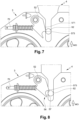
- connection phase for the transition from the disconnected configuration to the connected configuration, with reference to the Figures 5 to 10 .
- the upper block 4 in the disconnected configuration, the upper block 4 is suspended above the lower block 3 and the latch 52 is in the neutral position, with the thrust stop 70 in the maximum advanced position.
- the lower block 3 begins by being raised, as shown schematically by the arrow MO, for a relative ruzement between the two blocks 3, 4, until, with reference to the Figure 6 , the locking member 62 enters the locking channel 53 through the mouth 54 and comes into contact with the proximal edge 571 of the latch 52, thus bringing the upper block 4 to the upper stop on the boom, and more specifically until the upper stop 43 of the upper block 4 is in abutment against the distributor carriage 9.
- the locking member 62 exerts a thrust on the proximal edge 571 of the latch 52, while sliding inside the locking channel 53 in the entry direction (downwards), to bring the latch 52 into the distal position in which the locking member 62 rests on the proximal tip 573 (see Figure 7 ), then the locking member 62 exceeds the proximal tip 573 of the latch 52 (see Figure 8 ), and then the latch 52 leaves contact with the proximal tip 573 (see Figure 9 ) and pivots in the proximal direction of rotation (upwards) under the effect of a thrust exerted by the thrust device 7, until the distal edge 572 of the latch 52 in turn comes into contact with the locking member 62, as shown diagrammatically in Figure 9 .
- the locking member 62 is engaged inside the free end 56 of the latch 52.
- the lower block 3 is then moved downward, as shown diagrammatically by the arrow DE, so that the locking member 62 slides inside the locking channel 53 in the exit direction (upwards), and brings the latch 52 into the locking position, until the locking member 62 is wedged inside the free end 56 of the latch 52 and is therefore blocked in sliding in the locking channel 53 in the exit direction, and thus the lower block 3 and the upper block 4 are connected.
- the thrust stop 70 is in the connection setback position, and the mark 83 corresponds to the visual connection reference 84, which allows the operator to visualize the connection and thus continue the descent of the lower block 3 with the upper block 4 in the connected configuration. It is also possible, if this option is present, to use the removable stop 20 to lock the connected configuration.
- the latch 52 in the connected configuration, the latch 52 is in the locking position and the locking member 62 is stuck inside the free end 56 of the latch 52, more precisely with the locking member 62 stuck inside the notch 57 of this free end 56.
- the thrust stop 70 is then in its connection retracted position, and the mark 83 corresponds to the visual connection reference 84.
- the lower block 3 can be lowered together with the upper block 4. Indeed, when the lower block 3 descends with its latch 52, this latch 52 is blocked by the locking member 62 and cannot pivot to the proximal position according to the proximal rotation direction (pivoting upwards). Thus, the latch 52 remains blocked in the locking position with the locking member 62 which, as a reminder, is integral with the upper block 4.
- the upper block 4 is therefore connected to the lower block 3 and therefore descends with it.
- the lower block 3 is first mounted (with the upper block 4), as shown by the arrow MO, until the upper block 4 is at the top stop on the arrow, and more specifically until that the upper stop 43 of the upper block 4 is in abutment against the distributor carriage 9.
- the latch 52 pivots downwards, while the locking member 62 slides towards the bottom 55, until the locking member 62 leaves the interior of the free end 56 of the latch 52, passes the distal tip 574 and finally leaves contact with the latch 52, and then, as illustrated in Figure 14 , the latch 52 returns to the neutral position under the effect of the thrust exerted by the thrust device 7, and the locking member 62 is under the latch 52 (or even is arranged in the bottom 55 of the locking channel 53).
- the thrust stop 70 moves back under the effect of the pivoting of the latch 52 until it reaches the intermediate distal position when the locking member 62 is resting on the distal tip 574, then the thrust stop 70 moves forward to return the latch 52 to the neutral position.
- the locking member 62 may remain stuck in the locking channel 53 by bearing on the distal tip 574, which corresponds to the second unstable configuration in which the latch 62 is in the second unstable position described above.
- the use of the lower pushing device 10 and the lower viewing means previously described are practical to allow an operator to view this jamming in order to remedy it.
- the lower block 3 is moved downwards, as shown diagrammatically by the arrow DE, so that the locking member 62 slides inside the locking channel 53 in the exit direction (upwards), until it comes to bear against the distal edge 572 of the latch 52, thus pushing the latch 52 which then pivots in the proximal direction of rotation (upwards) until it reaches the proximal position, as illustrated in Figure 16 , thereby allowing the locking member 62 to exit the locking channel 53 and disengage from the latches 52.
- the thrust stop 70 remains at all times in its maximum advanced position, the latch 52 leaving contact with its free front end 71 by pivoting towards the proximal position.
- the latch 52 comes to bear against the proximal stop 79, which it crushes slightly under the stress exerted by the locking member 62.
- the locking member 62 is completely disengaged from the locking mechanism 5 and the latch 52 has returned to the neutral position under the effect of the proximal stop 79 and its own weight, and thus the lower block 3 and the upper block 4 are disconnected.
- the thrust stop 70 is in the disconnection retraction position, and the mark 83 corresponds to the visual disconnection reference 81 or 85, which allows the operator to visualize the disconnection and thus continue the descent of the lower block 3 alone in the disconnected configuration, without the upper block 4 which remains at the level of the distributor carriage 9.
- connection phase in the connection phase and in the disconnection phase, only the control of the raising/lowering movements of the lower block 3 makes it possible to switch from a connected configuration to the disconnected configuration, and vice versa.
- the control of the raising/lowering movements of the lower block 3 is carried out by controlling the lifting winch.
- connection and disconnection phases it is advantageous to automate the movements of the lower block 3, in the connection phase and in the disconnection phase, by means of a control/command unit which controls the lifting winch.
- a control/command unit which controls the lifting winch.
- sensors for detecting relative positions between the lower block 3 and the upper block 4 such as for example a sensor for detecting when the upper block 4 is at the top stop on the boom, and more specifically when the upper stop 43 of the upper block 4 is at the stop against the distributor carriage 9. Indeed, this position constitutes a starting point for the movements which will follow in the connection and disconnection phases.
Landscapes
- Engineering & Computer Science (AREA)
- Mechanical Engineering (AREA)
- Automation & Control Theory (AREA)
- Jib Cranes (AREA)
- Load-Engaging Elements For Cranes (AREA)
- Combined Means For Separation Of Solids (AREA)
Claims (15)
- Hebevorrichtung mit Doppel-Flaschenzug (1) für eine Hebemaschine, wie zum Beispiel einen Kran, umfassend zwei Flaschenzüge (3, 4), nämlich einen unteren Flaschenzug (3), der an einem Hebehaken (30) befestigt ist, und einen oberen Flaschenzug (4), wobei die beiden Flaschenzüge (3, 4) ein mechanisches reversibles Verbindungssystem umfassen, um reversibel zwischen Folgendem konfigurierbar zu sein:- einer verbundenen Konfiguration, bei der der obere Flaschenzug (4) mit dem unteren Flaschenzug (3) verbunden ist, um ihn bei Auf- und Abwärtsbewegungen entlang einer Hauptachse begleiten zu können, und- einer getrennten Konfiguration, bei der der obere Flaschenzug (4) vom unteren Flaschenzug (3) getrennt ist, um über dem unteren Flaschenzug (3) hängen bleiben zu können, der die Auf- und Abwärtsbewegungen ohne den oberen Flaschenzug (4) ausführen kann,wobei das mechanische reversible Verbindungssystem einen Verriegelungsmechanismus (5), der an einem der beiden Flaschenzüge (3, 4) montiert ist, und eine komplementäre Verriegelungsstruktur (6) umfasst, die an dem anderen der beiden Flaschenzüge (3, 4) montiert ist und ein Verriegelungselement (62) umfasst, das dazu geeignet ist, mit dem Verriegelungsmechanismus (5) zusammenzuwirken;und wobei der Verriegelungsmechanismus (5) Folgendes umfasst:- einen Rahmen (50), der einen Verriegelungskanal (53) mit länglicher Form entlang der Hauptachse aufweist und mit einer Mündung (54) versehen ist, durch die das Verriegelungselement (62) in den Verriegelungskanal (53) eintreten und austreten kann und in dem Verriegelungskanal (53) in einer Eintrittsrichtung und in einer Austrittsrichtung, die der Eintrittsrichtung entgegengesetzt ist, bei einer relativen Annäherung bzw. einer relativen Entfernung zwischen den beiden Flaschenzügen (3, 4) gleiten kann, und- mindestens eine Sperrklinke (52), die schwenkbar am Rahmen (50) entlang einer Schwenkachse montiert ist, um in den Verriegelungskanal (53) einzurasten, wobei die Sperrklinke (52) mit einem freien Ende (56) versehen ist, das dazu geeignet ist, mit dem Verriegelungselement (62) in Eingriff zu stehen,wobei der Verriegelungsmechanismus (5) dadurch gekennzeichnet ist, dass er ferner Folgendes umfasst:- einen Schubanschlag (70), der mit einem freien vorderen Ende (71) versehen ist, das dazu geeignet ist, gegen die Sperrklinke (52) anzustoßen, wobei der Schubanschlag (70) beweglich am Rahmen (50) zwischen einer maximal vorgeschobenen Position bei Nichtvorhandensein eines Schubs, der von der Sperrklinke (52) auf das freie vordere Ende ausgeübt wird, und zurückgezogenen Positionen bei Vorhandensein einer Schubkraft, die von der Sperrklinke (52) auf das freie vordere Ende ausgeübt wird, montiert ist; und- ein elastisches Rückstellelement (74), das den Schubanschlag (70) in seine maximal vorgeschobene Position drängt und eine Kraft bereitstellt, die einer Schubkraft standhält, die von der Sperrklinke (52) auf das freie vordere Ende ausgeübt wird.
- Hebevorrichtung mit Doppel-Flaschenzug (1) nach Anspruch 1, wobei der Schubanschlag (70) translatorisch gleitend am Rahmen (50) montiert ist.
- Hebevorrichtung mit Doppel-Flaschenzug (1) nach Anspruch 1 oder 2, die ein Sichtmittel (8) umfasst, das dazu konfiguriert ist, anzuzeigen, ob sich der Schubanschlag (70) in seiner maximal vorgeschobenen Position befindet, die der getrennten Konfiguration zugeordnet ist, oder in einer seiner zurückgezogenen Positionen, der sogenannten zurückgezogenen Verbindungsposition, die der verbundenen Konfiguration zugeordnet ist.
- Hebevorrichtung mit Doppel-Flaschenzug (1) nach Anspruch 3, wobei das Sichtmittel (8) dazu konfiguriert ist, anzuzeigen, ob sich der Schubanschlag (70) in einer anderen der zurückgezogenen Positionen, der sogenannten instabilen zurückgezogenen Position, befindet, die einer instabilen Konfiguration zugeordnet ist, bei der sich der Schubanschlag (70) über die zurückgezogene Verbindungsposition hinaus zurückgezogen hat.
- Hebevorrichtung mit Doppel-Flaschenzug (1) nach Anspruch 3 oder 4, wobei das Sichtmittel (8) ein im Rahmen ausgebildetes Fenster (80) umfasst, um eine auf dem Schubanschlag (70) vorgesehene Markierung (83) in der maximal vorgeschobenen Position oder in der zurückgezogenen Verbindungsposition zu sehen.
- Hebevorrichtung mit Doppel-Flaschenzug (1) nach Anspruch 5, wobei das Sichtmittel (8) an dem Rahmen (50) mindestens eine visuelle Referenz (81; 84; 85) umfasst, die visuell mit der Markierung (83) des Schubanschlags (70) übereinstimmt, wenn sich der Schubanschlag (70) in seiner maximal vorgeschobenen Position oder in seiner zurückgezogenen Verbindungsposition befindet.
- Hebevorrichtung mit Doppel-Flaschenzug (1) nach Anspruch 6, wobei die mindestens eine visuelle Referenz eine visuelle Verbindungsreferenz (84), die visuell mit der Markierung (83) des Schubanschlags (70) übereinstimmt, wenn sich der Schubanschlag (70) in seiner maximal vorgeschobenen Position befindet, und eine visuelle Trennungsreferenz (81; 85) umfasst, die visuell mit der Markierung (83) des Schubanschlags (70) übereinstimmt, wenn sich der Schubanschlag (70) in seiner zurückgezogenen Verbindungsposition befindet.
- Hebevorrichtung mit Doppel-Flaschenzug (1) nach Anspruch 3, wobei das Sichtmittel mindestens einen Positionssensor, der dazu konfiguriert ist, den Schubanschlag (70) mindestens in seiner maximal vorgeschobenen Position und in seiner zurückgezogenen Verbindungsposition zu detektieren, und ein mit dem Positionssensor verbundenes Anzeigemittel umfasst, um die Position des Schubanschlags (70) in Abhängigkeit von einer Detektion durch den Positionssensor anzuzeigen.
- Hebevorrichtung mit Doppel-Flaschenzug (1) nach einem der Ansprüche 1 bis 8, wobei die Sperrklinke (52) zwischen Folgendem schwenkbar beweglich ist:- einer neutralen Position, in der sich der Schubanschlag (70) in seiner maximal vorgeschobenen Position befindet, wobei sein freies vorderes Ende (71) im Ruhezustand in Kontakt mit der Sperrklinke (52) steht;- einer distalen Position, in der die Sperrklinke (52) den Durchgang für das Verriegelungselement (62) unter der Wirkung eines Schubs freigibt, der durch das Gleiten des Verriegelungselements (62) in der Eintrittsrichtung ausgeübt wird, wobei die distale Position einem Schwenken der Sperrklinke (52) in einer distalen Drehrichtung ausgehend von der neutralen Position zugeordnet ist, wobei die Sperrklinke (52) somit eine Schubkraft auf das freie vordere Ende (71) des Schubanschlags (70) ausübt, der in eine seiner zurückgezogenen Positionen, die sogenannte maximal zurückgezogene Position, gedrückt wird;- einer proximalen Position, in der die Sperrklinke (52) den Durchgang für das Verriegelungselement (62) unter der Wirkung eines Schubs freigibt, der durch das Gleiten des Verriegelungselements (62) in Austrittsrichtung ausgeübt wird, wobei die proximale Position einem Schwenken der Sperrklinke (52) in eine proximale Drehrichtung, die der distalen Drehrichtung entgegengesetzt ist, ausgehend von der neutralen Position zugeordnet ist, wobei die Sperrklinke (52) nicht mehr in Kontakt mit dem freien vorderen Ende (71) des Schubanschlags (70) steht, der sich dann in seiner maximal vorgeschobenen Position befindet; und- einer Verriegelungsposition, die zwischen der neutralen Position und der distalen Position liegt, wobei das freie Ende (56) der Sperrklinke (52) das Verriegelungselement (62) beim Gleiten im Verriegelungskanal (53) in der Austrittsrichtung blockiert, wobei das Verriegelungselement (62) innerhalb des freien Endes (56) festsitzt, wobei die Sperrklinke (52) somit eine Schubkraft auf das freie vordere Ende (71) des Schubanschlags (70) ausübt, der in einer seiner zurückgezogenen Positionen, der sogenannten zurückgezogenen Verbindungsposition, die sich zwischen der maximal zurückgezogenen Position und der maximal vorgeschobenen Position befindet, blockiert wird.
- Hebevorrichtung mit Doppel-Flaschenzug (1) nach einem der Ansprüche 1 bis 9, die ferner einen entfernbaren Anschlag (20) umfasst, der an dem Rahmen (50) in einer Blockierposition bewegbar ist, in der der entfernbare Anschlag das Schwenken der Sperrklinke (52) blockiert, wenn sie in der verbundenen Konfiguration mit dem Verriegelungselement (62) in Eingriff steht.
- Hebevorrichtung mit Doppel-Flaschenzug (1) nach Anspruch 10, wobei der entfernbare Anschlag (20) auch an dem Rahmen (50) in einer Lagerungsposition beweglich ist, in der sich der entfernbare Anschlag von der Sperrklinke (52) entfernt befindet, um nicht mit der Sperrklinke zusammenzuwirken.
- Hebevorrichtung mit Doppel-Flaschenzug (1) nach einem der Ansprüche 1 bis 11, die ferner einen unteren Anschlag (11) umfasst, der in einem Boden (55) des Verriegelungskanals (53), gegenüber der Mündung (54), angeordnet ist und gegen den das Verriegelungselement (62) anstoßen kann, wobei der untere Anschlag (11) beweglich am Rahmen (50) zwischen einer angehobenen Position bei Nichtvorhandensein eines Schubs, der vom Verriegelungselement auf den unteren Anschlag (11) ausgeübt wird, und abgesenkten Positionen bei Vorhandensein einer Schubkraft, die vom Verriegelungselement auf den unteren Anschlag (11) ausgeübt wird, montiert ist; und- ein unteres elastisches Rückstellelement, das den unteren Anschlag (11) in seine angehobene Position drängt und eine Kraft bereitstellt, die einer Schubkraft standhält, die vom Verriegelungselement auf den unteren Anschlag ausgeübt wird.
- Hebevorrichtung mit Doppel-Flaschenzug (1) nach Anspruch 12, wobei der untere Anschlag (11) entlang der Hauptachse translatorisch gleitend am Rahmen (50) montiert ist.
- Hebevorrichtung mit Doppel-Flaschenzug (1) nach Anspruch 12 oder 13, die ein unteres Sichtmittel (13; 14) umfasst, das dazu konfiguriert ist, anzuzeigen, ob sich der untere Anschlag (11) in seiner angehobenen Position befindet, die der verbundenen Konfiguration zugeordnet ist, oder in einer seiner abgesenkten Positionen, der sogenannten instabilen abgesenkten Position, die einer instabilen Konfiguration zugeordnet ist, bei der das Verriegelungselement unter der Sperrklinke festsitzt.
- Hebemaschine, wie zum Beispiel ein Kran, die einen Ausleger und eine Hebevorrichtung mit Doppel-Flaschenzug (1) umfasst, die dazu ausgebildet ist, eine Last entlang des Auslegers anzuheben/herabzulassen, wobei die Hebevorrichtung mit Doppel-Flaschenzug (1) einem der vorhergehenden Ansprüche entspricht, wobei ein unterer Flaschenzug (3) durch ein Hebeseil (90), das mit einem Hubwerk verbunden ist, aufgehängt ist, um den unteren Flaschenzug (3) hochzuziehen/herabzulassen, wobei das Hebeseil (90) durch den oberen Flaschenzug (4) verläuft.
Applications Claiming Priority (1)
| Application Number | Priority Date | Filing Date | Title |
|---|---|---|---|
| FR2204233A FR3135259B1 (fr) | 2022-05-04 | 2022-05-04 | Dispositif de levage à double mouflage avec mécanisme amélioré de verrouillage à loquet |
Publications (2)
| Publication Number | Publication Date |
|---|---|
| EP4273085A1 EP4273085A1 (de) | 2023-11-08 |
| EP4273085B1 true EP4273085B1 (de) | 2024-09-04 |
Family
ID=82100469
Family Applications (1)
| Application Number | Title | Priority Date | Filing Date |
|---|---|---|---|
| EP23170289.5A Active EP4273085B1 (de) | 2022-05-04 | 2023-04-27 | Doppelblasheber mit verbessertem verriegelungsmechanismus |
Country Status (4)
| Country | Link |
|---|---|
| US (1) | US12371308B2 (de) |
| EP (1) | EP4273085B1 (de) |
| ES (1) | ES3005452T3 (de) |
| FR (1) | FR3135259B1 (de) |
Family Cites Families (20)
| Publication number | Priority date | Publication date | Assignee | Title |
|---|---|---|---|---|
| US1436608A (en) * | 1921-08-10 | 1922-11-21 | Robert S Rodier | Block and tackle apparatus |
| US3009728A (en) * | 1958-07-17 | 1961-11-21 | Breslav Jack | Rotatable load supporting or lifting device |
| FR1451362A (fr) * | 1965-06-22 | 1966-01-07 | Richier Sa | Perfectionnement aux dispositifs de mouflage utilisés pour le levage des charges |
| FR1520612A (fr) | 1967-02-22 | 1968-04-12 | Potain & Cie Ets F | Dispositif pour augmenter la charge et la portée maxima d'une flèche de grue distributrice |
| DE2116544A1 (de) | 1971-04-05 | 1972-11-23 | F.B. Kroell A/S, Roedovre (Dänemark) | Umschervorrichtung für Windwerke mit einer mehrsträngig aufgehängten Unterflasche |
| FR2137333B1 (de) | 1971-05-12 | 1976-03-19 | Potain Sa | |
| FR2228024A1 (en) | 1973-05-02 | 1974-11-29 | Richier Sa | Changeover for tower crane lifting hook - latch changes four strand pulley system to two strand |
| FR2333743A1 (fr) | 1975-12-01 | 1977-07-01 | Pingon Manubat Sa | Chariot distributeur pour appareils de levage |
| FR2368431A1 (fr) | 1976-10-22 | 1978-05-19 | Potain Sa | Double mouflage automatique pour le chariot distributeur d'une grue a tour |
| DE2845874C2 (de) * | 1978-10-21 | 1982-03-25 | Elba Maschinenfabrik Kaiser GmbH & Co, 6670 St Ingbert | Vorrichtung zum Umscheren des Hubseiles bei Kränen |
| DE3149690A1 (de) | 1981-12-15 | 1983-06-23 | Liebherr-Werk Biberach Gmbh, 7950 Biberach | Vorrichtung zum umscheren des hubseils bei kranen |
| DE3515156A1 (de) | 1985-04-26 | 1986-10-30 | M.A.N.-Wolffkran GmbH, 7100 Heilbronn | Vorrichtung zum umscheren des hubseils bei einem kran mit einer auf einer hochgelegenen laufbahn verfahrbaren laufkatze |
| DE3543214A1 (de) | 1985-06-13 | 1986-12-18 | Liebherr-Werk Bischofshofen GmbH, Bischofshofen | Vorrichtung zum umscheren der durch ein seil mit der laufkatze eines krans verbundenen unterflasche des kranhakens |
| US4721286A (en) * | 1985-07-24 | 1988-01-26 | Amca International Corporation | Split block for extended travel |
| US20050127695A1 (en) * | 2003-12-10 | 2005-06-16 | Cranston Diversified Industries, Inc. | Remote controlled load lifting hook and methods |
| US7946560B2 (en) * | 2009-02-25 | 2011-05-24 | Manitowoc Crane Companies, Llc | Crane hook block |
| ITMI20101302A1 (it) * | 2010-07-15 | 2012-01-16 | F B F Lli Butti S R L | Dispositivo per variare automaticamente il sistema di taglia in apparecchi sollevatori, particolarmente per gru a torre. |
| CN208761990U (zh) * | 2018-08-16 | 2019-04-19 | 上海海迅机电工程有限公司 | 一种用于吊具的自调整定位锁紧吊钩 |
| FR3114090B1 (fr) * | 2020-09-16 | 2022-08-19 | Manitowoc Crane Group France | Dispositif de levage à double mouflage avec mécanisme de verrouillage à loquet |
| FR3114089B1 (fr) * | 2020-09-17 | 2022-08-19 | Manitowoc Crane Group France | Dispositif de levage à double mouflage avec mécanisme de verrouillage rotatif |
-
2022
- 2022-05-04 FR FR2204233A patent/FR3135259B1/fr active Active
-
2023
- 2023-04-27 ES ES23170289T patent/ES3005452T3/es active Active
- 2023-04-27 EP EP23170289.5A patent/EP4273085B1/de active Active
- 2023-05-01 US US18/310,211 patent/US12371308B2/en active Active
Also Published As
| Publication number | Publication date |
|---|---|
| FR3135259B1 (fr) | 2024-05-03 |
| US20230356988A1 (en) | 2023-11-09 |
| EP4273085A1 (de) | 2023-11-08 |
| ES3005452T3 (en) | 2025-03-14 |
| US12371308B2 (en) | 2025-07-29 |
| FR3135259A1 (fr) | 2023-11-10 |
Similar Documents
| Publication | Publication Date | Title |
|---|---|---|
| EP4049960B1 (de) | Hubvorrichtung mit doppelter einscherung und drehverriegelungsmechanismus mit schnappschloss | |
| EP0621157B1 (de) | Gerät, das einem Fahrzeug ermöglicht, eine Ladung, wie z.B. einen Kübel, aufzunehmen oder auf dem Boden abzusetzen und ihn evtl. zu entleeren | |
| FR3068026A1 (fr) | Dispositif pour la manutention d'objet | |
| FR2774639A1 (fr) | Dispositif, appareil et procede pour permettre a un vehicule de prendre ou de poser au sol une charge presentant un moyen de prehension a l'avant | |
| EP0194954A1 (de) | Vorrichtung zur Förderung und Verschiebung einer Last, z.B. eines Containers oder eines Kipperaufbaus auf einem Fahrzeug | |
| WO2020079054A1 (fr) | Porte d'aéronef à soulèvement supplémentaire de sécurité | |
| EP4273085B1 (de) | Doppelblasheber mit verbessertem verriegelungsmechanismus | |
| EP4023585B1 (de) | Hubvorrichtung mit doppelter einscherung und drehverriegelungsmechanismus | |
| WO2018115606A1 (fr) | Grue de levage comprenant un dispositif de levage à double mouflage | |
| EP3898482B1 (de) | Absturzsicherung für motorgetriebene zahnstangenaufzüge | |
| EP4345052B1 (de) | Hebezeug mit automatisierter änderung der schlichtkonfiguration | |
| EP2109575A2 (de) | Vorrichtung zur lagerung von objekten auf einer mobilen palette | |
| EP0340076A1 (de) | Vorrichtung zum Halten und Laden von länglichen Gegenständen, insbesondere Leitern auf dem Dach eines Fahrzeuges | |
| FR2753387A1 (fr) | Dispositif de support mobile pour devidoir de tuyau | |
| FR3010988A1 (fr) | Conteneur de collecte des dechets dote d’un systeme perfectionne de commande d'ouverture/fermeture automatique de trappe de vidage | |
| FR2955135A1 (fr) | Mat articule extensible a charniere demontable | |
| EP0612899A1 (de) | Gerüstboden und Montageverfahren für Gerüste mit diesem Boden | |
| EP4049959B1 (de) | Verfahren zur sicherung eines kippbaren auslegerkrans, um die winkelposition des kippbaren auslegers abzusichern | |
| WO2018115607A1 (fr) | Grue de levage comprenant un dispositif de levage à double mouflage | |
| EP0008253A1 (de) | Automatische Greifvorrichtung | |
| WO2001083330A1 (fr) | Leve-conteneurs a verrou automatique de retenue | |
| FR2549785A1 (fr) | Dispositif a bras articules pour la manoeuvre d'une benne sur un vehicule | |
| FR2709743A1 (fr) | Crochet pour soulever des charges et les larguer au-dessus du sol. | |
| FR2524404A1 (fr) | Plate-forme elevatrice, notamment pour vehicule industriel | |
| FR2720040A1 (fr) | Véhicule à benne amovible. |
Legal Events
| Date | Code | Title | Description |
|---|---|---|---|
| PUAI | Public reference made under article 153(3) epc to a published international application that has entered the european phase |
Free format text: ORIGINAL CODE: 0009012 |
|
| STAA | Information on the status of an ep patent application or granted ep patent |
Free format text: STATUS: THE APPLICATION HAS BEEN PUBLISHED |
|
| AK | Designated contracting states |
Kind code of ref document: A1 Designated state(s): AL AT BE BG CH CY CZ DE DK EE ES FI FR GB GR HR HU IE IS IT LI LT LU LV MC ME MK MT NL NO PL PT RO RS SE SI SK SM TR |
|
| STAA | Information on the status of an ep patent application or granted ep patent |
Free format text: STATUS: REQUEST FOR EXAMINATION WAS MADE |
|
| 17P | Request for examination filed |
Effective date: 20240410 |
|
| RBV | Designated contracting states (corrected) |
Designated state(s): AL AT BE BG CH CY CZ DE DK EE ES FI FR GB GR HR HU IE IS IT LI LT LU LV MC ME MK MT NL NO PL PT RO RS SE SI SK SM TR |
|
| GRAP | Despatch of communication of intention to grant a patent |
Free format text: ORIGINAL CODE: EPIDOSNIGR1 |
|
| STAA | Information on the status of an ep patent application or granted ep patent |
Free format text: STATUS: GRANT OF PATENT IS INTENDED |
|
| INTG | Intention to grant announced |
Effective date: 20240523 |
|
| GRAS | Grant fee paid |
Free format text: ORIGINAL CODE: EPIDOSNIGR3 |
|
| GRAA | (expected) grant |
Free format text: ORIGINAL CODE: 0009210 |
|
| STAA | Information on the status of an ep patent application or granted ep patent |
Free format text: STATUS: THE PATENT HAS BEEN GRANTED |
|
| AK | Designated contracting states |
Kind code of ref document: B1 Designated state(s): AL AT BE BG CH CY CZ DE DK EE ES FI FR GB GR HR HU IE IS IT LI LT LU LV MC ME MK MT NL NO PL PT RO RS SE SI SK SM TR |
|
| REG | Reference to a national code |
Ref country code: GB Ref legal event code: FG4D Free format text: NOT ENGLISH |
|
| REG | Reference to a national code |
Ref country code: CH Ref legal event code: EP |
|
| REG | Reference to a national code |
Ref country code: IE Ref legal event code: FG4D Free format text: LANGUAGE OF EP DOCUMENT: FRENCH |
|
| REG | Reference to a national code |
Ref country code: DE Ref legal event code: R096 Ref document number: 602023000494 Country of ref document: DE |
|
| REG | Reference to a national code |
Ref country code: LT Ref legal event code: MG9D |
|
| REG | Reference to a national code |
Ref country code: NL Ref legal event code: MP Effective date: 20240904 |
|
| PG25 | Lapsed in a contracting state [announced via postgrant information from national office to epo] |
Ref country code: NO Free format text: LAPSE BECAUSE OF FAILURE TO SUBMIT A TRANSLATION OF THE DESCRIPTION OR TO PAY THE FEE WITHIN THE PRESCRIBED TIME-LIMIT Effective date: 20241204 |
|
| PG25 | Lapsed in a contracting state [announced via postgrant information from national office to epo] |
Ref country code: GR Free format text: LAPSE BECAUSE OF FAILURE TO SUBMIT A TRANSLATION OF THE DESCRIPTION OR TO PAY THE FEE WITHIN THE PRESCRIBED TIME-LIMIT Effective date: 20241205 Ref country code: FI Free format text: LAPSE BECAUSE OF FAILURE TO SUBMIT A TRANSLATION OF THE DESCRIPTION OR TO PAY THE FEE WITHIN THE PRESCRIBED TIME-LIMIT Effective date: 20240904 |
|
| PG25 | Lapsed in a contracting state [announced via postgrant information from national office to epo] |
Ref country code: BG Free format text: LAPSE BECAUSE OF FAILURE TO SUBMIT A TRANSLATION OF THE DESCRIPTION OR TO PAY THE FEE WITHIN THE PRESCRIBED TIME-LIMIT Effective date: 20240904 |
|
| PG25 | Lapsed in a contracting state [announced via postgrant information from national office to epo] |
Ref country code: LV Free format text: LAPSE BECAUSE OF FAILURE TO SUBMIT A TRANSLATION OF THE DESCRIPTION OR TO PAY THE FEE WITHIN THE PRESCRIBED TIME-LIMIT Effective date: 20240904 |
|
| PG25 | Lapsed in a contracting state [announced via postgrant information from national office to epo] |
Ref country code: HR Free format text: LAPSE BECAUSE OF FAILURE TO SUBMIT A TRANSLATION OF THE DESCRIPTION OR TO PAY THE FEE WITHIN THE PRESCRIBED TIME-LIMIT Effective date: 20240904 |
|
| PG25 | Lapsed in a contracting state [announced via postgrant information from national office to epo] |
Ref country code: RS Free format text: LAPSE BECAUSE OF FAILURE TO SUBMIT A TRANSLATION OF THE DESCRIPTION OR TO PAY THE FEE WITHIN THE PRESCRIBED TIME-LIMIT Effective date: 20241204 |
|
| PG25 | Lapsed in a contracting state [announced via postgrant information from national office to epo] |
Ref country code: RS Free format text: LAPSE BECAUSE OF FAILURE TO SUBMIT A TRANSLATION OF THE DESCRIPTION OR TO PAY THE FEE WITHIN THE PRESCRIBED TIME-LIMIT Effective date: 20241204 Ref country code: NO Free format text: LAPSE BECAUSE OF FAILURE TO SUBMIT A TRANSLATION OF THE DESCRIPTION OR TO PAY THE FEE WITHIN THE PRESCRIBED TIME-LIMIT Effective date: 20241204 Ref country code: LV Free format text: LAPSE BECAUSE OF FAILURE TO SUBMIT A TRANSLATION OF THE DESCRIPTION OR TO PAY THE FEE WITHIN THE PRESCRIBED TIME-LIMIT Effective date: 20240904 Ref country code: HR Free format text: LAPSE BECAUSE OF FAILURE TO SUBMIT A TRANSLATION OF THE DESCRIPTION OR TO PAY THE FEE WITHIN THE PRESCRIBED TIME-LIMIT Effective date: 20240904 Ref country code: GR Free format text: LAPSE BECAUSE OF FAILURE TO SUBMIT A TRANSLATION OF THE DESCRIPTION OR TO PAY THE FEE WITHIN THE PRESCRIBED TIME-LIMIT Effective date: 20241205 Ref country code: FI Free format text: LAPSE BECAUSE OF FAILURE TO SUBMIT A TRANSLATION OF THE DESCRIPTION OR TO PAY THE FEE WITHIN THE PRESCRIBED TIME-LIMIT Effective date: 20240904 Ref country code: BG Free format text: LAPSE BECAUSE OF FAILURE TO SUBMIT A TRANSLATION OF THE DESCRIPTION OR TO PAY THE FEE WITHIN THE PRESCRIBED TIME-LIMIT Effective date: 20240904 |
|
| REG | Reference to a national code |
Ref country code: AT Ref legal event code: MK05 Ref document number: 1720225 Country of ref document: AT Kind code of ref document: T Effective date: 20240904 |
|
| PG25 | Lapsed in a contracting state [announced via postgrant information from national office to epo] |
Ref country code: NL Free format text: LAPSE BECAUSE OF FAILURE TO SUBMIT A TRANSLATION OF THE DESCRIPTION OR TO PAY THE FEE WITHIN THE PRESCRIBED TIME-LIMIT Effective date: 20240904 |
|
| REG | Reference to a national code |
Ref country code: ES Ref legal event code: FG2A Ref document number: 3005452 Country of ref document: ES Kind code of ref document: T3 Effective date: 20250314 |
|
| PG25 | Lapsed in a contracting state [announced via postgrant information from national office to epo] |
Ref country code: PT Free format text: LAPSE BECAUSE OF FAILURE TO SUBMIT A TRANSLATION OF THE DESCRIPTION OR TO PAY THE FEE WITHIN THE PRESCRIBED TIME-LIMIT Effective date: 20250106 Ref country code: IS Free format text: LAPSE BECAUSE OF FAILURE TO SUBMIT A TRANSLATION OF THE DESCRIPTION OR TO PAY THE FEE WITHIN THE PRESCRIBED TIME-LIMIT Effective date: 20250104 |
|
| PG25 | Lapsed in a contracting state [announced via postgrant information from national office to epo] |
Ref country code: RO Free format text: LAPSE BECAUSE OF FAILURE TO SUBMIT A TRANSLATION OF THE DESCRIPTION OR TO PAY THE FEE WITHIN THE PRESCRIBED TIME-LIMIT Effective date: 20240904 Ref country code: SM Free format text: LAPSE BECAUSE OF FAILURE TO SUBMIT A TRANSLATION OF THE DESCRIPTION OR TO PAY THE FEE WITHIN THE PRESCRIBED TIME-LIMIT Effective date: 20240904 |
|
| PG25 | Lapsed in a contracting state [announced via postgrant information from national office to epo] |
Ref country code: EE Free format text: LAPSE BECAUSE OF FAILURE TO SUBMIT A TRANSLATION OF THE DESCRIPTION OR TO PAY THE FEE WITHIN THE PRESCRIBED TIME-LIMIT Effective date: 20240904 Ref country code: AT Free format text: LAPSE BECAUSE OF FAILURE TO SUBMIT A TRANSLATION OF THE DESCRIPTION OR TO PAY THE FEE WITHIN THE PRESCRIBED TIME-LIMIT Effective date: 20240904 |
|
| PG25 | Lapsed in a contracting state [announced via postgrant information from national office to epo] |
Ref country code: CZ Free format text: LAPSE BECAUSE OF FAILURE TO SUBMIT A TRANSLATION OF THE DESCRIPTION OR TO PAY THE FEE WITHIN THE PRESCRIBED TIME-LIMIT Effective date: 20240904 Ref country code: PL Free format text: LAPSE BECAUSE OF FAILURE TO SUBMIT A TRANSLATION OF THE DESCRIPTION OR TO PAY THE FEE WITHIN THE PRESCRIBED TIME-LIMIT Effective date: 20240904 |
|
| PG25 | Lapsed in a contracting state [announced via postgrant information from national office to epo] |
Ref country code: SK Free format text: LAPSE BECAUSE OF FAILURE TO SUBMIT A TRANSLATION OF THE DESCRIPTION OR TO PAY THE FEE WITHIN THE PRESCRIBED TIME-LIMIT Effective date: 20240904 |
|
| REG | Reference to a national code |
Ref country code: DE Ref legal event code: R097 Ref document number: 602023000494 Country of ref document: DE |
|
| PGFP | Annual fee paid to national office [announced via postgrant information from national office to epo] |
Ref country code: DE Payment date: 20250422 Year of fee payment: 3 |
|
| PG25 | Lapsed in a contracting state [announced via postgrant information from national office to epo] |
Ref country code: DK Free format text: LAPSE BECAUSE OF FAILURE TO SUBMIT A TRANSLATION OF THE DESCRIPTION OR TO PAY THE FEE WITHIN THE PRESCRIBED TIME-LIMIT Effective date: 20240904 |
|
| PGFP | Annual fee paid to national office [announced via postgrant information from national office to epo] |
Ref country code: ES Payment date: 20250530 Year of fee payment: 3 |
|
| PLBE | No opposition filed within time limit |
Free format text: ORIGINAL CODE: 0009261 |
|
| STAA | Information on the status of an ep patent application or granted ep patent |
Free format text: STATUS: NO OPPOSITION FILED WITHIN TIME LIMIT |
|
| PGFP | Annual fee paid to national office [announced via postgrant information from national office to epo] |
Ref country code: IT Payment date: 20250430 Year of fee payment: 3 |
|
| PGFP | Annual fee paid to national office [announced via postgrant information from national office to epo] |
Ref country code: FR Payment date: 20250425 Year of fee payment: 3 |
|
| 26N | No opposition filed |
Effective date: 20250605 |
|
| PG25 | Lapsed in a contracting state [announced via postgrant information from national office to epo] |
Ref country code: SE Free format text: LAPSE BECAUSE OF FAILURE TO SUBMIT A TRANSLATION OF THE DESCRIPTION OR TO PAY THE FEE WITHIN THE PRESCRIBED TIME-LIMIT Effective date: 20240904 |
|
| PG25 | Lapsed in a contracting state [announced via postgrant information from national office to epo] |
Ref country code: LU Free format text: LAPSE BECAUSE OF NON-PAYMENT OF DUE FEES Effective date: 20250427 |
|
| PG25 | Lapsed in a contracting state [announced via postgrant information from national office to epo] |
Ref country code: MC Free format text: LAPSE BECAUSE OF FAILURE TO SUBMIT A TRANSLATION OF THE DESCRIPTION OR TO PAY THE FEE WITHIN THE PRESCRIBED TIME-LIMIT Effective date: 20240904 |
|
| REG | Reference to a national code |
Ref country code: BE Ref legal event code: MM Effective date: 20250430 |
|
| PG25 | Lapsed in a contracting state [announced via postgrant information from national office to epo] |
Ref country code: BE Free format text: LAPSE BECAUSE OF NON-PAYMENT OF DUE FEES Effective date: 20250430 |