EP4260775A1 - Stabilisateur pour stabiliser une vitre - Google Patents
Stabilisateur pour stabiliser une vitre Download PDFInfo
- Publication number
- EP4260775A1 EP4260775A1 EP23162241.6A EP23162241A EP4260775A1 EP 4260775 A1 EP4260775 A1 EP 4260775A1 EP 23162241 A EP23162241 A EP 23162241A EP 4260775 A1 EP4260775 A1 EP 4260775A1
- Authority
- EP
- European Patent Office
- Prior art keywords
- stabilizer
- holder
- channel
- screw
- clamping wedge
- Prior art date
- Legal status (The legal status is an assumption and is not a legal conclusion. Google has not performed a legal analysis and makes no representation as to the accuracy of the status listed.)
- Pending
Links
- 239000003381 stabilizer Substances 0.000 title claims abstract description 78
- 230000000087 stabilizing effect Effects 0.000 title claims abstract description 5
- 239000011521 glass Substances 0.000 title description 8
- 238000005192 partition Methods 0.000 claims abstract description 11
- 239000000463 material Substances 0.000 claims description 6
- 230000000717 retained effect Effects 0.000 claims 1
- 230000000875 corresponding effect Effects 0.000 description 4
- 230000006378 damage Effects 0.000 description 3
- 238000009434 installation Methods 0.000 description 3
- 238000004519 manufacturing process Methods 0.000 description 3
- 230000000295 complement effect Effects 0.000 description 2
- 208000027418 Wounds and injury Diseases 0.000 description 1
- 230000006978 adaptation Effects 0.000 description 1
- 238000004026 adhesive bonding Methods 0.000 description 1
- 238000010276 construction Methods 0.000 description 1
- 230000007423 decrease Effects 0.000 description 1
- 238000011161 development Methods 0.000 description 1
- 230000018109 developmental process Effects 0.000 description 1
- 208000014674 injury Diseases 0.000 description 1
- 238000003780 insertion Methods 0.000 description 1
- 230000037431 insertion Effects 0.000 description 1
Images


Classifications
-
- A—HUMAN NECESSITIES
- A47—FURNITURE; DOMESTIC ARTICLES OR APPLIANCES; COFFEE MILLS; SPICE MILLS; SUCTION CLEANERS IN GENERAL
- A47K—SANITARY EQUIPMENT NOT OTHERWISE PROVIDED FOR; TOILET ACCESSORIES
- A47K3/00—Baths; Douches; Appurtenances therefor
- A47K3/28—Showers or bathing douches
- A47K3/30—Screens or collapsible cabinets for showers or baths
-
- F—MECHANICAL ENGINEERING; LIGHTING; HEATING; WEAPONS; BLASTING
- F16—ENGINEERING ELEMENTS AND UNITS; GENERAL MEASURES FOR PRODUCING AND MAINTAINING EFFECTIVE FUNCTIONING OF MACHINES OR INSTALLATIONS; THERMAL INSULATION IN GENERAL
- F16B—DEVICES FOR FASTENING OR SECURING CONSTRUCTIONAL ELEMENTS OR MACHINE PARTS TOGETHER, e.g. NAILS, BOLTS, CIRCLIPS, CLAMPS, CLIPS OR WEDGES; JOINTS OR JOINTING
- F16B9/00—Connections of rods or tubular parts to flat surfaces at an angle
- F16B9/05—Connections of rods or tubular parts to flat surfaces at an angle by way of an intermediate member
- F16B9/054—Connections of rods or tubular parts to flat surfaces at an angle by way of an intermediate member the intermediate member being threaded
-
- F—MECHANICAL ENGINEERING; LIGHTING; HEATING; WEAPONS; BLASTING
- F16—ENGINEERING ELEMENTS AND UNITS; GENERAL MEASURES FOR PRODUCING AND MAINTAINING EFFECTIVE FUNCTIONING OF MACHINES OR INSTALLATIONS; THERMAL INSULATION IN GENERAL
- F16B—DEVICES FOR FASTENING OR SECURING CONSTRUCTIONAL ELEMENTS OR MACHINE PARTS TOGETHER, e.g. NAILS, BOLTS, CIRCLIPS, CLAMPS, CLIPS OR WEDGES; JOINTS OR JOINTING
- F16B9/00—Connections of rods or tubular parts to flat surfaces at an angle
- F16B9/05—Connections of rods or tubular parts to flat surfaces at an angle by way of an intermediate member
- F16B9/058—Connections of rods or tubular parts to flat surfaces at an angle by way of an intermediate member the intermediate member being secured to the rod by transverse fasteners
Definitions
- the present invention relates to a stabilizer for stabilizing a pane, in particular a shower partition, according to the preamble of claim 1 and a system with a stabilizer and a pane.
- stabilizers for stabilizing a pane or a shower partition are known from the prior art.
- showers often have a glass pane as a shower partition, one long side of which is attached to a wall and possibly also one short side to the floor.
- a problem here can be that strong forces act on the fastening devices used due to the relatively high weight of the shower partition or glass pane and the only one-sided or possibly two-sided fastening and/or that the fastening is not sufficiently stable. This poses a risk of damage to the shower partition and/or injury to a user if damage occurs.
- stabilizers are sometimes used to additionally hold or stabilize the pane or shower partition.
- such a stabilizer is essentially rod-like and has one end attached to a wall. At the other end, the stabilizer usually has a holder for holding the disk, in particular on its upper edge.
- the DE 20 2010 011 693 U1 relates to a bracing system for mounting real glass panes or other material panels in wet and residential areas as well as outdoors.
- the bracing is provided on the wall side with a wall mounting plate that is firmly connected to the wall.
- a holder is placed on the edge of the glass and secured by screwing in a screw. This screw presses a wedge into the clamp holder holder over a corresponding slope and thus presses the glass against a counter surface made of non-slip material, which is shaped to protect sensitive materials in such a way that the edge is not damaged.
- a stabilizer according to the invention is used to stabilize a pane.
- the pane is in particular a shower partition.
- the stabilizer according to the invention has a holder for holding the pane in a particularly clamping manner and a wall fastening part for attaching the stabilizer to a wall. Furthermore, the holder of the stabilizer has an at least substantially U-shaped receptacle for the disc.
- the stabilizer or holder has a tapered channel with a thread for receiving a screw. This is conducive to a simple structure of the holder or the stabilizer as well as simple assembly.
- the holder has a clamping wedge for clamping the pane.
- the holder preferably has a holding part.
- the clamping wedge is preferably held or maintained in a form-fitting manner in the holding part. This simplifies the assembly of the stabilizer, since the clamping wedge can first be inserted into the holding part or arranged on it in such a way that the clamping wedge is held in a form-fitting manner and cannot fall out of the holding part on its own. The disc can then be arranged in the holder or receptacle and clamped there without the clamping wedge having to be additionally secured.
- the two-part design of the holder with the clamping wedge and the holding part simplifies the production of the stabilizer or the holder.
- the channel preferably extends laterally next to the receptacle and/or essentially parallel to the receptacle. This achieves a large-area distribution of the clamping force, so that the point loads on the disc and the holder are minimized. This also makes assembly easier.
- the channel is preferably open at the top. This makes mounting the stabilizer easier because the disc extends essentially downwards and upwards from the holder side, so that the screw can simply be screwed into the channel from above without disturbing the washer or getting in the way.
- the holder is preferably designed so that the holder or a part thereof is deformed by screwing the screw into the channel, in particular in such a way that a disk arranged in the receptacle is clamped. In this way, a clamping hold of the pane in the holder can be achieved in a simple manner. This makes assembly easier.
- the clamping wedge preferably consists of a flexible material, in particular plastic.
- the clamping wedge is designed to deform when the screw is screwed into the channel and/or to clamp a disk arranged in the receptacle. This is conducive to easy assembly.
- the clamping wedge has or forms the U-shaped receptacle.
- the U-shaped receptacle in particular has or is formed by two opposing longitudinal segments and a transverse segment arranged between them.
- the clamping wedge preferably has a thread segment which has or forms the thread or at least a section thereof. This is conducive to simple construction and assembly.
- the thread segment is preferably arranged on one of the longitudinal segments and/or formed in one piece with it. This reduces the number of individual parts and thus simplifies production and assembly.
- the thread segment or its thread is preferably conical. This ensures a good hold of the screw in the thread and a stronger clamping of the washer as the screw is increasingly screwed into the channel. This allows for easy adjustment of the clamping force with which the disc is clamped.
- the channel is preferably formed between the clamping wedge and a counter surface opposite and/or assigned to the clamping wedge. This results in a simple structure.
- the counter surface preferably runs obliquely to a longitudinal axis of the channel. This makes the channel narrower in a simple way.
- the counter surface can have a threaded section and thus, in particular, form a thread together with the clamping wedge. However, this is not mandatory.
- the stabilizer preferably has the screw.
- the screw is designed as a grub screw. This enables the holder to be constructed in a space-saving manner, as no free space has to be provided for a screw head.
- a screw designed as a grub screw can be screwed completely into the channel so that it is not visible from the outside.
- the present invention also relates to a system with a stabilizer and a disk, the stabilizer being designed as described above and/or explained in more detail below.
- Fig. 1 shows a schematic perspective view of a proposed stabilizer 1.
- the stabilizer 1 is attached to a wall 2 and a disk 3 is held with the stabilizer 1 or a holder 3 of the stabilizer 1 or clamped therein.
- the stabilizer 1 is in the Fig. 1 So assembled or shown in its installation position.
- the term “installation position” of the stabilizer 1 or a part thereof refers to the intended orientation or positioning of the stabilizer 1 or part in the assembled or installed state, as in particular in Fig. 1 shown.
- the pane 3 is in particular a shower partition.
- the pane 3 is preferably designed as a particularly transparent and/or translucent pane, for example as a glass pane or plastic pane.
- a shower partition is in particular a panel or wall that separates a shower room from another room or divides a room, such as a bathroom, into a shower room and another area.
- the stabilizer 1 is designed in particular to hold or stabilize the disk 3.
- the stabilizer 1 has a holder 4 and a wall fastening part 5.
- the holder 4 is designed to hold the disk 3.
- the holder 4 is designed to hold the disk 3 in a clamping manner.
- the wall fastening part 5 is designed to fasten the stabilizer 1 to the wall 2.
- the wall fastening part 5 can preferably be fastened or attached to the wall 2 by means of gluing or screwing.
- the stabilizer 1 has a strut 6, which is arranged or can be arranged on or between the holder 4 and the wall fastening part 5 and is attached or attachable to these.
- the stabilizer 1 and/or the strut 6 is/are preferably at least substantially elongated and/or rod-like.
- the strut 6 preferably has a hollow profile or is formed thereby.
- the strut 6 can preferably be screwed to the holder 4 and/or the wall fastening part 5 by screwing.
- other solutions are also possible here.
- the strut 6 is connected or connectable to the holder 4 and/or the wall fastening part 5 via a joint 7.
- the strut 6 is - particularly in the unassembled state or before assembly - preferably pivotable relative to the holder 4 and / or the wall fastening part 5.
- This enables, in particular, a non-rectangular arrangement of the stabilizer 1 or the strut 6 relative to the wall 2 and/or the disk 3.
- the strut 6 or the stabilizer 1 can therefore be arranged obliquely to the wall 2 and/or disk 3 . can be attached to it. This enables flexible use of the stabilizer 1 or a simple adaptation of the stabilizer 1 to different local installation conditions.
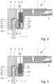
- the stabilizer 1 is described below in particular with reference to Figs. 2 and 3 explained in more detail.
- Figs. 2 and 3 a section of the stabilizer 1 is shown, where Fig. 2 shows a starting position of the stabilizer 1 and Fig. 3 shows a clamping position of the stabilizer 1.
- the disk 3 in particular can be arranged in the holder 4.
- Fig. 3 or the clamping position in particular the disk 3 is clamped or can be clamped in the holder 4.
- the holder 4 preferably has an at least substantially U-shaped receptacle 8 for the disk 3.
- the receptacle 8 is preferably designed as a separate component, but can also be formed by sections and / or surfaces of the holder 4, in particular the holding part 14 explained below.
- the disk 3 can preferably be arranged in the receptacle 8.
- the holder 4 or receptacle 8 is preferably designed to accommodate an edge 3A of the disk 3 and/or to hold the disk 3 on an edge 3A or near an edge 3A.
- the edge 3A is in particular an upper edge of the Disc 3, as in the Fig. 1 to 3 shown.
- An upper edge is in particular an edge that points upwards in the installed position.
- the receptacle 8 preferably has two longitudinal segments 9, 10 and a transverse segment 11.
- the longitudinal segments 9, 10 and the transverse segment 11 preferably each have or form a contact surface 9A, 10A, 11A for contact with the disk 3.
- the longitudinal segments 9, 10 or their contact surfaces 9A, 10A are preferably at least essentially vertically aligned and the transverse segment 11 or their contact surface 11A is preferably at least essentially horizontally aligned.
- the longitudinal segments 9, 10 are preferably arranged opposite one another.
- the transverse segment 11 is arranged transversely to and/or between the longitudinal segments 9, 10.
- the longitudinal segments 9, 10 are preferably connected to one another by means of the transverse segment 11.
- the longitudinal segments 9, 10 and the transverse segment 11 preferably at least essentially form a U-shape.
- the longitudinal segments 9, 10 or their contact surfaces 9A, 10A are preferably arranged at least substantially parallel to one another, particularly in the starting position.
- the transverse segment 11 or its contact surface 11A is preferably arranged at least essentially at right angles to the longitudinal segments 9, 10 or their contact surfaces 9A, 10A.
- the receptacle 8 preferably has a receiving space 8A or the receptacle 8 delimits or defines a receiving space 8A.
- the receiving space 8A is preferably formed between the longitudinal segments 9, 10 and the transverse segment 11 or their contact surfaces 9A, 10A, 11A or through them limited.
- the holder 4 preferably has a channel 12.
- the channel 12 is designed to accommodate a screw 13.
- a channel 12 in the sense of the present invention is in particular a space or free space into which the screw 13 can be inserted or screwed.
- the channel 12 or the free space forming the channel 12 is preferably limited or formed by the holder 4 or sections of the holder 4.
- the holder 4 has one or more wall sections which delimit the channel 12 or through which the channel 12 is formed.
- the channel 12 preferably has a longitudinal axis L or extends in particular along a longitudinal axis L.
- the longitudinal axis L preferably runs vertically. If a disk 3 is clamped in the stabilizer 1 or the holder 4 or the receptacle 8, the longitudinal axis L preferably runs at least essentially parallel to the disk 3.
- the channel 12 preferably extends laterally next to the receptacle 8. In particular, the channel 12 preferably extends at least substantially parallel to the receptacle 8. If a disk 3 is held in the holder 4 or receptacle 8, the channel 12 or its runs Longitudinal axis L preferably at least substantially parallel to the disk 3.
- the screw 13 in particular has a thread 13A.
- the stabilizer 1 preferably has the screw 13.
- the screw 13 is designed in particular as a threaded pin or grub screw. In other words, the screw 13 preferably has no screw head.
- the channel 12 preferably tapers, in particular along the longitudinal axis L and/or in the screw-in direction E. In other words, the diameter or cross section of the channel 12 decreases along the longitudinal axis L and/or in the screw-in direction E.
- the screw-in direction E is in the Figs. 2 and 3 represented by an arrow.
- the screwing direction E runs in particular along the longitudinal axis L and/or from top to bottom.
- the holder 4 is preferably designed so that the holder 4 or part of it is deformed by screwing the screw 13 into the channel 12.
- the deformation is such that a disc 3 can be clamped in the receptacle 8 or a disc 3 arranged in the receptacle 8 is clamped.
- the channel 12 preferably has a thread 12A.
- the thread 12A corresponds to the thread 13A of the screw 13 and/or the thread 13A of the screw 13 and the thread 12A of the channel 12 are designed to be complementary to one another.
- the thread 12A of the channel 12 is preferably not completely circumferential. In other words, only a part or section of the surfaces delimiting the channel 12 has the thread 12A or a thread section.
- the thread 12A is preferably helical or spiral-shaped.
- a helical or spiral-like thread 12 is arranged in particular on a cylindrical or conical base surface or is formed by threads on a cylindrical or conical base surface.
- the thread 12A can also be formed by grooves corresponding or complementary to the thread 13A and/or a toothed rack or the like.
- the grooves or the rack preferably form threads on an at least substantially flat base surface.
- the channel 12 is preferably conical, in particular tapered.
- the channel 12 is understood to mean in particular that the channel 12 or at least a section thereof corresponds at least essentially to a section of a cone.
- the channel 12 is already “conical” in the sense of the present disclosure if it only has a conical section.
- it is preferably not necessary for the channel 12 to be completely conical.
- the channel 12 is conical in that one or more sections of the holder 4, which delimits the channel 12 or through which the channel 12 is defined, in particular the thread segment 17 explained below and / or the counter surface 18 explained below, at least essentially have the shape of a conical surface.
- the channel 12 is preferably open at the top, as shown in particular in FIGS Figs. 2 and 3 is visible.
- the holder 4 is preferably designed in several parts, and therefore preferably consists of several separate components.
- the holder 4 has a holding part 14 and a clamping wedge 15.
- the clamping wedge 15 is a separate component from the holding part 14.
- the holding part 14 it is also possible for the holding part 14 to have or form the clamping wedge 14 or for the clamping wedge 15 to be formed in one piece with the holding part 14.
- the holding part 14 is in Fig. 4 shown in a perspective view.
- the Fig. 5 shows the clamping wedge 15 in a perspective view.
- the holding part 14 is preferably connected or connectable to the strut 6 via the joint 7.
- the clamping wedge 15 is designed in particular to hold or clamp the disk 3 in a clamping manner.
- the clamping wedge 15 can preferably be inserted into the holding part 14 or inserted therein.
- the holding part 14 in particular has a recess 16 for receiving the receptacle 8 and/or the clamping wedge 15.
- the clamping wedge 15 is held in a form-fitting manner in the holding part 14, in particular in the recess 16, or is held therein.
- the recess 16 is preferably arranged on an underside of the holding part 14 and/or is open at the bottom.
- the channel 12 and the recess 16 are open in opposite directions and/or arranged on opposite sides of the holding part 14 or the holder 4.
- the clamping wedge 15 is designed in particular to hold or clamp the disk 3 in a clamping manner.
- the clamping wedge 15 is preferably at least partially flexible and/or consists at least partially of a flexible material.
- the clamping wedge 15 is made of plastic.
- the clamping wedge 15 is preferably at least partially deformable.
- the clamping wedge 15 is deformable in such a way that it can be inserted into the recess 16 and/or that the disk 3 can be clamped by means of the clamping wedge 15 by screwing the screw 13 into the channel 12.
- the clamping wedge 15 is preferably elastic.
- the clamping wedge 15 is so elastic that it automatically returns to its original position or shape after insertion or introduction into the recess 16, so that it is held in a form-fitting manner in the holder 4 or recess 16, as in particular in Fig. 2 shown.
- the assembly of the stabilizer 1 or the holder 4 takes place in that the clamping wedge 15 is first deformed or compressed, then inserted into the recess 16 and then released, so that it moves back elastically to its starting position before the deformation and is therefore held in a form-fitting manner in the recess 16.
- the clamping wedge 15 has the receptacle 8 or the clamping wedge 15 forms the receptacle 8.
- the holding part 14 it is also possible for the holding part 14 to have or form the receptacle 8 or for the receptacle 8 to be formed in one piece with the holding part 14.
- the Fig. 2 shows the stabilizer 1 or the holder 4 with the clamping wedge 15 inserted into the holding part 14 or arranged in the holding part 14.
- the holder 4 or the clamping wedge 15 is shown in a starting position.
- the screw 13 in an entrance area of the channel 12.
- the channel 12 preferably tapers so that the channel 12 below the screw 13 has a smaller diameter than the screw 13.
- the clamping wedge 15 or the receptacle 8 deforming or being deformed by the screw 13.
- the long side 9 of the receptacle 8 is deformed or the long side 9 is pressed or deformed or pivoted in the direction of the opposite long side 10 of the receptacle 8.
- the receiving space 8A for the disk 3 formed by the receptacle 8 or enclosed by the receptacle 8 is reduced or the distance between the longitudinal segments 9, 10 the receptacle 8 or its contact surfaces 9A, 10A are reduced.
- the disk 3 can be clamped in the receptacle 8 or holder 4.
- the screw 13 is completely screwed into the channel 12.
- the disk 3 is clamped or held therein in a clamping manner in the receptacle 8 or holder 4.
- the in Fig. 3 The position shown in particular represents a clamping position of the stabilizer 1 or the holder 4.
- the receiving space 8A is reduced to the maximum or the distance between the longitudinal segments 9, 10 or their contact surfaces 9A, 10A is minimal and / or the holding force or clamping force exerted on the disk 3 is maximum.
- the holder 4 or the clamping wedge 15 preferably has a thread segment 17.
- the holding part 14 it would also be possible for the holding part 14 to have the thread segment 17 or for the thread segment 17 to be formed in one piece with the holding part 14.
- the thread segment 17 preferably has or forms the thread 12A of the channel 12 or at least a portion thereof.
- the thread segment 17 is preferably arranged or attached to the receptacle 8, in particular to one of the longitudinal segments 9, 10.
- the thread segment 17 is particularly preferably formed in one piece with the receptacle 8.
- the thread segment 17 is arranged on a side of the longitudinal segment 9 facing the longitudinal segment 10 and/or facing away from the contact surface 9A.
- the clamping wedge 15 is a one-piece component which has the receptacle 8 and the thread segment 17 or is formed thereby.
- the channel 12 is preferably formed between the clamping wedge 15 and a counter surface 18 opposite or assigned to the clamping wedge 15 or is at least essentially delimited by the clamping wedge 15 and the counter surface 18.
- the holding part 14 preferably has the counter surface 18 or the holding part 14 forms the counter surface 18.
- the channel 12 is preferably formed by two separate components, in the exemplary embodiment in particular by the clamping wedge 15 or its thread segment 17 on the one hand and by the holding part 14 or its counter surface 18 on the other hand.
- the counter surface 18 is preferably cylindrical or conical. Particularly preferably, the counter surface 18 runs obliquely to the longitudinal axis L of the channel 12 and/or the channel 12 is tapered, in particular conically, by the counter surface 18 in the screwing-in direction E.
- the counter surface 18 is an at least substantially smooth or flat surface. In particular, in the exemplary embodiment shown, the counter surface 18 has no thread.
- the counter surface 18 it is also possible for the counter surface 18 to have or form a threaded section.
- the thread 12A of the channel 12 can be formed by different sections, in particular the thread section of the thread segment 17 and a corresponding or supplementary thread section which is arranged on the counter surface 18.
- the stabilizer 1 and the disk 3 in particular form a system.
Applications Claiming Priority (1)
| Application Number | Priority Date | Filing Date | Title |
|---|---|---|---|
| DE202022101974.6U DE202022101974U1 (de) | 2022-04-12 | 2022-04-12 | Stabilisator zum Stabilisieren einer Scheibe |
Publications (1)
| Publication Number | Publication Date |
|---|---|
| EP4260775A1 true EP4260775A1 (fr) | 2023-10-18 |
Family
ID=82116224
Family Applications (1)
| Application Number | Title | Priority Date | Filing Date |
|---|---|---|---|
| EP23162241.6A Pending EP4260775A1 (fr) | 2022-04-12 | 2023-03-16 | Stabilisateur pour stabiliser une vitre |
Country Status (2)
| Country | Link |
|---|---|
| EP (1) | EP4260775A1 (fr) |
| DE (1) | DE202022101974U1 (fr) |
Citations (2)
| Publication number | Priority date | Publication date | Assignee | Title |
|---|---|---|---|---|
| DE202010011693U1 (de) | 2010-04-17 | 2011-02-10 | Reichel Kg Metallbau Und Kunstverarbeitung | Aussteifungsverstrebung zum Aussteifen von Dusch- und Raumabtrennungen mit Keil-Klemmung |
| IT201800002361A1 (it) * | 2018-02-02 | 2019-08-02 | Lacus S R L | Parete doccia con anta scorrevole. |
-
2022
- 2022-04-12 DE DE202022101974.6U patent/DE202022101974U1/de active Active
-
2023
- 2023-03-16 EP EP23162241.6A patent/EP4260775A1/fr active Pending
Patent Citations (2)
| Publication number | Priority date | Publication date | Assignee | Title |
|---|---|---|---|---|
| DE202010011693U1 (de) | 2010-04-17 | 2011-02-10 | Reichel Kg Metallbau Und Kunstverarbeitung | Aussteifungsverstrebung zum Aussteifen von Dusch- und Raumabtrennungen mit Keil-Klemmung |
| IT201800002361A1 (it) * | 2018-02-02 | 2019-08-02 | Lacus S R L | Parete doccia con anta scorrevole. |
Also Published As
| Publication number | Publication date |
|---|---|
| DE202022101974U1 (de) | 2022-06-03 |
Similar Documents
| Publication | Publication Date | Title |
|---|---|---|
| EP0761131B1 (fr) | Dispositif de fixation réglable pour assembler un panneau frontal au cadre de tiroir | |
| DE2723850A1 (de) | Moebelscharnier | |
| DE2614446A1 (de) | Scharnier | |
| DE102005000129A1 (de) | Befestigungsvorrichtung für die Befestigung von Solarpaneelen an einer Montageschiene | |
| DE202005010186U1 (de) | Halteeinrichtung sowie Halteelement hierfür | |
| AT10883U1 (de) | Befestigungsvorrichtung mit einer klemmvorrichtung | |
| DE7610443U1 (de) | Scharnier | |
| AT501658A2 (de) | Vorrichtung zum befestigen eines fensterrahmens mittels einer justierschraube | |
| EP1222406B1 (fr) | Element de retenue pour vis a tete | |
| DE102005045455B4 (de) | Befestigungseinrichtung für eine Möbelabstützung | |
| EP4260775A1 (fr) | Stabilisateur pour stabiliser une vitre | |
| EP2412883A1 (fr) | Appui ponctuel, notamment pour éléments de façade | |
| CH698877B1 (de) | Untergestell für eine Sanitärwanne. | |
| CH664678A5 (de) | Schubkastenauszug. | |
| EP0626522B1 (fr) | Cheville à bascule | |
| DE3611873A1 (de) | Befestigungselement zum verstellbaren befestigen von bauelementen an bauwerken | |
| DE3444994C2 (de) | Verstellbarer Scharnierarm | |
| DE202020103389U1 (de) | Anschlussvorrichtung zum Befestigen an einem Hohlprofil sowie Stabilisierungsset und Stabilisierungsanordnung | |
| EP2304147B1 (fr) | Dispositif de support pour une porte coulissante | |
| DE102006006727A1 (de) | Einrichtung, insbesondere Duschabtrennung oder Fassade, Beschlag und Scheibe | |
| DE19844324A1 (de) | Plattenhaltersystem | |
| CH632802A5 (de) | Vorrichtung zum befestigen eines tuerschliessers. | |
| DE102010049194A1 (de) | Justiersystem für Bauelemente | |
| DE202010015387U1 (de) | Justiersystem | |
| DE102005056850B3 (de) | Türband |
Legal Events
| Date | Code | Title | Description |
|---|---|---|---|
| PUAI | Public reference made under article 153(3) epc to a published international application that has entered the european phase |
Free format text: ORIGINAL CODE: 0009012 |
|
| STAA | Information on the status of an ep patent application or granted ep patent |
Free format text: STATUS: THE APPLICATION HAS BEEN PUBLISHED |
|
| AK | Designated contracting states |
Kind code of ref document: A1 Designated state(s): AL AT BE BG CH CY CZ DE DK EE ES FI FR GB GR HR HU IE IS IT LI LT LU LV MC ME MK MT NL NO PL PT RO RS SE SI SK SM TR |
|
| STAA | Information on the status of an ep patent application or granted ep patent |
Free format text: STATUS: REQUEST FOR EXAMINATION WAS MADE |