EP4260775A1 - Stabilizer for stabilizing a glass pane - Google Patents
Stabilizer for stabilizing a glass pane Download PDFInfo
- Publication number
- EP4260775A1 EP4260775A1 EP23162241.6A EP23162241A EP4260775A1 EP 4260775 A1 EP4260775 A1 EP 4260775A1 EP 23162241 A EP23162241 A EP 23162241A EP 4260775 A1 EP4260775 A1 EP 4260775A1
- Authority
- EP
- European Patent Office
- Prior art keywords
- stabilizer
- holder
- channel
- screw
- clamping wedge
- Prior art date
- Legal status (The legal status is an assumption and is not a legal conclusion. Google has not performed a legal analysis and makes no representation as to the accuracy of the status listed.)
- Pending
Links
- 239000003381 stabilizer Substances 0.000 title claims abstract description 78
- 230000000087 stabilizing effect Effects 0.000 title claims abstract description 5
- 239000011521 glass Substances 0.000 title description 8
- 238000005192 partition Methods 0.000 claims abstract description 11
- 239000000463 material Substances 0.000 claims description 6
- 230000000717 retained effect Effects 0.000 claims 1
- 230000000875 corresponding effect Effects 0.000 description 4
- 230000006378 damage Effects 0.000 description 3
- 238000009434 installation Methods 0.000 description 3
- 238000004519 manufacturing process Methods 0.000 description 3
- 230000000295 complement effect Effects 0.000 description 2
- 208000027418 Wounds and injury Diseases 0.000 description 1
- 230000006978 adaptation Effects 0.000 description 1
- 238000004026 adhesive bonding Methods 0.000 description 1
- 238000010276 construction Methods 0.000 description 1
- 230000007423 decrease Effects 0.000 description 1
- 238000011161 development Methods 0.000 description 1
- 230000018109 developmental process Effects 0.000 description 1
- 208000014674 injury Diseases 0.000 description 1
- 238000003780 insertion Methods 0.000 description 1
- 230000037431 insertion Effects 0.000 description 1
Images


Classifications
-
- A—HUMAN NECESSITIES
- A47—FURNITURE; DOMESTIC ARTICLES OR APPLIANCES; COFFEE MILLS; SPICE MILLS; SUCTION CLEANERS IN GENERAL
- A47K—SANITARY EQUIPMENT NOT OTHERWISE PROVIDED FOR; TOILET ACCESSORIES
- A47K3/00—Baths; Douches; Appurtenances therefor
- A47K3/28—Showers or bathing douches
- A47K3/30—Screens or collapsible cabinets for showers or baths
-
- F—MECHANICAL ENGINEERING; LIGHTING; HEATING; WEAPONS; BLASTING
- F16—ENGINEERING ELEMENTS AND UNITS; GENERAL MEASURES FOR PRODUCING AND MAINTAINING EFFECTIVE FUNCTIONING OF MACHINES OR INSTALLATIONS; THERMAL INSULATION IN GENERAL
- F16B—DEVICES FOR FASTENING OR SECURING CONSTRUCTIONAL ELEMENTS OR MACHINE PARTS TOGETHER, e.g. NAILS, BOLTS, CIRCLIPS, CLAMPS, CLIPS OR WEDGES; JOINTS OR JOINTING
- F16B9/00—Connections of rods or tubular parts to flat surfaces at an angle
- F16B9/05—Connections of rods or tubular parts to flat surfaces at an angle by way of an intermediate member
- F16B9/054—Connections of rods or tubular parts to flat surfaces at an angle by way of an intermediate member the intermediate member being threaded
-
- F—MECHANICAL ENGINEERING; LIGHTING; HEATING; WEAPONS; BLASTING
- F16—ENGINEERING ELEMENTS AND UNITS; GENERAL MEASURES FOR PRODUCING AND MAINTAINING EFFECTIVE FUNCTIONING OF MACHINES OR INSTALLATIONS; THERMAL INSULATION IN GENERAL
- F16B—DEVICES FOR FASTENING OR SECURING CONSTRUCTIONAL ELEMENTS OR MACHINE PARTS TOGETHER, e.g. NAILS, BOLTS, CIRCLIPS, CLAMPS, CLIPS OR WEDGES; JOINTS OR JOINTING
- F16B9/00—Connections of rods or tubular parts to flat surfaces at an angle
- F16B9/05—Connections of rods or tubular parts to flat surfaces at an angle by way of an intermediate member
- F16B9/058—Connections of rods or tubular parts to flat surfaces at an angle by way of an intermediate member the intermediate member being secured to the rod by transverse fasteners
Definitions
- the present invention relates to a stabilizer for stabilizing a pane, in particular a shower partition, according to the preamble of claim 1 and a system with a stabilizer and a pane.
- stabilizers for stabilizing a pane or a shower partition are known from the prior art.
- showers often have a glass pane as a shower partition, one long side of which is attached to a wall and possibly also one short side to the floor.
- a problem here can be that strong forces act on the fastening devices used due to the relatively high weight of the shower partition or glass pane and the only one-sided or possibly two-sided fastening and/or that the fastening is not sufficiently stable. This poses a risk of damage to the shower partition and/or injury to a user if damage occurs.
- stabilizers are sometimes used to additionally hold or stabilize the pane or shower partition.
- such a stabilizer is essentially rod-like and has one end attached to a wall. At the other end, the stabilizer usually has a holder for holding the disk, in particular on its upper edge.
- the DE 20 2010 011 693 U1 relates to a bracing system for mounting real glass panes or other material panels in wet and residential areas as well as outdoors.
- the bracing is provided on the wall side with a wall mounting plate that is firmly connected to the wall.
- a holder is placed on the edge of the glass and secured by screwing in a screw. This screw presses a wedge into the clamp holder holder over a corresponding slope and thus presses the glass against a counter surface made of non-slip material, which is shaped to protect sensitive materials in such a way that the edge is not damaged.
- a stabilizer according to the invention is used to stabilize a pane.
- the pane is in particular a shower partition.
- the stabilizer according to the invention has a holder for holding the pane in a particularly clamping manner and a wall fastening part for attaching the stabilizer to a wall. Furthermore, the holder of the stabilizer has an at least substantially U-shaped receptacle for the disc.
- the stabilizer or holder has a tapered channel with a thread for receiving a screw. This is conducive to a simple structure of the holder or the stabilizer as well as simple assembly.
- the holder has a clamping wedge for clamping the pane.
- the holder preferably has a holding part.
- the clamping wedge is preferably held or maintained in a form-fitting manner in the holding part. This simplifies the assembly of the stabilizer, since the clamping wedge can first be inserted into the holding part or arranged on it in such a way that the clamping wedge is held in a form-fitting manner and cannot fall out of the holding part on its own. The disc can then be arranged in the holder or receptacle and clamped there without the clamping wedge having to be additionally secured.
- the two-part design of the holder with the clamping wedge and the holding part simplifies the production of the stabilizer or the holder.
- the channel preferably extends laterally next to the receptacle and/or essentially parallel to the receptacle. This achieves a large-area distribution of the clamping force, so that the point loads on the disc and the holder are minimized. This also makes assembly easier.
- the channel is preferably open at the top. This makes mounting the stabilizer easier because the disc extends essentially downwards and upwards from the holder side, so that the screw can simply be screwed into the channel from above without disturbing the washer or getting in the way.
- the holder is preferably designed so that the holder or a part thereof is deformed by screwing the screw into the channel, in particular in such a way that a disk arranged in the receptacle is clamped. In this way, a clamping hold of the pane in the holder can be achieved in a simple manner. This makes assembly easier.
- the clamping wedge preferably consists of a flexible material, in particular plastic.
- the clamping wedge is designed to deform when the screw is screwed into the channel and/or to clamp a disk arranged in the receptacle. This is conducive to easy assembly.
- the clamping wedge has or forms the U-shaped receptacle.
- the U-shaped receptacle in particular has or is formed by two opposing longitudinal segments and a transverse segment arranged between them.
- the clamping wedge preferably has a thread segment which has or forms the thread or at least a section thereof. This is conducive to simple construction and assembly.
- the thread segment is preferably arranged on one of the longitudinal segments and/or formed in one piece with it. This reduces the number of individual parts and thus simplifies production and assembly.
- the thread segment or its thread is preferably conical. This ensures a good hold of the screw in the thread and a stronger clamping of the washer as the screw is increasingly screwed into the channel. This allows for easy adjustment of the clamping force with which the disc is clamped.
- the channel is preferably formed between the clamping wedge and a counter surface opposite and/or assigned to the clamping wedge. This results in a simple structure.
- the counter surface preferably runs obliquely to a longitudinal axis of the channel. This makes the channel narrower in a simple way.
- the counter surface can have a threaded section and thus, in particular, form a thread together with the clamping wedge. However, this is not mandatory.
- the stabilizer preferably has the screw.
- the screw is designed as a grub screw. This enables the holder to be constructed in a space-saving manner, as no free space has to be provided for a screw head.
- a screw designed as a grub screw can be screwed completely into the channel so that it is not visible from the outside.
- the present invention also relates to a system with a stabilizer and a disk, the stabilizer being designed as described above and/or explained in more detail below.
- Fig. 1 shows a schematic perspective view of a proposed stabilizer 1.
- the stabilizer 1 is attached to a wall 2 and a disk 3 is held with the stabilizer 1 or a holder 3 of the stabilizer 1 or clamped therein.
- the stabilizer 1 is in the Fig. 1 So assembled or shown in its installation position.
- the term “installation position” of the stabilizer 1 or a part thereof refers to the intended orientation or positioning of the stabilizer 1 or part in the assembled or installed state, as in particular in Fig. 1 shown.
- the pane 3 is in particular a shower partition.
- the pane 3 is preferably designed as a particularly transparent and/or translucent pane, for example as a glass pane or plastic pane.
- a shower partition is in particular a panel or wall that separates a shower room from another room or divides a room, such as a bathroom, into a shower room and another area.
- the stabilizer 1 is designed in particular to hold or stabilize the disk 3.
- the stabilizer 1 has a holder 4 and a wall fastening part 5.
- the holder 4 is designed to hold the disk 3.
- the holder 4 is designed to hold the disk 3 in a clamping manner.
- the wall fastening part 5 is designed to fasten the stabilizer 1 to the wall 2.
- the wall fastening part 5 can preferably be fastened or attached to the wall 2 by means of gluing or screwing.
- the stabilizer 1 has a strut 6, which is arranged or can be arranged on or between the holder 4 and the wall fastening part 5 and is attached or attachable to these.
- the stabilizer 1 and/or the strut 6 is/are preferably at least substantially elongated and/or rod-like.
- the strut 6 preferably has a hollow profile or is formed thereby.
- the strut 6 can preferably be screwed to the holder 4 and/or the wall fastening part 5 by screwing.
- other solutions are also possible here.
- the strut 6 is connected or connectable to the holder 4 and/or the wall fastening part 5 via a joint 7.
- the strut 6 is - particularly in the unassembled state or before assembly - preferably pivotable relative to the holder 4 and / or the wall fastening part 5.
- This enables, in particular, a non-rectangular arrangement of the stabilizer 1 or the strut 6 relative to the wall 2 and/or the disk 3.
- the strut 6 or the stabilizer 1 can therefore be arranged obliquely to the wall 2 and/or disk 3 . can be attached to it. This enables flexible use of the stabilizer 1 or a simple adaptation of the stabilizer 1 to different local installation conditions.
- the stabilizer 1 is described below in particular with reference to Figs. 2 and 3 explained in more detail.
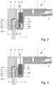
- Figs. 2 and 3 a section of the stabilizer 1 is shown, where Fig. 2 shows a starting position of the stabilizer 1 and Fig. 3 shows a clamping position of the stabilizer 1.
- the disk 3 in particular can be arranged in the holder 4.
- Fig. 3 or the clamping position in particular the disk 3 is clamped or can be clamped in the holder 4.
- the holder 4 preferably has an at least substantially U-shaped receptacle 8 for the disk 3.
- the receptacle 8 is preferably designed as a separate component, but can also be formed by sections and / or surfaces of the holder 4, in particular the holding part 14 explained below.
- the disk 3 can preferably be arranged in the receptacle 8.
- the holder 4 or receptacle 8 is preferably designed to accommodate an edge 3A of the disk 3 and/or to hold the disk 3 on an edge 3A or near an edge 3A.
- the edge 3A is in particular an upper edge of the Disc 3, as in the Fig. 1 to 3 shown.
- An upper edge is in particular an edge that points upwards in the installed position.
- the receptacle 8 preferably has two longitudinal segments 9, 10 and a transverse segment 11.
- the longitudinal segments 9, 10 and the transverse segment 11 preferably each have or form a contact surface 9A, 10A, 11A for contact with the disk 3.
- the longitudinal segments 9, 10 or their contact surfaces 9A, 10A are preferably at least essentially vertically aligned and the transverse segment 11 or their contact surface 11A is preferably at least essentially horizontally aligned.
- the longitudinal segments 9, 10 are preferably arranged opposite one another.
- the transverse segment 11 is arranged transversely to and/or between the longitudinal segments 9, 10.
- the longitudinal segments 9, 10 are preferably connected to one another by means of the transverse segment 11.
- the longitudinal segments 9, 10 and the transverse segment 11 preferably at least essentially form a U-shape.
- the longitudinal segments 9, 10 or their contact surfaces 9A, 10A are preferably arranged at least substantially parallel to one another, particularly in the starting position.
- the transverse segment 11 or its contact surface 11A is preferably arranged at least essentially at right angles to the longitudinal segments 9, 10 or their contact surfaces 9A, 10A.
- the receptacle 8 preferably has a receiving space 8A or the receptacle 8 delimits or defines a receiving space 8A.
- the receiving space 8A is preferably formed between the longitudinal segments 9, 10 and the transverse segment 11 or their contact surfaces 9A, 10A, 11A or through them limited.
- the holder 4 preferably has a channel 12.
- the channel 12 is designed to accommodate a screw 13.
- a channel 12 in the sense of the present invention is in particular a space or free space into which the screw 13 can be inserted or screwed.
- the channel 12 or the free space forming the channel 12 is preferably limited or formed by the holder 4 or sections of the holder 4.
- the holder 4 has one or more wall sections which delimit the channel 12 or through which the channel 12 is formed.
- the channel 12 preferably has a longitudinal axis L or extends in particular along a longitudinal axis L.
- the longitudinal axis L preferably runs vertically. If a disk 3 is clamped in the stabilizer 1 or the holder 4 or the receptacle 8, the longitudinal axis L preferably runs at least essentially parallel to the disk 3.
- the channel 12 preferably extends laterally next to the receptacle 8. In particular, the channel 12 preferably extends at least substantially parallel to the receptacle 8. If a disk 3 is held in the holder 4 or receptacle 8, the channel 12 or its runs Longitudinal axis L preferably at least substantially parallel to the disk 3.
- the screw 13 in particular has a thread 13A.
- the stabilizer 1 preferably has the screw 13.
- the screw 13 is designed in particular as a threaded pin or grub screw. In other words, the screw 13 preferably has no screw head.
- the channel 12 preferably tapers, in particular along the longitudinal axis L and/or in the screw-in direction E. In other words, the diameter or cross section of the channel 12 decreases along the longitudinal axis L and/or in the screw-in direction E.
- the screw-in direction E is in the Figs. 2 and 3 represented by an arrow.
- the screwing direction E runs in particular along the longitudinal axis L and/or from top to bottom.
- the holder 4 is preferably designed so that the holder 4 or part of it is deformed by screwing the screw 13 into the channel 12.
- the deformation is such that a disc 3 can be clamped in the receptacle 8 or a disc 3 arranged in the receptacle 8 is clamped.
- the channel 12 preferably has a thread 12A.
- the thread 12A corresponds to the thread 13A of the screw 13 and/or the thread 13A of the screw 13 and the thread 12A of the channel 12 are designed to be complementary to one another.
- the thread 12A of the channel 12 is preferably not completely circumferential. In other words, only a part or section of the surfaces delimiting the channel 12 has the thread 12A or a thread section.
- the thread 12A is preferably helical or spiral-shaped.
- a helical or spiral-like thread 12 is arranged in particular on a cylindrical or conical base surface or is formed by threads on a cylindrical or conical base surface.
- the thread 12A can also be formed by grooves corresponding or complementary to the thread 13A and/or a toothed rack or the like.
- the grooves or the rack preferably form threads on an at least substantially flat base surface.
- the channel 12 is preferably conical, in particular tapered.
- the channel 12 is understood to mean in particular that the channel 12 or at least a section thereof corresponds at least essentially to a section of a cone.
- the channel 12 is already “conical” in the sense of the present disclosure if it only has a conical section.
- it is preferably not necessary for the channel 12 to be completely conical.
- the channel 12 is conical in that one or more sections of the holder 4, which delimits the channel 12 or through which the channel 12 is defined, in particular the thread segment 17 explained below and / or the counter surface 18 explained below, at least essentially have the shape of a conical surface.
- the channel 12 is preferably open at the top, as shown in particular in FIGS Figs. 2 and 3 is visible.
- the holder 4 is preferably designed in several parts, and therefore preferably consists of several separate components.
- the holder 4 has a holding part 14 and a clamping wedge 15.
- the clamping wedge 15 is a separate component from the holding part 14.
- the holding part 14 it is also possible for the holding part 14 to have or form the clamping wedge 14 or for the clamping wedge 15 to be formed in one piece with the holding part 14.
- the holding part 14 is in Fig. 4 shown in a perspective view.
- the Fig. 5 shows the clamping wedge 15 in a perspective view.
- the holding part 14 is preferably connected or connectable to the strut 6 via the joint 7.
- the clamping wedge 15 is designed in particular to hold or clamp the disk 3 in a clamping manner.
- the clamping wedge 15 can preferably be inserted into the holding part 14 or inserted therein.
- the holding part 14 in particular has a recess 16 for receiving the receptacle 8 and/or the clamping wedge 15.
- the clamping wedge 15 is held in a form-fitting manner in the holding part 14, in particular in the recess 16, or is held therein.
- the recess 16 is preferably arranged on an underside of the holding part 14 and/or is open at the bottom.
- the channel 12 and the recess 16 are open in opposite directions and/or arranged on opposite sides of the holding part 14 or the holder 4.
- the clamping wedge 15 is designed in particular to hold or clamp the disk 3 in a clamping manner.
- the clamping wedge 15 is preferably at least partially flexible and/or consists at least partially of a flexible material.
- the clamping wedge 15 is made of plastic.
- the clamping wedge 15 is preferably at least partially deformable.
- the clamping wedge 15 is deformable in such a way that it can be inserted into the recess 16 and/or that the disk 3 can be clamped by means of the clamping wedge 15 by screwing the screw 13 into the channel 12.
- the clamping wedge 15 is preferably elastic.
- the clamping wedge 15 is so elastic that it automatically returns to its original position or shape after insertion or introduction into the recess 16, so that it is held in a form-fitting manner in the holder 4 or recess 16, as in particular in Fig. 2 shown.
- the assembly of the stabilizer 1 or the holder 4 takes place in that the clamping wedge 15 is first deformed or compressed, then inserted into the recess 16 and then released, so that it moves back elastically to its starting position before the deformation and is therefore held in a form-fitting manner in the recess 16.
- the clamping wedge 15 has the receptacle 8 or the clamping wedge 15 forms the receptacle 8.
- the holding part 14 it is also possible for the holding part 14 to have or form the receptacle 8 or for the receptacle 8 to be formed in one piece with the holding part 14.
- the Fig. 2 shows the stabilizer 1 or the holder 4 with the clamping wedge 15 inserted into the holding part 14 or arranged in the holding part 14.
- the holder 4 or the clamping wedge 15 is shown in a starting position.
- the screw 13 in an entrance area of the channel 12.
- the channel 12 preferably tapers so that the channel 12 below the screw 13 has a smaller diameter than the screw 13.
- the clamping wedge 15 or the receptacle 8 deforming or being deformed by the screw 13.
- the long side 9 of the receptacle 8 is deformed or the long side 9 is pressed or deformed or pivoted in the direction of the opposite long side 10 of the receptacle 8.
- the receiving space 8A for the disk 3 formed by the receptacle 8 or enclosed by the receptacle 8 is reduced or the distance between the longitudinal segments 9, 10 the receptacle 8 or its contact surfaces 9A, 10A are reduced.
- the disk 3 can be clamped in the receptacle 8 or holder 4.
- the screw 13 is completely screwed into the channel 12.
- the disk 3 is clamped or held therein in a clamping manner in the receptacle 8 or holder 4.
- the in Fig. 3 The position shown in particular represents a clamping position of the stabilizer 1 or the holder 4.
- the receiving space 8A is reduced to the maximum or the distance between the longitudinal segments 9, 10 or their contact surfaces 9A, 10A is minimal and / or the holding force or clamping force exerted on the disk 3 is maximum.
- the holder 4 or the clamping wedge 15 preferably has a thread segment 17.
- the holding part 14 it would also be possible for the holding part 14 to have the thread segment 17 or for the thread segment 17 to be formed in one piece with the holding part 14.
- the thread segment 17 preferably has or forms the thread 12A of the channel 12 or at least a portion thereof.
- the thread segment 17 is preferably arranged or attached to the receptacle 8, in particular to one of the longitudinal segments 9, 10.
- the thread segment 17 is particularly preferably formed in one piece with the receptacle 8.
- the thread segment 17 is arranged on a side of the longitudinal segment 9 facing the longitudinal segment 10 and/or facing away from the contact surface 9A.
- the clamping wedge 15 is a one-piece component which has the receptacle 8 and the thread segment 17 or is formed thereby.
- the channel 12 is preferably formed between the clamping wedge 15 and a counter surface 18 opposite or assigned to the clamping wedge 15 or is at least essentially delimited by the clamping wedge 15 and the counter surface 18.
- the holding part 14 preferably has the counter surface 18 or the holding part 14 forms the counter surface 18.
- the channel 12 is preferably formed by two separate components, in the exemplary embodiment in particular by the clamping wedge 15 or its thread segment 17 on the one hand and by the holding part 14 or its counter surface 18 on the other hand.
- the counter surface 18 is preferably cylindrical or conical. Particularly preferably, the counter surface 18 runs obliquely to the longitudinal axis L of the channel 12 and/or the channel 12 is tapered, in particular conically, by the counter surface 18 in the screwing-in direction E.
- the counter surface 18 is an at least substantially smooth or flat surface. In particular, in the exemplary embodiment shown, the counter surface 18 has no thread.
- the counter surface 18 it is also possible for the counter surface 18 to have or form a threaded section.
- the thread 12A of the channel 12 can be formed by different sections, in particular the thread section of the thread segment 17 and a corresponding or supplementary thread section which is arranged on the counter surface 18.
- the stabilizer 1 and the disk 3 in particular form a system.
Abstract
Die Erfindung betrifft einen Stabilisator zum Stabilisieren einer Scheibe, insbesondere einer Duschtrennwand, wobei der Stabilisator (1) eine Halterung (4) zum insbesondere klemmenden Halten der Scheibe (3) und ein Wandbefestigungsteil (5) zum Befestigen des Stabilisators (1) an einer Wand (2) aufweist, und wobei die Halterung (4) eine zumindest im Wesentlichen U-förmige Aufnahme (8) für die Scheibe (3) aufweist.Gemäß einem ersten Aspekt weist die Halterung (4) einen sich verjüngenden Kanal (12) mit einem Gewinde (12A) zur Aufnahme (8) einer Schraube (13) auf.Gemäß einem weiteren Aspekt weist die Halterung (4) ein Halteteil (14) und einen formschlüssig in dem Halteteil (14) gehaltenen oder haltbaren Klemmkeil (15) zum klemmenden Halten der Scheibe (3) auf.The invention relates to a stabilizer for stabilizing a pane, in particular a shower partition, wherein the stabilizer (1) has a holder (4) for holding the pane (3) in a particularly clamping manner and a wall fastening part (5) for attaching the stabilizer (1) to a wall (2), and wherein the holder (4) has an at least substantially U-shaped receptacle (8) for the disk (3). According to a first aspect, the holder (4) has a tapered channel (12) with a Thread (12A) for receiving (8) a screw (13). According to a further aspect, the holder (4) has a holding part (14) and a clamping wedge (15) which is held or held in a form-fitting manner in the holding part (14) for clamping holding the disc (3).
Description
Die vorliegende Erfindung betrifft einen Stabilisator zum Stabilisieren einer Scheibe, insbesondere einer Duschtrennwand, nach dem Oberbegriff des Anspruchs 1 sowie ein System mit einem Stabilisator und einer Scheibe.The present invention relates to a stabilizer for stabilizing a pane, in particular a shower partition, according to the preamble of
Grundsätzlich sind Stabilisatoren zum Stabilisieren einer Scheibe bzw. einer Duschtrennwand aus dem Stand der Technik bekannt.Basically, stabilizers for stabilizing a pane or a shower partition are known from the prior art.
Duschen weisen häufig als Duschtrennwand eine Glasscheibe auf, die mit einer Längsseite an einer Wand und ggf. auch mit einer Querseite am Boden befestigt ist. Hierbei kann ein Problem darin bestehen, dass durch das verhältnismäßig hohe Gewicht der Duschtrennwand bzw. Glasscheibe und die nur einseitige oder ggf. zweiseitige Befestigung starke Kräfte auf die verwendeten Befestigungseinrichtungen wirken und/oder dass die Befestigung nicht ausreichend stabil ist. Dies birgt die Gefahr von Beschädigungen der Duschtrennwand und/oder Verletzungen eines Benutzers bei einem auftretenden Schaden. Zur Stabilisierung bzw. Entlastung werden daher teilweise Stabilisatoren eingesetzt, die die Scheibe bzw. Duschtrennwand zusätzlich halten bzw. stabilisieren. Üblicherweise ist ein solcher Stabilisator im Wesentlichen stangenartig ausgebildet und mit einem Ende an einer Wand befestigt. An dem anderen Ende weist der Stabilisator üblicherweise eine Halterung zum Halten der Scheibe, insbesondere an deren Oberkante, auf.Showers often have a glass pane as a shower partition, one long side of which is attached to a wall and possibly also one short side to the floor. A problem here can be that strong forces act on the fastening devices used due to the relatively high weight of the shower partition or glass pane and the only one-sided or possibly two-sided fastening and/or that the fastening is not sufficiently stable. This poses a risk of damage to the shower partition and/or injury to a user if damage occurs. To stabilize or relieve the load, stabilizers are sometimes used to additionally hold or stabilize the pane or shower partition. Typically, such a stabilizer is essentially rod-like and has one end attached to a wall. At the other end, the stabilizer usually has a holder for holding the disk, in particular on its upper edge.
Die
Es ist eine Aufgabe der vorliegenden Erfindung, einen Stabilisator anzugeben, der eine einfache Montage ermöglicht und/oder einen möglichst einfachen Aufbau aufweist und/oder einfach und/oder kostengünstig herzustellen ist.It is an object of the present invention to provide a stabilizer that enables simple assembly and/or has the simplest possible structure and/or is simple and/or inexpensive to manufacture.
Die obige Aufgabe wird gelöst durch einen Stabilisator gemäß Anspruch 1. Vorteilhafte Weiterbildungen sind Gegenstand der Unteransprüche.The above task is solved by a stabilizer according to
Ein erfindungsgemäßer Stabilisator dient zum Stabilisieren einer Scheibe. Die Scheibe ist insbesondere eine Duschtrennwand.A stabilizer according to the invention is used to stabilize a pane. The pane is in particular a shower partition.
Der erfindungsgemäße Stabilisator weist eine Halterung zum insbesondere klemmenden Halten der Scheibe sowie ein Wandbefestigungsteil zum Befestigen des Stabilisators an einer Wand auf. Ferner weist die Halterung des Stabilisators eine zumindest im Wesentlichen U-förmige Aufnahme für die Scheibe auf.The stabilizer according to the invention has a holder for holding the pane in a particularly clamping manner and a wall fastening part for attaching the stabilizer to a wall. Furthermore, the holder of the stabilizer has an at least substantially U-shaped receptacle for the disc.
Gemäß einem ersten Aspekt der vorliegenden Erfindung weist der Stabilisator bzw. die Halterung einen sich verjüngenden Kanal mit einem Gewinde zur Aufnahme einer Schraube auf. Dies ist einem einfachen Aufbau der Halterung bzw. des Stabilisators sowie einer einfachen Montage zuträglich.According to a first aspect of the present invention, the stabilizer or holder has a tapered channel with a thread for receiving a screw. This is conducive to a simple structure of the holder or the stabilizer as well as simple assembly.
Gemäß einem weiteren, auch unabhängig realisierbaren Aspekt weist die Halterung einen Klemmkeil zum klemmenden Halten der Scheibe auf. Ferner weist die Halterung vorzugsweise ein Halteteil auf. Der Klemmkeil ist vorzugsweise formschlüssig in dem Halteteil gehalten oder haltbar. Hierdurch wird die Montage des Stabilisators vereinfacht, da der Klemmkeil zunächst derart in das Halteteil eingesetzt bzw. daran angeordnet werden kann, dass der Klemmkeil formschlüssig gehalten ist und nicht von alleine aus dem Halteteil herausfallen kann. Somit kann anschließend die Scheibe in der Halterung bzw. Aufnahme angeordnet werden und dort eingeklemmt werden, ohne dass hierbei zusätzlich noch der Klemmkeil gesichert werden muss. Andererseits wird durch die zweiteilige Ausführung der Halterung mit dem Klemmkeil und dem Halteteil die Herstellung des Stabilisators bzw. der Halterung vereinfacht.According to a further aspect that can also be implemented independently, the holder has a clamping wedge for clamping the pane. Furthermore, the holder preferably has a holding part. The clamping wedge is preferably held or maintained in a form-fitting manner in the holding part. This simplifies the assembly of the stabilizer, since the clamping wedge can first be inserted into the holding part or arranged on it in such a way that the clamping wedge is held in a form-fitting manner and cannot fall out of the holding part on its own. The disc can then be arranged in the holder or receptacle and clamped there without the clamping wedge having to be additionally secured. On the other hand, the two-part design of the holder with the clamping wedge and the holding part simplifies the production of the stabilizer or the holder.
Der Kanal erstreckt sich vorzugsweise seitlich neben der Aufnahme und/oder im Wesentlichen parallel zur Aufnahme. Hierdurch wird eine großflächige Verteilung der Klemmkraft erreicht, sodass die punktuellen Belastungen für die Scheibe und die Halterung minimiert werden. Zudem wird hierdurch die Montage erleichtert.The channel preferably extends laterally next to the receptacle and/or essentially parallel to the receptacle. This achieves a large-area distribution of the clamping force, so that the point loads on the disc and the holder are minimized. This also makes assembly easier.
Der Kanal ist in einer üblichen Gebrauchslage des Stabilisators vorzugsweise nach oben offen. Hierdurch wird die Montage des Stabilisators erleichtert, denn die Scheibe erstreckt sich von der Halterung aus im Wesentlichen nach unten und zur Seite, sodass die Schraube einfach von oben in den Kanal eingeschraubt werden kann, ohne dass hierbei die Scheibe stört bzw. im Weg ist.In a normal position of use of the stabilizer, the channel is preferably open at the top. This makes mounting the stabilizer easier because the disc extends essentially downwards and upwards from the holder side, so that the screw can simply be screwed into the channel from above without disturbing the washer or getting in the way.
Die Halterung ist vorzugsweise dazu ausgebildet, dass sich durch Einschrauben der Schraube in den Kanal die Halterung oder ein Teil davon verformt, insbesondere derart, dass eine in der Aufnahme angeordnete Scheibe eingeklemmt wird. Hierdurch kann auf einfache Weise ein klemmendes Halten der Scheibe in der Halterung erreicht werden. Es wird also die Montage erleichtert.The holder is preferably designed so that the holder or a part thereof is deformed by screwing the screw into the channel, in particular in such a way that a disk arranged in the receptacle is clamped. In this way, a clamping hold of the pane in the holder can be achieved in a simple manner. This makes assembly easier.
Der Klemmkeil besteht vorzugsweise aus einem flexiblen Material, insbesondere Kunststoff. Insbesondere ist der Klemmkeil dazu ausgebildet, sich beim Einschrauben der Schraube in den Kanal zu verformen und/oder eine in der Aufnahme angeordnete Scheibe einzuklemmen. Dies ist einer einfachen Montage zuträglich.The clamping wedge preferably consists of a flexible material, in particular plastic. In particular, the clamping wedge is designed to deform when the screw is screwed into the channel and/or to clamp a disk arranged in the receptacle. This is conducive to easy assembly.
Es ist bevorzugt, dass der Klemmkeil die U-förmige Aufnahme aufweist oder bildet. Die U-förmige Aufnahme weist insbesondere zwei sich gegenüberliegende Längssegmente und ein dazwischen angeordnetes Quersegment auf oder ist dadurch gebildet. Vorzugsweise weist der Klemmkeil ein Gewindesegment auf, welches das Gewinde oder zumindest einen Abschnitt davon aufweist oder bildet. Dies ist einem einfachen Aufbau und einer einfachen Montage zuträglich.It is preferred that the clamping wedge has or forms the U-shaped receptacle. The U-shaped receptacle in particular has or is formed by two opposing longitudinal segments and a transverse segment arranged between them. The clamping wedge preferably has a thread segment which has or forms the thread or at least a section thereof. This is conducive to simple construction and assembly.
Das Gewindesegment ist vorzugsweise an einem der Längssegmente angeordnet und/oder einstückig damit ausgebildet. Hierdurch wir die Anzahl der einzelnen Teile verringert und somit die Herstellung und Montage vereinfacht.The thread segment is preferably arranged on one of the longitudinal segments and/or formed in one piece with it. This reduces the number of individual parts and thus simplifies production and assembly.
Vorzugsweise ist das Gewindesegment bzw. dessen Gewinde konisch ausgebildet. Hierdurch werden ein guter Halt der Schraube in dem Gewinde und ein stärkeres Einklemmen der Scheibe bei zunehmendem Einschrauben der Schraube in den Kanal erreicht. Dies ermöglicht eine einfache Einstellung der Klemmkraft, mit der die Scheibe eingeklemmt wird.The thread segment or its thread is preferably conical. This ensures a good hold of the screw in the thread and a stronger clamping of the washer as the screw is increasingly screwed into the channel. This allows for easy adjustment of the clamping force with which the disc is clamped.
Der Kanal ist vorzugsweise zwischen dem Klemmkeil und einer dem Klemmkeil gegenüberliegenden und/oder zugeordneten Gegenfläche gebildet. Hierdurch wird ein einfacher Aufbau erreicht.The channel is preferably formed between the clamping wedge and a counter surface opposite and/or assigned to the clamping wedge. This results in a simple structure.
Die Gegenfläche verläuft vorzugsweise schräg zu einer Längsachse des Kanals. Hierdurch wird auf einfache Weise die Verjüngung des Kanals realisiert.The counter surface preferably runs obliquely to a longitudinal axis of the channel. This makes the channel narrower in a simple way.
Die Gegenfläche kann einen Gewindeabschnitt aufweisen und somit insbesondere gemeinsam mit dem Klemmkeil ein Gewinde bilden. Dies ist jedoch nicht zwingend.The counter surface can have a threaded section and thus, in particular, form a thread together with the clamping wedge. However, this is not mandatory.
Der Stabilisator weist vorzugsweise die Schraube auf. Insbesondere ist die Schraube als Madenschraube ausgebildet. Dies ermöglicht einen platzsparenden Aufbau der Halterung, da keine Freiräume für einen Schraubenkopf vorgesehen werden müssen. Außerdem kann eine als Madenschraube ausgebildete Schraube vollständig in den Kanal eingeschraubt werden, sodass sie von außen nicht sichtbar ist.The stabilizer preferably has the screw. In particular, the screw is designed as a grub screw. This enables the holder to be constructed in a space-saving manner, as no free space has to be provided for a screw head. In addition, a screw designed as a grub screw can be screwed completely into the channel so that it is not visible from the outside.
Gemäß einem weiteren Aspekt betrifft die vorliegende Erfindung auch ein System mit einem Stabilisator und einer Scheibe, wobei der Stabilisator wie voranstehend beschrieben und/oder nachfolgend näher erläutert ausgebildet ist.According to a further aspect, the present invention also relates to a system with a stabilizer and a disk, the stabilizer being designed as described above and/or explained in more detail below.
Die vorgenannten Aspekte und Merkmale der vorliegenden Erfindung sowie die sich aus der weiteren Beschreibung ergebenden Aspekte und Merkmale der vorliegenden Erfindung können unabhängig voneinander, aber auch in beliebiger Kombination realisiert werden.The aforementioned aspects and features of the present invention as well as the aspects and features of the present invention resulting from the further description can be implemented independently of one another, but also in any combination.
Weitere Vorteile, Merkmale, Eigenschaften und Aspekte der vorliegenden Erfindung ergeben sich aus den Ansprüchen und der folgenden Beschreibung einer bevorzugten Ausführungsform anhand der Zeichnung. Es zeigt:
- Fig. 1
- eine perspektivische Darstellung eines Stabilisators;
- Fig. 2
- einen ersten Schnitt durch den Stabilisator, wobei eine Halterung in einer Ausgangsposition dargestellt ist;
- Fig. 3
- einen zweiten Schnitt durch den Stabilisator, wobei die Halterung in einer Klemmposition dargestellt ist;
- Fig. 4
- eine perspektivische Darstellung eines Halteteils des Stabilisators; und
- Fig. 5
- eine perspektivische Darstellung eines Klemmkeils des Stabilisators.
- Fig. 1
- a perspective view of a stabilizer;
- Fig. 2
- a first section through the stabilizer, showing a bracket in a starting position;
- Fig. 3
- a second section through the stabilizer, with the bracket shown in a clamping position;
- Fig. 4
- a perspective view of a holding part of the stabilizer; and
- Fig. 5
- a perspective view of a clamping wedge of the stabilizer.
In den Figuren werden für gleiche oder ähnliche Teile dieselben Bezugszeichen verwendet, wobei entsprechende Eigenschaften und Vorteile erreicht werden können, auch wenn eine wiederholte Beschreibung aus Vereinfachungsgründen weggelassen ist.In the figures, the same reference numbers are used for the same or similar parts, whereby corresponding properties and advantages can be achieved, although repeated description is omitted for simplicity.
In der folgenden und der vorhergehenden Beschreibung benutzte Begriffe, die sich auf absolute Positionen oder Orientierungen im Raum beziehen, wie oben, unten, horizontal, vertikal u. dgl., beziehen sich vorzugsweise auf den montierten Stabilisator 1, selbst wenn dies nicht explizit erwähnt wird. Insbesondere bezeichnet der Begriff "Einbaulage" des Stabilisators 1 bzw. eines Teils davon die vorgesehene Orientierung bzw. Positionierung des Stabilisators 1 bzw. Teils im montierten bzw. eingebauten Zustand, wie insbesondere in
Die Scheibe 3 ist insbesondere eine Duschtrennwand. Vorzugsweise ist die Scheibe 3 als insbesondere durchsichtige und/oder lichtdurchlässige Scheibe, beispielsweise als Glasscheibe oder Kunststoffscheibe, ausgebildet.The
Eine Duschtrennwand ist insbesondere eine Scheibe oder Wand, die einen Duschraum von einem anderen Raum abtrennt bzw. einen Raum, wie beispielsweise ein Badezimmer, in einen Duschraum und einen anderen Bereich unterteilt.A shower partition is in particular a panel or wall that separates a shower room from another room or divides a room, such as a bathroom, into a shower room and another area.
Der Stabilisator 1 ist insbesondere zum Halten bzw. Stabilisieren der Scheibe 3 ausgebildet.The
Der Stabilisator 1 weist eine Halterung 4 und ein Wandbefestigungsteil 5 auf.The
Die Halterung 4 ist dazu ausgebildet, die Scheibe 3 zu halten. Insbesondere ist die Halterung 4 zum klemmenden Halten der Scheibe 3 ausgebildet.The
Das Wandbefestigungsteil 5 ist zum Befestigen des Stabilisators 1 an der Wand 2 ausgebildet. Das Wandbefestigungsteil 5 ist vorzugsweise mittels Verkleben oder Verschrauben an der Wand 2 befestigbar bzw. befestigt.The
Vorzugsweise weist der Stabilisator 1 eine Strebe 6 auf, die an bzw. zwischen der Halterung 4 und dem Wandbefestigungsteil 5 angeordnet bzw. anordenbar und an diesen befestigt bzw. befestigbar ist.Preferably, the
Der Stabilisator 1 und/oder die Strebe 6 ist/sind vorzugsweise zumindest im Wesentlichen länglich und/oder stangenartig ausgebildet. Vorzugsweise weist die Strebe 6 ein Hohlprofil auf oder ist hierdurch gebildet. Die Strebe 6 ist vorzugsweise durch Verschrauben mit der Haltung 4 und/oder dem Wandbefestigungsteil 5 verschraubbar. Hier sind jedoch auch andere Lösungen möglich.The
Vorzugsweise ist die Strebe 6 jeweils über ein Gelenk 7 mit der Halterung 4 und/oder dem Wandbefestigungsteil 5 verbunden bzw. verbindbar. Die Strebe 6 ist - insbesondere im nicht montierten Zustand bzw. vor der Montage - vorzugsweise relativ zu der Halterung 4 und/oder dem Wandbefestigungsteil 5 verschwenkbar. Dies ermöglicht insbesondere eine nicht-rechtwinklige Anordnung des Stabilisators 1 bzw. der Strebe 6 relativ zu der Wand 2 und/oder der Scheibe 3. Insbesondere ist die Strebe 6 bzw. der Stabilisator 1 also schräg zur Wand 2 und/oder Scheibe 3 anordenbar bzw. daran befestigbar. Dies ermöglicht einen flexiblen Einsatz des Stabilisators 1 bzw. eine einfache Anpassung des Stabilisators 1 an verschiedene örtliche Einbaubedingungen.Preferably, the
Nachfolgend wird der Stabilisator 1 insbesondere mit Bezug auf
Die Halterung 4 weist vorzugsweise eine zumindest im Wesentlichen U-förmige Aufnahme 8 für die Scheibe 3 auf. Die Aufnahme 8 ist vorzugsweise als separates Bauteil ausgebildet, kann jedoch auch durch Abschnitte und/oder Flächen der Halterung 4, insbesondere des nachfolgend noch erläuterten Halteteils 14, gebildet sein. Vorzugsweise ist in der Aufnahme 8 die Scheibe 3 anordenbar.The
Die Halterung 4 bzw. Aufnahme 8 ist vorzugsweise dazu ausgebildet, eine Kante 3A der Scheibe 3 aufzunehmen und/oder die Scheibe 3 an einer Kante 3A bzw.in der Nähe einer Kante 3A zu halten. Die Kante 3A ist insbesondere eine Oberkante der Scheibe 3, wie in den
Die Aufnahme 8 weist vorzugsweise zwei Längssegmente 9, 10 und ein Quersegment 11 auf. Die Längssegmente 9, 10 und das Quersegment 11 weisen vorzugsweise jeweils eine Anlagefläche 9A, 10A, 11A zur Anlage an der Scheibe 3 auf bzw. bilden diese. In der Einbaulage sind die Längssegmente 9, 10 bzw. deren Anlageflächen 9A, 10A vorzugsweise zumindest im Wesentlichen vertikal ausgerichtet und ist das Quersegment 11 bzw. dessen Anlagefläche 11A vorzugsweise zumindest im Wesentlichen horizontal ausgerichtet.The
Vorzugsweise sind die Längssegmente 9, 10 einander gegenüberliegend angeordnet. Vorzugsweise ist das Quersegment 11 quer zu den und/oder zwischen den Längssegmenten 9, 10 angeordnet. Vorzugsweise sind die Längssegmente 9, 10 mittels des Quersegments 11 miteinander verbunden. Durch die Längssegmente 9, 10 und das Quersegment 11 ist vorzugsweise zumindest im Wesentlichen eine U-Form gebildet.The
Die Längssegmente 9, 10 bzw. deren Anlageflächen 9A, 10A sind, insbesondere in der Ausgangsposition, vorzugsweise zumindest im Wesentlichen parallel zueinander angeordnet. Das Quersegment 11 bzw. dessen Anlagefläche 11A ist vorzugsweise zumindest im Wesentlichen rechtwinklig zu den Längssegmenten 9, 10 bzw. deren Anlageflächen 9A, 10A angeordnet.The
Vorzugsweise weist die Aufnahme 8 einen Aufnahmeraum 8A auf bzw. begrenzt oder definiert die Aufnahme 8 einen Aufnahmeraum 8A.Der Aufnahmeraum 8A ist vorzugsweise zwischen den Längssegmenten 9, 10 und dem Quersegment 11 bzw. deren Anlageflächen 9A, 10A, 11A gebildet bzw. durch diese begrenzt.The
Die Halterung 4 weist vorzugsweise einen Kanal 12 auf. Der Kanal 12 ist zur Aufnahme einer Schraube 13 ausgebildet.The
Ein Kanal 12 im Sinne der vorliegenden Erfindung ist insbesondere ein Raum bzw. Freiraum, in den die Schraube 13 einführbar bzw. einschraubbar ist.A
Der Kanal 12 bzw. der den Kanal 12 bildende Freiraum ist vorzugsweise durch die Halterung 4 bzw. Abschnitte der Halterung 4 begrenzt bzw. gebildet. Insbesondere weist die Halterung 4 einen oder mehrere Wandabschnitte auf, die den Kanal 12 begrenzen bzw. durch die der Kanal 12 gebildet ist.The
Der Kanal 12 weist vorzugsweise eine Längsachse L auf bzw. erstreckt sich insbesondere entlang einer Längsachse L. In der Einbaulage verläuft die Längsachse L vorzugsweise vertikal. Wenn in dem Stabilisator 1 bzw. der Halterung 4 bzw. der Aufnahme 8 eine Scheibe 3 eingeklemmt ist, verläuft die Längsachse L vorzugsweise zumindest im Wesentlichen parallel zur Scheibe 3.The
Der Kanal 12 erstreckt sich vorzugsweise seitlich neben der Aufnahme 8. Insbesondere erstreckt sich der Kanal 12 vorzugsweise zumindest im Wesentlichen parallel zu der Aufnahme 8. Wenn eine Scheibe 3 in der Halterung 4 bzw. Aufnahme 8 gehalten ist, verläuft der Kanal 12 bzw. dessen Längsachse L vorzugsweise zumindest im Wesentlichen parallel zu der Scheibe 3.The
Die Schraube 13 weist insbesondere ein Gewinde 13A auf. Vorzugsweise weist der Stabilisator 1 die Schraube 13 auf.The
Die Schraube 13 ist insbesondere als Gewindestift bzw. Madenschraube ausgebildet. Mit anderen Worten weist die Schraube 13 vorzugsweise keinen Schraubenkopf auf. Vorzugsweise verjüngt sich der Kanal 12, insbesondere entlang der Längsachse L und/oder in der Einschraubrichtung E. Mit anderen Worten verringert sich der Durchmesser bzw. Querschnitt des Kanals 12 entlang der Längsachse L und/oder in Einschraubrichtung E. Die Einschraubrichtung E ist in den
Die Halterung 4 ist vorzugsweise dazu ausgebildet, dass sich durch Einschrauben der Schraube 13 in den Kanal 12 die Halterung 4 oder ein Teil davon verformt. Insbesondere ist die Verformung derart, dass hierdurch eine Scheibe 3 in der Aufnahme 8 einklemmbar ist bzw. eine in der Aufnahme 8 angeordnete Scheibe 3 eingeklemmt wird.The
Der Kanal 12 weist vorzugsweise ein Gewinde 12A auf. Insbesondere korrespondiert das Gewinde 12A zu dem Gewinde 13A der Schraube 13 und/oder sind das Gewinde 13A der Schraube 13 und das Gewinde 12A des Kanals 12 komplementär zueinander ausgebildet.The
Das Gewinde 12A des Kanals 12 ist vorzugsweise nicht vollständig umlaufend. Mit anderen Worten weist nur ein Teil bzw. Abschnitt der den Kanal 12 begrenzenden Flächen das Gewinde 12A bzw. einen Gewindeabschnitt auf.The
Vorzugsweise ist das Gewinde 12A wendelartig oder spiralartig ausgebildet. Ein wendelartiges oder spiralartiges Gewinde 12 ist insbesondere auf einer zylindrischen oder konischen Grundfläche angeordnet ist bzw. durch Gewindegänge auf einer zylindrischen oder konischen Grundfläche gebildet.The
Das Gewinde 12A kann jedoch auch durch zu dem Gewinde 13A korrespondierende bzw. komplementäre Riefen und/oder eine Zahnstange o. dgl. gebildet sein. Die Riefen bzw. die Zahnstange bilden vorzugsweise Gewindegänge auf einer zumindest im Wesentlichen ebenen Grundfläche.However, the
Der Kanal 12 ist vorzugsweise konisch ausgebildet, insbesondere konisch verjüngt.The
Unter dem Begriff "konisch" ist hierbei insbesondere zu verstehen, dass der Kanal 12 oder zumindest ein Abschnitt davon zumindest im Wesentlichen einem Abschnitt eines Kegels entspricht. Mit anderen Worten ist der Kanal 12 bereits dann im Sinne der vorliegenden Offenbarung "konisch" ausgebildet, wenn er lediglich einen kegelförmigen Abschnitt aufweist. Für eine konische Ausbildung des Kanals 12 im Sinne der vorliegenden Erfindung ist es vorzugsweise nicht erforderlich, dass der Kanal 12 vollständig kegelförmig ausgebildet ist.The term “conical” is understood to mean in particular that the
Insbesondere ist der Kanal 12 dadurch konisch ausgebildet, dass ein oder mehrere Abschnitte der Halterung 4, die den Kanal 12 begrenzt bzw. durch die der Kanal 12 definiert ist, insbesondere das nachfolgend noch erläuterte Gewindesegment 17 und/oder die nachfolgend noch erläuterte Gegenfläche 18, zumindest im Wesentlichen die Form einer Kegelmantelfläche aufweisen.In particular, the
In der Einbaulage des Stabilisators 1 ist der Kanal 12 vorzugsweise nach oben offen, wie insbesondere aus den
Die Halterung 4 ist vorzugsweise mehrteilig ausgebildet, besteht vorzugsweise also aus mehreren separaten Bauteilen. Insbesondere weist die Halterung 4 ein Halteteil 14 und einen Klemmkeil 15 auf.The
Vorzugsweise ist der Klemmkeil 15 ein von dem Halteteil 14 separates Bauteil. Grundsätzlich ist es jedoch auch möglich, dass das Halteteil 14 den Klemmkeil 14 aufweist oder bildet bzw. der Klemmkeil 15 einstückig mit dem Halteteil 14 ausgebildet ist.Preferably, the clamping
Das Halteteil 14 ist in
Vorzugsweise ist das Halteteil 14 über das Gelenk 7 mit der Strebe 6 verbunden bzw. verbindbar.The holding
Der Klemmkeil 15 ist insbesondere zum klemmenden Halten bzw. Einklemmen der Scheibe 3 ausgebildet.The clamping
Der Klemmkeil 15 ist vorzugsweise in das Halteteil 14 einsetzbar bzw. darin eingesetzt.The clamping
Das Halteteil 14 weist insbesondere eine Aussparung 16 zum Aufnehmen der Aufnahme 8 und/oder des Klemmkeils 15 auf.The holding
Ganz besonders bevorzugt ist der Klemmkeil 15 formschlüssig in dem Halteteil 14, insbesondere in der Aussparung 16, gehalten oder darin haltbar. Die Aussparung 16 ist vorzugsweise auf einer Unterseite des Halteteils 14 angeordnet und/oder nach unten offen. Insbesondere sind der Kanal 12 und die Aussparung 16 in entgegengesetzten Richtungen offen und/oder an gegenüberliegenden Seiten des Halteteils 14 bzw. der Halterung 4 angeordnet.Very particularly preferably, the clamping
Der Klemmkeil 15 ist insbesondere zum klemmenden Halten bzw. Einklemmen der Scheibe 3 ausgebildet.The clamping
Der Klemmkeil 15 ist vorzugsweise zumindest abschnittsweise flexibel und/oder besteht zumindest abschnittsweise aus einem flexiblen Material. Insbesondere besteht der Klemmkeil 15 aus Kunststoff. Der Klemmkeil 15 ist vorzugsweise zumindest teilweise verformbar.The clamping
Insbesondere ist der Klemmkeil 15 derart verformbar, dass er in die Aussparung 16 einführbar ist und/oder dass durch Einschrauben der Schraube 13 in den Kanal 12 die Scheibe 3 mittels des Klemmkeils 15 einklemmbar ist.In particular, the clamping
Ferner ist der Klemmkeil 15 vorzugsweise elastisch. Insbesondere ist der Klemmkeil 15 derart elastisch, dass er nach Einsetzen bzw. Einführen in die Aussparung 16 selbständig wieder in seine ursprüngliche Position bzw. Form zurückkehrt, sodass er formschlüssig in der Halterung 4 bzw. Aussparung 16 gehalten ist, wie insbesondere in
Besonders bevorzugt erfolgt die Montage des Stabilisators 1 bzw. der Halterung 4 also dadurch, dass der Klemmkeil 15 zunächst verformt bzw. zusammengedrückt wird, dann in die Aussparung 16 eingeführt und anschließend losgelassen wird, sodass er sich elastisch in seine Ausgangsposition vor der Verformung zurückbewegt und somit formschlüssig in der Aussparung 16 gehalten ist.Particularly preferably, the assembly of the
Vorzugsweise weist der Klemmkeil 15 die Aufnahme 8 auf oder bildet der Klemmkeil 15 die Aufnahme 8. Grundsätzlich ist es jedoch auch möglich, dass das Halteteil 14 die Aufnahme 8 aufweist oder bildet bzw. die Aufnahme 8 einstückig mit dem Halteteil 14 ausgebildet ist.Preferably, the clamping
Die
In der Ausgangsposition passt, wie aus
Durch das Einschrauben der Schraube 13 in den Kanal 12 wird daher der durch die Aufnahme 8 gebildete bzw. von der Aufnahme 8 umschlossene Aufnahmeraum 8A für die Scheibe 3 verkleinert bzw. der Abstand zwischen den Längssegmenten 9, 10 der Aufnahme 8 bzw. deren Anlageflächen 9A, 10A verringert. Somit ist durch Einschrauben der Schraube 13 in den Kanal 12 die Scheibe 3 in der Aufnahme 8 bzw. Halterung 4 einklemmbar.By screwing the
In der Darstellung gemäß
Wenn die Schraube 13 vollständig in den Kanal 12 eingeschraubt ist, wie insbesondere in
Die Halterung 4 bzw. der Klemmkeil 15 weist vorzugsweise ein Gewindesegment 17 auf. Grundsätzlich wäre es jedoch auch möglich, dass das Halteteil 14 das Gewindesegment 17 aufweist bzw. das Gewindesegment 17 einstückig mit dem Halteteil 14 ausgebildet ist.The
Das Gewindesegment 17 weist vorzugsweise das Gewinde 12A des Kanals 12 oder zumindest einen Abschnitt davon auf oder bildet dieses/diesen.The
Das Gewindesegment 17 ist vorzugsweise an der Aufnahme 8, insbesondere an einem der Längssegmente 9, 10, angeordnet bzw. befestigt. Das Gewindesegment 17 ist besonders bevorzugt einstückig mit der Aufnahme 8 ausgebildet. Insbesondere ist das Gewindesegment 17 auf einer dem Längssegment 10 zugewandten und/oder der Anlagefläche 9A abgewandten Seite des Längssegments 9 angeordnet.The
Vorzugsweise ist der Klemmkeil 15 ein einstückiges Bauteil, das die Aufnahme 8 und das Gewindesegment 17 aufweist oder hierdurch gebildet ist.Preferably, the clamping
Der Kanal 12 ist vorzugsweise zwischen dem Klemmkeil 15 und einer dem Klemmkeil 15 gegenüberliegenden bzw. zugeordneten Gegenfläche 18 gebildet bzw. zumindest im Wesentlichen durch den Klemmkeil 15 und die Gegenfläche 18 begrenzt. Vorzugsweise weist das Halteteil 14 die Gegenfläche 18 auf oder bildet das Halteteil 14 die Gegenfläche 18.The
Vorzugsweise ist der Kanal 12 durch zwei separate Bauteile gebildet begrenzt, im Ausführungsbeispiel insbesondere durch den Klemmkeil 15 bzw. dessen Gewindesegment 17 einerseits und durch das Halteteil 14 bzw. dessen Gegenfläche 18 andererseits.The
Die Gegenfläche 18 ist vorzugsweise zylindrisch oder konisch ausgebildet. Besonders bevorzugt verläuft die Gegenfläche 18 schräg zur Längsachse L des Kanals 12 und/oder wird durch die Gegenfläche 18 der Kanal 12 in Einschraubrichtung E, insbesondere konisch, verjüngt.The
In dem in den Figuren dargestellten Ausführungsbeispiel ist die Gegenfläche 18 eine zumindest im Wesentlichen glatte bzw. ebene Fläche. Insbesondere weist im dargestellten Ausführungsbeispiel die Gegenfläche 18 also kein Gewinde auf.In the exemplary embodiment shown in the figures, the
Abweichend von dem dargestellten Ausführungsbeispiel ist es jedoch auch möglich, dass die Gegenfläche 18 einen Gewindeabschnitt aufweist oder diesen bildet. Insbesondere kann also das Gewinde 12A des Kanals 12 durch verschiedene Abschnitte gebildet sein, insbesondere den Gewindeabschnitt des Gewindesegments 17 und einen dazu korrespondierenden bzw. diesen ergänzenden Gewindeabschnitt, der an der Gegenfläche 18 angeordnet ist.However, deviating from the illustrated embodiment, it is also possible for the
Der Stabilisator 1 und die Scheibe 3 bilden insbesondere ein System.The
Unterschiedliche Aspekte der vorliegenden Erfindung und Ausführungsvarianten können unabhängig voneinander und in beliebigen Kombinationen untereinander realisiert werden und vorteilhaft sein.Different aspects of the present invention and embodiment variants can be implemented independently of one another and in any combination with one another and can be advantageous.
- 11
- Stabilisatorstabilizer
- 22
- WandWall
- 33
- Scheibedisc
- 3A3A
- KanteEdge
- 44
- Halterungbracket
- 55
- WandbefestigungsteilWall mounting part
- 66
- Strebestrut
- 77
- Gelenkjoint
- 88th
- AufnahmeRecording
- 8A8A
- AufnahmeraumRecording room
- 99
- LängssegmentLongitudinal segment
- 9A9A
- Anlageflächeinvestment area
- 1010
- LängssegmentLongitudinal segment
- 10A10A
- Anlageflächeinvestment area
- 1111
- QuersegmentTransverse segment
- 11A11A
- Anlageflächeinvestment area
- 1212
- Kanalchannel
- 12A12A
- Gewinde von 12Thread of 12
- 1313
- Schraubescrew
- 13A13A
- Gewinde von 13Thread of 13
- 1414
- Halteteilholding part
- 1515
- KlemmkeilClamping wedge
- 1616
- Aussparungrecess
- 1717
- GewindesegmentThread segment
- 1818
- GegenflächeCounter surface
- EE
- Einschraubrichtungscrewing direction
- LL
- LängsachseLongitudinal axis
Claims (15)
Applications Claiming Priority (1)
| Application Number | Priority Date | Filing Date | Title |
|---|---|---|---|
| DE202022101974.6U DE202022101974U1 (en) | 2022-04-12 | 2022-04-12 | Stabilizer to stabilize a disc |
Publications (1)
| Publication Number | Publication Date |
|---|---|
| EP4260775A1 true EP4260775A1 (en) | 2023-10-18 |
Family
ID=82116224
Family Applications (1)
| Application Number | Title | Priority Date | Filing Date |
|---|---|---|---|
| EP23162241.6A Pending EP4260775A1 (en) | 2022-04-12 | 2023-03-16 | Stabilizer for stabilizing a glass pane |
Country Status (2)
| Country | Link |
|---|---|
| EP (1) | EP4260775A1 (en) |
| DE (1) | DE202022101974U1 (en) |
Citations (2)
| Publication number | Priority date | Publication date | Assignee | Title |
|---|---|---|---|---|
| DE202010011693U1 (en) | 2010-04-17 | 2011-02-10 | Reichel Kg Metallbau Und Kunstverarbeitung | Bracing strut for bracing shower and room dividers with wedge clamp |
| IT201800002361A1 (en) * | 2018-02-02 | 2019-08-02 | Lacus S R L | Shower screen with sliding door. |
-
2022
- 2022-04-12 DE DE202022101974.6U patent/DE202022101974U1/en active Active
-
2023
- 2023-03-16 EP EP23162241.6A patent/EP4260775A1/en active Pending
Patent Citations (2)
| Publication number | Priority date | Publication date | Assignee | Title |
|---|---|---|---|---|
| DE202010011693U1 (en) | 2010-04-17 | 2011-02-10 | Reichel Kg Metallbau Und Kunstverarbeitung | Bracing strut for bracing shower and room dividers with wedge clamp |
| IT201800002361A1 (en) * | 2018-02-02 | 2019-08-02 | Lacus S R L | Shower screen with sliding door. |
Also Published As
| Publication number | Publication date |
|---|---|
| DE202022101974U1 (en) | 2022-06-03 |
Similar Documents
| Publication | Publication Date | Title |
|---|---|---|
| EP0761131B1 (en) | Device for the adjustable attachment of a drawer front panel to a drawer frame | |
| DE2723850A1 (en) | FURNITURE HINGE | |
| DE2614446A1 (en) | HINGE | |
| DE102005000129A1 (en) | Fastening device for fixing solar panels to a mounting rail | |
| DE202005010186U1 (en) | Bearing device for bearing element to put in C-shaped profile rail has fastening nut and bearing part with hole on its bearing flank holding neck part which has hole to take nut and spacer between neck part and flank | |
| AT10883U1 (en) | FASTENING DEVICE WITH A CLAMPING DEVICE | |
| DE7610443U1 (en) | HINGE | |
| EP1222406B1 (en) | Retaining element for cap screws | |
| DE102005045455B4 (en) | Fastening device for a furniture support | |
| EP4260775A1 (en) | Stabilizer for stabilizing a glass pane | |
| EP2412883A1 (en) | Point holder, in particular for flush glazing | |
| CH698877B1 (en) | Base for a sanitary tub. | |
| CH664678A5 (en) | DRAWER EXTENSION. | |
| EP0626522B1 (en) | Toggle fastener | |
| DE3611873A1 (en) | Fastening element for the adjustable fastening of structural elements on structures | |
| DE3444994C2 (en) | Adjustable hinge arm | |
| DE202020103389U1 (en) | Connection device for attaching to a hollow profile as well as stabilization set and stabilization arrangement | |
| EP2304147B1 (en) | Supporting device for a sliding door | |
| DE102006006727A1 (en) | Glass fixture, e.g. shower screen, has fitting such as hinge secured via mounting part and intermediate piece inside pane cavity containing two different angle slanting surfaces | |
| DE19844324A1 (en) | Fitting system for plate glass window suitable for use in conjunction with laminated glass and different types of supporting frame | |
| AT351404B (en) | JOINT AND DEPTH-ADJUSTABLE HINGE, ESPECIALLY FOR FURNITURE DOORS WITH AT LEAST ONE BASE PLATE THAT CAN BE SCREWED ON A FURNITURE PART | |
| CH632802A5 (en) | DEVICE FOR ATTACHING A DOOR CLOSER. | |
| DE102010049194A1 (en) | Adjusting system for blind frame of e.g. door, has rail fastened to walls, and adjustment device e.g. threaded portion, rotatably arranged at end region of rail around axis running vertical to longitudinal axis of rail | |
| DE202010015387U1 (en) | alignment system | |
| DE102005056850B3 (en) | Hinge plate of door or window has groove for cross pin with adjustment elements each with different support heights between pin and support surface used to adjust door or window height during assembly |
Legal Events
| Date | Code | Title | Description |
|---|---|---|---|
| PUAI | Public reference made under article 153(3) epc to a published international application that has entered the european phase |
Free format text: ORIGINAL CODE: 0009012 |
|
| STAA | Information on the status of an ep patent application or granted ep patent |
Free format text: STATUS: THE APPLICATION HAS BEEN PUBLISHED |
|
| AK | Designated contracting states |
Kind code of ref document: A1 Designated state(s): AL AT BE BG CH CY CZ DE DK EE ES FI FR GB GR HR HU IE IS IT LI LT LU LV MC ME MK MT NL NO PL PT RO RS SE SI SK SM TR |
|
| STAA | Information on the status of an ep patent application or granted ep patent |
Free format text: STATUS: REQUEST FOR EXAMINATION WAS MADE |