EP4257907B1 - Heizeinrichtung, heizsystem, wärmespeichervorrichtung und wärmespeichersystem - Google Patents
Heizeinrichtung, heizsystem, wärmespeichervorrichtung und wärmespeichersystem Download PDFInfo
- Publication number
- EP4257907B1 EP4257907B1 EP23193075.1A EP23193075A EP4257907B1 EP 4257907 B1 EP4257907 B1 EP 4257907B1 EP 23193075 A EP23193075 A EP 23193075A EP 4257907 B1 EP4257907 B1 EP 4257907B1
- Authority
- EP
- European Patent Office
- Prior art keywords
- heating
- heat storage
- heating plate
- storage device
- heating device
- Prior art date
- Legal status (The legal status is an assumption and is not a legal conclusion. Google has not performed a legal analysis and makes no representation as to the accuracy of the status listed.)
- Active
Links
Images


Classifications
-
- F—MECHANICAL ENGINEERING; LIGHTING; HEATING; WEAPONS; BLASTING
- F24—HEATING; RANGES; VENTILATING
- F24H—FLUID HEATERS, e.g. WATER OR AIR HEATERS, HAVING HEAT-GENERATING MEANS, e.g. HEAT PUMPS, IN GENERAL
- F24H3/00—Air heaters
- F24H3/02—Air heaters with forced circulation
- F24H3/04—Air heaters with forced circulation the air being in direct contact with the heating medium, e.g. electric heating element
- F24H3/0405—Air heaters with forced circulation the air being in direct contact with the heating medium, e.g. electric heating element using electric energy supply, e.g. the heating medium being a resistive element; Heating by direct contact, i.e. with resistive elements, electrodes and fins being bonded together without additional element in-between
-
- F—MECHANICAL ENGINEERING; LIGHTING; HEATING; WEAPONS; BLASTING
- F24—HEATING; RANGES; VENTILATING
- F24H—FLUID HEATERS, e.g. WATER OR AIR HEATERS, HAVING HEAT-GENERATING MEANS, e.g. HEAT PUMPS, IN GENERAL
- F24H7/00—Storage heaters, i.e. heaters in which the energy is stored as heat in masses for subsequent release
- F24H7/02—Storage heaters, i.e. heaters in which the energy is stored as heat in masses for subsequent release the released heat being conveyed to a transfer fluid
- F24H7/04—Storage heaters, i.e. heaters in which the energy is stored as heat in masses for subsequent release the released heat being conveyed to a transfer fluid with forced circulation of the transfer fluid
- F24H7/0408—Storage heaters, i.e. heaters in which the energy is stored as heat in masses for subsequent release the released heat being conveyed to a transfer fluid with forced circulation of the transfer fluid using electrical energy supply
- F24H7/0416—Storage heaters, i.e. heaters in which the energy is stored as heat in masses for subsequent release the released heat being conveyed to a transfer fluid with forced circulation of the transfer fluid using electrical energy supply the transfer fluid being air
-
- F—MECHANICAL ENGINEERING; LIGHTING; HEATING; WEAPONS; BLASTING
- F28—HEAT EXCHANGE IN GENERAL
- F28D—HEAT-EXCHANGE APPARATUS, NOT PROVIDED FOR IN ANOTHER SUBCLASS, IN WHICH THE HEAT-EXCHANGE MEDIA DO NOT COME INTO DIRECT CONTACT
- F28D17/00—Regenerative heat-exchange apparatus in which a stationary intermediate heat-transfer medium or body is contacted successively by each heat-exchange medium, e.g. using granular particles
- F28D17/02—Regenerative heat-exchange apparatus in which a stationary intermediate heat-transfer medium or body is contacted successively by each heat-exchange medium, e.g. using granular particles using rigid bodies, e.g. of porous material
-
- F—MECHANICAL ENGINEERING; LIGHTING; HEATING; WEAPONS; BLASTING
- F28—HEAT EXCHANGE IN GENERAL
- F28D—HEAT-EXCHANGE APPARATUS, NOT PROVIDED FOR IN ANOTHER SUBCLASS, IN WHICH THE HEAT-EXCHANGE MEDIA DO NOT COME INTO DIRECT CONTACT
- F28D17/00—Regenerative heat-exchange apparatus in which a stationary intermediate heat-transfer medium or body is contacted successively by each heat-exchange medium, e.g. using granular particles
- F28D17/04—Distributing arrangements for the heat-exchange media
-
- F—MECHANICAL ENGINEERING; LIGHTING; HEATING; WEAPONS; BLASTING
- F28—HEAT EXCHANGE IN GENERAL
- F28D—HEAT-EXCHANGE APPARATUS, NOT PROVIDED FOR IN ANOTHER SUBCLASS, IN WHICH THE HEAT-EXCHANGE MEDIA DO NOT COME INTO DIRECT CONTACT
- F28D20/00—Heat storage plants or apparatus in general; Regenerative heat-exchange apparatus not covered by groups F28D17/00 or F28D19/00
- F28D20/0056—Heat storage plants or apparatus in general; Regenerative heat-exchange apparatus not covered by groups F28D17/00 or F28D19/00 using solid heat storage material
-
- Y—GENERAL TAGGING OF NEW TECHNOLOGICAL DEVELOPMENTS; GENERAL TAGGING OF CROSS-SECTIONAL TECHNOLOGIES SPANNING OVER SEVERAL SECTIONS OF THE IPC; TECHNICAL SUBJECTS COVERED BY FORMER USPC CROSS-REFERENCE ART COLLECTIONS [XRACs] AND DIGESTS
- Y02—TECHNOLOGIES OR APPLICATIONS FOR MITIGATION OR ADAPTATION AGAINST CLIMATE CHANGE
- Y02E—REDUCTION OF GREENHOUSE GAS [GHG] EMISSIONS, RELATED TO ENERGY GENERATION, TRANSMISSION OR DISTRIBUTION
- Y02E60/00—Enabling technologies; Technologies with a potential or indirect contribution to GHG emissions mitigation
- Y02E60/14—Thermal energy storage
Definitions
- the invention relates to a heating device for heating a gas stream.
- Heat storage devices are used in practice to store thermal energy, which can be made available to a power plant, for example, when needed.
- a known heat storage device comprises a storage chamber in which a heat storage medium in the form of a loose bed or in the form of shaped blocks is arranged, through which hot air flows for charging.
- the hot air was previously heated to temperature, for example using an electrically operated heating device. Excess electrical energy can be used for this purpose.
- the efficiency of such a heating device has not yet met the highest standards.
- For discharging, i.e. for dissipating the heat warm air or ambient air flows through the heat storage medium, which is heated in the heat storage medium and fed in heated form to a consumer, for example a steam generator in a turbine.
- This heating device comprises connecting elements designed as rails for connection to a power source and a heating plate unit with a plurality of heating plates connected to one another via the rails. Structures can be formed on the rails that define the distance between the heating plates.
- the invention is based on the object of creating a heating device for heating a gas stream which has a high heating output.
- a heating device for heating a gas stream which comprises two electrical connection elements for connection to a power source and at least one heating plate unit with an inflow side and an outflow side, which comprises a plurality of heating plate strips which lie in the gas stream and each have a first end region and a second end region, wherein adjacent heating plate strips in the first end regions and the second end regions are each connected to one another via a conductive spacer structure.
- the heating device thus comprises a plurality of heating plate strips arranged side by side or one above the other and connected to one another at their end regions to create the heating plate unit or a heating plate package, specifically via the conductive spacer structure.
- the heating plate strips of the heating plate package are electrically connected in parallel.
- heating strip is to be understood in its full breadth and includes both elongated metallic sheets and elongated conductive ceramic layers which are connected to each other in their end regions via the conductive spacer structure.
- the heating plate strips of a heating plate unit provide a large surface area for heat transfer between the heating device and the gas flow. This results in a large total cross-section, while at the same time, due to the parallel alignment of the heating plates relative to the direction of the gas flow, there is low flow resistance and high flow velocities are possible. This results in technically advantageous, low material temperatures at the metal strips during operation while maintaining high heating output.
- the heating plate strips of the heating plate unit are alternately structured and flat.
- the structured heating plate strips have, in particular, a corrugation and Together with the flat heating plate strips, they form a kind of honeycomb structure through which the gas flow can pass. It is also conceivable that the heating plate unit comprises only corrugated or flat heating plate strips.
- the corrugated heating plate strips are supported with their wave crests on at least one adjacent flat heating plate strip.
- the heating strips can have a smooth or a finely structured surface.
- the spacer structure of the heating device according to the invention comprises so-called shims arranged between adjacent heating strips and connecting them to one another.
- the shims serve to ensure that at least the flat heating strips are aligned parallel to one another; thus, they form spacer plates that keep the end regions of adjacent heating strips spaced apart.
- the lining plates have a thickness that essentially corresponds to the amplitude of the corrugation.
- the connection between the heating plate strips and the lining plates can be made using conventional joining methods; for example, the heating plate strips and the lining plates are welded, soldered, and/or riveted together in the two end regions.
- a preferred embodiment of a heating device according to the invention which can provide a large flow cross-section, comprises at least two heating plate units, between which an electrically insulating partition wall is arranged, preferably made of a ceramic.
- the two heating plate units are preferably connected in series, but can also be connected in parallel. Furthermore, the two heating plate units are preferably connected to each other via a contact plate, which in particular rests on the front side of the connected heating plate units.
- the contact plate that connects the two adjacent heating plate stacks is preferably welded or soldered to the heating plate stacks.
- the heating plate units which are arranged side by side in the heating device, are, in particular, identical, essentially rectangular assemblies arranged one behind the other in a meandering pattern within the heating device.
- the heating plate units can also be slightly curved in one direction to accommodate thermal expansion in a defined manner.
- the entire structure then has an at least approximately rectangular base area, with one side curved slightly inward and one side slightly outward.
- the electrically insulating partition is preferably made of a ceramic, high-temperature-resistant material.
- a ceramic, high-temperature-resistant material for example, it consists of a fiber-reinforced ceramic or a ceramic fabric, and is designed in the form of a plate or a perforated plate.
- the partition wall is made of a material made of cordierite-based ceramic.
- the partition wall serves to ensure a meandering current path through the heating plate units connected in series.
- the connecting elements of the heating device according to the invention are preferably also each formed from an electrically conductive plate or sheet. In this case, in particular, they can be aligned with the contact plate that connects two heating plate units.
- the heating device according to the invention can be connected either to a direct current or to an alternating current voltage source and can be operated, for example, in the extra-low, low or medium voltage range at 110 V to 10 kV alternating current or at 12 V to 1.5 kV direct current.
- a heating system for a gas flow not covered by the claims comprises an inflow side and an outflow side and a heating arrangement which has at least one heating unit which comprises a heating device with an inflow base surface which is oriented at right angles to the gas flow, and at least one bearing element on which the heating device is arranged and which is permeable to the gas flow, so that the inflow base surface of the heating device can be flowed against by the gas flow or the gas flow can flow from the heating device through the bearing element.
- the heating system thus comprises at least one heating unit, which includes the heating device and at least one bearing element on which the heating device is arranged.
- the base area of the heating device defines the flow cross-section of the gas stream that can be heated by the heating device.
- the bearing element serves as a support for the heating device.
- the bearing element of the heating unit is made of an electrically insulating, heat-resistant, and in particular ceramic material.
- the material forms a structure that allows the gas flow to pass through it.
- the bearing element forming a support matrix is made of a ceramic molded block with a honeycomb structure, of ceramic rods, of a plate, of a perforated plate, or of a differently designed component with an open structure.
- a fiber-reinforced ceramic can be used to manufacture the bearing element.
- a combination of different materials for manufacturing the bearing element is also conceivable.
- the bearing element is made of a cordierite-based honeycomb ceramic.
- the honeycombs preferably have a square or rectangular cross-section in the direction of flow.
- the bearing element has a support surface for the heating device which corresponds to the inflow base surface of the heating device.
- the bearing element is provided with side walls in a preferred embodiment which laterally delimit the heating device and which are gas-tight at least in the transverse direction.
- the side walls are formed integrally with the bearing element.
- the side walls represent separate components that are mounted on a base plate of the bearing element.
- the heating arrangement thus comprises several bearing elements and several heating devices arranged next to one another and expediently electrically interconnected, for example, in series or parallel.
- an advantageous embodiment of the heating system comprises at least two layers of heating units stacked one above the other. This creates a stack heater whose output, in a further special embodiment, can be adjusted to changing gas volume flows by selectively switching individual heating devices on and off, and in which a high thermal heating output can be achieved even with a limited flow cross-section of the heating system.
- the side walls with which the bearing elements are provided also act as spacers between the individual bearing elements.
- the side walls which can be formed integrally with the bearing element or as separate ceramic or other components, create a defined chamber for the heating device so that it is securely positioned even when gas flows through at high speeds.
- the chamber for the heating device is delimited at the top by a next heating unit or by its bearing element.
- the uppermost heating unit layer can be delimited by a cover through which flow can pass, which forms the upper side of the heating arrangement and is also preferably formed from at least one shaped block.
- the shaped block can have a square or rectangular outline and a honeycomb structure, the honeycombs of which have, in particular, a square or hexagonal channel cross-section.
- the cover to consist of ceramic rods, ceramic plates, perforated plates, or other gas-permeable components, which are formed, in particular, from a fiber-reinforced ceramic.
- the contact surfaces between the bearing elements are each provided with a position lock, which, for example, consists of a projection that engages a recess in the adjacent bearing element.
- a position lock which, for example, consists of a projection that engages a recess in the adjacent bearing element.
- the projection is shaped as a rib or a knob, whereas the corresponding recess is shaped as a depression or groove.
- the side walls with which the bearing element is provided are preferably also designed to be gas-tight in the flow direction to prevent bypass flows adjacent to the inflow base surface of the heating device.
- the side walls are sealed with a ceramic paper or the like.
- the heating system comprises a ceramic and/or metallic support structure on which the heating arrangement is arranged.
- the support structure comprises a grid on which the heating arrangement rests. It is also conceivable for the support structure to comprise at least one shaped brick, at least one lightweight refractory brick, and/or a ceramic or metallic bed, preferably at least one honeycomb shaped brick. In any case, the support structure must be permeable to the gas flow.
- the support structure can contain static and/or adjustable throttle elements
- a static throttle element is formed, for example, by a perforated plate.
- the heating system preferably has a heating channel in which the heating arrangement is arranged.
- the heating channel which can in particular be formed by a pipe or a rectangular channel, can have internal insulation.
- the receiving channel may have a lateral opening which is closed by means of a detachable cover element.
- the heating system has a throttle device and/or a shut-off device on the inlet and/or outlet sides. These are typically formed by valves and/or flaps. Alternatively or additionally, the gas flow can also be regulated by controlling the speed of a fan.
- the heating device of the heating system is preferably designed according to the heating device described in detail above.
- the heating system preferably has a temperature measuring element on the outlet side, which also enables control of the gas outlet temperature.
- the temperature measuring element is preferably arranged at a minimal distance from the heating arrangement in an electrically insulated manner, so that the temperature of the gas stream after exiting the heating arrangement can be measured with the shortest possible time delay.
- the temperature measuring element is a thermocouple or a PT100 with a jacketed tube, with its measuring tip located in the center of a circular, hexagonal, square, or rectangular measuring channel in the heating system cover arranged in the direction of flow, so that the temperature of the gas flow can be determined without any significant dead time.
- the temperature measuring element is arranged in a horizontal bore in the cover.
- a temperature measuring element can also be arranged in the base plate of the bearing element.
- the temperature of the gas flow at the outlet side can be controlled in various ways. Preferably, however, at a constant electrical heating output, the gas flow through the heating arrangement is throttled or increased according to the deviation between an actual and a target temperature measured at the outlet side using a throttle device at the duct inlet and/or duct outlet, and/or adjusted by changing the fan speed.
- This control method is particularly suitable for stationary operation with constant heating output.
- the gas outlet temperature can be controlled by adjusting the electrical heating power, for example by means of thyristor control or by switching on or off individual heating units or groups of heating units.
- the heating system can comprise several heating arrangements of the type described above, each designed as a stack heater. These can be arranged side by side, one behind the other, and/or one on top of the other.
- the power supply can be provided with a multiphase current, so that the individual heating arrangements can be controlled specifically and switched on as needed.
- a heat storage device not covered by the claims can comprise a container with an interior space, which has a storage chamber in which a heat storage medium for storing thermal energy is arranged, wherein the container has a first opening through which a gas flow can be introduced into the interior space, and a second opening through which the gas flow can be discharged from the interior space.
- the heat storage device comprises a heater chamber in which a heating system is arranged through which the gas flow can flow, wherein the heater chamber is connected to the storage chamber for the heat storage medium via an open volume of the interior space. Both the heater chamber and the storage chamber are located in the container.
- the heating system by means of which a gas stream can be heated, and the heat storage medium, by means of which thermal energy can be stored, are located in different areas of the interior of the Container.
- An open volume is formed between the heating system and the heat storage medium, or above these two units, through which the gas stream heated by the heating system can flow to the heat storage medium.
- the open volume is a gas distribution chamber of the heat storage device, which ensures that the gas heated by the heating system flows evenly through the entire cross-section of the heat storage medium and transfers heat to it.
- the heat storage device can be used to efficiently store excess electrical energy from highly fluctuating renewable sources, such as wind turbines or photovoltaic systems, or from other connected power grids, in the form of heat at a high temperature level. This can stabilize the relevant power grid.
- the heat stored in the heat storage medium of the heat storage device can be converted into electrical power at a later time when required, for example by a steam process, an Organic Rankine Cycle (ORC), or the like, or it can be transferred to another process (industrial heat supply, drying, etc.).
- ORC Organic Rankine Cycle
- the heat storage device can be used to continuously convert electrical energy into heat at a high temperature level for a downstream process, regardless of the load state of the heat storage medium, for example to supply industry with heat.
- the heat storage device represents a storage device for thermal energy, which can release the energy in the form of heat to a gas stream at the same time or with a time delay compared to the converted electrical energy.
- the heating system is arranged in the tank without additional housing and thermal insulation, the thermal inertia of the entire system can be minimized.
- the heater chamber which is designed in particular as a heating duct and in which the electrical heating system is located, forms a thermosiphon, which allows a thermally favorable arrangement of any necessary shut-off and throttling devices on a location of the heat storage device where low temperatures prevail and which, due to its arrangement in the container, hardly causes any additional heat losses compared to an external thermosiphon.
- the heater chamber in which the electric heating system is arranged, is separated from the receiving chamber for the heat storage medium by a partition wall.
- the heater chamber is thus arranged in a defined area of the interior of the container.
- the heat storage device is arranged on a support structure.
- the support structure is a grid structure that is fixed to the walls of the container or mounted on a floor of the container like a table.
- a distribution chamber is arranged beneath the support structure, which is connected to a warm air opening in the container.
- the warm air opening is the second opening in the container.
- a particularly efficient charging and discharging process can be achieved if the heat storage device additionally has a discharge opening located above the heat storage medium.
- discharging the heat storage device occurs by introducing a warm gas stream and/or ambient air (in an open system) through a warm air opening and passing it through the heat storage medium. The warm gas stream is heated there and then discharged from the heat storage device as a hot air stream through the discharge opening.
- the heat storage medium comprises shaped bricks through which the gas flow can flow and which preferably form a wall structure.
- the shaped bricks each have a honeycomb structure with vertical channels, each with a square or hexagonal cross-section.
- the heat storage means comprises, in addition to the shaped stones or instead of the shaped stones, a fill or the like made of a suitable material.
- the heat storage device in a preferred embodiment has a maintenance opening which is closed by means of a removable wall element.
- the maintenance opening of the heat storage device preferably leads directly into the heating duct in which the electrical heating system is arranged.
- the heating duct in which the electric heating system is arranged preferably has an at least largely rectangular cross-section.
- the electric heating system can be easily fitted into this cross-section.
- a particularly efficient distribution of the gas flow over the cross section of the heat storage medium can be achieved if the heater chamber in which the electric heating system is arranged has an outlet opening arranged at the level of an upper side of the heat storage medium, wherein the open volume of the interior is located above the heat storage medium.
- the electrical heating system arranged in the heater chamber comprises a resistance heater, and in particular a heating system configured according to the above-described heating system with a bearing element and heating unit.
- the heating system can be configured in the manner of a stack heater.
- a heat storage system not covered by the claims comprises a heat storage device of the type described above and a line arrangement connected to the heat storage device.
- the line arrangement can lead to a consumer to which the heat stored in the heat storage device can be supplied in the form of hot air via the line arrangement.
- the consumer is a heat exchanger (e.g., a steam generator) of a power plant, so that by means of the heat storage device stored heat can be used to generate electricity using a turbine and a generator.
- the heat storage system preferably has a fan which is adjustable, in particular with regard to speed, and which is arranged in the line arrangement.
- the conduit arrangement preferably comprises a charging circuit connected to two openings of the heat storage device, so that warm air can be introduced through one opening.
- the warm air is heated in the heating system and then, after flowing through the open volume of the interior, is discharged into the heat storage medium, where it can then flow out of the heat storage device again as warm air through the second opening.
- the conduit arrangement comprises valves and/or flaps for controlling the gas flow through the heat storage device.
- a heat storage device 1 which can be used to efficiently store excess electrical energy from highly fluctuating renewable sources, for example from wind turbines or photovoltaic systems, or from connected power grids in the form of heat at a high temperature level, thus stabilizing the power grid.
- the stored heat can be converted into electrical power at a later time as needed by a water-steam process, an ORC process, or the like, or it can be released for other industrial or utility-related processes indirectly in the form of water vapor or directly in the form of a hot gas.
- the heat storage device 1 can generate hot air at a high temperature level using electrical energy, which can be used, for example, in connected power plants or industrial processes.
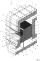
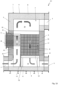
- the heat storage device 1 comprises a container 2 which is cuboid in the broadest sense and in which an interior space 3 is formed which extends in the vertical direction between a container ceiling 4 and a container bottom 5 and in the transverse directions between four side walls 6.
- the container 2 is provided with a loading opening 7 on a side wall 6 close to the container bottom 5, with an inlet/outlet opening 8 on another side wall 6 close to the container bottom 5, and with a discharge opening 9 on this side wall 6 adjacent to the container ceiling 4.
- the loading opening 7, the inlet/outlet opening 8, and the discharge opening 9 can be connected to lines of a piping system.
- a maintenance opening 10 is formed in a central region in the vertical direction, which can be closed in a gas-tight manner by means of a detachable wall element 11.
- the side walls 6, the container ceiling 4 and the container bottom 5 are each provided with high-temperature-resistant insulation layers 12.
- the interior space 3 of the container 2 has essentially cuboid dimensions. Furthermore, a partition wall 13 with a substantially U-shaped cross-section is formed in the interior space 3.
- the partition wall 13 stands on the container bottom 5 and has a vertical orientation. The short sides of the partition wall 13 border the side wall 6, on which the maintenance opening 10 is formed.
- the interior 3 is spanned by a grid structure 14, which has a horizontal orientation and is attached to the side walls 6 and the partition wall 13 and/or stands on the container bottom 5 via feet 22.
- the grid structure 14 forms a support structure or support construction.
- the partition wall 13 separates a storage chamber 15 from a heater chamber 16 of the interior space 3.
- the storage chamber 15 accommodates a heat storage medium 17, which consists of stacked ceramic molded blocks 18, each having a square base and a honeycomb structure, the honeycombs of which form flow channels extending in the vertical direction or vertical direction of the heat storage device 1.
- the heat storage means 17 can also be formed from a fill or the like.
- the shaped blocks 18 extend from the grid structure 14 to close to the upper edge of the partition wall 13 and encompass, as Figure 3 can be seen, the partition wall 13 on its three sides.
- the heater chamber 16 forms a heating channel, which is bounded at the bottom by the grid structure 14 and on which a stack of shaped blocks 19 is arranged as a support structure, each of which also has a honeycomb structure and corresponds to the shaped blocks 18 arranged in the storage chamber 15.
- the stack of shaped blocks 19 has a height that is less than that of the shaped blocks 18 in the storage chamber 15.
- a heating arrangement 20 is arranged on the shaped blocks 19, which represents an electrical heating device and is connected via connections 21 to a power source, for example to a wind turbine, a photovoltaic system and/or the power grid.
- An upper side of the heating arrangement 20 is approximately aligned with the upper side of the heat storage medium 17 in the storage space 15.
- the maintenance opening 10 can be closed by means of a removable wall element 11.
- the wall element 11 has an insulation plug on the inside.
- the storage space 15 and the heater space 16 are connected to each other via an open volume 24 of the interior space 3, which is arranged above the heater space 16 provided with the heating system or above the storage space 15 filled by the heat storage medium 17 and forms a gas distribution space.
- a gas distribution chamber is arranged, through which gas can flow from the loading opening 7 into the heater chamber 16.
- a gas distribution chamber 25 is arranged, which is connected to the inlet/outlet opening 8.
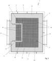
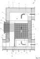
- a heat storage device 1' is shown, which represents an alternative embodiment and largely corresponds to that according to the Figures 1 to 3 corresponds, but differs from it in that the container 2 comprises a side wall 6' on the side of the maintenance opening 10, which has an outwardly offset projection 23.
- the container 2 comprises a side wall 6' on the side of the maintenance opening 10, which has an outwardly offset projection 23.
- a partition wall 13' which separates a heater chamber 16 from a storage chamber 15 of the interior 3, to be aligned with the inside of the side wall 6'.
- heat storage device 1' corresponds to the heat storage device according to the Figures 1 to 3 trained, so reference is made to the relevant description.
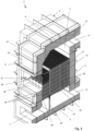
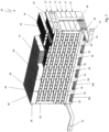
- the heating arrangement 20 of the heating system arranged in the heater chamber 16 of the above-described heat storage devices is shown in isolation.
- the heating arrangement 20 is provided on the bottom side with two rows of six shaped blocks 26 arranged one behind the other, which form a support structure and each have a honeycomb structure and whose channels formed by the honeycombs allow flow in the vertical direction.
- the shaped blocks 26 are ceramic shaped blocks which are arranged on Cordierite base.
- the heating arrangement 20 is delimited by a layer forming a cover 29 of shaped blocks 30 arranged next to one another, which also have a honeycomb structure and whose channels formed by the honeycombs are aligned in the vertical direction and through which flow can take place. Furthermore, the heating arrangement 20 comprises two connection contacts 31 and 32, which are connected to a power source or a power grid.
- the heating units 28 are basically composed of identical parts and each comprise two bearing elements 33 and a heating device 34.
- the bearing elements 33 are each formed from a ceramic molded block made from cordierite and having a honeycomb structure.
- the individual honeycombs of the bearing elements 33 each form a channel extending in the vertical direction and each have a square footprint.
- the bearing elements 33 each have a substantially U-shaped cross-section, so that a base plate 35 and two side walls 36 are formed, which delimit a receiving space for the precise accommodation of the heating device 34.
- the base plates 35 of the bearing elements 33 each have, in the region of the lateral edges, a recess 37 with a rectangular cross-section, into which the upper side of the corresponding side wall 36 of the underlying bearing element 33 engages when stacked. This ensures a precisely positioned arrangement of the bearing elements 33 arranged one above the other. Upper ribs of the shaped blocks 26 engage in the recesses 37 of the lowermost layer of heating units 28.
- the side walls 36 and the base plate 35 of a bearing element 33 are made in one piece.
- the side walls 36 are separate components, each mounted on a base plate.
- adjacent bearing elements each share a side wall, meaning this side wall overlaps adjacent base plates 35.
- the side walls 36 are provided on their upper side with a seal 38, which consists for example of a ceramic paper (cf. Fig. 8 ).
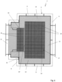
- the heating devices 34 of the heating units 28 are essentially identical in construction and each have an inflow base area, which in the present case corresponds to the area between the side walls 36 of two successively arranged bearing elements 33. In the installed position, the heating device 34 rests on the base plates 35 of these two bearing elements 33. As can be seen in particular from the Figures 9 to 11 As can be seen, the heating devices 34 each comprise six heating plate units 39A, 39B, 39C, 39D, 39E and 39F, which are connected in series.
- the heating plate units 39A and 39B, the heating plate units 39B and 39C, the heating plate units 39C and 39D, the heating plate units 39D and 39E and the heating plate units 39E and 39F are each connected to one another via a contact plate 40, which is arranged on a respective end face of the heating device 34.
- a partition 41 is arranged between each adjacent heating plate unit, which partition is made of an electrically insulating material, for example a ceramic material, and also ensures electrical insulation between each adjacent contact plate 40.
- the heating device 34 comprises side walls 42, which, in the installed position, border on or bear against the respective side walls 36 of the respective two bearing elements 33.
- the heating device 34 has a first connection element 43 and a second connection element 44, wherein the connection elements 43 and 44 are each formed from a sheet metal part that is aligned with the contact plates 40 arranged on the respective end face of the heating device 34.
- the connection element 43 is electrically connected to one end face of the heating plate unit 39A, whereas the connection element 44 is electrically connected to one end face of the heating plate unit 39F.
- the individual heating plate units 39A, 39B, 39C, 39D, 39E and 39F each comprise a plurality of heating plate strips 45 and 46.
- corrugated heating strips 45 and flat heating strips 46 are arranged one behind the other in the stacking direction, the corrugated heating strips 45 being arranged with their wave crests on the adjacent flat heating plate strips 46.
- the outer corrugated heating plate strips 45 are also supported on the respective partition wall 41 or the respective side wall 42.
- the heating plate strips 45 and 46 are aligned parallel to one another and are each connected to one another via a spacer structure 47, which also establishes contact between the respective heating plate stack and the connection element 43 or 44, or the respective contact plate 40.
- the spacer structure 47 comprises shim plates 48 designed as spacer elements, which are arranged between the parallel end regions of adjacent heating plate strips and are welded or soldered to them.
- the shim plates 48 each have a thickness that corresponds to the amplitude of the corrugation of the corrugated heating plate strips 45.
- the corrugation of the heating plate strips 45 forms a honeycomb structure which provides a large inflow area for the gas flow flowing through the heating device 34.
- the spacer structure can be formed from a comb structure into which the end regions of the heating plate strips are inserted.
- the heating devices of the heating units in the various layers 27 of the heating arrangement 20 have different heights and/or different honeycomb channel shapes.
- the heating devices 34 of a layer 27 of the heating arrangement 20 are connected in series via contact plates 49. It is, of course, also conceivable to connect them in parallel. Furthermore, in the present embodiment, successive Layers are connected in parallel pairs via contact strips 50. In principle, the wiring of the heating devices 34 can be freely selected as required.
- thermocouple 51 is arranged in the cover 29 in a transverse bore of a shaped block 30.
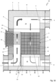
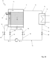
- a heat storage device 60 is shown, which largely corresponds to that according to the Figures 1 to 3 , but differs from it in that it does not include a stack heater of the type described above in the heater chamber 16, which forms a heating channel. Rather, resistance heating elements 61, which are formed from heating coils or the like and are connected to a power grid via a connection area 62, engage in the heater chamber 16. Otherwise, the heat storage device 60 corresponds to that according to the Figures 1 to 3 , which is why reference is made to the relevant description.
- the heat storage device 60 can be switched to a loading mode by means of corresponding valves, in which a gas stream consisting of warm air is introduced via a loading opening 7.
- This gas stream is, as Figure 13
- the gas stream is guided from bottom to top in the heater chamber 16 and heated by means of the resistance heating elements 61 and passed through the gas distribution chamber 24, which forms an open volume, through the heat storage medium 17, which is constructed from the shaped blocks 19.
- the shaped blocks 19 are thereby charged, i.e., heated.
- the gas stream which has then cooled again, is discharged from the heat storage device 60 via the gas distribution chamber 25 and the inlet/outlet opening 8.
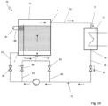
- a gas stream consisting of warm air is introduced into the heat storage device via the inlet/outlet opening 8 and is then passed from bottom to top through the gas distribution chamber 25 through the heat storage medium 17 formed from the shaped blocks 19, where it is heated. After heating, the heated gas stream is discharged from the heat storage device via the upper gas distribution chamber 24 and the discharge opening 9 for further use.
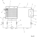
- FIG. 15 A heating operation without heat storage is shown for the heat storage device 60.
- a warm air gas stream is introduced into the heat storage device via the loading opening 7 and heated in the heater chamber 16 by means of the resistance heating elements 61. It is then discharged from the heat storage device 60 as a hot air gas stream via the upper gas distribution chamber 24 and the discharge opening 9.
- the described heat storage device 60 can also be operated in such a way that a warm air gas stream is introduced into the heat storage device via the loading opening 7 and heated by means of the resistance heating elements 61.
- the resulting hot air gas stream is divided in the upper gas distribution chamber 24 and, on the one hand, discharged from the heat storage device 60 via the discharge opening 9 and, on the other hand, is passed through the heat storage medium 17 formed from the shaped blocks 19 to charge it and is then discharged from the heat storage device via the lower gas distribution chamber 25 and the inlet/outlet opening 8.
- the heat storage device 60 can be operated such that a warm air gas stream is introduced via the loading opening 7 and the inlet/outlet opening 8.
- the gas stream introduced via the loading opening 7 is guided vertically upwards in the heater chamber 16 and heated by means of the resistance heating elements 61 and discharged via the upper gas distribution chamber 24 and the discharge opening 9.
- the warm air gas stream introduced via the inlet/outlet opening 8 is guided through the loaded heat storage medium 17 and heated there by heat exchange, before being subsequently discharged from the heat storage device via the upper gas distribution chamber 24 and the discharge opening 9.
- a heat storage system 70 which has a heat storage device 71 which can be configured either according to the Figures 1 to 6 illustrated embodiments or according to the Figures 12 to 17 shown embodiment.
- the heat storage system 70 comprises a line arrangement 72 which is connected to a consumer 73, which can be designed, for example, as a steam generator of a power plant.
- the line arrangement 72 comprises a line 74 which connects the discharge opening 9 of the heat storage device 71 to an inlet 75 of the consumer 73.
- the loading opening 7 of the heat storage device 71 is connected to a line 76 of the line arrangement 72, and the inlet/outlet opening 8 of the heat storage device 71 is connected to a line 77 of the line arrangement 72.
- An outlet 78 of the consumer 73 is connected to a line 79 which leads to a fan 80, which in turn is connected via the line 76 to the loading opening 7 of the heat storage device 71.
- a branch line 81 branches off from the line 76 and is connected to the line 77.
- a branch line 82 branches off from the line 79 and is also connected to the line 77.
- a valve 83 is arranged in line 76, a valve 84 is arranged in branch line 81, a valve 85 is arranged in branch line 82, and a valve 86 is arranged in line 79 upstream of the branch of branch line 82.
- a valve 84 is arranged in branch line 81
- a valve 85 is arranged in branch line 82
- a valve 86 is arranged in line 79 upstream of the branch of branch line 82.
- other suitable shut-off valves such as flaps or the like, can of course also be used.
- the heat storage device 71 is connected to a power source 87, which can be formed by the power grid or a photovoltaic system or even a wind turbine and is provided with a switch 88.
- a warm air gas stream is introduced from below into the heater chamber 16 of the heat storage device 71 via the loading opening 7 by means of the fan 80 with the valve 83 open.
- the switch 88 is closed, so that the heater arrangement is operated and the gas stream in the heater chamber 16 is heated.
- the heated gas stream is guided via the upper gas distribution chamber 24 into the storage chamber 15 and from top to bottom through the The heat is then passed to the heat storage bed, where the heat is transferred to it and stored there.
- a warm air/gas stream is then discharged from the heat storage device 71 via the inlet/outlet opening 8 and guided via line 77 and branch line 82 to the blower 80, where it can then be fed back to the heat storage device 71 in the manner described above. Valves 84 and 86 are closed in this loading mode.
- valves 84 and 86 are opened and valves 83 and 85 are closed.
- warm air is then introduced into the heat storage device 71 from below via the branch line 81 and the line 77 and the inlet/outlet opening 8 and heated in the storage bed formed by the heat storage medium 17.
- the resulting hot air gas stream is discharged from the top of the heat storage device 71 via the discharge opening 9 and made available to the consumer 73 via the line 74.
- This consumer releases warm air, which can be fed back to the heat storage device 71 by means of the fan 80 in the manner described above.
- valves 84 and 85 are closed, whereas valves 83 and 86 are open.
- warm air can then be introduced into the heater chamber 16 of the heat storage device 71 and heated there.
- the resulting hot air gas stream is led out of the heat storage device 71 via the discharge opening 9 and then fed to the consumer 73 via the line 74.
- the consumer 73 in turn emits a warm air gas stream, which is led via the line 79 to the fan 80 and can be fed back into the heat storage device 71 in the manner described above.
- An embodiment of a heat storage system (not shown in detail) can be designed as an at least partially open system, in which the air exiting the consumer is released entirely or partially into the environment. A corresponding amount of ambient air is then drawn in on the intake side of the fan when the heat storage device is discharged. Otherwise, this embodiment can correspond to the embodiment described above.
Landscapes
- Engineering & Computer Science (AREA)
- Thermal Sciences (AREA)
- Mechanical Engineering (AREA)
- General Engineering & Computer Science (AREA)
- Physics & Mathematics (AREA)
- Chemical & Material Sciences (AREA)
- Combustion & Propulsion (AREA)
- Dispersion Chemistry (AREA)
- Central Heating Systems (AREA)
- Resistance Heating (AREA)
- Direct Air Heating By Heater Or Combustion Gas (AREA)
- Surface Heating Bodies (AREA)
- Heat-Pump Type And Storage Water Heaters (AREA)
- Thermal Insulation (AREA)
- Pipe Accessories (AREA)
- Wind Motors (AREA)
Priority Applications (3)
| Application Number | Priority Date | Filing Date | Title |
|---|---|---|---|
| MA65243A MA65243B1 (fr) | 2020-05-04 | 2021-04-29 | Dispositif de chauffage, système de chauffage, dispositif de stockage d'énergie thermique et système de stockage d'énergie thermique |
| SI202130337T SI4257907T1 (sl) | 2020-05-04 | 2021-04-29 | Grelna naprava, grelni sistem, naprava za hranjenje toplote in sistem za hranjenje toplote |
| HRP20251030TT HRP20251030T1 (hr) | 2020-05-04 | 2021-04-29 | Uređaj za grijanje, sustav grijanja, uređaj za pohranu topline i sustav za pohranu topline |
Applications Claiming Priority (3)
| Application Number | Priority Date | Filing Date | Title |
|---|---|---|---|
| DE102020111987.9A DE102020111987B4 (de) | 2020-05-04 | 2020-05-04 | Heizeinrichtung |
| EP21725419.2A EP4146915B1 (de) | 2020-05-04 | 2021-04-29 | Heizeinrichtung, heizsystem, wärmespeichervorrichtung und wärmespeichersystem |
| PCT/EP2021/061303 WO2021224109A1 (de) | 2020-05-04 | 2021-04-29 | Heizeinrichtung, heizsystem, wärmespeichervorrichtung und wärmespeichersystem |
Related Parent Applications (2)
| Application Number | Title | Priority Date | Filing Date |
|---|---|---|---|
| EP21725419.2A Division EP4146915B1 (de) | 2020-05-04 | 2021-04-29 | Heizeinrichtung, heizsystem, wärmespeichervorrichtung und wärmespeichersystem |
| EP21725419.2A Division-Into EP4146915B1 (de) | 2020-05-04 | 2021-04-29 | Heizeinrichtung, heizsystem, wärmespeichervorrichtung und wärmespeichersystem |
Publications (3)
| Publication Number | Publication Date |
|---|---|
| EP4257907A2 EP4257907A2 (de) | 2023-10-11 |
| EP4257907A3 EP4257907A3 (de) | 2023-11-15 |
| EP4257907B1 true EP4257907B1 (de) | 2025-06-04 |
Family
ID=75914487
Family Applications (3)
| Application Number | Title | Priority Date | Filing Date |
|---|---|---|---|
| EP23193075.1A Active EP4257907B1 (de) | 2020-05-04 | 2021-04-29 | Heizeinrichtung, heizsystem, wärmespeichervorrichtung und wärmespeichersystem |
| EP23193090.0A Active EP4253892B1 (de) | 2020-05-04 | 2021-04-29 | Heizeinrichtung, heizsystem, wärmespeichervorrichtung und wärmespeichersystem |
| EP21725419.2A Active EP4146915B1 (de) | 2020-05-04 | 2021-04-29 | Heizeinrichtung, heizsystem, wärmespeichervorrichtung und wärmespeichersystem |
Family Applications After (2)
| Application Number | Title | Priority Date | Filing Date |
|---|---|---|---|
| EP23193090.0A Active EP4253892B1 (de) | 2020-05-04 | 2021-04-29 | Heizeinrichtung, heizsystem, wärmespeichervorrichtung und wärmespeichersystem |
| EP21725419.2A Active EP4146915B1 (de) | 2020-05-04 | 2021-04-29 | Heizeinrichtung, heizsystem, wärmespeichervorrichtung und wärmespeichersystem |
Country Status (22)
| Country | Link |
|---|---|
| US (1) | US20230194124A1 (pt) |
| EP (3) | EP4257907B1 (pt) |
| JP (3) | JP7598947B2 (pt) |
| CN (1) | CN115605671B (pt) |
| AU (4) | AU2021268992A1 (pt) |
| BR (1) | BR112022021825A2 (pt) |
| CA (3) | CA3263845A1 (pt) |
| CL (2) | CL2022003064A1 (pt) |
| DE (1) | DE102020111987B4 (pt) |
| DK (3) | DK4146915T3 (pt) |
| ES (3) | ES3040457T3 (pt) |
| FI (3) | FI4257907T3 (pt) |
| HR (3) | HRP20251030T1 (pt) |
| HU (3) | HUE069841T2 (pt) |
| LT (3) | LT4257907T (pt) |
| MA (2) | MA64769B1 (pt) |
| PL (3) | PL4146915T3 (pt) |
| PT (3) | PT4253892T (pt) |
| RS (1) | RS66413B1 (pt) |
| SI (3) | SI4146915T1 (pt) |
| WO (1) | WO2021224109A1 (pt) |
| ZA (1) | ZA202211237B (pt) |
Families Citing this family (2)
| Publication number | Priority date | Publication date | Assignee | Title |
|---|---|---|---|---|
| WO2023174911A1 (en) * | 2022-03-14 | 2023-09-21 | Timothy Patrick Cooper | Thermal energy storage system |
| EP4481293A1 (en) * | 2023-06-19 | 2024-12-25 | Heatrix GmbH | Electric heater and method for providing process heat |
Family Cites Families (43)
| Publication number | Priority date | Publication date | Assignee | Title |
|---|---|---|---|---|
| DE489379C (de) * | 1927-11-25 | 1930-01-17 | Siemens Schuckertwerke Akt Ges | Elektrischer Winderhitzer |
| DE718229C (de) * | 1937-11-30 | 1942-03-06 | Alessandru Beldimano | Verfahren und Vorrichtung zur Entnahme von Waermeenergie aus Waermespeichern |
| US3111979A (en) * | 1960-03-07 | 1963-11-26 | Lennox Ind Inc | Dual fuel burner construction |
| DE1779952A1 (de) * | 1967-02-22 | 1972-05-25 | Everken Olsberger Huette Kg | Elektrischer Speicherofen |
| GB1267803A (en) * | 1968-04-03 | 1972-03-22 | Laporte Titanium Ltd | Improvements in and relating to the heating of gases |
| CA933993A (en) * | 1970-12-09 | 1973-09-18 | J. Fedor Robert | Electric resistance heating element |
| DE2432904A1 (de) * | 1973-07-19 | 1975-02-06 | Atomic Energy Authority Uk | Heizelement zum erhitzen von stroemungsmitteln |
| DE2451736C3 (de) * | 1974-10-31 | 1979-03-01 | G. Bauknecht Gmbh, Elektrotechnische Fabriken, 7000 Stuttgart | Speicherheizgerät |
| GB1551818A (en) * | 1975-05-06 | 1979-09-05 | Ti Creda Mfg | Air heating devices |
| JPS5553100Y2 (pt) * | 1975-11-07 | 1980-12-09 | ||
| GB1523316A (en) * | 1975-11-20 | 1978-08-31 | Standard Telephones Cables Ltd | Electric resistance heaters |
| JPS5553106Y2 (pt) * | 1976-06-10 | 1980-12-09 | ||
| DE2731115C2 (de) * | 1977-07-09 | 1982-09-23 | Didier-Werke Ag, 6200 Wiesbaden | Wärmespeicheranlage |
| US4286141A (en) * | 1978-06-22 | 1981-08-25 | Calmac Manufacturing Corporation | Thermal storage method and system utilizing an anhydrous sodium sulfate pebble bed providing high-temperature capability |
| JPS55111049U (pt) * | 1979-01-29 | 1980-08-04 | ||
| US4346285A (en) * | 1979-04-28 | 1982-08-24 | Murata Manufacturing Co., Ltd. | Heating device employing thermistor with positive coefficient characteristic |
| US4362149A (en) * | 1980-12-08 | 1982-12-07 | Rockwell International Corporation | Heat storage system and method |
| DE3328078A1 (de) * | 1983-08-03 | 1985-02-21 | Grote & Hartmann Gmbh & Co Kg, 5600 Wuppertal | Widerstandsheizelement |
| GB2152652A (en) * | 1984-01-09 | 1985-08-07 | Powramtic Limited | An electric storage heater |
| NO157640C (no) * | 1985-07-09 | 1988-04-20 | Nielsen Ingenioer Og Handelsak | Varmeaggregat. |
| JPH04344069A (ja) * | 1991-05-20 | 1992-11-30 | Mitsubishi Heavy Ind Ltd | 蓄熱装置 |
| JP2547608Y2 (ja) * | 1991-06-25 | 1997-09-10 | シャープ株式会社 | 空気加熱兼浄化装置 |
| DE19724734C2 (de) * | 1997-06-12 | 2000-06-29 | Behr Gmbh & Co | Elektrische Heizeinrichtung, insbesondere für ein Kraftfahrzeug |
| EP0937595B1 (de) * | 1998-02-20 | 2003-08-20 | smart gmbh | Heizungs- oder Klimaanlage für Fahrzeuge |
| IT249474Y1 (it) | 2000-02-17 | 2003-05-19 | Eltek Spa | Radiatore elettrico. |
| JP2005001447A (ja) | 2003-06-10 | 2005-01-06 | Denso Corp | 電気ヒータ、暖房用熱交換器および車両用空調装置 |
| DE102005001385B3 (de) * | 2004-12-22 | 2006-08-24 | Schütz GmbH & Co. KGaA | Elektrisches Luftheizregister |
| JP4302677B2 (ja) * | 2005-08-17 | 2009-07-29 | 中国電力株式会社 | 給湯配管再加熱システム、給湯システム、及び給湯方法 |
| JP3116121U (ja) * | 2005-08-26 | 2005-11-24 | 林 正 平 | 発熱板を用いた発熱装置 |
| DE102008030212A1 (de) * | 2007-10-18 | 2009-04-23 | Stego-Holding Gmbh | Heizvorrichtung und Wärmetauscher |
| KR100906938B1 (ko) | 2007-12-06 | 2009-07-10 | (주)하이코 | 온풍기용 면상 발열체 |
| AT506477B1 (de) * | 2008-02-21 | 2010-07-15 | Schweighofer Franz | Wärmespeichereinrichtung |
| KR20100055262A (ko) * | 2008-11-17 | 2010-05-26 | 현대자동차주식회사 | 고용량 피티씨 히터 |
| EP2730854B1 (en) * | 2012-11-12 | 2015-06-03 | Betacera Inc. | Car interior compartment heater |
| DE102013108319B4 (de) * | 2013-08-01 | 2016-10-20 | B + S Entwicklungsgesellschaft Mbh | Verfahren sowie Vorrichtung zur Energiespeicherung |
| KR101614523B1 (ko) * | 2014-04-25 | 2016-04-21 | 김형석 | 전기 히터식 제해 장치 및 이에 사용되는 전기 히터 구조체 |
| JP2016102615A (ja) * | 2014-11-28 | 2016-06-02 | パナホーム株式会社 | 蓄熱構造体 |
| EP3051223B1 (en) * | 2015-01-28 | 2017-11-08 | Mahle International GmbH | Electric heating device |
| JP6511636B2 (ja) * | 2015-01-28 | 2019-05-15 | パナソニックIpマネジメント株式会社 | ヒーター付きエアカーテン |
| EP3296660A1 (en) * | 2016-09-15 | 2018-03-21 | Mahle International GmbH | Electric heater |
| DE102017207691A1 (de) * | 2017-05-08 | 2018-11-08 | Fritz GmbH. & Co. KG | Stationäres Lagersystem für Batterien |
| JP6744884B2 (ja) * | 2018-03-06 | 2020-08-19 | 川崎重工業株式会社 | 貯気槽 |
| DE102019120448B4 (de) * | 2019-07-29 | 2024-03-07 | Kraftanlagen München Gmbh | Wärmespeichervorrichtung, Wärmespeichersystem und Verfahren zum Betreiben einer Wärmespeichervorrichtung |
-
2020
- 2020-05-04 DE DE102020111987.9A patent/DE102020111987B4/de active Active
-
2021
- 2021-04-29 FI FIEP23193075.1T patent/FI4257907T3/fi active
- 2021-04-29 LT LTEP23193075.1T patent/LT4257907T/lt unknown
- 2021-04-29 CA CA3263845A patent/CA3263845A1/en active Pending
- 2021-04-29 AU AU2021268992A patent/AU2021268992A1/en not_active Abandoned
- 2021-04-29 FI FIEP21725419.2T patent/FI4146915T3/fi active
- 2021-04-29 SI SI202130338T patent/SI4146915T1/sl unknown
- 2021-04-29 US US17/923,349 patent/US20230194124A1/en active Pending
- 2021-04-29 DK DK21725419.2T patent/DK4146915T3/da active
- 2021-04-29 EP EP23193075.1A patent/EP4257907B1/de active Active
- 2021-04-29 MA MA64769A patent/MA64769B1/fr unknown
- 2021-04-29 CN CN202180033167.6A patent/CN115605671B/zh active Active
- 2021-04-29 HR HRP20251030TT patent/HRP20251030T1/hr unknown
- 2021-04-29 HU HUE23193090A patent/HUE069841T2/hu unknown
- 2021-04-29 HR HRP20241785TT patent/HRP20241785T1/hr unknown
- 2021-04-29 JP JP2022566121A patent/JP7598947B2/ja active Active
- 2021-04-29 LT LTEPPCT/EP2021/061303T patent/LT4146915T/lt unknown
- 2021-04-29 EP EP23193090.0A patent/EP4253892B1/de active Active
- 2021-04-29 LT LTEP23193090.0T patent/LT4253892T/lt unknown
- 2021-04-29 RS RS20241426A patent/RS66413B1/sr unknown
- 2021-04-29 ES ES23193075T patent/ES3040457T3/es active Active
- 2021-04-29 SI SI202130249T patent/SI4253892T1/sl unknown
- 2021-04-29 ES ES23193090T patent/ES3014516T3/es active Active
- 2021-04-29 PT PT231930900T patent/PT4253892T/pt unknown
- 2021-04-29 MA MA65243A patent/MA65243B1/fr unknown
- 2021-04-29 CA CA3263841A patent/CA3263841A1/en active Pending
- 2021-04-29 PT PT217254192T patent/PT4146915T/pt unknown
- 2021-04-29 EP EP21725419.2A patent/EP4146915B1/de active Active
- 2021-04-29 DK DK23193075.1T patent/DK4257907T3/da active
- 2021-04-29 CA CA3181353A patent/CA3181353A1/en active Pending
- 2021-04-29 PL PL21725419.2T patent/PL4146915T3/pl unknown
- 2021-04-29 BR BR112022021825A patent/BR112022021825A2/pt unknown
- 2021-04-29 PL PL23193075.1T patent/PL4257907T3/pl unknown
- 2021-04-29 HU HUE21725419A patent/HUE073313T2/hu unknown
- 2021-04-29 DK DK23193090.0T patent/DK4253892T3/da active
- 2021-04-29 SI SI202130337T patent/SI4257907T1/sl unknown
- 2021-04-29 PL PL23193090.0T patent/PL4253892T3/pl unknown
- 2021-04-29 FI FIEP23193090.0T patent/FI4253892T3/fi active
- 2021-04-29 WO PCT/EP2021/061303 patent/WO2021224109A1/de not_active Ceased
- 2021-04-29 HR HRP20251009TT patent/HRP20251009T1/hr unknown
- 2021-04-29 ES ES21725419T patent/ES3039008T3/es active Active
- 2021-04-29 HU HUE23193075A patent/HUE073294T2/hu unknown
- 2021-04-29 PT PT231930751T patent/PT4257907T/pt unknown
-
2022
- 2022-10-13 ZA ZA2022/11237A patent/ZA202211237B/en unknown
- 2022-11-04 CL CL2022003064A patent/CL2022003064A1/es unknown
-
2024
- 2024-06-24 AU AU2024204294A patent/AU2024204294A1/en active Pending
- 2024-06-24 AU AU2024204295A patent/AU2024204295B2/en active Active
- 2024-07-05 JP JP2024108899A patent/JP2024129136A/ja active Pending
- 2024-07-05 JP JP2024108892A patent/JP7759443B2/ja active Active
- 2024-07-29 CL CL2024002282A patent/CL2024002282A1/es unknown
-
2025
- 2025-02-28 AU AU2025201491A patent/AU2025201491A1/en active Pending
Also Published As
Similar Documents
| Publication | Publication Date | Title |
|---|---|---|
| EP2247906B1 (de) | Wärmespeichereinrichtung | |
| EP3997405B1 (de) | Wärmespeichervorrichtung, wärmespeichersystem und verfahren zum betreiben einer wärmespeichervorrichtung | |
| DE102007046133B4 (de) | Wärmespeicher zur Speicherung von Energie | |
| EP3655631B1 (de) | Energiespeicher zum speichern von elektrischer energie als wärme und verfahren hierzu | |
| EP2601456B1 (de) | Hochtemperatur-wärmespeicher für solarthermische kraftwerke | |
| EP2350549B1 (de) | Vorrichtung und anlage zum zwischenspeichern thermischer energie | |
| DE69103455T2 (de) | Energiegewinnungssystem mit flachen Brennstoffzellen aus festen Elektrolyten. | |
| EP4257907B1 (de) | Heizeinrichtung, heizsystem, wärmespeichervorrichtung und wärmespeichersystem | |
| DE202020102486U1 (de) | Heizeinrichtung, Heizsystem, Wärmespeichervorrichtung und Wärmespeichersystem | |
| AT520477B1 (de) | Vorrichtung zum Erzeugen von Dampf | |
| DE3208378C2 (de) | Deckenstrahlungsheizung, insbesondere für Hallen | |
| DE102020008100A1 (de) | Heizsystem | |
| DE102020008102A1 (de) | Wärmespeichervorrichtung und Wärmespeichersystem | |
| DE2731391A1 (de) | Vorrichtung zur nutzbarmachung der restwaerme eines abgases | |
| EP2015006A2 (de) | Wärmepumpe | |
| DE202018107362U1 (de) | Heizvorrichtung | |
| DE102017011794B4 (de) | Peltier-Wärmetauscher | |
| WO2021228526A1 (de) | Zellenstapel mit beheizbarer endplatte | |
| DE3023094A1 (de) | Verfahren und vorrichtung zur dampferzeugung | |
| DE102006024341A1 (de) | Aufwindkraftwerk | |
| DE102022125653A1 (de) | Wärmespeichervorrichtung zum Beheizen und/oder zur Warmwassergewinnung eines Komplettgebäudes | |
| WO2023057439A1 (de) | Schutzkonzept für speichermaterial eines thermischen speichers, eine gud-anlage und ein verfahren | |
| DE102023129979A1 (de) | Thermovorrichtung und Verfahren zum Betrieb einer Thermovorrichtung | |
| AT270716B (de) | Verfahren zur Kühlung von heißen Abgasen und Kühlkamin zur Durchführung des Verfahrens | |
| DE7721822U1 (de) | Vorrichtung zur nutzbarmachung der restwaerme eines abgases |
Legal Events
| Date | Code | Title | Description |
|---|---|---|---|
| REG | Reference to a national code |
Ref country code: HR Ref legal event code: TUEP Ref document number: P20251030T Country of ref document: HR |
|
| PUAI | Public reference made under article 153(3) epc to a published international application that has entered the european phase |
Free format text: ORIGINAL CODE: 0009012 |
|
| STAA | Information on the status of an ep patent application or granted ep patent |
Free format text: STATUS: THE APPLICATION HAS BEEN PUBLISHED |
|
| REG | Reference to a national code |
Ref country code: DE Ref legal event code: R079 Free format text: PREVIOUS MAIN CLASS: F28D0017040000 Ipc: F24H0003040000 Ref country code: DE Ref legal event code: R079 Ref document number: 502021007684 Country of ref document: DE Free format text: PREVIOUS MAIN CLASS: F28D0017040000 Ipc: F24H0003040000 |
|
| AC | Divisional application: reference to earlier application |
Ref document number: 4146915 Country of ref document: EP Kind code of ref document: P |
|
| AK | Designated contracting states |
Kind code of ref document: A2 Designated state(s): AL AT BE BG CH CY CZ DE DK EE ES FI FR GB GR HR HU IE IS IT LI LT LU LV MC MK MT NL NO PL PT RO RS SE SI SK SM TR |
|
| PUAL | Search report despatched |
Free format text: ORIGINAL CODE: 0009013 |
|
| AK | Designated contracting states |
Kind code of ref document: A3 Designated state(s): AL AT BE BG CH CY CZ DE DK EE ES FI FR GB GR HR HU IE IS IT LI LT LU LV MC MK MT NL NO PL PT RO RS SE SI SK SM TR |
|
| RIC1 | Information provided on ipc code assigned before grant |
Ipc: H05B 3/24 20060101ALI20231010BHEP Ipc: F24H 7/04 20060101ALI20231010BHEP Ipc: F24H 3/04 20220101AFI20231010BHEP |
|
| STAA | Information on the status of an ep patent application or granted ep patent |
Free format text: STATUS: REQUEST FOR EXAMINATION WAS MADE |
|
| 17P | Request for examination filed |
Effective date: 20240321 |
|
| RAP3 | Party data changed (applicant data changed or rights of an application transferred) |
Owner name: KRAFTANLAGEN ENERGIES & SERVICES SE |
|
| RBV | Designated contracting states (corrected) |
Designated state(s): AL AT BE BG CH CY CZ DE DK EE ES FI FR GB GR HR HU IE IS IT LI LT LU LV MC MK MT NL NO PL PT RO RS SE SI SK SM TR |
|
| RAV | Requested validation state of the european patent: fee paid |
Extension state: TN Effective date: 20240321 Extension state: MA Effective date: 20240321 |
|
| GRAP | Despatch of communication of intention to grant a patent |
Free format text: ORIGINAL CODE: EPIDOSNIGR1 |
|
| STAA | Information on the status of an ep patent application or granted ep patent |
Free format text: STATUS: GRANT OF PATENT IS INTENDED |
|
| INTG | Intention to grant announced |
Effective date: 20241223 |
|
| GRAS | Grant fee paid |
Free format text: ORIGINAL CODE: EPIDOSNIGR3 |
|
| GRAA | (expected) grant |
Free format text: ORIGINAL CODE: 0009210 |
|
| STAA | Information on the status of an ep patent application or granted ep patent |
Free format text: STATUS: THE PATENT HAS BEEN GRANTED |
|
| AC | Divisional application: reference to earlier application |
Ref document number: 4146915 Country of ref document: EP Kind code of ref document: P |
|
| AK | Designated contracting states |
Kind code of ref document: B1 Designated state(s): AL AT BE BG CH CY CZ DE DK EE ES FI FR GB GR HR HU IE IS IT LI LT LU LV MC MK MT NL NO PL PT RO RS SE SI SK SM TR |
|
| REG | Reference to a national code |
Ref country code: GB Ref legal event code: FG4D Free format text: NOT ENGLISH |
|
| REG | Reference to a national code |
Ref country code: CH Ref legal event code: EP |
|
| REG | Reference to a national code |
Ref country code: DE Ref legal event code: R096 Ref document number: 502021007684 Country of ref document: DE |
|
| REG | Reference to a national code |
Ref country code: IE Ref legal event code: FG4D Free format text: LANGUAGE OF EP DOCUMENT: GERMAN |
|
| REG | Reference to a national code |
Ref country code: DK Ref legal event code: T3 Effective date: 20250825 Ref country code: FI Ref legal event code: FGE Ref country code: PT Ref legal event code: SC4A Ref document number: 4257907 Country of ref document: PT Date of ref document: 20250901 Kind code of ref document: T Free format text: AVAILABILITY OF NATIONAL TRANSLATION Effective date: 20250826 |
|
| REG | Reference to a national code |
Ref country code: SE Ref legal event code: TRGR |
|
| REG | Reference to a national code |
Ref country code: NL Ref legal event code: FP |
|
| REG | Reference to a national code |
Ref country code: MA Ref legal event code: VAGR Ref document number: 65243 Country of ref document: MA Kind code of ref document: B1 |
|
| REG | Reference to a national code |
Ref country code: EE Ref legal event code: FG4A Ref document number: E025260 Country of ref document: EE Effective date: 20250818 |
|
| PG25 | Lapsed in a contracting state [announced via postgrant information from national office to epo] |
Ref country code: BG Free format text: LAPSE BECAUSE OF FAILURE TO SUBMIT A TRANSLATION OF THE DESCRIPTION OR TO PAY THE FEE WITHIN THE PRESCRIBED TIME-LIMIT Effective date: 20250604 |
|
| PG25 | Lapsed in a contracting state [announced via postgrant information from national office to epo] |
Ref country code: RS Free format text: LAPSE BECAUSE OF FAILURE TO SUBMIT A TRANSLATION OF THE DESCRIPTION OR TO PAY THE FEE WITHIN THE PRESCRIBED TIME-LIMIT Effective date: 20250904 |
|
| REG | Reference to a national code |
Ref country code: HR Ref legal event code: T1PR Ref document number: P20251030 Country of ref document: HR |
|
| REG | Reference to a national code |
Ref country code: SK Ref legal event code: T3 Ref document number: E 46994 Country of ref document: SK |
|
| REG | Reference to a national code |
Ref country code: GR Ref legal event code: EP Ref document number: 20250401754 Country of ref document: GR Effective date: 20251009 Ref country code: ES Ref legal event code: FG2A Ref document number: 3040457 Country of ref document: ES Kind code of ref document: T3 Effective date: 20251031 |
|
| PG25 | Lapsed in a contracting state [announced via postgrant information from national office to epo] |
Ref country code: IS Free format text: LAPSE BECAUSE OF FAILURE TO SUBMIT A TRANSLATION OF THE DESCRIPTION OR TO PAY THE FEE WITHIN THE PRESCRIBED TIME-LIMIT Effective date: 20251004 |
|
| PG25 | Lapsed in a contracting state [announced via postgrant information from national office to epo] |
Ref country code: SM Free format text: LAPSE BECAUSE OF FAILURE TO SUBMIT A TRANSLATION OF THE DESCRIPTION OR TO PAY THE FEE WITHIN THE PRESCRIBED TIME-LIMIT Effective date: 20250604 |
|
| REG | Reference to a national code |
Ref country code: HU Ref legal event code: AG4A Ref document number: E073294 Country of ref document: HU |