EP4249712B1 - Auskupplungssystem für eine griffanordnung - Google Patents
Auskupplungssystem für eine griffanordnung Download PDFInfo
- Publication number
- EP4249712B1 EP4249712B1 EP22163916.4A EP22163916A EP4249712B1 EP 4249712 B1 EP4249712 B1 EP 4249712B1 EP 22163916 A EP22163916 A EP 22163916A EP 4249712 B1 EP4249712 B1 EP 4249712B1
- Authority
- EP
- European Patent Office
- Prior art keywords
- housing
- declutching
- axle
- lever
- head
- Prior art date
- Legal status (The legal status is an assumption and is not a legal conclusion. Google has not performed a legal analysis and makes no representation as to the accuracy of the status listed.)
- Active
Links
Images

Classifications
-
- E—FIXED CONSTRUCTIONS
- E05—LOCKS; KEYS; WINDOW OR DOOR FITTINGS; SAFES
- E05B—LOCKS; ACCESSORIES THEREFOR; HANDCUFFS
- E05B81/00—Power-actuated vehicle locks
- E05B81/54—Electrical circuits
- E05B81/90—Manual override in case of power failure
-
- E—FIXED CONSTRUCTIONS
- E05—LOCKS; KEYS; WINDOW OR DOOR FITTINGS; SAFES
- E05B—LOCKS; ACCESSORIES THEREFOR; HANDCUFFS
- E05B15/00—Other details of locks; Parts for engagement by bolts of fastening devices
- E05B15/0053—Other details of locks; Parts for engagement by bolts of fastening devices means providing a stable, i.e. indexed, position of lock parts
-
- E—FIXED CONSTRUCTIONS
- E05—LOCKS; KEYS; WINDOW OR DOOR FITTINGS; SAFES
- E05B—LOCKS; ACCESSORIES THEREFOR; HANDCUFFS
- E05B81/00—Power-actuated vehicle locks
- E05B81/54—Electrical circuits
- E05B81/64—Monitoring or sensing, e.g. by using switches or sensors
- E05B81/76—Detection of handle operation; Detection of a user approaching a handle; Electrical switching actions performed by door handles
-
- E—FIXED CONSTRUCTIONS
- E05—LOCKS; KEYS; WINDOW OR DOOR FITTINGS; SAFES
- E05B—LOCKS; ACCESSORIES THEREFOR; HANDCUFFS
- E05B85/00—Details of vehicle locks not provided for in groups E05B77/00 - E05B83/00
- E05B85/10—Handles
Definitions
- the invention relates to a declutching system for a handle arrangement of a motor vehicle, in particular in the case of automated door latches that are controlled via electric means.
- Automated door latches selectively lock or release vehicle door panels in an automated fashion.
- automated door latches are herein designated door latches provided with a manually operable handle element and a rotatably mounted transmission lever which is connected to the handle element and can be rotated by actuating the handle element to such an extent that it activates a switch for opening the door latch.
- the user or an electric panel actuator swings or slides the panel to grant physical access to the vehicle.
- Document DE102014117005 tries to solve this problem by proposing a handle arrangement wherein a rotatably transmission lever is connected to a handle element which is blocked into rotation by a declutching system when the handle element is actuated under a predetermined force threshold.
- a rotatably transmission lever is connected to a handle element which is blocked into rotation by a declutching system when the handle element is actuated under a predetermined force threshold.
- the invention intends to obviate at least partly this lack in the art.
- the object of the invention is to provide a compact declutching system for a handle arrangement of a motor vehicle.
- the invention relates to a declutching system for a handle arrangement of a motor vehicle comprising an axle whereon are arranged a housing and a declutching member, the declutching system presenting two positions, a clutch position wherein the declutching member blocks the housing in rotation around the axle by cooperating with a cam of the housing and a declutch position wherein the declutching member allows the housing to rotate around the axle,
- the declutching system of the invention takes the advantage to clutch and to declutch the rotation of the housing around the axle with a compact system which do not request the translation of a member along the axle.
- the force required to deform the elastic member is the torque of magnitude which has to be applied on the housing for its rational displacement around the axle.
- the declutching system moves from the clutched position to the declutched position when a torque of a magnitude above a predetermined threshold is applied on the housing. Accordingly, under normal circumstances, i.e., when the electrical panel actuator is operable, the declutching system is in its clutch position such that when the handles is actuated by a user with a torque of magnitude below the predetermined threshold, it will put into rotation a rotatably transmission lever until the latter be stopped into rotation by the declutching system.
- the clutch position of the declutching system of the invention gives a haptic sensation to the user informing him he enough extends the handle to trigger the electrical panel actuator and grant physical access to the vehicle.
- the housing When the user stops actuate the handle, the housing is drove back by the rotatably transmission lever and the declutching system returns to its clutch position.
- the elastic member returns from an active deformed shape to a passive shape blocking the housing in rotation.
- the declutching member presents two configurations corresponding to the two positions of the declutching system. Firstly, the declutching member has a block configuration wherein the head of the lever cooperates with the cam of the housing and blocks the latter into rotation around the axle. Secondly, the declutching member has a release configuration wherein the elastic member is deformed, and the head of the lever cooperates with an adjacent surface to the cam of the housing enabling the rotationally displacement of the housing around the axle. The declutching member passively moves from the release configuration to the block position because of the reversible shape property of the elastic member.
- the declutching member switches from the block configuration to the release configuration by the application of a load force by the cam of the housing onto the at head of the lever, pushing the latter in the direction of the elastic member and resulting in the deformation of the elastic member by compression in an opposite direction to the head of the lever.
- the elastic element is a spring or a reversible deformable pad.
- the housing comprising an inner wall
- the cam of the housing is arranged in the inner wall of the housing.
- the cam of the housing is a groove disposed along the axle.
- the groove has a U-shape cross section.
- the head of the lever can comprise a protrusion extending away from the elastic member and cooperating with the cam of the housing.
- the housing has a peripherical rib for actuating in rotation around the axle.
- the head of the lever is provided with a curbed portion overlaying the elastic element.
- the curbed portion allows to stop the movement of the lever when the latter is pushed by the housing and avoids supercharging the elastic member.
- the declutching member is disposed in a barrel of the axle.
- the invention also relates to a handle arrangement for a door lock comprising a declutching system as defined above.
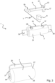
- Figure 1 to 3 represent different views of a declutching system 1 according to the invention and will be read together.
- the declutching system 1 of the invention is part of a vehicle handle (not shown) and comprises an axle 3 whereon are arranged a housing 5 and a declutching member 7.
- the declutching system 1 presents two positions, a clutch position (as represented in Figures 1, 2 and 4 ) and a declutch position (represented in Figure 5 ).
- the rotation of the housing 5 around the axle 3 is blocked or allowed by the declutching member 7.
- a torque of magnitude above a particular threshold is applied by the housing 5 on the declutching member 7, the declutching system 1 moves from the clutch position toward the declutch position and the housing 5 pivots around the axle 3.
- the housing 5 is arranged on the axle 3 in a rotationally displaceable manner and the declutching member 7 is arranged on the axle 3 in a rotationally and axially fixed manner. Accordingly, the declutching member 7 does not move around or along the axle 3.
- the housing 5 overlays the declutching member 7.
- the declutching member 7 comprises a pivotable arranged lever 9 and an elastic member 11.
- the elastic member 11 can be a compression spring or a reversible deformable pad.
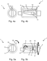
- the lever 9 is provided with a head 13 at its free end cooperating on one side with the elastic member 11 and on the other side with a cam 15 of the housing 5. In the clutch position of the declutching system 1, the elastic member 11 maintains the head 13 of the lever 9 in contact with the cam 15 of the housing (as represented in Figure 2 and 4b ).
- the cam 15 applies a load force on the lever 9.
- said load force is below the mechanical resistance of the elastic member 11, the lever 9 cannot compress it and the declutching system 1 remains in the clutch position.
- the load force of the cam 5 is higher than the mechanical resistance of the elastic member 11, the lever 9 compresses the elastic member 11 and the declutching system 1 moves from the clutch position to the declutch position allowing the housing 5 to continue its rotational movement around the axle 3.
- the head 13 of the lever 9 can be provided with a curbed potion 17 at its extremity for limiting the pivoting movement of the lever 9 and avoiding the lever 9 to supercharge the elastic member 11. Accordingly, the curbed portion 17 overlays the elastic member 11.
- the lever 9 has a base part 19 configured to pivot.
- the base part 19 is a hinged pin as represented on Figure 3 .
- the pivoting movement of the lever can be performed in any direction regarding the axle, and in particular along the axle or in a direction perpendicular to it.
- the head 13 of the lever 9 comprise a protrusion 21, extending away from the elastic member 11 and/or from the curbed portion 17, cooperating with the cam 15 of the housing 5.
- the cam 15 is arranged on the inner wall 23 of the housing 5.
- the cam 15 can be a groove disposed along the axle 3, as represented on Figure 2 .
- the said groove 15 can have a U-shape cross section or a V-shape cross section.
- the groove can end on one edge of the housing. This aspect of the invention facilitates the assembly of the declutching system, in which the housing is slipped around the axle and the protrusion of the head of the lever slides in the groove of the housing.
- the cam can have a dome shape.
- the housing 5 can be crossing.
- the housing 5 has a cylindrical hollow body 25 shape with two opened extremities 27.
- the body 25 of the housing 5 cooperates with the axle 3.
- One of the opened extremities 27 can have a dome shape with a through hole 29 at its apex cooperating with the axle 3 for limiting the translational movement of the housing along the axle 3.
- the housing 5 can be provided with a rib 25 a peripherical rib for actuating in rotation around the axle.
- the rib 25 is disposed along the axle.
- the axle 3 comprises a barrel 31 extending along its direction and wherein is arranged the declutching member 7. As represented, the declutching member 7 is then in a slot 33 arranged in the barrel 31.
- This aspect of the invention enhances the compact property. More specifically, the lever 9 and the elastic member 11 are in two respective slots (35, 37).
- the barrel 31 of the axle cooperates with one of the extremities 27 of the housing 5 to limit the translational displacement of the housing 5 along the axle 3.
- the housing overlays the declutching member 7 and the axle 3 excepted for the extremities 39 of the latter so it can be fixed on a bracket (not shown) of the handle arrangement.
- the axle 3 is provided with rectangular shaped extremities 39 designed to cooperate with the bracket in a fixed manner. Said shape of the extremities 39 avoids the axle 3 to pivot around them.
- Figures 4a and 4b are read together and show the clutch position of the declutching system 1.
- the head 13 of the lever 9 is here in contact with the cam 15 of the housing 5. More precisely, the protrusion of the head is in contact with the wall of the groove 15. A torque of magnitude is applied on the rib of the housing 5, but with a force below the mechanical resistance of the elastic member 11. Consequently, the head 13 of the lever 9 is not pushed by the wall of the groove 15, and the lever 9 does not pivot.
- Figures 5a and 5b are read together and show the declutch position of the declutching system 1.
- the rib 25 of the housing has been actuated with a magnitude of force above the mechanical resistance of the elastic member.
- the head 13 of the lever 9 is not anymore in contact with the cam 15 of the housing 5. Indeed, the wall of the groove 15 pushed down the head 13 of the lever 9 resulting in the pivoting of the base 19 of the lever 9 rotated around the hinged pin.
- the groove 15 is now empty while the head 13 cooperates with a surface of the inner wall 23 of the housing 5 adjacent to the groove 15. Accordingly, the housing 5 is free to rotate around the axle 3.
- the head 13 of the lever 9 is maintained pushed down by the said surface of the inner wall 23 of the housing 5.
- the elastic member 11 is compressed by the head 13 of the lever 9 and the curbed portion 17 of the head 13 of the lever 9 contacts the bottom of the lever's slot, stopping the rotation of the lever 9.
Landscapes
- Lock And Its Accessories (AREA)
- Mechanical Operated Clutches (AREA)
Claims (9)
- Auskupplungssystem (1) für eine Griffanordnung eines Kraftfahrzeugs, das eine Achse (3) umfasst, wobei ein Gehäuse (5) und ein Auskupplungselement (7) angeordnet sind, wobei das Auskupplungssystem (1) zwei Stellungen aufweist, eine Einkupplungsstellung, in der das Kupplungselement (7) das Gehäuse (5) durch Zusammenwirken mit einem Nocken (15) des Gehäuses (5) durch Drehen um die Achse (3) blockiert, und eine Auskupplungsstellung, in der das Kupplungselement (7) das Gehäuse (5) um die Achse (3) drehen lässt,
dadurch gekennzeichnet, dassdas Kupplungselement (7) einen schwenkbar angeordneten Hebel (9) und ein elastisches Element umfasst (11), wobei der Hebel (9) an seinem freien Ende mit einem Kopf (13) versehen ist, der mit dem elastischen Element (11) zusammenwirkt,wobei in der Einkupplungsstellung des Auskupplungssystems (1) der Kopf (13) des Hebels (9) mit dem Nocken (15) des Gehäuses (5) zusammenwirkt, um zu verhindern, dass sich das Gehäuse (5) um die Achse (3) dreht, und durch das elastische Element (11) in seiner Stellung gehalten wird,und wobei in der Auskupplungsstellung des Auskupplungssystems (1) der Kopf (13) des Hebels (9) das elastische Element (11) zusammendrückt, wodurch eine Drehbewegung des Gehäuses (5) um die Achse (3) ermöglicht wird. - Auskupplungssystem nach Anspruch 1, wobei das elastische Element (11) eine Druckfeder oder ein reversibel verformbares Polsterstück ist.
- Auskupplungssystem (1) nach Anspruch 1 oder 2, wobei das Gehäuse (5) eine Innenwand (23) umfasst, wobei der Nocken (15) des Gehäuses (5) in der Innenwand (23) des Gehäuses (5) angeordnet ist.
- Auskupplungssystem (1) nach Anspruch 3, wobei der Nocken (15) des Gehäuses (5) eine Nut (15) ist, die entlang der Achse (3) angeordnet ist, wobei die Nut (15) vorzugsweise einen U-förmigen Querschnitt aufweist.
- Auskupplungssystem (1) nach Anspruch 4, wobei der Kopf (13) des Hebels (9) einen Vorsprung (21) aufweist, der sich von dem elastischen Element (11) weg erstreckt und mit dem Nocken (15) des Gehäuses (5) zusammenwirkt.
- Auskupplungssystem nach einem der Ansprüche 1 bis 5, wobei das Gehäuse (5) eine periphere Rippe (25) zur Betätigung in Drehung um die Achse (3) aufweist.
- Auskupplungssystem nach (1) nach einem der Ansprüche 1 bis 6, wobei der Kopf (13) des Hebels (9) mit einem gekrümmten Abschnitt (17) versehen ist, der das elastische Element (11) überlagert.
- Auskupplungssystem (1) nach einem der Ansprüche 1 bis 7, wobei das Auskupplungselement (7) in einem Zylinder (31) der Achse (3) angeordnet ist.
- Griffanordnung für ein Türschloss, umfassend ein Auskupplungssystem (1) nach einem der Ansprüche 1 bis 8.
Priority Applications (4)
| Application Number | Priority Date | Filing Date | Title |
|---|---|---|---|
| EP22163916.4A EP4249712B1 (de) | 2022-03-23 | 2022-03-23 | Auskupplungssystem für eine griffanordnung |
| ES22163916T ES3015191T3 (en) | 2022-03-23 | 2022-03-23 | Declutching system for a handle arrangement |
| US18/188,746 US12559998B2 (en) | 2022-03-23 | 2023-03-23 | Declutching system for a handle arrangement |
| CN202310295524.7A CN116804349A (zh) | 2022-03-23 | 2023-03-23 | 用于手柄装置的脱离系统 |
Applications Claiming Priority (1)
| Application Number | Priority Date | Filing Date | Title |
|---|---|---|---|
| EP22163916.4A EP4249712B1 (de) | 2022-03-23 | 2022-03-23 | Auskupplungssystem für eine griffanordnung |
Publications (2)
| Publication Number | Publication Date |
|---|---|
| EP4249712A1 EP4249712A1 (de) | 2023-09-27 |
| EP4249712B1 true EP4249712B1 (de) | 2024-12-04 |
Family
ID=80930195
Family Applications (1)
| Application Number | Title | Priority Date | Filing Date |
|---|---|---|---|
| EP22163916.4A Active EP4249712B1 (de) | 2022-03-23 | 2022-03-23 | Auskupplungssystem für eine griffanordnung |
Country Status (4)
| Country | Link |
|---|---|
| US (1) | US12559998B2 (de) |
| EP (1) | EP4249712B1 (de) |
| CN (1) | CN116804349A (de) |
| ES (1) | ES3015191T3 (de) |
Family Cites Families (25)
| Publication number | Priority date | Publication date | Assignee | Title |
|---|---|---|---|---|
| US1852552A (en) * | 1929-07-05 | 1932-04-05 | Altorfer Bros Co | Clutch |
| DE2829925A1 (de) * | 1978-07-07 | 1980-01-24 | Fichtel & Sachs Ag | Schliess- und/oder verriegelungseinrichtung mit fahrzeugtueren |
| FR2559827B1 (fr) * | 1984-02-17 | 1986-07-04 | Mecanismes Comp Ind De | Dispositif d'embrayage et de debrayage, notamment pour un mecanisme de condamnation electrique de serrure pour portiere de vehicule automobile |
| CA1317323C (en) * | 1988-03-19 | 1993-05-04 | Shinjiro Yamada | Clutch for actuator for automobile |
| US4850466A (en) * | 1988-05-19 | 1989-07-25 | General Motors Corporation | Clutch for power door lock actuator |
| JP2616598B2 (ja) * | 1991-05-14 | 1997-06-04 | 三菱電機株式会社 | モータ式アクチュエータ |
| US5946955A (en) * | 1997-04-30 | 1999-09-07 | Stephen J. Suggs | Door latch/lock control |
| GB2330802A (en) * | 1997-10-28 | 1999-05-05 | Alliedsignal Ltd | Webbing sensor |
| DE19858414A1 (de) * | 1998-12-17 | 2000-06-21 | Bayerische Motoren Werke Ag | Crashsperre an einem Türschloß eines Fahrzeugs |
| ES2189571B2 (es) * | 1999-12-31 | 2004-06-01 | Escudos Kala Internacional, S.L. | Mecanismo de embrague para cerraduras electronicas. |
| US6594861B2 (en) * | 2001-07-20 | 2003-07-22 | Strattec Security Corporation | Motor vehicle door handle apparatus and method of installation |
| US7000751B2 (en) * | 2003-12-23 | 2006-02-21 | Zf Meritor, Llc | Normally open clutch assembly device |
| US8408612B2 (en) * | 2004-04-30 | 2013-04-02 | Intier Automotive Closures Inc | Rotary locking mechanism for outside vehicle door handle |
| FR2953548B1 (fr) * | 2009-12-08 | 2012-03-16 | Valeo Securite Habitacle | Systeme pour ouvrant de vehicule automobile muni d'un ressort |
| DE102013106176A1 (de) * | 2013-06-13 | 2014-12-18 | Huf Hülsbeck & Fürst Gmbh & Co. Kg | Türgriffanordnung für ein Kraftfahrzeug |
| DE102014117005A1 (de) | 2014-11-20 | 2016-05-25 | Witte Automotive Gmbh | Griffanordnung für ein Türschloss |
| JP6137761B2 (ja) * | 2015-08-05 | 2017-05-31 | サカエ理研工業株式会社 | 車両用ドアハンドル装置 |
| DE102016104095A1 (de) * | 2016-03-07 | 2017-09-07 | Witte Automotive Gmbh | Türgriffanordnung |
| FR3060630B1 (fr) * | 2016-12-20 | 2019-11-22 | Akwel | Commande d'ouverture affleurante a ejection et retraction mecanique ou electrique. |
| EP3421702B1 (de) * | 2017-06-29 | 2020-05-13 | U-Shin Deutschland Zugangssysteme GmbH | Fahrzeugtürgriffanordnung |
| JP7000736B2 (ja) * | 2017-08-15 | 2022-01-19 | 株式会社アイシン | 車両用ハンドル装置 |
| US11187008B2 (en) * | 2018-04-18 | 2021-11-30 | Assa Abloy Korea | Clutch engagement assembly of door lock and driving device thereof |
| DE102019200851A1 (de) * | 2019-01-24 | 2020-07-30 | Witte Automotive Gmbh | Griffanordnung für ein Türschloss |
| WO2021046790A1 (zh) * | 2019-09-12 | 2021-03-18 | 南京东屋电气有限公司 | 一种带有双向超越离合器的电子门锁及其使用方法 |
| DE102020112935A1 (de) * | 2020-05-13 | 2021-11-18 | Huf Hülsbeck & Fürst Gmbh & Co. Kg | Kraftfahrzeug-Türgriffanordnung |
-
2022
- 2022-03-23 EP EP22163916.4A patent/EP4249712B1/de active Active
- 2022-03-23 ES ES22163916T patent/ES3015191T3/es active Active
-
2023
- 2023-03-23 US US18/188,746 patent/US12559998B2/en active Active
- 2023-03-23 CN CN202310295524.7A patent/CN116804349A/zh active Pending
Also Published As
| Publication number | Publication date |
|---|---|
| CN116804349A (zh) | 2023-09-26 |
| US20230304331A1 (en) | 2023-09-28 |
| EP4249712A1 (de) | 2023-09-27 |
| US12559998B2 (en) | 2026-02-24 |
| ES3015191T3 (en) | 2025-04-30 |
Similar Documents
| Publication | Publication Date | Title |
|---|---|---|
| CN110273601B (zh) | 用于机动车辆的具有线性致动器的打开装置 | |
| US6685239B2 (en) | Vehicle door opening closing device | |
| CN108012549B (zh) | 具有不同类型的门锁操作的门锁操作器 | |
| EP3141679B1 (de) | Elektronischer handgriff für eine fahrzeugtür | |
| KR20020026164A (ko) | 플랩, 도어 등과 같은 차량의 로킹 가능한 가동 부분의개방 메카니즘 및/또는 폐쇄 메카니즘의 작동을 위한 장치 | |
| JP4759152B2 (ja) | スライドドアのロックコントローラ | |
| EP4174260B1 (de) | Paneelschloss | |
| CN113107289A (zh) | 用于车辆的电动车门闩锁设备 | |
| WO2017077077A1 (en) | Handle for a vehicle door | |
| JPS58106074A (ja) | 自動車用のドア錠 | |
| EP2060711A2 (de) | Türverriegelungsvorrichtung für Fahrzeuge | |
| US6365851B1 (en) | Electrical switch extraction handle with lockout | |
| CN114961445B (zh) | 微波炉的联锁装置和微波炉 | |
| EP4249712B1 (de) | Auskupplungssystem für eine griffanordnung | |
| US11365565B2 (en) | Motor-driven door latch for vehicle | |
| CN1881495B (zh) | 带有可转动锁定装置的电开关设备的致动器 | |
| CN118215976B (zh) | 按压开关、车门和汽车 | |
| EP4249713B1 (de) | Auskupplungssystem für eine griffanordnung | |
| US20240003164A1 (en) | Handle arrangement | |
| JP6933491B2 (ja) | 車両用ロック装置 | |
| CN114961443B (zh) | 微波炉的联锁装置和微波炉 | |
| EP3945191B1 (de) | Elektronischer griff für eine fahrzeugtür | |
| EP4198228A1 (de) | Elektronischer handgriff für eine fahrzeugtür | |
| JP4440025B2 (ja) | 開閉装置 | |
| US20250243695A1 (en) | Safety device for a vehicle door handle assembly |
Legal Events
| Date | Code | Title | Description |
|---|---|---|---|
| PUAI | Public reference made under article 153(3) epc to a published international application that has entered the european phase |
Free format text: ORIGINAL CODE: 0009012 |
|
| STAA | Information on the status of an ep patent application or granted ep patent |
Free format text: STATUS: THE APPLICATION HAS BEEN PUBLISHED |
|
| AK | Designated contracting states |
Kind code of ref document: A1 Designated state(s): AL AT BE BG CH CY CZ DE DK EE ES FI FR GB GR HR HU IE IS IT LI LT LU LV MC MK MT NL NO PL PT RO RS SE SI SK SM TR |
|
| STAA | Information on the status of an ep patent application or granted ep patent |
Free format text: STATUS: REQUEST FOR EXAMINATION WAS MADE |
|
| 17P | Request for examination filed |
Effective date: 20240206 |
|
| RBV | Designated contracting states (corrected) |
Designated state(s): AL AT BE BG CH CY CZ DE DK EE ES FI FR GB GR HR HU IE IS IT LI LT LU LV MC MK MT NL NO PL PT RO RS SE SI SK SM TR |
|
| RAP3 | Party data changed (applicant data changed or rights of an application transferred) |
Owner name: MINEBEA ACCESSSOLUTIONS ITALIA S.P.A. |
|
| GRAP | Despatch of communication of intention to grant a patent |
Free format text: ORIGINAL CODE: EPIDOSNIGR1 |
|
| STAA | Information on the status of an ep patent application or granted ep patent |
Free format text: STATUS: GRANT OF PATENT IS INTENDED |
|
| RIC1 | Information provided on ipc code assigned before grant |
Ipc: E05B 81/76 20140101ALI20240619BHEP Ipc: E05B 15/00 20060101ALI20240619BHEP Ipc: E05B 85/10 20140101ALI20240619BHEP Ipc: E05B 47/06 20060101ALI20240619BHEP Ipc: E05B 81/90 20140101AFI20240619BHEP |
|
| INTG | Intention to grant announced |
Effective date: 20240705 |
|
| GRAS | Grant fee paid |
Free format text: ORIGINAL CODE: EPIDOSNIGR3 |
|
| GRAA | (expected) grant |
Free format text: ORIGINAL CODE: 0009210 |
|
| STAA | Information on the status of an ep patent application or granted ep patent |
Free format text: STATUS: THE PATENT HAS BEEN GRANTED |
|
| AK | Designated contracting states |
Kind code of ref document: B1 Designated state(s): AL AT BE BG CH CY CZ DE DK EE ES FI FR GB GR HR HU IE IS IT LI LT LU LV MC MK MT NL NO PL PT RO RS SE SI SK SM TR |
|
| REG | Reference to a national code |
Ref country code: CH Ref legal event code: EP |
|
| REG | Reference to a national code |
Ref country code: DE Ref legal event code: R096 Ref document number: 602022008289 Country of ref document: DE |
|
| REG | Reference to a national code |
Ref country code: IE Ref legal event code: FG4D |
|
| REG | Reference to a national code |
Ref country code: LT Ref legal event code: MG9D |
|
| REG | Reference to a national code |
Ref country code: NL Ref legal event code: MP Effective date: 20241204 |
|
| PG25 | Lapsed in a contracting state [announced via postgrant information from national office to epo] |
Ref country code: HR Free format text: LAPSE BECAUSE OF FAILURE TO SUBMIT A TRANSLATION OF THE DESCRIPTION OR TO PAY THE FEE WITHIN THE PRESCRIBED TIME-LIMIT Effective date: 20241204 |
|
| PG25 | Lapsed in a contracting state [announced via postgrant information from national office to epo] |
Ref country code: FI Free format text: LAPSE BECAUSE OF FAILURE TO SUBMIT A TRANSLATION OF THE DESCRIPTION OR TO PAY THE FEE WITHIN THE PRESCRIBED TIME-LIMIT Effective date: 20241204 |
|
| PG25 | Lapsed in a contracting state [announced via postgrant information from national office to epo] |
Ref country code: BG Free format text: LAPSE BECAUSE OF FAILURE TO SUBMIT A TRANSLATION OF THE DESCRIPTION OR TO PAY THE FEE WITHIN THE PRESCRIBED TIME-LIMIT Effective date: 20241204 |
|
| PG25 | Lapsed in a contracting state [announced via postgrant information from national office to epo] |
Ref country code: NO Free format text: LAPSE BECAUSE OF FAILURE TO SUBMIT A TRANSLATION OF THE DESCRIPTION OR TO PAY THE FEE WITHIN THE PRESCRIBED TIME-LIMIT Effective date: 20250304 |
|
| PG25 | Lapsed in a contracting state [announced via postgrant information from national office to epo] |
Ref country code: LV Free format text: LAPSE BECAUSE OF FAILURE TO SUBMIT A TRANSLATION OF THE DESCRIPTION OR TO PAY THE FEE WITHIN THE PRESCRIBED TIME-LIMIT Effective date: 20241204 Ref country code: GR Free format text: LAPSE BECAUSE OF FAILURE TO SUBMIT A TRANSLATION OF THE DESCRIPTION OR TO PAY THE FEE WITHIN THE PRESCRIBED TIME-LIMIT Effective date: 20250305 |
|
| PG25 | Lapsed in a contracting state [announced via postgrant information from national office to epo] |
Ref country code: RS Free format text: LAPSE BECAUSE OF FAILURE TO SUBMIT A TRANSLATION OF THE DESCRIPTION OR TO PAY THE FEE WITHIN THE PRESCRIBED TIME-LIMIT Effective date: 20250304 |
|
| REG | Reference to a national code |
Ref country code: ES Ref legal event code: FG2A Ref document number: 3015191 Country of ref document: ES Kind code of ref document: T3 Effective date: 20250430 |
|
| PG25 | Lapsed in a contracting state [announced via postgrant information from national office to epo] |
Ref country code: NL Free format text: LAPSE BECAUSE OF FAILURE TO SUBMIT A TRANSLATION OF THE DESCRIPTION OR TO PAY THE FEE WITHIN THE PRESCRIBED TIME-LIMIT Effective date: 20241204 |
|
| REG | Reference to a national code |
Ref country code: AT Ref legal event code: MK05 Ref document number: 1748333 Country of ref document: AT Kind code of ref document: T Effective date: 20241204 |
|
| PG25 | Lapsed in a contracting state [announced via postgrant information from national office to epo] |
Ref country code: SM Free format text: LAPSE BECAUSE OF FAILURE TO SUBMIT A TRANSLATION OF THE DESCRIPTION OR TO PAY THE FEE WITHIN THE PRESCRIBED TIME-LIMIT Effective date: 20241204 |
|
| PG25 | Lapsed in a contracting state [announced via postgrant information from national office to epo] |
Ref country code: PL Free format text: LAPSE BECAUSE OF FAILURE TO SUBMIT A TRANSLATION OF THE DESCRIPTION OR TO PAY THE FEE WITHIN THE PRESCRIBED TIME-LIMIT Effective date: 20241204 |
|
| PGFP | Annual fee paid to national office [announced via postgrant information from national office to epo] |
Ref country code: ES Payment date: 20250410 Year of fee payment: 4 |
|
| PG25 | Lapsed in a contracting state [announced via postgrant information from national office to epo] |
Ref country code: IS Free format text: LAPSE BECAUSE OF FAILURE TO SUBMIT A TRANSLATION OF THE DESCRIPTION OR TO PAY THE FEE WITHIN THE PRESCRIBED TIME-LIMIT Effective date: 20250404 |
|
| PG25 | Lapsed in a contracting state [announced via postgrant information from national office to epo] |
Ref country code: PT Free format text: LAPSE BECAUSE OF FAILURE TO SUBMIT A TRANSLATION OF THE DESCRIPTION OR TO PAY THE FEE WITHIN THE PRESCRIBED TIME-LIMIT Effective date: 20250404 |
|
| PG25 | Lapsed in a contracting state [announced via postgrant information from national office to epo] |
Ref country code: EE Free format text: LAPSE BECAUSE OF FAILURE TO SUBMIT A TRANSLATION OF THE DESCRIPTION OR TO PAY THE FEE WITHIN THE PRESCRIBED TIME-LIMIT Effective date: 20241204 |
|
| PG25 | Lapsed in a contracting state [announced via postgrant information from national office to epo] |
Ref country code: AT Free format text: LAPSE BECAUSE OF FAILURE TO SUBMIT A TRANSLATION OF THE DESCRIPTION OR TO PAY THE FEE WITHIN THE PRESCRIBED TIME-LIMIT Effective date: 20241204 Ref country code: RO Free format text: LAPSE BECAUSE OF FAILURE TO SUBMIT A TRANSLATION OF THE DESCRIPTION OR TO PAY THE FEE WITHIN THE PRESCRIBED TIME-LIMIT Effective date: 20241204 |
|
| PG25 | Lapsed in a contracting state [announced via postgrant information from national office to epo] |
Ref country code: SK Free format text: LAPSE BECAUSE OF FAILURE TO SUBMIT A TRANSLATION OF THE DESCRIPTION OR TO PAY THE FEE WITHIN THE PRESCRIBED TIME-LIMIT Effective date: 20241204 |
|
| PG25 | Lapsed in a contracting state [announced via postgrant information from national office to epo] |
Ref country code: CZ Free format text: LAPSE BECAUSE OF FAILURE TO SUBMIT A TRANSLATION OF THE DESCRIPTION OR TO PAY THE FEE WITHIN THE PRESCRIBED TIME-LIMIT Effective date: 20241204 |
|
| REG | Reference to a national code |
Ref country code: DE Ref legal event code: R097 Ref document number: 602022008289 Country of ref document: DE |
|
| PG25 | Lapsed in a contracting state [announced via postgrant information from national office to epo] |
Ref country code: SE Free format text: LAPSE BECAUSE OF FAILURE TO SUBMIT A TRANSLATION OF THE DESCRIPTION OR TO PAY THE FEE WITHIN THE PRESCRIBED TIME-LIMIT Effective date: 20241204 |
|
| PG25 | Lapsed in a contracting state [announced via postgrant information from national office to epo] |
Ref country code: DK Free format text: LAPSE BECAUSE OF FAILURE TO SUBMIT A TRANSLATION OF THE DESCRIPTION OR TO PAY THE FEE WITHIN THE PRESCRIBED TIME-LIMIT Effective date: 20241204 |
|
| PLBE | No opposition filed within time limit |
Free format text: ORIGINAL CODE: 0009261 |
|
| STAA | Information on the status of an ep patent application or granted ep patent |
Free format text: STATUS: NO OPPOSITION FILED WITHIN TIME LIMIT |
|
| PG25 | Lapsed in a contracting state [announced via postgrant information from national office to epo] |
Ref country code: MC Free format text: LAPSE BECAUSE OF FAILURE TO SUBMIT A TRANSLATION OF THE DESCRIPTION OR TO PAY THE FEE WITHIN THE PRESCRIBED TIME-LIMIT Effective date: 20241204 |
|
| REG | Reference to a national code |
Ref country code: CH Ref legal event code: L10 Free format text: ST27 STATUS EVENT CODE: U-0-0-L10-L00 (AS PROVIDED BY THE NATIONAL OFFICE) Effective date: 20251015 |
|
| REG | Reference to a national code |
Ref country code: CH Ref legal event code: H13 Free format text: ST27 STATUS EVENT CODE: U-0-0-H10-H13 (AS PROVIDED BY THE NATIONAL OFFICE) Effective date: 20251023 |
|
| 26N | No opposition filed |
Effective date: 20250905 |
|
| PG25 | Lapsed in a contracting state [announced via postgrant information from national office to epo] |
Ref country code: LU Free format text: LAPSE BECAUSE OF NON-PAYMENT OF DUE FEES Effective date: 20250323 |
|
| REG | Reference to a national code |
Ref country code: BE Ref legal event code: MM Effective date: 20250331 |
|
| PG25 | Lapsed in a contracting state [announced via postgrant information from national office to epo] |
Ref country code: BE Free format text: LAPSE BECAUSE OF NON-PAYMENT OF DUE FEES Effective date: 20250331 |
|
| PG25 | Lapsed in a contracting state [announced via postgrant information from national office to epo] |
Ref country code: CH Free format text: LAPSE BECAUSE OF NON-PAYMENT OF DUE FEES Effective date: 20250331 |
|
| PG25 | Lapsed in a contracting state [announced via postgrant information from national office to epo] |
Ref country code: IE Free format text: LAPSE BECAUSE OF NON-PAYMENT OF DUE FEES Effective date: 20250323 |
|
| PGFP | Annual fee paid to national office [announced via postgrant information from national office to epo] |
Ref country code: DE Payment date: 20260313 Year of fee payment: 5 |
|
| PGFP | Annual fee paid to national office [announced via postgrant information from national office to epo] |
Ref country code: IT Payment date: 20260309 Year of fee payment: 5 |
|
| PGFP | Annual fee paid to national office [announced via postgrant information from national office to epo] |
Ref country code: FR Payment date: 20260330 Year of fee payment: 5 |