EP4234875B1 - Rolltor - Google Patents
Rolltor Download PDFInfo
- Publication number
- EP4234875B1 EP4234875B1 EP23172738.9A EP23172738A EP4234875B1 EP 4234875 B1 EP4234875 B1 EP 4234875B1 EP 23172738 A EP23172738 A EP 23172738A EP 4234875 B1 EP4234875 B1 EP 4234875B1
- Authority
- EP
- European Patent Office
- Prior art keywords
- door leaf
- movement
- stabilizing device
- segment
- roller
- Prior art date
- Legal status (The legal status is an assumption and is not a legal conclusion. Google has not performed a legal analysis and makes no representation as to the accuracy of the status listed.)
- Active
Links
Images


Classifications
-
- E—FIXED CONSTRUCTIONS
- E06—DOORS, WINDOWS, SHUTTERS, OR ROLLER BLINDS IN GENERAL; LADDERS
- E06B—FIXED OR MOVABLE CLOSURES FOR OPENINGS IN BUILDINGS, VEHICLES, FENCES OR LIKE ENCLOSURES IN GENERAL, e.g. DOORS, WINDOWS, BLINDS, GATES
- E06B9/00—Screening or protective devices for wall or similar openings, with or without operating or securing mechanisms; Closures of similar construction
- E06B9/02—Shutters, movable grilles, or other safety closing devices, e.g. against burglary
- E06B9/08—Roll-type closures
- E06B9/11—Roller shutters
- E06B9/15—Roller shutters with closing members formed of slats or the like
-
- B—PERFORMING OPERATIONS; TRANSPORTING
- B29—WORKING OF PLASTICS; WORKING OF SUBSTANCES IN A PLASTIC STATE IN GENERAL
- B29C—SHAPING OR JOINING OF PLASTICS; SHAPING OF MATERIAL IN A PLASTIC STATE, NOT OTHERWISE PROVIDED FOR; AFTER-TREATMENT OF THE SHAPED PRODUCTS, e.g. REPAIRING
- B29C53/00—Shaping by bending, folding, twisting, straightening or flattening; Apparatus therefor
- B29C53/02—Bending or folding
- B29C53/04—Bending or folding of plates or sheets
- B29C53/043—Bending or folding of plates or sheets using rolls or endless belts
-
- E—FIXED CONSTRUCTIONS
- E06—DOORS, WINDOWS, SHUTTERS, OR ROLLER BLINDS IN GENERAL; LADDERS
- E06B—FIXED OR MOVABLE CLOSURES FOR OPENINGS IN BUILDINGS, VEHICLES, FENCES OR LIKE ENCLOSURES IN GENERAL, e.g. DOORS, WINDOWS, BLINDS, GATES
- E06B9/00—Screening or protective devices for wall or similar openings, with or without operating or securing mechanisms; Closures of similar construction
- E06B9/02—Shutters, movable grilles, or other safety closing devices, e.g. against burglary
- E06B9/08—Roll-type closures
- E06B9/11—Roller shutters
- E06B9/13—Roller shutters with closing members of one piece, e.g. of corrugated sheet metal
-
- E—FIXED CONSTRUCTIONS
- E06—DOORS, WINDOWS, SHUTTERS, OR ROLLER BLINDS IN GENERAL; LADDERS
- E06B—FIXED OR MOVABLE CLOSURES FOR OPENINGS IN BUILDINGS, VEHICLES, FENCES OR LIKE ENCLOSURES IN GENERAL, e.g. DOORS, WINDOWS, BLINDS, GATES
- E06B9/00—Screening or protective devices for wall or similar openings, with or without operating or securing mechanisms; Closures of similar construction
- E06B9/02—Shutters, movable grilles, or other safety closing devices, e.g. against burglary
- E06B9/08—Roll-type closures
- E06B9/11—Roller shutters
- E06B9/17—Parts or details of roller shutters, e.g. suspension devices, shutter boxes, wicket doors, ventilation openings
- E06B9/17076—Sealing or antirattling arrangements
-
- E—FIXED CONSTRUCTIONS
- E06—DOORS, WINDOWS, SHUTTERS, OR ROLLER BLINDS IN GENERAL; LADDERS
- E06B—FIXED OR MOVABLE CLOSURES FOR OPENINGS IN BUILDINGS, VEHICLES, FENCES OR LIKE ENCLOSURES IN GENERAL, e.g. DOORS, WINDOWS, BLINDS, GATES
- E06B9/00—Screening or protective devices for wall or similar openings, with or without operating or securing mechanisms; Closures of similar construction
- E06B9/56—Operating, guiding or securing devices or arrangements for roll-type closures; Spring drums; Tape drums; Counterweighting arrangements therefor
- E06B9/58—Guiding devices
-
- E—FIXED CONSTRUCTIONS
- E06—DOORS, WINDOWS, SHUTTERS, OR ROLLER BLINDS IN GENERAL; LADDERS
- E06B—FIXED OR MOVABLE CLOSURES FOR OPENINGS IN BUILDINGS, VEHICLES, FENCES OR LIKE ENCLOSURES IN GENERAL, e.g. DOORS, WINDOWS, BLINDS, GATES
- E06B9/00—Screening or protective devices for wall or similar openings, with or without operating or securing mechanisms; Closures of similar construction
- E06B9/56—Operating, guiding or securing devices or arrangements for roll-type closures; Spring drums; Tape drums; Counterweighting arrangements therefor
- E06B9/68—Operating devices or mechanisms, e.g. with electric drive
-
- E—FIXED CONSTRUCTIONS
- E05—LOCKS; KEYS; WINDOW OR DOOR FITTINGS; SAFES
- E05Y—INDEXING SCHEME ASSOCIATED WITH SUBCLASSES E05D AND E05F, RELATING TO CONSTRUCTION ELEMENTS, ELECTRIC CONTROL, POWER SUPPLY, POWER SIGNAL OR TRANSMISSION, USER INTERFACES, MOUNTING OR COUPLING, DETAILS, ACCESSORIES, AUXILIARY OPERATIONS NOT OTHERWISE PROVIDED FOR, APPLICATION THEREOF
- E05Y2900/00—Application of doors, windows, wings or fittings thereof
- E05Y2900/10—Application of doors, windows, wings or fittings thereof for buildings or parts thereof
- E05Y2900/13—Type of wing
- E05Y2900/132—Doors
-
- E—FIXED CONSTRUCTIONS
- E06—DOORS, WINDOWS, SHUTTERS, OR ROLLER BLINDS IN GENERAL; LADDERS
- E06B—FIXED OR MOVABLE CLOSURES FOR OPENINGS IN BUILDINGS, VEHICLES, FENCES OR LIKE ENCLOSURES IN GENERAL, e.g. DOORS, WINDOWS, BLINDS, GATES
- E06B3/00—Window sashes, door leaves, or like elements for closing wall or like openings; Layout of fixed or moving closures, e.g. windows in wall or like openings; Features of rigidly-mounted outer frames relating to the mounting of wing frames
- E06B3/70—Door leaves
- E06B2003/7044—Garage doors
-
- E—FIXED CONSTRUCTIONS
- E06—DOORS, WINDOWS, SHUTTERS, OR ROLLER BLINDS IN GENERAL; LADDERS
- E06B—FIXED OR MOVABLE CLOSURES FOR OPENINGS IN BUILDINGS, VEHICLES, FENCES OR LIKE ENCLOSURES IN GENERAL, e.g. DOORS, WINDOWS, BLINDS, GATES
- E06B9/00—Screening or protective devices for wall or similar openings, with or without operating or securing mechanisms; Closures of similar construction
- E06B9/02—Shutters, movable grilles, or other safety closing devices, e.g. against burglary
- E06B9/08—Roll-type closures
- E06B9/11—Roller shutters
- E06B9/13—Roller shutters with closing members of one piece, e.g. of corrugated sheet metal
- E06B2009/135—Horizontal shutter reinforcements
-
- E—FIXED CONSTRUCTIONS
- E06—DOORS, WINDOWS, SHUTTERS, OR ROLLER BLINDS IN GENERAL; LADDERS
- E06B—FIXED OR MOVABLE CLOSURES FOR OPENINGS IN BUILDINGS, VEHICLES, FENCES OR LIKE ENCLOSURES IN GENERAL, e.g. DOORS, WINDOWS, BLINDS, GATES
- E06B9/00—Screening or protective devices for wall or similar openings, with or without operating or securing mechanisms; Closures of similar construction
- E06B9/02—Shutters, movable grilles, or other safety closing devices, e.g. against burglary
- E06B9/08—Roll-type closures
- E06B9/11—Roller shutters
- E06B9/15—Roller shutters with closing members formed of slats or the like
- E06B2009/1505—Slat details
-
- E—FIXED CONSTRUCTIONS
- E06—DOORS, WINDOWS, SHUTTERS, OR ROLLER BLINDS IN GENERAL; LADDERS
- E06B—FIXED OR MOVABLE CLOSURES FOR OPENINGS IN BUILDINGS, VEHICLES, FENCES OR LIKE ENCLOSURES IN GENERAL, e.g. DOORS, WINDOWS, BLINDS, GATES
- E06B9/00—Screening or protective devices for wall or similar openings, with or without operating or securing mechanisms; Closures of similar construction
- E06B9/02—Shutters, movable grilles, or other safety closing devices, e.g. against burglary
- E06B9/08—Roll-type closures
- E06B9/11—Roller shutters
- E06B9/15—Roller shutters with closing members formed of slats or the like
- E06B2009/1533—Slat connections
-
- E—FIXED CONSTRUCTIONS
- E06—DOORS, WINDOWS, SHUTTERS, OR ROLLER BLINDS IN GENERAL; LADDERS
- E06B—FIXED OR MOVABLE CLOSURES FOR OPENINGS IN BUILDINGS, VEHICLES, FENCES OR LIKE ENCLOSURES IN GENERAL, e.g. DOORS, WINDOWS, BLINDS, GATES
- E06B3/00—Window sashes, door leaves, or like elements for closing wall or like openings; Layout of fixed or moving closures, e.g. windows in wall or like openings; Features of rigidly-mounted outer frames relating to the mounting of wing frames
- E06B3/32—Arrangements of wings characterised by the manner of movement; Arrangements of movable wings in openings; Features of wings or frames relating solely to the manner of movement of the wing
- E06B3/48—Wings connected at their edges, e.g. foldable wings
- E06B3/485—Sectional doors
- E06B3/488—Sectional doors with horizontal strengthening means; anti-sag devices
Definitions
- the invention relates to a roller shutter according to the preamble of patent claim 1.
- roller doors are used, among other things, as so-called high-speed doors for closing industrial halls. On the one hand, it is important that the door leaf movement is guided safely. On the other hand, it is important that there is often only little space available to accommodate the door leaf in the open position.
- WO 2018/219512 A1 described roller doors of the type specified at the outset have hinge arrangements arranged in the area of the edges of the door leaf which, in the closed position, run at least partially in the direction of gravity and are fastened to the door leaf to guide the movement of the door leaf, each of which has a plurality of hinge members which are articulated to one another with respect to hinge axes which run perpendicular to the lateral edges and approximately parallel to the plane of the door leaf.
- the space required by the door in the open position is reduced by at least some of the segments of the door leaf being made of a flexible material which, even in the open position, adapts to the coil to be formed and thus enables a smaller spiral diameter in the open position.
- the DE 3210560 A1 discloses a roller shutter with the features of the preamble of patent claim 1.
- the object of the invention is to provide roller doors with which a high door running speed is possible while reducing the risk of damage to the door leaf and with improved thermal protection.
- the invention is based on the realization that even with the kinematics described above, in which shear and tensile forces are transmitted via the framework formed by the joint arrangements and the stabilizing devices, considerable forces still arise in the area of the transition between the stabilizing devices and the edge areas of the door leaf segments. These forces occur in particular during the transition to the open position and the deflection of the door leaf movement to obtain a multi-layered wrap, with particularly high forces being observed when the door leaf segments are at least partially made of a flexible material, as in the WO 2018/219512 suggested. In the doors suggested in this document, the door leaf segments are clamped into the stabilizing devices, possibly using a glass strip.
- the floating bearing can not only enable a relative movement between the edge area of the door leaf segment and the stabilizing device in the direction of door leaf movement, but also in a direction parallel to the floating edge area or perpendicular to the direction of door leaf movement, so that even in the event of corresponding minor deviations of the door leaf movement from the specified path, hardly any damage to the door leaf segments occurs.
- the relative movement of the floating edge region of at least one door leaf segment with respect to the stabilizing device is limited by means of a limiting arrangement, wherein the limiting arrangement is particularly effective in the case of a relative movement in a direction parallel to the direction of movement of the door leaf.
- the limiting arrangement has an extension of the floating edge region in a thickness direction running perpendicular to the door leaf plane spanned by the direction of movement of the door leaf and the stabilizing device, and a receptacle formed in the stabilizing device for the extension of the floating edge region thereon, wherein the receptacle has an opening penetrated by a transition region of the segment between the extension and a region of the segment exposed outside the stabilizing device, the width of which in the thickness direction is greater than the thickness of the transition region in the thickness direction, but smaller than the dimensions of the extension in the thickness direction.
- the stabilizing device is designed according to the WO 2018/219512 A1 expediently designed by a stabilizing profile with a receiving area for receiving the extension of the edge area of the door leaf segment, wherein the receiving area of the stabilizing profile is adapted to the dimensions of the door leaf segment such that the door leaf segment is held on the stabilizing profile with play and without a clamping effect.
- a further limitation of the relative movement of the edge area of the door leaf segment with respect to the stabilizing device or the stabilizing profile can be achieved if the receptacle is supported on its side opposite the mouth by a The distance between the mouth of the holder and the ground in the direction of movement of the door leaf is greater than the length of the extension of the floating edge area in the direction of movement of the door leaf. The difference in dimensions determines the possible play of the floating holder of the edge area in relation to the stabilization profile.
- the door leaf segment is formed by a web-like material, wherein the extension of the door leaf segment can be formed by bending the floating edge region with respect to a bending axis running parallel to the stabilizing device.
- the extension of the door leaf segment can be formed by bending the floating edge region with respect to a bending axis running parallel to the stabilizing device.
- no additional component is required to form the extension of the door leaf segment.
- the bending of the door leaf segment in the edge region running perpendicular to the direction of movement can be carried out, for example, by a roll forming process.
- the edge region of the door leaf segment can be bent back on itself, for example in the manner of a hook, in order to obtain an extension of the floating edge region in the thickness direction.
- the extension can be formed by a thickening of the edge region, in particular by gluing and/or welding a piping. Both the extension of the door leaf segment formed by bending the floating edge region and the extension formed by gluing and/or welding a piping can extend over the entire width of the door leaf. However, embodiments are also conceivable in which the extension only extends over part of the entire width of the door leaf.
- the extension can also be formed by individual extension elements applied to an edge of the door leaf segment, which are designed, for example, in the manner of clamp elements.
- Such extension clamps can be U-shaped components, which can be made of sheet metal, for example.
- hook-shaped projections can be provided to create a positive connection between the extension clamps and the plastic, such as polycarbonate, for example. formed edge of the door leaf segment.
- the hook-shaped projections can also be designed as barbs.
- the stabilizing device has at least two releasably connected receiving parts which form opposing boundaries of the mouth.
- the edge region of the door leaf segment having the extension can first be placed on a boundary surface of a first receiving part which delimits the mouth in a direction running perpendicular to the main surface of the door leaf segment or door leaf plane, and then the second receiving part which forms a further boundary surface of the mouth can be attached, whereby a positive connection between the two receiving parts is possible.
- the other receiving part can be clipped onto the first receiving part.
- the stabilizing device has two receptacles spaced apart from one another in the direction of movement of the door leaf for receiving the edge regions of adjacent door leaf segments facing one another, it has proven to be particularly useful if the upper receptacle in the closed position and the corresponding mouth are delimited by two receptacle parts that are detachably connected to one another. In this case, an upper edge of a door leaf segment can be pushed into the lower receptacle of the stabilizing device in a direction parallel to the stabilizing device.
- the door leaf segment can then be threaded into a guide device of the roller door and the lower edge of the door leaf segment can then be connected to a stabilizing device arranged underneath by first placing the lower edge of the door leaf segment on a boundary surface of the first receptacle part of the stabilizing device that delimits the mouth. and then the second receiving part is fastened to the first receiving part in a direction perpendicular to the plane of the door leaf to form the receptacle for the lower edge region of the door leaf segment.
- a sealing material is accommodated in at least one receptacle, preferably an upper receptacle of the stabilizing device, preferably in the area of the bottom of this receptacle.
- the sealing material can also be provided between the extension in the edge area of a door leaf segment and the mouth of the receptacle.
- a sealing material arranged between the extension and the mouth can hold the pane tightly in position and reduce or completely prevent any possible noise when the door leaf segment moves relative to the stabilizing device.
- a corresponding sealing material can be introduced into the receptacle of the stabilizing device or attached directly to the extension of the door leaf segment. This can be a sealing material that swells when moisture penetrates. Since hardly any moisture can penetrate into the receptacles in the area of the lower receptacles in the closed position, sealing material is generally not required in these receptacles.
- the present invention is used with particular advantage in gates in which at least one segment having a floating edge section has at least one pane which is formed at least in sections from a flexible and/or transparent material, such as polycarbonate.
- the invention provides that at least one door leaf segment having a floating edge region has at least two panes spaced apart from one another in the direction of the door leaf thickness and running approximately parallel to one another, each of which has at least one pane held on the stabilizing device and an adjacent door leaf segment facing edge region, wherein at least one edge region of at least one pane is held floatingly on the stabilizing device such that a relative movement of this edge region with respect to the stabilizing device is possible at least in the direction of movement of the door leaf.
- This edge region can be held on the stabilizing device in a similar way to that already described above.
- at least one stabilizing device has two receptacles spaced apart from one another in the direction of the door leaf thickness, each for receiving an edge region of a pane of a door leaf segment.
- the panes of a door leaf segment are radially spaced apart from one another in the open position. They are moved into the open position along paths that are radially spaced apart from one another and deform differently accordingly. This can cause a brief collision when the door leaf is moved into the open position if the edge regions of the panes are identical and are accommodated in identical receptacles of the stabilizing device.
- a particularly preferred embodiment of the invention provides that at least one edge region of the inner (outer) pane facing (facing away) from the winding axis in the roll is held with greater play with respect to the stabilizing device than the corresponding edge region of the outer (inner) pane facing away (facing) from the winding axis in the roll.
- the distance between the mouth of the receptacle for the edge region of the radially inner (outer) pane and the base of this receptacle in the direction of movement of the door leaf can be greater than the corresponding distance of the receptacle for the edge region of the radially outer (inner) panes. In this way, a possible path difference (relative movement) can be compensated for by the different paths of the individual discs.
- the double pane arrangement described above creates an air cushion.
- the resulting chamber can be closed in the area of the edges of the panes that run parallel to the direction of movement of the door leaf.
- a minimum of one of the edges that runs parallel to the direction of movement of the door leaf can be closed.
- a segment can be provided with filling material, preferably arranged between mutually facing boundary surfaces of the panes, which in a preferred embodiment of the invention can be made of a flexible material, such as an elastic rung.
- Elastic pads, such as foams, which are glued in or mechanically fixed, can be used as filling material.
- the filling material thus also enables the necessary mobility when moving the door leaf into and out of the opening position.
- fan-shaped plastic elements can also be used as filling material, which are connected to one another like a hinge and can be clipped onto a pane.
- the use of elastic pads or elastic fan elements in door leaf segments with only one pane is also considered in order to compensate for the offset between the pane and the reinforcement profile in the edge area. This makes it possible to create a seal against the side part of the door. Since the door leaf segments of a roller door according to the invention are usually transparent at least in sections, it is particularly preferred within the scope of the invention if the filling material extends over 50% or less, in particular 20% or less, of the door leaf width in a direction parallel to the stabilizing devices, so that the transparency of the door leaf segments is only slightly impaired.
- At least one stabilizing device has at least two stabilizing elements that are spaced apart from one another in the direction of the thickness of the door leaf and are connected to one another via a connecting element made of thermally insulating material.
- stabilizing elements with sufficient strength, such as stabilizing elements made of steel or aluminum, satisfactory stabilization can be achieved without impairing the thermal separation.
- hinge arrangements are preferably provided in the area of the lateral edges of the door leaf that run at least partially in the direction of gravity in the closed position and are attached to the door leaf to guide the door leaf movement, which can interact with corresponding fixed guide devices, such as guide rails, wherein each of the hinge arrangements has a plurality of hinge members that are connected to one another in an articulated manner with respect to hinge axes that run perpendicular to the direction of movement or the lateral edges of the door leaf, so that the door leaf is connected to the hinge arrangements via the stabilizing devices.
- the structure of roller doors according to the invention corresponds to the structure of the roller doors shown, for example, in the WO 2018/219512 A1
- the disclosure content of this document is incorporated into this description by express reference with regard to the design of the joint arrangements and the guide rail as well as the coupling of the stabilizing devices to the joint arrangements.
- At least one segment made of flexible material can also be arranged between two stabilizing devices in the case of roller gates according to the invention, wherein a lateral edge of the segment, which runs approximately perpendicular to the stabilizing devices and the hinge axes and approximately parallel to the hinge arrangements and the direction of movement of the gate leaf, can extend over two, three or more hinge members and at least one edge region of the segment can be held floatingly on a stabilizing device.
- At least one stabilizing device extends approximately parallel to a hinge axis and is connected along this hinge axis to at least two hinge arrangements, preferably to at least two hinge arrangements provided on opposite lateral edges of the door leaf.
- at least one reinforcing strip extending approximately parallel to the lateral edge of the door leaf or the direction of movement of the door leaf and attached to the door leaf can be provided.
- At least one possibly oval-spiral guideway can be used to guide the door leaf movement and to determine the opening position of the door leaf, wherein at least one joint member can have on its side facing away from the door leaf a guide arrangement which cooperates with the guide track to guide the movement of the door leaf, which preferably comprises at least one guide roller which is rotatably mounted with respect to a roller axis running parallel to the joint axes and which is preferably received in a guide track at least in the open position of the door leaf.
- a stabilizing device extending parallel to a hinge axis is only connected to the hinge arrangements.
- This embodiment of the invention makes it possible to make the stabilization of the door leaf variable while maintaining the same design of the individual door leaf segments or discs if the stabilizing device connected only to the hinge arrangements can be attached to the hinge arrangements regardless of the dimensions of the individual door leaf segments. It is not attached to the door leaf segments or discs.
- the attachment of this additional stabilizing device therefore does not require any adaptation of the geometry of the door leaf segments or discs.
- the variability of the attachment of this stabilizing device is only limited by the division of the hinge members of the hinge arrangement.
- the stabilizing device connected only to the hinge arrangements can be arranged between the lower stabilizing devices and those connected to the panes of the roller door.
- the stabilizing device not connected to the door leaf segments is arranged between the two upper stabilizing devices connected to the segments. In this way, a seal adapted to the height of the wall opening can be implemented in the lintel area of the wall opening without having to change the geometry of the door leaf segments and the other components of the roller door according to the invention.
- the stabilizing device which is only connected to the hinge arrangements but not to the door leaf segments, has a sealing arrangement that can be placed on a lintel of the wall opening on its side facing away from the adjacent door leaf segment and/or has at least one sealing strip on its side facing the segment that extends approximately parallel to the hinge axes, preferably over substantially the entire width of the door, and can be placed on the adjacent segment.
- the leading edge of the door leaf during an opening movement can be formed by a leading stabilizing device which is connected in a rotationally fixed manner to an upper edge of a segment made of a flexible material in the closed position and which is connected in a rotationally fixed manner to a guide arrangement.
- a leading stabilizing device which is connected in a rotationally fixed manner to an upper edge of a segment made of a flexible material in the closed position and which is connected in a rotationally fixed manner to a guide arrangement.
- a pre-tensioning device can be provided which can be coupled to a trailing edge of the door leaf during the opening movement and can be pre-tensioned during the opening movement in order to slow down the opening movement and to provide a pre-tensioning force which urges the door leaf from the open position into the closed position.
- a roller door according to the invention expediently has a guide device for guiding the door leaf movement between the open position and the closed position.
- the invention is particularly advantageously used in doors that allow a high door running speed.
- the guide device can be a contactless enable magnetic guidance.
- the guide device can have a magnetic field generating device on the door leaf side and a magnetic field generating device that is fixed with respect to the wall opening, wherein the magnetic field generating devices are designed to obtain contact-free guidance of the door leaf movement along at least one section of the predetermined path in the region of at least one of the opposing lateral edges.
- the guide arrangement has at least one guide web which is arranged stationary with respect to the wall opening and extends along a section of the predetermined path and has two outer boundary surfaces and at least two guide devices attached to the door leaf, wherein a first outer boundary surface of the guide web forms a guide surface for a first guide device and a second outer boundary surface of the guide web forms a second guide surface for a guide device, so that the guide web is accommodated between the guide devices attached to the door leaf.
- At least one guide device can have a guide roller which is rotatably mounted with respect to a roller axis which runs perpendicular to the predetermined path and, in the closed position, approximately parallel to the door leaf and which rolls on a guide surface of the door leaf when the door leaf moves.
- At least one magnetic field generating device preferably at least one magnetic field generating device on the door leaf side, can have at least one permanent magnet.
- the magnetic field generating device on the door leaf side can expediently have two permanent magnets arranged on opposite sides of the guide web, which are fixed to a common carrier that spans an edge of the guide web on the door leaf side. Further details of the magnetic field generating devices are in the PCT/EP2019/058221 explained, the disclosure content of which, also with regard to the magnetic field generating devices, is hereby incorporated into this description by express reference.
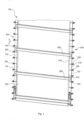
- Fig. 1 shows two door leaf segments 110 and 120 of a door leaf 100 of a roller shutter door arranged one behind the other in the door leaf movement direction indicated by the double arrow P.
- a stabilization device designed as a stabilization profile 200 is arranged between the door leaf segments 110 and 120.
- the stabilization profile 200 extends in a direction perpendicular to the direction of movement P of the door leaf, approximately in the plane of the door leaf.
- a lower edge of the upper door leaf segment 120 is in the area of an upper holder 230 (cf. Fig. 2 ) of the stabilizing profile 200, while an upper edge of the lower door leaf segment 110 is held in a lower receptacle 240 (cf. Fig. 2 ) of the stabilizing profile 200.
- An upper edge of the door leaf segment 120 is held on a further stabilizing profile 200, just as a lower edge of the door leaf segment 110 is also held on a lower stabilizing profile 200.
- the stabilizing profiles 200 are attached to a joint arrangement 300 that extends approximately parallel to the direction of movement of the door leaf or parallel to a lateral edge of the door leaf 100.
- the joint arrangement 300 comprises a plurality of joint members 310 that are arranged one behind the other in the direction of movement of the door leaf and are connected to one another in an articulated manner with respect to joint axes that run perpendicular to the direction of movement P of the door leaf.
- Three joint members 310 are arranged between two adjacent stabilizing profiles 200. In other embodiments, only one or two or four or more joint members can be provided between the stabilizing profiles 200.
- a stabilizing profile can also be provided in the area of each connection between successive joint members.
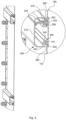
- the joint arrangement has guide rollers 320 on its side facing away from the door leaf segments 110 and 120, which are rotatably mounted with respect to roller axes running parallel to the joint axes.
- the guide rollers 320 are arranged in pairs in the area of a joint axis in such a way that they form a guide web between can be absorbed and can roll on opposite boundary surfaces of the guide bar in order to enable the door leaf movement to be guided as in the PCT/EP2019/058221 described.
- an upper edge region 112 of the door leaf segment 110 extending parallel to the joint axes and parallel to the stabilization profile 200 is arranged in a receptacle 240 of the stabilization profile 200.
- the upper edge 112 of the door leaf segment 110 is designed by bending the upper edge of the door leaf segment 112 onto itself as an extension in a door leaf plane perpendicular to the door leaf plane determined by the door leaf movement direction P and the stabilization profile 200. Starting from the extension 112, the door leaf segment 110 extends downwards with a transition region through an opening 250 of the stabilization profile 200 and is exposed outside the opening 250, as in Fig. 1 can be seen.
- the door leaf segment 120 also has an extension 122 accommodated in a receptacle 230 of the stabilizing profile 200. Starting from the extension 122, the door leaf segment 120 extends upwards with a transition region through an opening 225 and is exposed outside the opening 225.
- the mouth 250 is delimited by boundary surfaces 232 and 242, the distance between which in a direction parallel to the direction of the thickness of the door leaf is less than the thickness of the extension 112, but greater than the thickness of the transition region of the door leaf segment 110 between the extension 112 and the region exposed outside the stabilization profile 200.
- the mouth 225 is delimited by boundary surfaces 212 and 222, the distance between which in the direction of the thickness of the door leaf is less than the thickness of the extension 122, but greater than the thickness of a transition region between the extension 122 and the region of the door leaf segment 120 exposed outside the stabilization profile 200.
- the stabilizing profile 200 is made up of two parts 210 and 220 which are detachably connected to one another.
- the recess 240 at the lower edge of the stabilizing profile 200 is completely covered by the first stabilizing profile part 210 is formed, while the receptacle 230 is at the upper
- Edge of the stabilization profile 200 is formed by the two stabilization profile parts 210 and 220.
- a first boundary surface 212 of the mouth 225 is formed by the first stabilization profile part 210, while a second boundary surface 222 of the receptacle 230 is formed by the second stabilization profile part 220.
- an upper edge of a door leaf segment can be pushed into the receptacle 240 in a direction parallel to the stabilizing profile 200, with a transition region between the extension 240 and an area of the door leaf segment exposed outside the stabilizing profile 200 passing through the opening 250.
- the module prepared in this way can be threaded into a guide device, which can consist of a guide web arranged between the guide rollers 320.
- a lower edge 122 of the door leaf segment can be placed against a boundary surface 212 of the first stabilization profile part 210 and the second stabilization profile 220 can be clipped onto the first stabilization profile 210 to form the mouth 225, which is penetrated by the transition region between an extension of the door leaf segment received in the receptacle 230 and an area of the door leaf segment exposed outside the stabilization profile 200.
- the distance between the opposing boundary surfaces 212 and 222 or 232 and 242 of the mouths 225 and 250 is greater than the thickness of the transition areas passing through these mouths. This prevents a clamping effect in the area of the transition areas.
- the distance between the mouth 225 or 250 and the bottoms of the receptacles 230 and 240 opposite the corresponding mouths 225 or 250 is greater than the length of the extensions 122 or 112 in the direction of movement of the door leaf. This enables a relative movement of the door leaf segments 110 and 120 with respect to the stabilization profile 200.
- a sealing material can be arranged, which may swell if moisture penetrates.
- a damping element 230 is arranged between the bent lower edge of the disk 120 forming the extension 122 and the lower boundary surface of the part 220 of the stabilization profile 200, which on the one hand seals the disk 120 floatingly mounted in the stabilization profile 200 and on the other hand provides a preload of the disk 120 floatingly mounted in the stabilization profile 200, which helps to compensate for tolerances and holds the disk 120 tightly in its position.
- the damping element 140 reduces noise that can occur when the bent lower edge of the disk 120 is moved in the holder 230 and strikes the lower boundary surface of the part 220 of the stabilization profile.
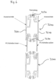
- the in Fig. 4 The embodiment of the invention shown differs essentially from that shown in the Figures 1 and 2 illustrated embodiment, that the door leaf segments have two panes 120a and 120b or 110a and 110b that run essentially parallel to one another, each of which is designed as flexible polycarbonate panes.
- the lower edges of the panes 120a and 120b are each equipped with an extension formed by bending these edges, which are mounted in a floating manner in receptacles 230a and 230b of the stabilizing profile 1200.
- the upper edges of the panes 110a and 110b of the lower segment are held in receptacles 240a and 240b of the stabilizing profile 1200.
- An air cushion 180 that promotes thermal insulation is formed between the panes 120a and 120b or 110a and 110b.
- the air cushion 180 is closed at the edges running parallel to the direction of movement P of the segments 120 and 110 by elastic pads 190 provided between the disks 120a and 120b or 110a and 110b.
- These pads 190 can be designed as elastic rungs.
- elastic pads made of a foam material can be used, which are glued in or mechanically fixed.
- the elastic design of the pads 190 also allows the necessary mobility when wrapping the door leaf into the spiral guide track when the opening position is reached.
- fan-shaped plastic elements which are connected to one another like hinges, can be clipped onto the pane in chamber 180. It is also possible to use corresponding elastic pads or elastic fan elements for door leaf segments with only one pane, as in Figure 1 and 2 shown are intended to compensate for the offset between the pane and the stabilizing profile in the wall area. This can improve the sealing of the door leaf in the closed position.
- the in Fig. 5 The embodiment of the invention shown differs essentially from that shown in the Fig. 4 explained embodiment that the chamber 2230b of the stabilizing profile 2200, which serves to accommodate the extension 230b at the lower edge of the disc 110b, has a greater depth in the direction of movement of the door leaf than the chamber 230a, which serves to accommodate the extension 122a formed at the lower edge of the disc 110a. This ensures that the disc 110b which is radially inward in the open position is mounted in the receptacle 230b with greater play than the disc 110a which is radially outward in the open position. This allows the different deformation of the discs 110a and 110b to be compensated when the door leaf reaches the open position, as in Fig. 5b ) is illustrated.
- the in Fig. 6 The embodiment of the invention shown differs essentially from that shown in the Fig. 5 explained embodiment of the invention that the stabilizing profiles 3200 are made of three parts in total, with the parts 3210, 3220, 3230 being made one after the other in the direction of the door leaf thickness.
- the part 3210 that is on the inside in the closed position of the door leaf, as well as the part 3220 of the stabilizing profile 3200 that is on the outside in the closed position, is made of a metallic material. This gives the stabilizing profile the necessary stability.
- the parts 3210 and 3220 are connected to one another via connecting elements 3230 made of thermally insulating material, such as plastic. This means that heat loss between the interior and exterior spaces can be effectively reduced via the 3200 stabilization profiles while ensuring sufficient overall stability of the 3200 stabilization profiles.
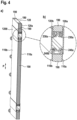
- a system for producing panes for the door leaf segments of roller doors according to the invention is shown schematically.
- a plastic sheet consisting at least partially of polycarbonate is continuously unwound as coil goods from an unwinder 510 in a conveying direction F.
- the plastic sheet passes through a trimming unit 520 in which the exact width of the plastic sheet is set and then a double-head profiling system 530 in which the edges of the plastic sheet running parallel to the conveying direction F are bent to create the extension of the panes.
- the profiling system has, as can be seen in Fig. 8, a large number of shaping rollers with which the edges of the material sheet are gradually bent.
- panes of a predetermined length are cut from the material sheet with the aid of a separating unit 540 along a separating line running perpendicular to the conveying direction F and placed on an outfeed table 550.
- the extensions in the area of the edges of the door leaf segments can also be formed by glued or welded piping.
- the stabilizing profiles 200 can be designed as a single piece, so that the extended edges of the door leaf segments have to be pushed laterally into the stabilizing profiles.
- guide arrangements can also be used in which guide rollers are accommodated in a guide rail.
- a contact-free magnetic guide can also be used.
Landscapes
- Engineering & Computer Science (AREA)
- Structural Engineering (AREA)
- Architecture (AREA)
- Civil Engineering (AREA)
- Mechanical Engineering (AREA)
- Securing Of Glass Panes Or The Like (AREA)
- Wing Frames And Configurations (AREA)
- Specific Sealing Or Ventilating Devices For Doors And Windows (AREA)
- Liquid Crystal (AREA)
- Window Of Vehicle (AREA)
- Pinball Game Machines (AREA)
- Lock And Its Accessories (AREA)
- Power-Operated Mechanisms For Wings (AREA)
Priority Applications (1)
| Application Number | Priority Date | Filing Date | Title |
|---|---|---|---|
| HRP20241793TT HRP20241793T1 (hr) | 2019-09-19 | 2020-05-26 | Roletna vrata |
Applications Claiming Priority (3)
| Application Number | Priority Date | Filing Date | Title |
|---|---|---|---|
| DE102019125204.0A DE102019125204A1 (de) | 2019-09-19 | 2019-09-19 | Rolltor |
| PCT/EP2020/064500 WO2021052637A1 (de) | 2019-09-19 | 2020-05-26 | Rolltor |
| EP20729666.6A EP4031740B1 (de) | 2019-09-19 | 2020-05-26 | Rolltor |
Related Parent Applications (2)
| Application Number | Title | Priority Date | Filing Date |
|---|---|---|---|
| EP20729666.6A Division-Into EP4031740B1 (de) | 2019-09-19 | 2020-05-26 | Rolltor |
| EP20729666.6A Division EP4031740B1 (de) | 2019-09-19 | 2020-05-26 | Rolltor |
Publications (4)
| Publication Number | Publication Date |
|---|---|
| EP4234875A2 EP4234875A2 (de) | 2023-08-30 |
| EP4234875A3 EP4234875A3 (de) | 2023-12-06 |
| EP4234875C0 EP4234875C0 (de) | 2024-11-27 |
| EP4234875B1 true EP4234875B1 (de) | 2024-11-27 |
Family
ID=70922008
Family Applications (2)
| Application Number | Title | Priority Date | Filing Date |
|---|---|---|---|
| EP23172738.9A Active EP4234875B1 (de) | 2019-09-19 | 2020-05-26 | Rolltor |
| EP20729666.6A Active EP4031740B1 (de) | 2019-09-19 | 2020-05-26 | Rolltor |
Family Applications After (1)
| Application Number | Title | Priority Date | Filing Date |
|---|---|---|---|
| EP20729666.6A Active EP4031740B1 (de) | 2019-09-19 | 2020-05-26 | Rolltor |
Country Status (15)
| Country | Link |
|---|---|
| US (1) | US20220298848A1 (pl) |
| EP (2) | EP4234875B1 (pl) |
| JP (1) | JP7556581B2 (pl) |
| CN (1) | CN114375362B (pl) |
| CA (1) | CA3148339C (pl) |
| DE (1) | DE102019125204A1 (pl) |
| DK (1) | DK4031740T3 (pl) |
| ES (2) | ES2950982T3 (pl) |
| FI (1) | FI4031740T3 (pl) |
| HR (2) | HRP20241793T1 (pl) |
| HU (2) | HUE062755T2 (pl) |
| PL (2) | PL4031740T3 (pl) |
| PT (1) | PT4031740T (pl) |
| SI (1) | SI4031740T1 (pl) |
| WO (1) | WO2021052637A1 (pl) |
Families Citing this family (3)
| Publication number | Priority date | Publication date | Assignee | Title |
|---|---|---|---|---|
| SI3805513T1 (sl) * | 2017-05-31 | 2023-10-30 | Seuster Kg | Navijalna vrata |
| DE102021105368A1 (de) * | 2021-03-05 | 2022-09-08 | Seuster Kg | Tor |
| US20240060356A1 (en) * | 2022-08-16 | 2024-02-22 | Overhead Door Corporation | Modular barrier panel frame reinforcement systems and methods |
Family Cites Families (55)
| Publication number | Priority date | Publication date | Assignee | Title |
|---|---|---|---|---|
| US1017808A (en) * | 1908-03-04 | 1912-02-20 | Albert Rush | Flexible fire-resisting shutter. |
| DE800786C (de) * | 1949-07-20 | 1950-12-07 | Ludwig Mausberg | Rolladen aus Metall |
| US4345635A (en) * | 1980-08-29 | 1982-08-24 | Solomon Martin D | Rolling protective gate for store fronts or the like |
| DE3210560A1 (de) * | 1982-03-23 | 1983-10-06 | Hans Ammann | Rolladen |
| US4972894A (en) * | 1987-09-12 | 1990-11-27 | Rolf Machill | Roller curtain |
| US5564164A (en) * | 1988-08-25 | 1996-10-15 | Jell+E,Acu A+Ee ; John F. | Sectional door panel hinge |
| NO169858C (no) * | 1989-03-02 | 1992-08-12 | Roger Sten Snarli | Innretning ved rulle- eller foldesjalusi |
| US5484007A (en) * | 1990-05-11 | 1996-01-16 | Rejc; Gabrijel | Vertical lift gate with strip cladding in guideways |
| DE4015216A1 (de) * | 1990-05-11 | 1991-11-14 | Efaflex Transport Lager | Abschlusselement fuer eine oeffnung |
| JP2536642Y2 (ja) * | 1990-07-17 | 1997-05-21 | 三和シヤッター工業株式会社 | シャッタースラットの接続部の構造 |
| GB2252781B (en) * | 1991-02-14 | 1994-08-17 | Sanwa Shutter Corp | Architectural shutter curtain device |
| US5332021A (en) * | 1991-09-11 | 1994-07-26 | Todd John M | Flexible retractable door |
| US5474118A (en) * | 1994-05-31 | 1995-12-12 | Hoffman; Robert E. | Reinforced roll-type shuttters |
| CA2147199A1 (en) * | 1995-04-18 | 1996-10-19 | Vittorio De Zen | Extruded hinge members and folding doors formed therefrom |
| US5794678A (en) * | 1996-02-22 | 1998-08-18 | Rite-Hite Corporation | Sealing system for a roller door |
| ATE184957T1 (de) * | 1996-07-31 | 1999-10-15 | Ceraper S L | Motorgetriebener umkehrbarer rolladen |
| EP0998617B1 (en) * | 1997-07-25 | 2004-04-28 | Rytec Corporation | Improved overhead rigid-panel door |
| DE19737534A1 (de) * | 1997-08-28 | 1999-03-04 | Schanz Hans | Rolladenpanzer |
| CN2312316Y (zh) * | 1997-12-17 | 1999-03-31 | 黎文志 | 店铺门窗的卷帘 |
| DE19757729B4 (de) * | 1997-12-23 | 2004-09-16 | Eitec Führungsbahnschutz-Systeme Gmbh | Gliederschürze |
| EP0936339B1 (de) * | 1998-02-10 | 2004-04-28 | Firma Wilhelm Hotz | Rollgitter- oder Rolltoranordnung mit aufrollbarer Tür |
| FR2781249A1 (fr) * | 1998-07-15 | 2000-01-21 | Ecran System | Dispositif pour l'articulation de lames |
| JP3416541B2 (ja) | 1998-12-04 | 2003-06-16 | 文化シヤッター株式会社 | 開閉装置の開閉体取付方法 |
| US6672362B1 (en) * | 2000-11-10 | 2004-01-06 | Wayne-Dalton Corp. | Upward acting sectional door |
| DE10119242A1 (de) * | 2001-04-19 | 2002-10-31 | Efaflex Tor & Sicherheitssys | Industrietor, Lamelle für ein Industrietor sowie Verfahren zur Herstellung einer derartigen Lamelle |
| JP3950761B2 (ja) * | 2001-08-23 | 2007-08-01 | アイセル株式会社 | シャッタ |
| FR2832137B1 (fr) * | 2001-11-09 | 2004-10-08 | Vaslin Bucher | Dispositif de porte, pressoir equipe d'une telle porte et procede de fabrication |
| DE10236648B4 (de) * | 2002-08-09 | 2011-11-17 | Efaflex Tor- Und Sicherheitssysteme Gmbh & Co. Kg | Schnellaufendes Industrietor mit flexiblem Behang |
| DE10342302A1 (de) * | 2003-09-12 | 2005-04-14 | Petra Rejc | Rolltor mit Kollisionsschutz |
| SG110075A1 (en) * | 2003-10-06 | 2005-04-28 | Lok Yung Wong | Improvements to roller shutters |
| US7357171B2 (en) * | 2004-03-17 | 2008-04-15 | Qmi Security Solutions | Low-clearance shutter slat |
| EP1643071A1 (en) * | 2004-09-29 | 2006-04-05 | Cardo Door Ab | Sliding door comprising a section joint profile and method of making a sliding door |
| US20070012409A1 (en) * | 2005-07-12 | 2007-01-18 | Yehezkel Twina | Rolling shutters |
| US20070137802A1 (en) * | 2005-12-20 | 2007-06-21 | Lukasik David W | Protective shutter panel |
| US7748431B2 (en) * | 2006-06-05 | 2010-07-06 | Rite-Hite Holding Corporation | Track and guide system for a door |
| DE202006017619U1 (de) * | 2006-11-20 | 2007-03-29 | Adolf Seuster Gmbh & Co. Kg | Rolltor |
| NZ581082A (en) * | 2007-05-16 | 2012-07-27 | Insite Mfg Pty Ltd | Security panel with formed end edges for interlocking with a channelled frame and roll forming method |
| DE102008007592A1 (de) * | 2008-02-06 | 2009-08-13 | Efaflex Tor- Und Sicherheitssysteme Gmbh & Co. Kg | Hubtoranordnung sowie Torsturz-Abdichteinrichtung hierfür |
| DE102008023511A1 (de) * | 2008-05-15 | 2009-11-19 | Efaflex Tor- Und Sicherheitssysteme Gmbh & Co. Kg | Verschlusseinrichtung in Form einer Tür oder eines Tores oder einer Schleuse oder einer Abdeckung oder dergleichen |
| FR2945313B1 (fr) * | 2009-05-07 | 2011-04-22 | Profilmar | Rideau de securite transparent |
| US8365801B1 (en) * | 2009-07-23 | 2013-02-05 | Motosko Stephen J | Roll-up/down storm shutter having corrugated shutter slats |
| DE102011052304A1 (de) * | 2011-07-29 | 2013-01-31 | Efaflex Inzeniring D.O.O. | Hubtor mit einer beweglichen Torblattführung |
| US8746321B2 (en) * | 2011-08-31 | 2014-06-10 | Qualitas Manufacturing, Inc. | Base slat retention and motor triggering for rolling protective shutters |
| FR2992994B1 (fr) * | 2012-07-04 | 2017-09-22 | Guy Meyere | Rideau roulant transparent |
| JP6549093B2 (ja) * | 2013-03-15 | 2019-07-24 | ハンター ダグラス インコーポレイテッド | 建築物開口部の巻き上げ式の覆いならびに関連する方法、システムおよび装置 |
| US9382752B1 (en) * | 2014-03-19 | 2016-07-05 | Kenneth Zubay | Vertical roll down device weight bar containing a self-adjusting bottom barrier blade for variable pitched or contoured surfaces |
| DE102014005578A1 (de) * | 2014-04-15 | 2015-10-15 | Seuster Kg | Tor |
| EP3263819B1 (de) * | 2016-06-28 | 2018-12-19 | Gabrijel Rejc | Vertikal bewegbares tor mit einem torblatt |
| SI3263820T1 (sl) * | 2016-06-28 | 2019-02-28 | Gabrijel Rejc | Motorno gnana in navpično premična dvižna vrata |
| SI3805513T1 (sl) * | 2017-05-31 | 2023-10-30 | Seuster Kg | Navijalna vrata |
| ES2952747T3 (es) * | 2018-04-05 | 2023-11-03 | Seuster Kg | Puerta con disposición de guiado |
| DE102018121853A1 (de) * | 2018-09-07 | 2020-03-12 | Thodacon Werkzeugmaschinenschutz Gmbh | Abdeckvorrichtung |
| SG10201905150PA (en) * | 2019-06-06 | 2021-01-28 | Gliderol Doors S Pte Ltd | Roller shutter for mitigating impact force |
| DE102021105368A1 (de) * | 2021-03-05 | 2022-09-08 | Seuster Kg | Tor |
| DE102021119696A1 (de) * | 2021-07-29 | 2023-02-02 | Seuster Kg | Tor |
-
2019
- 2019-09-19 DE DE102019125204.0A patent/DE102019125204A1/de active Pending
-
2020
- 2020-05-26 SI SI202030279T patent/SI4031740T1/sl unknown
- 2020-05-26 PT PT207296666T patent/PT4031740T/pt unknown
- 2020-05-26 HR HRP20241793TT patent/HRP20241793T1/hr unknown
- 2020-05-26 HU HUE20729666A patent/HUE062755T2/hu unknown
- 2020-05-26 EP EP23172738.9A patent/EP4234875B1/de active Active
- 2020-05-26 HU HUE23172738A patent/HUE070107T2/hu unknown
- 2020-05-26 EP EP20729666.6A patent/EP4031740B1/de active Active
- 2020-05-26 CN CN202080063869.4A patent/CN114375362B/zh active Active
- 2020-05-26 HR HRP20230877TT patent/HRP20230877T1/hr unknown
- 2020-05-26 PL PL20729666.6T patent/PL4031740T3/pl unknown
- 2020-05-26 WO PCT/EP2020/064500 patent/WO2021052637A1/de not_active Ceased
- 2020-05-26 JP JP2022505275A patent/JP7556581B2/ja active Active
- 2020-05-26 FI FIEP20729666.6T patent/FI4031740T3/fi active
- 2020-05-26 DK DK20729666.6T patent/DK4031740T3/da active
- 2020-05-26 US US17/642,183 patent/US20220298848A1/en active Pending
- 2020-05-26 PL PL23172738.9T patent/PL4234875T3/pl unknown
- 2020-05-26 CA CA3148339A patent/CA3148339C/en active Active
- 2020-05-26 ES ES20729666T patent/ES2950982T3/es active Active
- 2020-05-26 ES ES23172738T patent/ES2997939T3/es active Active
Also Published As
| Publication number | Publication date |
|---|---|
| PL4234875T3 (pl) | 2025-03-31 |
| EP4031740B1 (de) | 2023-07-05 |
| CN114375362B (zh) | 2023-09-22 |
| EP4234875C0 (de) | 2024-11-27 |
| ES2950982T3 (es) | 2023-10-17 |
| CA3148339A1 (en) | 2021-03-25 |
| DK4031740T3 (da) | 2023-08-07 |
| CN114375362A (zh) | 2022-04-19 |
| CA3148339C (en) | 2023-11-28 |
| PL4031740T3 (pl) | 2023-11-27 |
| EP4234875A3 (de) | 2023-12-06 |
| JP2022549059A (ja) | 2022-11-24 |
| HUE070107T2 (hu) | 2025-05-28 |
| JP7556581B2 (ja) | 2024-09-26 |
| WO2021052637A1 (de) | 2021-03-25 |
| ES2997939T3 (en) | 2025-02-18 |
| FI4031740T3 (fi) | 2023-09-26 |
| SI4031740T1 (sl) | 2023-12-29 |
| HRP20230877T1 (hr) | 2023-11-10 |
| US20220298848A1 (en) | 2022-09-22 |
| HRP20241793T1 (hr) | 2025-03-14 |
| DE102019125204A1 (de) | 2021-03-25 |
| PT4031740T (pt) | 2023-07-20 |
| EP4031740A1 (de) | 2022-07-27 |
| HUE062755T2 (hu) | 2023-12-28 |
| EP4234875A2 (de) | 2023-08-30 |
Similar Documents
| Publication | Publication Date | Title |
|---|---|---|
| DE19758648C2 (de) | Crashschutzvorrichtung für Schnellaufrolltore sowie Schnellaufrolltor | |
| EP3805513B1 (de) | Rolltor | |
| EP4234875B1 (de) | Rolltor | |
| EP3176355B1 (de) | Rolltor | |
| WO1991018178A1 (de) | Hubtor mit einem lamellenpanzer mit abwinkelbaren lamellen | |
| EP2136025B2 (de) | Tor | |
| EP1527248A1 (de) | Schnellaufendes industrietor mit flexiblem behang | |
| EP1498382B1 (de) | Türkämpfer für Aufzug | |
| EP1354545B1 (de) | Dichtung für eine Duschabtrennung | |
| EP0370324A2 (de) | Torblatt | |
| DE10119240A1 (de) | Industrietor, doppelwandige Lamelle für ein Industrietor sowie Verfahren zur Herstellung einer derartigen Lamelle | |
| DE19949329C2 (de) | Schnellauftor | |
| EP4301954B1 (de) | Tor mit einer funktionsfolie | |
| DE10210247A1 (de) | Schnellauftor | |
| DE102017117020A1 (de) | Sektionaltorblatt und Sektionaltor mit Sektionaltorblatt | |
| DE202020101025U1 (de) | Torblatt und Tor | |
| DE102020103603B4 (de) | Hochwasserbeständiges Sektionaltor | |
| DE202011050625U1 (de) | Kettenantrieb | |
| DE102010052160A1 (de) | Wärmeisoliertes Tor | |
| DE102005037284B4 (de) | Verfahren zum Herstellen einer Führungsschienenanordnung und mit dem Verfahren hergestellte Führungsschienenanordnung | |
| EP0480290A1 (de) | Torblatt eines Sektional- oder Falttors, insbesondere für Garagen oder Hallen, mit Aussteifungsprofilen | |
| DE202020100179U1 (de) | Sektionaltorblatt | |
| EP4685323A1 (de) | Abgedichteter antrieb für türsystem eines fahrzeugs und verfahren zum öffnen und schliessen eines linear verschiebbaren flügels mit dem abgedichteten antrieb | |
| WO2004029396A1 (de) | Schnellauftor | |
| DE102009027240A1 (de) | Flügel und Verfahren zur Montage eines Flügels |
Legal Events
| Date | Code | Title | Description |
|---|---|---|---|
| REG | Reference to a national code |
Ref country code: HR Ref legal event code: TUEP Ref document number: P20241793T Country of ref document: HR |
|
| PUAI | Public reference made under article 153(3) epc to a published international application that has entered the european phase |
Free format text: ORIGINAL CODE: 0009012 |
|
| STAA | Information on the status of an ep patent application or granted ep patent |
Free format text: STATUS: REQUEST FOR EXAMINATION WAS MADE |
|
| 17P | Request for examination filed |
Effective date: 20230511 |
|
| AC | Divisional application: reference to earlier application |
Ref document number: 4031740 Country of ref document: EP Kind code of ref document: P |
|
| AK | Designated contracting states |
Kind code of ref document: A2 Designated state(s): AL AT BE BG CH CY CZ DE DK EE ES FI FR GB GR HR HU IE IS IT LI LT LU LV MC MK MT NL NO PL PT RO RS SE SI SK SM TR |
|
| PUAL | Search report despatched |
Free format text: ORIGINAL CODE: 0009013 |
|
| AK | Designated contracting states |
Kind code of ref document: A3 Designated state(s): AL AT BE BG CH CY CZ DE DK EE ES FI FR GB GR HR HU IE IS IT LI LT LU LV MC MK MT NL NO PL PT RO RS SE SI SK SM TR |
|
| RIC1 | Information provided on ipc code assigned before grant |
Ipc: E06B 3/70 20060101ALI20231031BHEP Ipc: B29C 53/04 20060101ALI20231031BHEP Ipc: E06B 3/48 20060101ALI20231031BHEP Ipc: E06B 9/165 20060101ALI20231031BHEP Ipc: E06B 9/15 20060101ALI20231031BHEP Ipc: E06B 9/11 20060101AFI20231031BHEP |
|
| GRAP | Despatch of communication of intention to grant a patent |
Free format text: ORIGINAL CODE: EPIDOSNIGR1 |
|
| STAA | Information on the status of an ep patent application or granted ep patent |
Free format text: STATUS: GRANT OF PATENT IS INTENDED |
|
| INTG | Intention to grant announced |
Effective date: 20240701 |
|
| GRAS | Grant fee paid |
Free format text: ORIGINAL CODE: EPIDOSNIGR3 |
|
| GRAA | (expected) grant |
Free format text: ORIGINAL CODE: 0009210 |
|
| STAA | Information on the status of an ep patent application or granted ep patent |
Free format text: STATUS: THE PATENT HAS BEEN GRANTED |
|
| AC | Divisional application: reference to earlier application |
Ref document number: 4031740 Country of ref document: EP Kind code of ref document: P |
|
| AK | Designated contracting states |
Kind code of ref document: B1 Designated state(s): AL AT BE BG CH CY CZ DE DK EE ES FI FR GB GR HR HU IE IS IT LI LT LU LV MC MK MT NL NO PL PT RO RS SE SI SK SM TR |
|
| REG | Reference to a national code |
Ref country code: GB Ref legal event code: FG4D Free format text: NOT ENGLISH |
|
| REG | Reference to a national code |
Ref country code: CH Ref legal event code: EP |
|
| REG | Reference to a national code |
Ref country code: DE Ref legal event code: R096 Ref document number: 502020009871 Country of ref document: DE |
|
| REG | Reference to a national code |
Ref country code: IE Ref legal event code: FG4D Free format text: LANGUAGE OF EP DOCUMENT: GERMAN |
|
| U01 | Request for unitary effect filed |
Effective date: 20241127 |
|
| U07 | Unitary effect registered |
Designated state(s): AT BE BG DE DK EE FI FR IT LT LU LV MT NL PT RO SE SI Effective date: 20241204 |
|
| REG | Reference to a national code |
Ref country code: ES Ref legal event code: FG2A Ref document number: 2997939 Country of ref document: ES Kind code of ref document: T3 Effective date: 20250218 |
|
| REG | Reference to a national code |
Ref country code: SK Ref legal event code: T3 Ref document number: E 45820 Country of ref document: SK |
|
| REG | Reference to a national code |
Ref country code: HR Ref legal event code: T1PR Ref document number: P20241793 Country of ref document: HR |
|
| PG25 | Lapsed in a contracting state [announced via postgrant information from national office to epo] |
Ref country code: IS Free format text: LAPSE BECAUSE OF FAILURE TO SUBMIT A TRANSLATION OF THE DESCRIPTION OR TO PAY THE FEE WITHIN THE PRESCRIBED TIME-LIMIT Effective date: 20250327 |
|
| PG25 | Lapsed in a contracting state [announced via postgrant information from national office to epo] |
Ref country code: RS Free format text: LAPSE BECAUSE OF FAILURE TO SUBMIT A TRANSLATION OF THE DESCRIPTION OR TO PAY THE FEE WITHIN THE PRESCRIBED TIME-LIMIT Effective date: 20250227 |
|
| REG | Reference to a national code |
Ref country code: GR Ref legal event code: EP Ref document number: 20250400394 Country of ref document: GR Effective date: 20250409 |
|
| REG | Reference to a national code |
Ref country code: HU Ref legal event code: AG4A Ref document number: E070107 Country of ref document: HU |
|
| REG | Reference to a national code |
Ref country code: HR Ref legal event code: ODRP Ref document number: P20241793 Country of ref document: HR Payment date: 20250516 Year of fee payment: 6 |
|
| U20 | Renewal fee for the european patent with unitary effect paid |
Year of fee payment: 6 Effective date: 20250516 |
|
| PG25 | Lapsed in a contracting state [announced via postgrant information from national office to epo] |
Ref country code: SM Free format text: LAPSE BECAUSE OF FAILURE TO SUBMIT A TRANSLATION OF THE DESCRIPTION OR TO PAY THE FEE WITHIN THE PRESCRIBED TIME-LIMIT Effective date: 20241127 |
|
| PGFP | Annual fee paid to national office [announced via postgrant information from national office to epo] |
Ref country code: PL Payment date: 20250514 Year of fee payment: 6 |
|
| PGFP | Annual fee paid to national office [announced via postgrant information from national office to epo] |
Ref country code: GB Payment date: 20250522 Year of fee payment: 6 Ref country code: ES Payment date: 20250616 Year of fee payment: 6 |
|
| PGFP | Annual fee paid to national office [announced via postgrant information from national office to epo] |
Ref country code: HU Payment date: 20250519 Year of fee payment: 6 Ref country code: NO Payment date: 20250520 Year of fee payment: 6 |
|
| PGFP | Annual fee paid to national office [announced via postgrant information from national office to epo] |
Ref country code: HR Payment date: 20250516 Year of fee payment: 6 |
|
| PGFP | Annual fee paid to national office [announced via postgrant information from national office to epo] |
Ref country code: GR Payment date: 20250519 Year of fee payment: 6 |
|
| PGFP | Annual fee paid to national office [announced via postgrant information from national office to epo] |
Ref country code: CH Payment date: 20250601 Year of fee payment: 6 |
|
| PGFP | Annual fee paid to national office [announced via postgrant information from national office to epo] |
Ref country code: TR Payment date: 20250516 Year of fee payment: 6 Ref country code: SK Payment date: 20250520 Year of fee payment: 6 |
|
| PGFP | Annual fee paid to national office [announced via postgrant information from national office to epo] |
Ref country code: CZ Payment date: 20250514 Year of fee payment: 6 |
|
| PGFP | Annual fee paid to national office [announced via postgrant information from national office to epo] |
Ref country code: IE Payment date: 20250522 Year of fee payment: 6 |
|
| PLBE | No opposition filed within time limit |
Free format text: ORIGINAL CODE: 0009261 |
|
| STAA | Information on the status of an ep patent application or granted ep patent |
Free format text: STATUS: NO OPPOSITION FILED WITHIN TIME LIMIT |
|
| 26N | No opposition filed |
Effective date: 20250828 |
|
| PG25 | Lapsed in a contracting state [announced via postgrant information from national office to epo] |
Ref country code: MC Free format text: LAPSE BECAUSE OF FAILURE TO SUBMIT A TRANSLATION OF THE DESCRIPTION OR TO PAY THE FEE WITHIN THE PRESCRIBED TIME-LIMIT Effective date: 20241127 |