EP4234094B1 - Buse d'application - Google Patents
Buse d'application Download PDFInfo
- Publication number
- EP4234094B1 EP4234094B1 EP23172475.8A EP23172475A EP4234094B1 EP 4234094 B1 EP4234094 B1 EP 4234094B1 EP 23172475 A EP23172475 A EP 23172475A EP 4234094 B1 EP4234094 B1 EP 4234094B1
- Authority
- EP
- European Patent Office
- Prior art keywords
- nozzle
- application
- section
- spatial direction
- clamping plates
- Prior art date
- Legal status (The legal status is an assumption and is not a legal conclusion. Google has not performed a legal analysis and makes no representation as to the accuracy of the status listed.)
- Active
Links
Images


Classifications
-
- B—PERFORMING OPERATIONS; TRANSPORTING
- B05—SPRAYING OR ATOMISING IN GENERAL; APPLYING FLUENT MATERIALS TO SURFACES, IN GENERAL
- B05B—SPRAYING APPARATUS; ATOMISING APPARATUS; NOZZLES
- B05B1/00—Nozzles, spray heads or other outlets, with or without auxiliary devices such as valves, heating means
- B05B1/02—Nozzles, spray heads or other outlets, with or without auxiliary devices such as valves, heating means designed to produce a jet, spray, or other discharge of particular shape or nature, e.g. in single drops, or having an outlet of particular shape
- B05B1/04—Nozzles, spray heads or other outlets, with or without auxiliary devices such as valves, heating means designed to produce a jet, spray, or other discharge of particular shape or nature, e.g. in single drops, or having an outlet of particular shape in flat form, e.g. fan-like, sheet-like
- B05B1/044—Slits, e.g. narrow openings defined by two straight and parallel lips; Elongated outlets for producing very wide discharges, e.g. fluid curtains
-
- B—PERFORMING OPERATIONS; TRANSPORTING
- B05—SPRAYING OR ATOMISING IN GENERAL; APPLYING FLUENT MATERIALS TO SURFACES, IN GENERAL
- B05C—APPARATUS FOR APPLYING FLUENT MATERIALS TO SURFACES, IN GENERAL
- B05C5/00—Apparatus in which liquid or other fluent material is projected, poured or allowed to flow on to the surface of the work
- B05C5/02—Apparatus in which liquid or other fluent material is projected, poured or allowed to flow on to the surface of the work the liquid or other fluent material being discharged through an outlet orifice by pressure, e.g. from an outlet device in contact or almost in contact, with the work
- B05C5/0254—Coating heads with slot-shaped outlet
Definitions
- the invention relates to an application nozzle for applying a viscous material to workpieces according to the preamble of claim 1.
- the invention also relates to a method for producing nozzle plates for an application nozzle according to claim 15.
- Such application nozzles also called flatstream nozzles, are used to generate a wide spray jet, for example for applying a paint for seam sealing or an insulating material that must be applied flatly to a workpiece.
- Such application nozzles are used in particular for coating body components for the automotive industry, but also for coating components of other devices such as built-in appliances for kitchens.
- the application channel widens towards the material outlet in a first spatial direction in which the width of the application nozzle is measured, which is usually several times (for example 5 to 10 times) larger than the thickness of the nozzle body measured in a second spatial direction perpendicular to the first spatial direction.
- This can be accompanied by a narrowing of the application channel in the second spatial direction, both in the application nozzles according to the prior art and in the application nozzle according to the invention.
- the nozzle body is mounted on a nozzle holder, through which a feed channel extends, via which the material is fed into the application channel.
- the nozzle body is detachably fixed to the nozzle holder, whereby the nozzle holder in previously known application nozzles has two clamping plates which rest against opposite side surfaces of the nozzle body and clamp it in a space formed between them.
- a clamping plate is integral with the feed channel.
- the other clamping plate is detachably attached to the base body of the nozzle holder and to the nozzle body.
- the invention is based on the idea that by designing the two clamping plates as separate components and releasably fixing them to the base body and the nozzle body, the edges that delimit the gap between the clamping plates intended to accommodate the nozzle body can be designed as sharp edges with a small radius so that the nozzle body can be fitted well between the clamping plates and a high degree of tightness is achieved at the transition from the base body to the nozzle body.
- the tightness is further improved if, according to the invention, the side surfaces of the nozzle body are inclined towards one another at an acute angle starting from the base body, this angle preferably being a maximum of 30° and in particular a maximum of 10°. Because the clamping surfaces of the clamping plates that are in contact with the side surfaces are inclined at the same angle starting from the base body. If the nozzles run at an angle to each other, they press the nozzle body against the base body when it is clamped.
- the side surfaces each extend to an end region which protrudes from the space between the two clamping parts and has the material outlet, where the thickness of the nozzle body increases.
- a greater thickness of the nozzle body in the area of the material outlet increases its stability, so that it is more mechanically resistant to mechanical stresses, such as during cleaning.
- the end region can be designed as a shoulder protruding from the side surfaces on both sides.
- the clamping plates each have a clamping surface that lies flat against one of the side surfaces of the nozzle body. This achieves a good clamping effect. It is also preferred that the clamping plates each have a groove in which a part of the base body is accommodated. This makes it easier to position the clamping plates in relation to the base body.
- the clamping plates and the nozzle body are expediently fixed to one another by means of at least one screw and/or at least one pin. This represents a particularly simple type of fastening.
- the nozzle body is preferably made of hard metal.
- Hard metal is a metal matrix composite material in which hard materials in particle form are held together by a metal matrix.
- Hard materials used are in particular metal carbides or metal nitrides, such as tungsten carbide, titanium carbide, titanium nitride, niobium carbide, tantalum carbide or vanadium carbide.
- Hard metal is a more expensive material than metal. However, it is much more durable and less prone to wear, especially with regard to abrasive viscous materials.
- the nozzle body has two nozzle plates lying flat against one another, between which at least a section of the application channel is located.
- the nozzle plates are advantageously located loosely against each other and are pressed against each other by means of the clamping plates. It is possible for one of the nozzle plates to have a recess forming the application channel, while the other nozzle plate is ground flat and the recess only covers the application channel on one side. It is preferred, however, that both nozzle plates are of the same construction.
- each of the nozzle plates has, on the side facing the other nozzle plate, a boundary surface that at least partially limits the application channel, a shoulder protruding from the boundary surface with a first contact surface that rests on the other nozzle plate and is parallel to the boundary surface, and a second contact surface that adjoins the boundary surface and is flush with the boundary surface and against which the first contact surface of the other nozzle plate rests.
- This solution according to the invention according to the independent claim 10 offers the advantage that the nozzle body is easier to manufacture, particularly when it is made of hard metal. It is preferred that the nozzle plates rest against each other on contact surfaces to which the second spatial direction extends transversely and preferably perpendicularly.
- the nozzle plates are advantageously made in one piece and preferably from hard metal.
- the application channel has a first section extending from the material inlet and delimited on two sides by the clamping plates, and a second section extending to the material outlet and surrounded by the nozzle body.
- the application channel it is possible for the application channel to widen in the first spatial direction only in its second section.
- the first section also widens in the first spatial direction starting from the material inlet towards the second section.
- the nozzle plates can simply be made from hard metal plates. In each case, a cutout is cut out of the hard metal plate by means of erosion or cutting to form the first section of the application channel, and then the boundary surface and the second contact surface are produced by grinding along an edge delimiting the shoulder. Only the Contact surfaces and the surfaces delimiting the application channel are ground, while grinding of the opposite side surfaces of the nozzle body can be omitted.
- sealing it is possible for sealing to be achieved by sealing the nozzle body against the nozzle holder.
- first section and an end section of the feed channel that opens into the first section at the material inlet may be at least partially lined by a sealing element that rests against the base body and the clamping plates in order to improve the sealing effect.
- the sealing element is made in one piece from a thermoplastic material, preferably from polyoxymethylene (POM) or polytetrafluoroethylene (PTFE).
- POM polyoxymethylene
- PTFE polytetrafluoroethylene
- the sealing element advantageously has an outlet gap that opens into the second section, the width of which, measured in the first spatial direction, is several times greater than its thickness measured in the second spatial direction.
- the thickness of the outlet gap is expediently a maximum of twice as large as the thickness of the second section measured in the second spatial direction and is preferably approximately the same size in the sense that it differs from the thickness of the second section by a maximum of 10%.
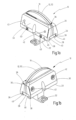
- the application nozzle 10 shown in the drawing according to the first embodiment has a nozzle body 12 through which an application channel 14 for viscous material extends from a material inlet 16 to a material outlet 18.
- the nozzle body 12 is detachably mounted on a nozzle holder 20 which has a base body 22 through which a feed channel 24 for the viscous material extends to a feed opening 26.
- the nozzle body 12 sits on a surface 28 of the base body 22 in which the feed opening 26 is located, the feed opening 26 communicating with the material inlet 16 such that the feed channel 24 opens into the application channel 14 at the feed opening 26.
- the nozzle holder 20 further comprises two clamping plates 30, the clamping surfaces 32 facing each other rest against side surfaces 34 of the nozzle body 12 facing away from each other and clamp the nozzle body 12 in a gap 36 between the clamping plates 30.
- each of the clamping plates 30 comprises a groove 38 in which a section 40 of the base body 22 is received, which is limited at the top by the surface 28.
- Screw openings 42 extend through the nozzle body 12 and the clamping plates 30, through which screws are passed, with which the clamping plates 30 are clamped to the nozzle body 12, so that the clamping surfaces 32 are pressed against the side surfaces 34.
- Further screws 43 fix the Fig. 1a clamping plate 30 facing the viewer on the base body 22, while a cylindrical pin 45 is also Fig. 1a clamping plate 30 facing the viewer, and the base body 22 and into a blind hole in the Fig. 1a clamping plate 30 facing away from the viewer.
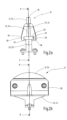
- the nozzle body 12 has a width b in a first spatial direction 44 parallel to the side surfaces 34, which is significantly greater than its thickness d, which is measured in a second spatial direction 46 perpendicular to the first spatial direction 44.
- the application channel 14 has a first section 48 extending from the material inlet 16, which is open towards the side surfaces 34 and is sealed on both sides by the clamping surfaces 32.
- the first section 48 is followed by a second section 50 of the application channel 14, which extends to the material outlet 18. Both sections 48, 50 of the application channel 14 widen towards the material outlet 18 in the first spatial direction 44, as can be seen in particular in Fig. 3a shown.
- the expansion takes place with a constant opening angle, starting almost from the material inlet 16.
- the two side surfaces 34 also do not run parallel to one another, but rather towards one another at an acute angle of approximately 8° starting from the base body 22.
- the edges of all components can be precisely ground so that they can be precisely joined to the nozzle body 12.
- a thickened end region 52 of the nozzle body 12 protrudes upwards from the intermediate space 36, facing away from the base body 22.
- the material outlet 18 is located in this end region 52.
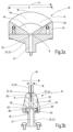
- the nozzle body 12 is composed of two identical nozzle plates 54, each of which is made in one piece from hard metal ( Fig. 4a to 4c ).
- Each of the nozzle plates 54 is made from a plate-shaped blank made of hard metal.
- an open-edged cutout 56 partially forming the material inlet 16 and the first section 48 of the application channel 14 is formed by means of erosion or cutting into the blank.
- the blank is then ground along an edge 58 on one side so that a shoulder 60 remains.
- the shoulder 60 has a first contact surface 62.
- the shoulder 60 is followed by a boundary surface 64 which runs parallel to the first contact surface 62 and delimits the second section 50 of the application channel 14 on one side.
- boundary surface 64 is followed by a second contact surface 66 which is coplanar with it.
- Two identical nozzle plates 44 are placed loosely against one another to form the nozzle body 12, with the first contact surface 62 of one nozzle plate 54 lying flat against the second contact surface 66 of the other nozzle plate 54 and vice versa.
- the second section 50 of the application channel 14 is then located between the two boundary surfaces 64.
- the nozzle plates 54 are fixed to one another by means of the clamping plates 30 and the screws.
- the application nozzle 110 according to the second embodiment differs from the application nozzle 10 according to the first embodiment in only one detail, apart from its size and geometry. Identical features are therefore provided with the same reference numerals in the drawing and are no longer described separately. While in the first embodiment, the application channel 14 and the feed channel 24 are sealed in the area of the feed opening 26 by the nozzle plates 54, the clamping plates 30 and the base body 22 sealing against one another, in the second embodiment, the first section 48 of the application channel, which incidentally also has a constant width in the first spatial direction 44 over its entire length, and an end section of the feed channel 24 opening into the first section 48 are lined by means of a sealing element 70 made of a thermoplastic material.
- the sealing element rests all around on the nozzle body 12, on the base body 22 and on the clamping plates 30 and ensures improved sealing in this area.
- the sealing element 70 has an outlet gap 72 which opens into the second section 50 of the application channel and whose thickness measured in the first spatial direction 44 is approximately as large as the thickness of the application channel 14 defined by the distance between the boundary surfaces 64.
- the invention relates to an application nozzle 10 for applying a viscous material to workpieces with a nozzle body 12 through which an application channel 14 extends from a material inlet 16 to a material outlet 18, wherein the nozzle body 12 has a width b in a first spatial direction 44 that is greater than a thickness d measured in a second spatial direction 46 running perpendicular to the first spatial direction 44, and wherein the application channel 14 widens towards the material outlet 18 in the first spatial direction 44, and with a nozzle holder 20 that has a base body 22 and two clamping plates 30, wherein a feed channel 24 for the viscous material extends through the base body 22, which opens into the material inlet 16 at a feed opening 26, and wherein the clamping plates 30 are arranged on side surfaces 34 of the nozzle body facing away from one another.
- the nozzle body 12 is detachably fixed to the base body 22.
- the side surfaces (34) of the nozzle body (12) are inclined towards one another at an acute angle starting from the base body (22), preferably at an angle of maximum 30° and in particular of maximum 10°, and that clamping surfaces (32) of the clamping plates (30) lying against the side surfaces (34) are inclined towards one another at the same angle starting from the base body (22).
Landscapes
- Coating Apparatus (AREA)
Claims (15)
- Buse d'application permettant d'appliquer un matériau visqueux sur des pièces, comportant un corps de buse (12) à travers lequel s'étend un canal d'application (14) à partir d'une entrée de matériau (16) jusqu'à une sortie de matériau (18), le corps de buse (12) présentant, dans une première direction spatiale (44), une largeur (b) qui est supérieure à une épaisseur (d) mesurée dans une seconde direction spatiale (46) s'étendant perpendiculairement à la première direction spatiale (44), et le canal d'application (14) s'élargissant vers la sortie de matériau (18) dans la première direction spatiale (44), et comportant un porte-buse (20) qui présente un corps de base (22) et deux platines de serrage (30), un canal d'alimentation (24) pour le matériau visqueux s'étendant à travers le corps de base (22), lequel canal d'alimentation débouche dans l'entrée de matériau (16) au niveau d'un orifice d'alimentation (26), les platines de serrage (30), en appui contre des surfaces latérales (34) du corps de buses (12) opposées l'une à l'autre, fixent de manière amovible le corps de buse (12) sur le corps de base (22), et les deux platines de serrage (30) étant réalisées en tant que pièces structurales distinctes et étant fixées de manière amovible sur le corps de base (22) et sur le corps de buse (12), caractérisée en ce que les surfaces latérales (34) du corps de buse (12) sont inclinées en direction l'une de l'autre suivant un angle aigu, à partir du corps de base (22), de préférence suivant un angle de 30° au maximum, et notamment de 10° au maximum, et en ce que des surfaces de serrage (32), en appui contre les surfaces latérales (34), des platines de serrage (30) sont inclinées l'une vers l'autre suivant le même angle à partir du corps de base (22).
- Buse d'application selon la revendication 1, caractérisée en ce que les surfaces latérales (34) s'étendent, à chaque fois, jusqu'à une région d'extrémité (52) présentant la sortie de matériau (18), faisant saillie à partir d'un espace intermédiaire (36) entre les deux platines de serrage (30), région d'extrémité au niveau de laquelle l'épaisseur du corps de buse (12) augmente.
- Buse d'application selon la revendication 1 ou 2, caractérisée en ce que les platines de serrage (30) s'appuient respectivement à plat, par une surface de serrage (32), contre l'une des surfaces latérales (34) du corps de buse (12).
- Buse d'application selon l'une des revendications précédentes, caractérisée en ce que les platines de serrage (30) présentent respectivement une rainure (38) dans laquelle une partie (40) du corps de base (22) est logée.
- Buse d'application selon l'une des revendications précédentes, caractérisée en ce que le corps de buse (12) est fabriqué à partir de métal dur.
- Buse d'application selon l'une des revendications précédentes, caractérisée en ce que le corps de buse (12) présente deux plaques de buse (54) en appui à plat l'une contre l'autre, entres lesquelles se trouve au moins un tronçon (50) du canal d'application (14), et en ce que chacune des plaques de buse (54) présente, du côté tourné vers l'autre plaque de buse (54), une surface de délimitation (64) délimitant au moins dans certaines zones le canal d'application (14), un épaulement (60) saillant à partir de la surface de délimitation (64) et comportant une première surface d'appui (62) en appui contre l'autre plaque de buse (54) et parallèle à la surface de délimitation (64), et une seconde surface d'appui (66) se raccordant de manière plane à la surface de délimitation (64), et contre laquelle s'appuie la première surface d'appui (62) de l'autre plaque de buse (54) .
- Buse d'application selon la revendication 6, caractérisée en ce que les plaques de buse (54) sont de structures identiques.
- Buse d'application selon l'une des revendications 6 ou 7, caractérisée en ce que la seconde direction spatiale (46) s'étend transversalement et de préférence perpendiculairement aux surfaces d'appui (62, 66).
- Buse d'application selon l'une des revendications précédentes, caractérisée en ce que le canal d'application (14) présente un premier tronçon (48) s'étendant à partir de l'entrée de matériau (16) et délimité, sur deux côtés, par les platines de serrage (30), et un second tronçon (50) s'étendant jusqu'à la sortie de matériau (18) et entouré de toutes parts par le corps de buse (12).
- Buse d'application selon la revendication 9, caractérisée en ce que le premier tronçon (48) s'élargit vers le second tronçon (50), dans la première direction spatiale (44), à partir de l'entrée de matériau (16).
- Buse d'application selon la revendication 9 ou 10, caractérisée en ce que le premier tronçon (48) et un tronçon d'extrémité du canal d'alimentation (24), lequel tronçon d'extrémité débouche dans le premier tronçon (48) au niveau de l'entrée de matériau (16), sont au moins partiellement revêtus au moyen d'un élément d'étanchéité (70) en appui contre le corps de base (22) et contre les platines de serrage (30), lequel élément d'étanchéité est fabriqué d'un seul tenant en une matière thermoplastique, de préférence en du polyoxyméthylène (POM) ou en du polytétrafluoroéthylène (PTFE).
- Buse d'application selon la revendication 11, caractérisée en ce que l'élément d'étanchéité présente un interstice de sortie (72) débouchant dans le second tronçon (50), interstice dont la largeur, mesurée dans la première direction spatiale (44), est plusieurs fois supérieure à son épaisseur mesurée dans la seconde direction spatiale (46).
- Buse d'application selon la revendication 12, caractérisée en ce que l'épaisseur de l'interstice de sortie représente, au maximum, le double de l'épaisseur du second tronçon (50) mesurée dans la seconde direction spatiale (46) et est de préférence approximativement de même taille.
- Buse d'application selon la revendication 6 et selon l'une des revendications 9 à 13, caractérisée en ce que le second tronçon (50) est délimité par les épaulements (60) sur des côtés opposés l'un à l'autre.
- Procédé de fabrication de plaques de buse (54) destinées à une buse d'application (10) selon la revendication 14, un flan (56) étant découpé à partir d'une plaque de métal dur, respectivement par érosion ou par sectionnement, pour former le premier tronçon (48) du canal d'application (14) et la surface de délimitation (64) et la seconde surface d'appui (66) étant produites par meulage le long d'une arête (58) délimitant l'épaulement (60).
Applications Claiming Priority (4)
| Application Number | Priority Date | Filing Date | Title |
|---|---|---|---|
| DE102019113896.5A DE102019113896A1 (de) | 2019-05-24 | 2019-05-24 | Auftragsdüse |
| DE202019104322.9U DE202019104322U1 (de) | 2019-05-24 | 2019-08-06 | Auftragsdüse |
| EP20712289.6A EP3921089B1 (fr) | 2019-05-24 | 2020-03-16 | Buse d'application |
| PCT/EP2020/057098 WO2020239283A1 (fr) | 2019-05-24 | 2020-03-16 | Buse d'application |
Related Parent Applications (2)
| Application Number | Title | Priority Date | Filing Date |
|---|---|---|---|
| EP20712289.6A Division EP3921089B1 (fr) | 2019-05-24 | 2020-03-16 | Buse d'application |
| EP20712289.6A Division-Into EP3921089B1 (fr) | 2019-05-24 | 2020-03-16 | Buse d'application |
Publications (3)
| Publication Number | Publication Date |
|---|---|
| EP4234094A2 EP4234094A2 (fr) | 2023-08-30 |
| EP4234094A3 EP4234094A3 (fr) | 2023-10-11 |
| EP4234094B1 true EP4234094B1 (fr) | 2024-08-21 |
Family
ID=72612938
Family Applications (2)
| Application Number | Title | Priority Date | Filing Date |
|---|---|---|---|
| EP23172475.8A Active EP4234094B1 (fr) | 2019-05-24 | 2020-03-16 | Buse d'application |
| EP20712289.6A Active EP3921089B1 (fr) | 2019-05-24 | 2020-03-16 | Buse d'application |
Family Applications After (1)
| Application Number | Title | Priority Date | Filing Date |
|---|---|---|---|
| EP20712289.6A Active EP3921089B1 (fr) | 2019-05-24 | 2020-03-16 | Buse d'application |
Country Status (6)
| Country | Link |
|---|---|
| US (1) | US12151252B2 (fr) |
| EP (2) | EP4234094B1 (fr) |
| KR (1) | KR102862533B1 (fr) |
| CN (1) | CN113710372B (fr) |
| DE (2) | DE102019113896A1 (fr) |
| WO (1) | WO2020239283A1 (fr) |
Families Citing this family (9)
| Publication number | Priority date | Publication date | Assignee | Title |
|---|---|---|---|---|
| CN114471974B (zh) * | 2020-11-13 | 2024-04-16 | 上海发那科机器人有限公司 | 一种均匀喷流宽幅喷嘴 |
| CN115069485A (zh) * | 2021-03-11 | 2022-09-20 | 上海发那科机器人有限公司 | 一种用于涂胶的宽幅平流喷嘴 |
| CN115703100A (zh) * | 2021-08-05 | 2023-02-17 | 上海发那科机器人有限公司 | 一种涂胶用宽幅喷流喷嘴 |
| CN215964503U (zh) * | 2021-10-14 | 2022-03-08 | 宁德时代新能源科技股份有限公司 | 涂胶嘴及涂胶装置 |
| DE102022107153A1 (de) * | 2022-03-25 | 2023-09-28 | Atlas Copco Ias Gmbh | Vorrichtung zum Auftragen eines viskosen Materials |
| DE102022114833A1 (de) * | 2022-06-13 | 2023-12-14 | Dürr Systems Ag | Applikator zur Applikation eines Applikationsmittels |
| DE102022119669A1 (de) * | 2022-08-04 | 2024-02-15 | Atlas Copco Ias Gmbh | Düsenvorrichtung zum Auftragen eines viskosen Materials |
| CN116689224A (zh) * | 2023-06-12 | 2023-09-05 | 中国船舶重工集团长江科技有限公司 | 高粘度涂胶流体喷头 |
| WO2025143041A1 (fr) * | 2023-12-28 | 2025-07-03 | Mmcリョウテック株式会社 | Couche de revêtement d'alliage dur et article de machine ayant une couche de revêtement d'alliage dur sur une surface de substrat |
Family Cites Families (22)
| Publication number | Priority date | Publication date | Assignee | Title |
|---|---|---|---|---|
| US1133711A (en) * | 1913-03-20 | 1915-03-30 | Benjamin L Cornelius | Oil-burner tip. |
| US4201534A (en) * | 1978-06-14 | 1980-05-06 | Condec Corporation | Foam extrusion die assembly |
| US4513915A (en) * | 1982-12-06 | 1985-04-30 | The Kohler Coating Machinery Corporation | Nozzle construction for coating equipment |
| DE3820790A1 (de) * | 1988-06-20 | 1989-12-21 | Walter Schmidt | Spritzkopf fuer einen extruder |
| US5283990A (en) * | 1992-11-20 | 1994-02-08 | Church & Dwight Co., Inc. | Blast nozzle with inlet flow straightener |
| EP0701022B1 (fr) * | 1994-09-09 | 2001-04-04 | Voith Paper Patent GmbH | Appareil d'enduction pour déposer directement ou indirectement un matériau fluide ou pâteux sur une bande en mouvement |
| DE29613687U1 (de) * | 1996-08-07 | 1996-10-24 | Voith Sulzer Papiermaschinen GmbH, 89522 Heidenheim | Auftragwerk zum direkten oder indirekten Auftragen eines flüssigen oder pastösen Streichmediums auf eine laufende Materialbahn, insbesondere aus Papier oder Karton |
| US6375088B1 (en) * | 1999-08-11 | 2002-04-23 | International Business Machines Corp. | Fluid delivery device with pulsating linear discharge and fluid cleaning method |
| DE102006012373B3 (de) | 2006-03-17 | 2007-06-28 | Bayerische Motoren Werke Ag | Breitschlitzdüse und Verfahren zum Auftragen von hochviskosem Material |
| WO2010073751A1 (fr) * | 2008-12-25 | 2010-07-01 | 日本特殊塗料株式会社 | Buse de peinture pour appliquer une substance hautement visqueuse |
| US8640641B2 (en) * | 2010-07-02 | 2014-02-04 | Nordson Corporation | Multi-slot applicator with automatic closing function |
| DE102010038583A1 (de) * | 2010-07-28 | 2012-02-02 | Nordson Corporation | Düsenanordnung zum Abgeben von flüssigem Material |
| DE102011011850A1 (de) | 2011-02-21 | 2012-08-23 | Dürr Systems GmbH | Düsenkopf zur Applikation eines Dämmstoffmittels |
| DE102014211037A1 (de) * | 2014-06-10 | 2015-12-17 | Wacker Chemie Ag | Siliciumkeimpartikel für die Herstellung von polykristallinem Siliciumgranulat in einem Wirbelschichtreaktor |
| ITUB20152878A1 (it) | 2015-08-05 | 2017-02-05 | Cannon Spa | Metodo, dispositivo ed apparato per l'erogazione di miscele poliuretaniche |
| CN106000796B (zh) * | 2016-07-01 | 2018-09-18 | 合肥国轩高科动力能源有限公司 | 一种锂离子电池流体涂覆用狭缝式模头 |
| DE102016010223A1 (de) | 2016-08-20 | 2017-02-16 | Daimler Ag | Vorrichtung zum Aufbringen eines schalldämmenden Materials auf ein Karosseriebauteil |
| DE102016014270A1 (de) * | 2016-11-30 | 2018-05-30 | Dürr Systems Ag | Düsenvorrichtung zur Ausgabe von zwei sich annähernden Strahlen eines Abgabemediums |
| DE102016014271A1 (de) * | 2016-11-30 | 2018-05-30 | Dürr Systems Ag | Düsenvorrichtung mit konkaver Öffnungskonfiguration |
| DE102017101336A1 (de) | 2017-01-25 | 2018-07-26 | Abb Schweiz Ag | Sprühapplikator |
| DE102017103329A1 (de) | 2017-02-17 | 2018-08-23 | Bayerische Motoren Werke Aktiengesellschaft | Düse zum Auftragen von hochviskosem Material |
| CN109317355B (zh) * | 2018-10-30 | 2021-01-15 | 怡定兴科技股份有限公司 | 淋幕式涂布装置及淋幕式涂布系统 |
-
2019
- 2019-05-24 DE DE102019113896.5A patent/DE102019113896A1/de active Pending
- 2019-08-06 DE DE202019104322.9U patent/DE202019104322U1/de active Active
-
2020
- 2020-03-16 EP EP23172475.8A patent/EP4234094B1/fr active Active
- 2020-03-16 CN CN202080030545.0A patent/CN113710372B/zh active Active
- 2020-03-16 EP EP20712289.6A patent/EP3921089B1/fr active Active
- 2020-03-16 WO PCT/EP2020/057098 patent/WO2020239283A1/fr not_active Ceased
- 2020-03-16 KR KR1020217038354A patent/KR102862533B1/ko active Active
- 2020-03-16 US US17/605,722 patent/US12151252B2/en active Active
Also Published As
| Publication number | Publication date |
|---|---|
| KR102862533B1 (ko) | 2025-09-29 |
| EP4234094A3 (fr) | 2023-10-11 |
| CN113710372B (zh) | 2023-12-12 |
| WO2020239283A1 (fr) | 2020-12-03 |
| EP3921089B1 (fr) | 2023-06-21 |
| EP3921089A1 (fr) | 2021-12-15 |
| DE102019113896A1 (de) | 2020-11-26 |
| US12151252B2 (en) | 2024-11-26 |
| US20220212209A1 (en) | 2022-07-07 |
| EP4234094A2 (fr) | 2023-08-30 |
| DE202019104322U1 (de) | 2020-08-26 |
| KR20220011642A (ko) | 2022-01-28 |
| CN113710372A (zh) | 2021-11-26 |
Similar Documents
| Publication | Publication Date | Title |
|---|---|---|
| EP4234094B1 (fr) | Buse d'application | |
| EP2864073B1 (fr) | Appareil de coupe | |
| DE2234669B2 (de) | Dusenbaugruppe | |
| DE102010038583A1 (de) | Düsenanordnung zum Abgeben von flüssigem Material | |
| DE102016102206A1 (de) | Schieberventil | |
| DE102011011850A1 (de) | Düsenkopf zur Applikation eines Dämmstoffmittels | |
| DE4135674C1 (fr) | ||
| EP3163094B1 (fr) | Dispositif de fixation | |
| EP0366962B1 (fr) | Buse à fente | |
| EP3030379B1 (fr) | Griffe de serrage pour dispositif de serrage | |
| DE2637562A1 (de) | Verfahren zum stanzen eines kleinen loches in ein feinmechanisches werkstueck | |
| DE2935435A1 (de) | Schneidplatte aus oxidkeramik oder aus hartmetall | |
| EP4522872B1 (fr) | Commutateur hydraulique et marteau perforateur | |
| EP0254034B1 (fr) | Encrier comportant un dispositif de dosage de l'encre pour machines d'impression offset ou typographique | |
| DE9217697U1 (de) | Klappenventil | |
| EP1737637A1 (fr) | Dispositif pour revetir partiellement par extrusion des elements d'insertion metalliques dans un outil de moulage par injection | |
| DE102015207284B4 (de) | Dichtungselement und Dichtungseinrichtung für eine Bahnstabilisierungseinrichtung | |
| DE102022119669A1 (de) | Düsenvorrichtung zum Auftragen eines viskosen Materials | |
| DE4400013C2 (de) | Schneidvorrichtung | |
| DE9302107U1 (de) | Ventil | |
| DE2500620A1 (de) | Zerspanungswerkzeug | |
| DE3637985A1 (de) | Biegestanze | |
| DE102022111193A1 (de) | Schleifblock | |
| DE202022102471U1 (de) | Schleifblock | |
| EP4545262A1 (fr) | Couteau industriel avec un corps de base et une partie coupante interchangeable |
Legal Events
| Date | Code | Title | Description |
|---|---|---|---|
| PUAI | Public reference made under article 153(3) epc to a published international application that has entered the european phase |
Free format text: ORIGINAL CODE: 0009012 |
|
| STAA | Information on the status of an ep patent application or granted ep patent |
Free format text: STATUS: REQUEST FOR EXAMINATION WAS MADE |
|
| 17P | Request for examination filed |
Effective date: 20230510 |
|
| AC | Divisional application: reference to earlier application |
Ref document number: 3921089 Country of ref document: EP Kind code of ref document: P |
|
| AK | Designated contracting states |
Kind code of ref document: A2 Designated state(s): AL AT BE BG CH CY CZ DE DK EE ES FI FR GB GR HR HU IE IS IT LI LT LU LV MC MK MT NL NO PL PT RO RS SE SI SK SM TR |
|
| REG | Reference to a national code |
Ref country code: DE Free format text: PREVIOUS MAIN CLASS: B05B0001040000 Ref country code: DE Ref legal event code: R079 Ref document number: 502020008980 Country of ref document: DE Free format text: PREVIOUS MAIN CLASS: B05B0001040000 Ipc: B05C0005020000 |
|
| PUAL | Search report despatched |
Free format text: ORIGINAL CODE: 0009013 |
|
| AK | Designated contracting states |
Kind code of ref document: A3 Designated state(s): AL AT BE BG CH CY CZ DE DK EE ES FI FR GB GR HR HU IE IS IT LI LT LU LV MC MK MT NL NO PL PT RO RS SE SI SK SM TR |
|
| RIC1 | Information provided on ipc code assigned before grant |
Ipc: B05B 1/04 20060101ALI20230906BHEP Ipc: B05C 5/02 20060101AFI20230906BHEP |
|
| GRAP | Despatch of communication of intention to grant a patent |
Free format text: ORIGINAL CODE: EPIDOSNIGR1 |
|
| STAA | Information on the status of an ep patent application or granted ep patent |
Free format text: STATUS: GRANT OF PATENT IS INTENDED |
|
| INTG | Intention to grant announced |
Effective date: 20240409 |
|
| GRAS | Grant fee paid |
Free format text: ORIGINAL CODE: EPIDOSNIGR3 |
|
| GRAA | (expected) grant |
Free format text: ORIGINAL CODE: 0009210 |
|
| STAA | Information on the status of an ep patent application or granted ep patent |
Free format text: STATUS: THE PATENT HAS BEEN GRANTED |
|
| P01 | Opt-out of the competence of the unified patent court (upc) registered |
Free format text: CASE NUMBER: APP_36401/2024 Effective date: 20240618 |
|
| AC | Divisional application: reference to earlier application |
Ref document number: 3921089 Country of ref document: EP Kind code of ref document: P |
|
| AK | Designated contracting states |
Kind code of ref document: B1 Designated state(s): AL AT BE BG CH CY CZ DE DK EE ES FI FR GB GR HR HU IE IS IT LI LT LU LV MC MK MT NL NO PL PT RO RS SE SI SK SM TR |
|
| REG | Reference to a national code |
Ref country code: GB Ref legal event code: FG4D Free format text: NOT ENGLISH |
|
| REG | Reference to a national code |
Ref country code: CH Ref legal event code: EP |
|
| REG | Reference to a national code |
Ref country code: DE Ref legal event code: R096 Ref document number: 502020008980 Country of ref document: DE |
|
| REG | Reference to a national code |
Ref country code: IE Ref legal event code: FG4D Free format text: LANGUAGE OF EP DOCUMENT: GERMAN |
|
| REG | Reference to a national code |
Ref country code: LT Ref legal event code: MG9D |
|
| REG | Reference to a national code |
Ref country code: NL Ref legal event code: MP Effective date: 20240821 |
|
| PG25 | Lapsed in a contracting state [announced via postgrant information from national office to epo] |
Ref country code: NO Free format text: LAPSE BECAUSE OF FAILURE TO SUBMIT A TRANSLATION OF THE DESCRIPTION OR TO PAY THE FEE WITHIN THE PRESCRIBED TIME-LIMIT Effective date: 20241121 |
|
| PG25 | Lapsed in a contracting state [announced via postgrant information from national office to epo] |
Ref country code: GR Free format text: LAPSE BECAUSE OF FAILURE TO SUBMIT A TRANSLATION OF THE DESCRIPTION OR TO PAY THE FEE WITHIN THE PRESCRIBED TIME-LIMIT Effective date: 20241122 Ref country code: FI Free format text: LAPSE BECAUSE OF FAILURE TO SUBMIT A TRANSLATION OF THE DESCRIPTION OR TO PAY THE FEE WITHIN THE PRESCRIBED TIME-LIMIT Effective date: 20240821 Ref country code: PT Free format text: LAPSE BECAUSE OF FAILURE TO SUBMIT A TRANSLATION OF THE DESCRIPTION OR TO PAY THE FEE WITHIN THE PRESCRIBED TIME-LIMIT Effective date: 20241223 Ref country code: PL Free format text: LAPSE BECAUSE OF FAILURE TO SUBMIT A TRANSLATION OF THE DESCRIPTION OR TO PAY THE FEE WITHIN THE PRESCRIBED TIME-LIMIT Effective date: 20240821 Ref country code: NL Free format text: LAPSE BECAUSE OF FAILURE TO SUBMIT A TRANSLATION OF THE DESCRIPTION OR TO PAY THE FEE WITHIN THE PRESCRIBED TIME-LIMIT Effective date: 20240821 |
|
| PG25 | Lapsed in a contracting state [announced via postgrant information from national office to epo] |
Ref country code: BG Free format text: LAPSE BECAUSE OF FAILURE TO SUBMIT A TRANSLATION OF THE DESCRIPTION OR TO PAY THE FEE WITHIN THE PRESCRIBED TIME-LIMIT Effective date: 20240821 |
|
| PG25 | Lapsed in a contracting state [announced via postgrant information from national office to epo] |
Ref country code: LV Free format text: LAPSE BECAUSE OF FAILURE TO SUBMIT A TRANSLATION OF THE DESCRIPTION OR TO PAY THE FEE WITHIN THE PRESCRIBED TIME-LIMIT Effective date: 20240821 |
|
| PG25 | Lapsed in a contracting state [announced via postgrant information from national office to epo] |
Ref country code: IS Free format text: LAPSE BECAUSE OF FAILURE TO SUBMIT A TRANSLATION OF THE DESCRIPTION OR TO PAY THE FEE WITHIN THE PRESCRIBED TIME-LIMIT Effective date: 20241221 |
|
| PG25 | Lapsed in a contracting state [announced via postgrant information from national office to epo] |
Ref country code: HR Free format text: LAPSE BECAUSE OF FAILURE TO SUBMIT A TRANSLATION OF THE DESCRIPTION OR TO PAY THE FEE WITHIN THE PRESCRIBED TIME-LIMIT Effective date: 20240821 |
|
| PG25 | Lapsed in a contracting state [announced via postgrant information from national office to epo] |
Ref country code: RS Free format text: LAPSE BECAUSE OF FAILURE TO SUBMIT A TRANSLATION OF THE DESCRIPTION OR TO PAY THE FEE WITHIN THE PRESCRIBED TIME-LIMIT Effective date: 20241121 Ref country code: ES Free format text: LAPSE BECAUSE OF FAILURE TO SUBMIT A TRANSLATION OF THE DESCRIPTION OR TO PAY THE FEE WITHIN THE PRESCRIBED TIME-LIMIT Effective date: 20240821 |
|
| PG25 | Lapsed in a contracting state [announced via postgrant information from national office to epo] |
Ref country code: RS Free format text: LAPSE BECAUSE OF FAILURE TO SUBMIT A TRANSLATION OF THE DESCRIPTION OR TO PAY THE FEE WITHIN THE PRESCRIBED TIME-LIMIT Effective date: 20241121 Ref country code: PT Free format text: LAPSE BECAUSE OF FAILURE TO SUBMIT A TRANSLATION OF THE DESCRIPTION OR TO PAY THE FEE WITHIN THE PRESCRIBED TIME-LIMIT Effective date: 20241223 Ref country code: PL Free format text: LAPSE BECAUSE OF FAILURE TO SUBMIT A TRANSLATION OF THE DESCRIPTION OR TO PAY THE FEE WITHIN THE PRESCRIBED TIME-LIMIT Effective date: 20240821 Ref country code: NO Free format text: LAPSE BECAUSE OF FAILURE TO SUBMIT A TRANSLATION OF THE DESCRIPTION OR TO PAY THE FEE WITHIN THE PRESCRIBED TIME-LIMIT Effective date: 20241121 Ref country code: NL Free format text: LAPSE BECAUSE OF FAILURE TO SUBMIT A TRANSLATION OF THE DESCRIPTION OR TO PAY THE FEE WITHIN THE PRESCRIBED TIME-LIMIT Effective date: 20240821 Ref country code: LV Free format text: LAPSE BECAUSE OF FAILURE TO SUBMIT A TRANSLATION OF THE DESCRIPTION OR TO PAY THE FEE WITHIN THE PRESCRIBED TIME-LIMIT Effective date: 20240821 Ref country code: IS Free format text: LAPSE BECAUSE OF FAILURE TO SUBMIT A TRANSLATION OF THE DESCRIPTION OR TO PAY THE FEE WITHIN THE PRESCRIBED TIME-LIMIT Effective date: 20241221 Ref country code: HR Free format text: LAPSE BECAUSE OF FAILURE TO SUBMIT A TRANSLATION OF THE DESCRIPTION OR TO PAY THE FEE WITHIN THE PRESCRIBED TIME-LIMIT Effective date: 20240821 Ref country code: GR Free format text: LAPSE BECAUSE OF FAILURE TO SUBMIT A TRANSLATION OF THE DESCRIPTION OR TO PAY THE FEE WITHIN THE PRESCRIBED TIME-LIMIT Effective date: 20241122 Ref country code: FI Free format text: LAPSE BECAUSE OF FAILURE TO SUBMIT A TRANSLATION OF THE DESCRIPTION OR TO PAY THE FEE WITHIN THE PRESCRIBED TIME-LIMIT Effective date: 20240821 Ref country code: ES Free format text: LAPSE BECAUSE OF FAILURE TO SUBMIT A TRANSLATION OF THE DESCRIPTION OR TO PAY THE FEE WITHIN THE PRESCRIBED TIME-LIMIT Effective date: 20240821 Ref country code: BG Free format text: LAPSE BECAUSE OF FAILURE TO SUBMIT A TRANSLATION OF THE DESCRIPTION OR TO PAY THE FEE WITHIN THE PRESCRIBED TIME-LIMIT Effective date: 20240821 |
|
| PGFP | Annual fee paid to national office [announced via postgrant information from national office to epo] |
Ref country code: DE Payment date: 20250109 Year of fee payment: 6 |
|
| PG25 | Lapsed in a contracting state [announced via postgrant information from national office to epo] |
Ref country code: RO Free format text: LAPSE BECAUSE OF FAILURE TO SUBMIT A TRANSLATION OF THE DESCRIPTION OR TO PAY THE FEE WITHIN THE PRESCRIBED TIME-LIMIT Effective date: 20240821 Ref country code: DK Free format text: LAPSE BECAUSE OF FAILURE TO SUBMIT A TRANSLATION OF THE DESCRIPTION OR TO PAY THE FEE WITHIN THE PRESCRIBED TIME-LIMIT Effective date: 20240821 Ref country code: SM Free format text: LAPSE BECAUSE OF FAILURE TO SUBMIT A TRANSLATION OF THE DESCRIPTION OR TO PAY THE FEE WITHIN THE PRESCRIBED TIME-LIMIT Effective date: 20240821 |
|
| PG25 | Lapsed in a contracting state [announced via postgrant information from national office to epo] |
Ref country code: EE Free format text: LAPSE BECAUSE OF FAILURE TO SUBMIT A TRANSLATION OF THE DESCRIPTION OR TO PAY THE FEE WITHIN THE PRESCRIBED TIME-LIMIT Effective date: 20240821 |
|
| PG25 | Lapsed in a contracting state [announced via postgrant information from national office to epo] |
Ref country code: CZ Free format text: LAPSE BECAUSE OF FAILURE TO SUBMIT A TRANSLATION OF THE DESCRIPTION OR TO PAY THE FEE WITHIN THE PRESCRIBED TIME-LIMIT Effective date: 20240821 |
|
| PGFP | Annual fee paid to national office [announced via postgrant information from national office to epo] |
Ref country code: FR Payment date: 20250326 Year of fee payment: 6 |
|
| PG25 | Lapsed in a contracting state [announced via postgrant information from national office to epo] |
Ref country code: SK Free format text: LAPSE BECAUSE OF FAILURE TO SUBMIT A TRANSLATION OF THE DESCRIPTION OR TO PAY THE FEE WITHIN THE PRESCRIBED TIME-LIMIT Effective date: 20240821 |
|
| PGFP | Annual fee paid to national office [announced via postgrant information from national office to epo] |
Ref country code: IT Payment date: 20250325 Year of fee payment: 6 |
|
| REG | Reference to a national code |
Ref country code: DE Ref legal event code: R097 Ref document number: 502020008980 Country of ref document: DE |
|
| PLBE | No opposition filed within time limit |
Free format text: ORIGINAL CODE: 0009261 |
|
| STAA | Information on the status of an ep patent application or granted ep patent |
Free format text: STATUS: NO OPPOSITION FILED WITHIN TIME LIMIT |
|
| 26N | No opposition filed |
Effective date: 20250522 |
|
| PG25 | Lapsed in a contracting state [announced via postgrant information from national office to epo] |
Ref country code: SE Free format text: LAPSE BECAUSE OF FAILURE TO SUBMIT A TRANSLATION OF THE DESCRIPTION OR TO PAY THE FEE WITHIN THE PRESCRIBED TIME-LIMIT Effective date: 20240821 |
|
| PG25 | Lapsed in a contracting state [announced via postgrant information from national office to epo] |
Ref country code: MC Free format text: LAPSE BECAUSE OF FAILURE TO SUBMIT A TRANSLATION OF THE DESCRIPTION OR TO PAY THE FEE WITHIN THE PRESCRIBED TIME-LIMIT Effective date: 20240821 |
|
| REG | Reference to a national code |
Ref country code: CH Ref legal event code: H13 Free format text: ST27 STATUS EVENT CODE: U-0-0-H10-H13 (AS PROVIDED BY THE NATIONAL OFFICE) Effective date: 20251023 |
|
| PG25 | Lapsed in a contracting state [announced via postgrant information from national office to epo] |
Ref country code: LU Free format text: LAPSE BECAUSE OF NON-PAYMENT OF DUE FEES Effective date: 20250316 |
|
| GBPC | Gb: european patent ceased through non-payment of renewal fee |
Effective date: 20250316 |
|
| REG | Reference to a national code |
Ref country code: BE Ref legal event code: MM Effective date: 20250331 |
|
| PG25 | Lapsed in a contracting state [announced via postgrant information from national office to epo] |
Ref country code: GB Free format text: LAPSE BECAUSE OF NON-PAYMENT OF DUE FEES Effective date: 20250316 |
|
| PG25 | Lapsed in a contracting state [announced via postgrant information from national office to epo] |
Ref country code: BE Free format text: LAPSE BECAUSE OF NON-PAYMENT OF DUE FEES Effective date: 20250331 |
|
| PG25 | Lapsed in a contracting state [announced via postgrant information from national office to epo] |
Ref country code: CH Free format text: LAPSE BECAUSE OF NON-PAYMENT OF DUE FEES Effective date: 20250331 |
|
| PG25 | Lapsed in a contracting state [announced via postgrant information from national office to epo] |
Ref country code: IE Free format text: LAPSE BECAUSE OF NON-PAYMENT OF DUE FEES Effective date: 20250316 |